

Page 1
WARNING: To reduce the risk of injury, the user must read and understand the
Owner’s Manual before using this product. Save these instructions for future reference.
AVERTISSEMENT : Afin de réduire les risques de blessure, l’utilisateur doit lire et
comprendre le guide d’utilisation avant d’utiliser cet article. Conservez le présent guide
afin de pouvoir le consulter ultérieurement.
ADVERTENCIA : Para reducir el riesgo de lesiones, el usuario debe leer y comprender
el Manual del operador antes de utilizar este producto. Guarde estas instrucciones para
consultarlas en caso sea necesario.
Owner’s Manual
Guide d’utilisation
Manual del propietario
For Customer Service
Pour le service à la clientèle
Servicio al cliente
Model/ Modelo/ Modèle: CR540601
1-877-SKIL-999 OR www.skil.com
20V 6-1/2'' Circular Saw
Scie circulaire de 20 V, 6-1/2 po
Sierra circular de 6-1/2 pulgadas de 20 V
Page 2

2
TABLE OF CONTENTS
General Power Tool Safety Warnings .............................3-5
Additional Safety Instructions for Circular Saws ....................5-6
Symbols ....................................................7-10
Get to Know Your Circular Saw ...................................11
Specications .................................................12
Operating Instructions .......................................13-21
Maintenance ..................................................22
Troubleshooting ................................................23
Limited Warranty of SKIL Cordless Tool ............................24
WARNING
•
Some dust created by power sanding, sawing, grinding, drilling and other construction
activities contains chemicals known to the State of California to cause cancer, birth defects
or other reproductive harm. Some examples of these chemicals are:
–
Lead from lead-based paints.
–
Crystalline silica from bricks, cement, and other masonry products.
–
Arsenic and chromium from chemically-treated lumber.
•
Your risk from these exposures varies, depending upon how often you do this type of work.
To reduce your exposure to these chemicals:
–
Work in a well-ventilated area.
–
Work with approved safety equipment, such as dust masks that are specially designed to
lter out microscopic particles.
–
Avoid prolonged contact with dust from power sanding, sawing, grinding, drilling, and
other construction activities. Wear protective clothing and wash exposed areas with soap
and water. Allowing dust to get into your mouth or eyes or to lie on the skin may promote
absorption of harmful chemicals.
Page 3

3
GENERAL POWER TOOL SAFETY WARNINGS
WARNING
Read all safety warnings, instructions, illustrations and specications
provided with this power tool. Failure to follow all instructions listed
below may result in electric shock, re and/or serious injury.
SAVE ALL WARNINGS AND INSTRUCTIONS FOR FUTURE
REFERENCE.
The term “power tool” in the warnings refers to your mains-operated (corded) power tool or
battery-operated (cordless) power tool.
Work area safety
Keep work area clean and well lit. Cluttered or dark areas invite accidents.
Do not operate power tools in explosive atmospheres, such as in the presence of
a
mmable liquids, gases or dust. Power tools create sparks which may ignite the dust or
fumes.
Keep children and bystanders away while operating a power tool. Distractions can cause
you to lose control.
Electrical safety
Power tool plugs must match the outlet. Never modify the plug in any way. Do not use
any adapter plugs with earthed (grounded) power tools. Unmodied plugs and matching
outlets will reduce risk of electric shock.
Avoid body contact with earthed or grounded surfaces, such as pipes, radiators, ranges
and refrigerators. There is an increased risk of electric shock if your body is earthed or
grounded.
Do not expose power tools to rain or wet conditions. Water entering a power tool will
increase the risk of electric shock.
Do not abuse the cord. Never use the cord for carrying, pulling or unplugging the power
tool. Keep cord away from heat, oil, sharp edges or moving parts. Damaged or entangled
cords increase the risk of electric shock.
When operating a power tool outdoors, use an extension cord suitable for outdoor use.
Use of a cord suitable for outdoor use reduces the risk of electric shock.
If operating a power tool in a damp location is unavoidable, use a ground fault circuit
interrupter (GFCI) protected supply. Use of a GFCI reduces the risk of electric shock.
Personal safety
Stay alert, watch what you are doing and use common sense when operating a power
tool. Do not use a power tool while you are tired or under the inuence of drugs, alcohol
or medication. A moment of inattention while operating power tools may result in serious
personal injury.
Use personal protective equipment. Always wear eye protection. Protective equipment
such as a dust mask, non-skid safety shoes, hard hat or hearing protection used for
appropriate conditions will reduce personal injuries.
Prevent unintentional starting. Ensure the switch is in the off-position before connecting
to power source and/or battery pack, picking up or carrying the tool. Carrying power
tools with your nger on the switch or energising power tools that have the switch on invites
accidents.
Remove any adjusting key or wrench before turning the power tool on. A wrench or a key
left attached to a rotating part of the power tool may result in personal injury.
Page 4

4
Do not overreach. Keep proper footing and balance at all times. This enables better
control of the power tool in unexpected situations.
Dress properly. Do not wear loose clothing or jewellery. Keep your hair and clothing
away from moving parts. Loose clothes, jewellery or long hair can be caught in moving
parts.
If devices are provided for the connection of dust extraction and collection facilities,
ensure these are connected and properly used. Use of dust collection can reduce dust-
related hazards.
Do not let familiarity gained from frequent use of tools allow you to become complacent
and ignore tool safety principles. A careless action can cause severe injury within a fraction
of a second.
Power tool use and care
Do not force the power tool. Use the correct power tool for your application. The correct
power tool will do the job better and safer at the rate for which it was designed.
Do not use the power tool if the switch does not turn it on and off. Any power tool that
cannot be controlled with the switch is dangerous and must be repaired.
Disconnect the plug from the power source and/or remove the battery pack, if
detachable, from the power tool before making any adjustments, changing accessories,
or storing power tools. Such preventive safety measures reduce the risk of starting the
power tool accidentally.
Store idle power tools out of the reach of children and do not allow persons unfamiliar
with the power tool or these instructions to operate the power tool. Power tools are
dangerous in the hands of untrained users.
Maintain power tools and accessories. Check for misalignment or binding of moving
parts, breakage of parts and any other condition that may affect the power tool’s
operation. If damaged, have the power tool repaired before use. Many accidents are
caused by poorly maintained power tools.
Keep cutting tools sharp and clean. Properly maintained cutting tools with sharp cutting
edges are less likely to bind and are easier to control.
Use the power tool, accessories and tool bits etc. in accordance with these instructions,
taking into account the working conditions and the work to be performed. Use of the
power tool for operations different from those intended could result in a hazardous situation.
Keep handles and grasping surfaces dry, clean and free from oil and grease.
Slippery handles and grasping surfaces do not allow for safe handling and control of the tool
in unexpected situations.
Battery tool use and care
Recharge only with the charger specied by the manufacturer. A charger that is suitable
for one type of battery pack may create a risk of re when used with another battery pack.
Use power tools only with specically designated battery packs. Use of any other battery
packs may create a risk of injury and re.
When battery pack is not in use, keep it away from other metal objects, like paper clips,
coins, keys, nails, screws or other small metal objects, that can make a connection
from one terminal to another. Shorting the battery terminals together may cause burns or a
re.
Under abusive conditions, liquid may be ejected from the battery; avoid contact. If
contact accidentally occurs, ush with water. If liquid contacts eyes, additionally seek
medical help. Liquid ejected from the battery may cause irritation or burns.
Do not use a battery pack or tool that is damaged or modied. Damaged or modied
batteries may exhibit unpredictable behaviour resulting in re, explosion or risk of injury.
Page 5

5
Do not expose a battery pack or tool to re or excessive temperature. Exposure to re or
temperature above 265 °F may cause explosion.
Follow all charging instructions and do not charge the battery pack or tool outside the
temperature range specied in the instructions. Charging improperly or at temperatures
outside the specied range may damage the battery and increase the risk of re.
Service
Have your power tool serviced by a qualied repair person using only identical
replacement parts. This will ensure that the safety of the power tool is maintained.
Never service damaged battery packs. Service of battery packs should only be performed
by the manufacturer or authorized service providers.
ADDITIONAL SAFETY INSTRUCTIONS FOR CIRCULAR SAWS
Cutting procedures
DANGER
Keep hands away from cutting area and the blade. Keep your second
hand on auxiliary handle, or motor housing. If both hands are holding the
saw, they cannot be cut by the blade.
Do not reach underneath the workpiece. The guard cannot protect you from the blade
below the workpiece.
Adjust the cutting depth to the thickness of the workpiece. Less than a full tooth of the
blade teeth should be visible below the workpiece.
Never hold the workpiece in your hands or across your leg while cutting. Secure the
workpiece to a stable platform. It is important to support the work properly to minimise
body exposure, blade binding, or loss of control.
Hold the power tool by insulated gripping surfaces, when performing an operation
where the cutting tool may contact hidden wiring. Contact with a “live” wire will also make
exposed metal parts of the power tool “live” and could give the operator an electric shock.
When ripping, always use a rip fence or straight edge guide. This improves the accuracy
of cut and reduces the chance of blade binding.
Always use blades with correct size and shape (diamond versus round) of arbour holes.
Blades that do not match the mounting hardware of the saw will run off-centre, causing loss
of control.
Never use damaged or incorrect blade washers or bolt. The blade washers and bolt were
specially designed for your saw, for optimum performance and safety of operation.
Kickback causes and related warnings
–
kickback is a sudden reaction to a pinched, jammed or misaligned saw blade, causing an
uncontrolled saw to lift up and out of the workpiece toward the operator;
–
when the blade is pinched or jammed tightly by the kerf closing down, the blade stalls and
the motor reaction drives the unit rapidly back toward the operator;
–
if the blade becomes twisted or misaligned in the cut, the teeth at the back edge of the
blade can dig into the top surface of the wood causing the blade to climb out of the kerf and
jump back toward the operator.
Kickback is the result of saw misuse and/or incorrect operating procedures or conditions and
can be avoided by taking proper precautions as given below.
Maintain a rm grip with both hands on the saw and position your arms to resist
kickback forces. Position your body to either side of the blade, but not in line with
the blade. Kickback could cause the saw to jump backwards, but kickback forces can be
controlled by the operator, if proper precautions are taken.
Page 6

6
When blade is binding, or when interrupting a cut for any reason, release the trigger and
hold the saw motionless in the material until the blade comes to a complete stop. Never
attempt to remove the saw from the work or pull the saw backward while the blade is
in motion or kickback may occur. Investigate and take corrective actions to eliminate the
cause of blade binding.
When restarting a saw in the workpiece, centre the saw blade in the kerf so that the saw
teeth are not engaged into the material. If a saw blade binds, it may walk up or kickback
from the workpiece as the saw is restarted.
Support large panels to minimise the risk of blade pinching and kickback. Large panels
tend to sag under their own weight. Supports must be placed under the panel on both sides,
near the line of cut and near the edge of the panel.
Do not use dull or damaged blades. Unsharpened or improperly set blades produce narrow
kerf causing excessive friction, blade binding and kickback.
Blade depth and bevel adjusting locking levers must be tight and secure before making
the cut. If blade adjustment shifts while cutting, it may cause binding and kickback.
Use extra caution when sawing into existing walls or other blind areas. The protruding
blade may cut objects that can cause kickback.
Lower guard function
Check the lower guard for proper closing before each use. Do not operate the saw if
the lower guard does not move freely and close instantly. Never clamp or tie the lower
guard into the open position. If the saw is accidentally dropped, the lower guard may be
bent. Raise the lower guard with the retracting handle and make sure it moves freely and does
not touch the blade or any other part, in all angles and depths of cut.
Check the operation of the lower guard spring. If the guard and the spring are not
operating properly, they must be serviced before use. Lower guard may operate sluggishly
due to damaged parts, gummy deposits, or a build-up of debris.
The lower guard may be retracted manually only for special cuts such as “plunge cuts”
and “compound cuts”. Raise the lower guard by the retracting handle and as soon as
the blade enters the material, the lower guard must be released. For all other sawing, the
lower guard should operate automatically.
Always observe that the lower guard is covering the blade before placing the saw down
on bench or oor. An unprotected, coasting blade will cause the saw to walk backwards,
cutting whatever is in its path. Be aware of the time it takes for the blade to stop after switch
is released.
Page 7

7
SYMBOLS
Safety Symbols
The purpose of safety symbols is to attract your attention to possible dangers. The safety
symbols and the explanations with them deserve your careful attention and understanding.
The symbol warnings do not, by themselves, eliminate any danger. The instructions and
warnings they give are no substitutes for proper accident prevention measures.
WARNING
Be sure to read and understand all safety instructions in this Owner’s
Manual, including all safety alert symbols such as “DANGER,”
“WARNING,” and “CAUTION” before using this tool. Failure to following all instructions listed
below may result in electric shock, re, and/or serious personal injury.
The denitions below describe the level of severity for each signal word. Please read the manual
and pay attention to these symbols.
This is the safety alert symbol. It is used to alert you to potential
personal injury hazards. Obey all safety messages that follow this
symbol to avoid possible injury or death.
DANGER
DANGER indicates a hazardous situation which, if not avoided, will
result in death or serious injury.
WARNING
WARNING indicates a hazardous situation which, if not avoided, could
result in death or serious injury.
CAUTION
CAUTION, used with the safety alert symbol, indicates a hazardous
situation which, if not avoided, will result in minor or moderate injury.
Damage Prevention and Information Messages
These inform the user of important information and/or instructions that could lead to
equipment or other property damage if they are not followed. Each message is preceded by
the word “NOTICE”, as in the example below:
NOTICE: Equipment and/or property damage may result if these instructions are not followed.
WARNING
The operation of any power tools can result in
foreign objects being thrown into your eyes, which
can result in severe eye damage. Before beginning power tool operation,
always wear safety goggles or safety glasses with side shields and a full
face shield when needed. We recommend a Wide Vision Safety Mask for
use over eyeglasses or standard safety glasses with side shields. Always
use eye protection which is marked to comply with ANSI Z87.1.
Page 8

8
SYMBOLS (CONTINUED)
IMPORTANT: Some of the following symbols may be used on your tool. Please study them
and learn their meaning. Proper interpretation of these symbols will allow you to operate the
tool better and more safely.
Symbol Name Designation/Explanation
V Volts Voltage (potential)
A Amperes Current
Hz Hertz Frequency (cycles per second)
W Watt Power
kg Kilograms Weight
min Minutes Time
s Seconds Time
Wh Watt-hours Battery capacity
Ah Ampere-Hours Battery capacity
Ø Diameter Size of drill bits, grinding wheels, etc.
n
0
No load speed Rotational speed, at no load
n Rated speed Maximum attainable speed
…/min
Revolutions or reciprocation
per minute
Revolutions, strokes, surface speed,
orbits, etc. per minute
0 Off position Zero speed, zero torque...
1,2,3,…
I,II,III,
Selector settings
Speed, torque or position settings. Higher
number means greater speed
Innitely variable selector
with off
Speed is increasing from 0 setting
Arrow Action in the direction of arrow
Alternating current Type or a characteristic of current
Direct current Type or a characteristic of current
Alternating or direct current Type or a characteristic of current
Class II construction
Designates Double Insulated Construction
tools.
Earthing terminal Grounding terminal
Li-ion RBRC seal
Designates Li-ion battery recycling
program
Page 9

9
Symbol Name Designation/Explanation
Ni-Cad RBRC seal
Designates Ni-Cad battery recycling
program
Read manual symbol Alerts user to read manual
Wear eye protection symbol
Always wear safety goggles or safety
glasses with side shields and a full face
shield when operating this product.
Page 10

10
SYMBOLS (CERTIFICATION INFORMATION)
IMPORTANT: Some of the following symbols for certication information may be used on
your tool. Please study them and learn their meaning. Proper interpretation of these symbols
will allow you to operate the tool better and more safely.
Symbol Designation/Explanation
This symbol designates that this tool is listed by Underwriters Laboratories.
This symbol designates that this tool is recognized by Underwriters
Laboratories.
This symbol designates that this tool is listed by Underwriters
Laboratories, to United States and Canadian Standards.
This symbol designates that this tool is listed by the Canadian
Standards Association.
This symbol designates that this tool is listed by the Canadian
Standards Association, to United States and Canadian Standards.
This symbol designates that this tool is listed by the Intertek Testing
Services, to United States and Canadian Standards.
This symbol designates that this tool complies to NOM Mexican
Standards.
Page 11
11
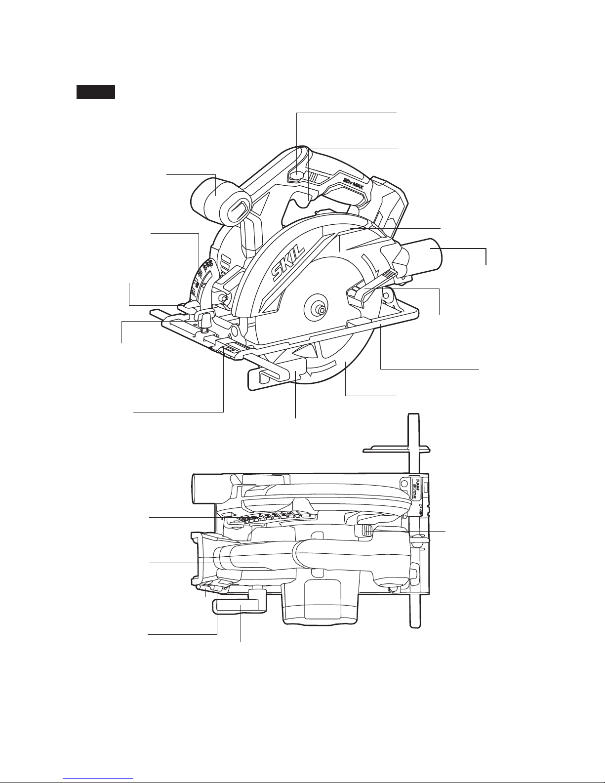
GET TO KNOW YOUR CIRCULAR SAW
20V 6-1/2’’ Circular Saw
Auxiliary Handle
Rip-Fence Locking
Knob
Bevel-Adjustment
Knob
Bevel Gauge
Saw-Line
Window
Depth-of-cut
Gauge
Main Handle
Hex key
Key Storage
Area
Extension
for Vacuum
Cleaner
Lock-off Button
Trigger Switch
Upper Guard
Lower-Guard Lift
Lever
SpindleLock Button
Depth-of-cut
Adjustment Lever
Foot
Lower Guard
Rip Fence (included
with some models)
Fig. 1
Page 12

12
SPECIFICATIONS
Rated voltage 20V d.c.
No-load speed 4500 /min
Blade diameter 6-1/2’’ (165mm)
Blade arbor 5/8’’ (16mm)
Cutting depth at 90° 2-1/8’’ (54mm)
Cutting depth at 45° 1-3/4’’ (44.5mm)
Bevel range 0°~50°
Recommended working temperature 14 ~ 104°F (-10 ~ 40°C)
Recommended storage temperature 32 ~ 104°F (0 ~ 40°C)
Page 13
13
OPERATING INSTRUCTIONS
WARNING
To reduce the risk of re, personal injury, and product damage due to
a short circuit, never immerse your tool, battery pack or charger in
uid or allow a uid to ow inside them. Corrosive or conductive uids, such as seawater,
certain industrial chemicals, and bleach or bleach-containing products, etc., can cause a
short circuit.
WARNING
If any parts are damaged or missing, do not operate this product until
the parts are replaced. Use of this product with damaged or missing
parts could result in serious personal injury.
WARNING
Do not attempt to modify this tool or create accessories not
recommended for use with this tool. Any such alteration or modication
is misuse and could result in a hazardous condition leading to possible serious injury.
WARNING
To prevent accidental starting that could cause serious personal
injury, always remove the battery pack from the tool when assembling
parts.
This cordless circular saw must be used only with the battery packs and charger listed
below:
Battery Pack
Charger
2Ah 4Ah 5Ah
SKIL BY519701 SKIL BY519601 SKIL BY519603 SKIL SC535801
NOTICE: Please refer to the battery pack and charger manuals for detailed operating
information.
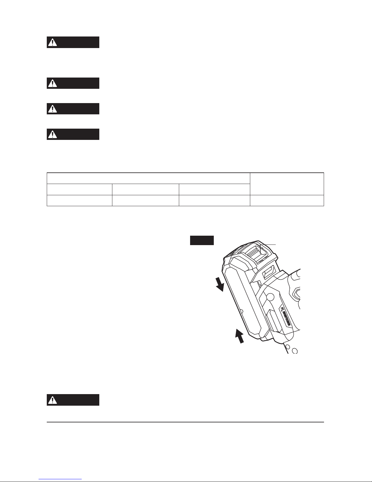
To Attach/Detach Battery Pack
(Fig. 2)
To attach the battery pack:
Align the raised rib on the battery pack with the
grooves of the tool, and then slide the battery
pack onto the tool.
NOTICE: Make sure that the latch on the
battery pack snaps into place and that the
battery pack is secured to the tool before
beginning operation.
To detach the battery pack:
Depress the battery-release button, located
on the front of the battery pack, to release the
battery pack. Pull the battery pack out and
remove it from the tool.
NOTICE: When placing the battery pack on the tool, be sure that the raised rib on the battery
pack aligns with the groove inside the tool and that the latches snap into place properly.
Improper attachment of the battery pack can cause damage to internal components.
WARNING
Battery tools are always in operating condition. Therefore, remove the
battery when the tool is not in use or when carrying it at your side.
Fig. 2
Attach
Detach
BatteryRelease Button
Page 14
14
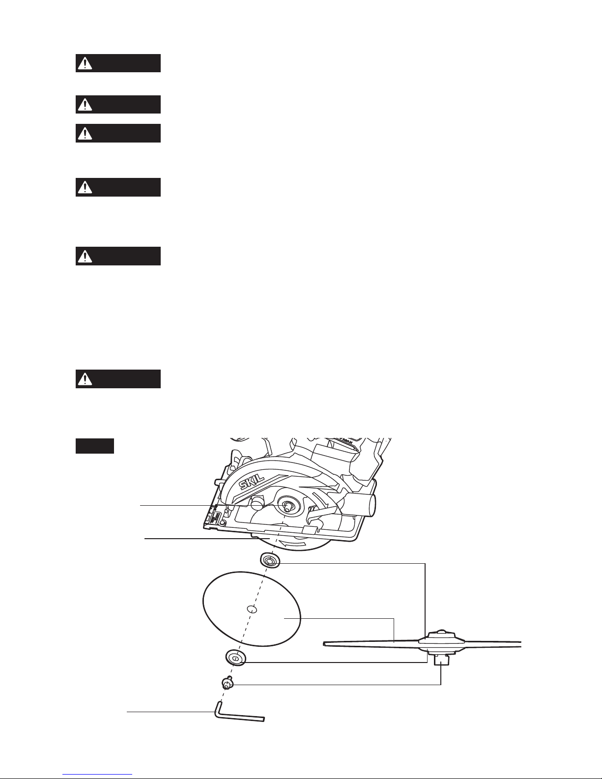
Attaching the Blade (Fig. 3)
WARNING
Detach the battery pack from the tool before performing any
assembly, adjustments, or changing accessories. Such preventive
safety measures reduce the risk of starting the tool accidentally.
WARNING
This tool is for cutting wood only. Use only the correct saw blades for
wood-cutting operations. Do not use any abrasive wheels.
WARNING
Use only 6-1/2’’ saw blade rated 4500/min (RPM) or greater. NEVER
use a blade that is so thick that it prevents the outer blade washer
from engaging with the at side of the spindle. Using a blade not designed for the saw
may result in serious personal injury and property damage.
WARNING
Be sure to wear protective work gloves while handling a saw blade.
The blade can injure unprotected hands.
a. Press the spindle-lock button and turn the hex key until the spindle-lock button engages.
The saw shaft is now locked. Continue to depress the spindle-lock button, turn the hex key
clockwise, and remove the blade bolt and the outer washer.
WARNING
Depress the spindle-lock button only when the tool is at a standstill.
b. Make sure that the saw teeth and the arrow on the blade point in the same direction as the
arrow on the lower guard.
c. Retract the lower guard all the way up into the upper guard. While retracting the lower
guard, check the operation and condition of the lower guard system.
d. Slide the blade through the slot in the foot and mount it against the inner washer on the
shaft. Be sure that the clamping surfaces of the inner and outer washers lay ush against
the blade.
WARNING
Make sure that the clamping surfaces of inner and outer washers are
perfectly clean and face the blade.
e. Reinstall the outer washer. First tighten the blade bolt nger tight, then tighten the blade bolt
1/8 turn (45°) with the hex key (this ensures slippage of the saw blade when it encounters
excessive resistance, thus reducing motor overload and saw kickback).
Fig. 3
Blade Shaft
Lower Guard
Hex key
Inner Washer
Blade
Outer Washer
Blade Bolt
Page 15
15
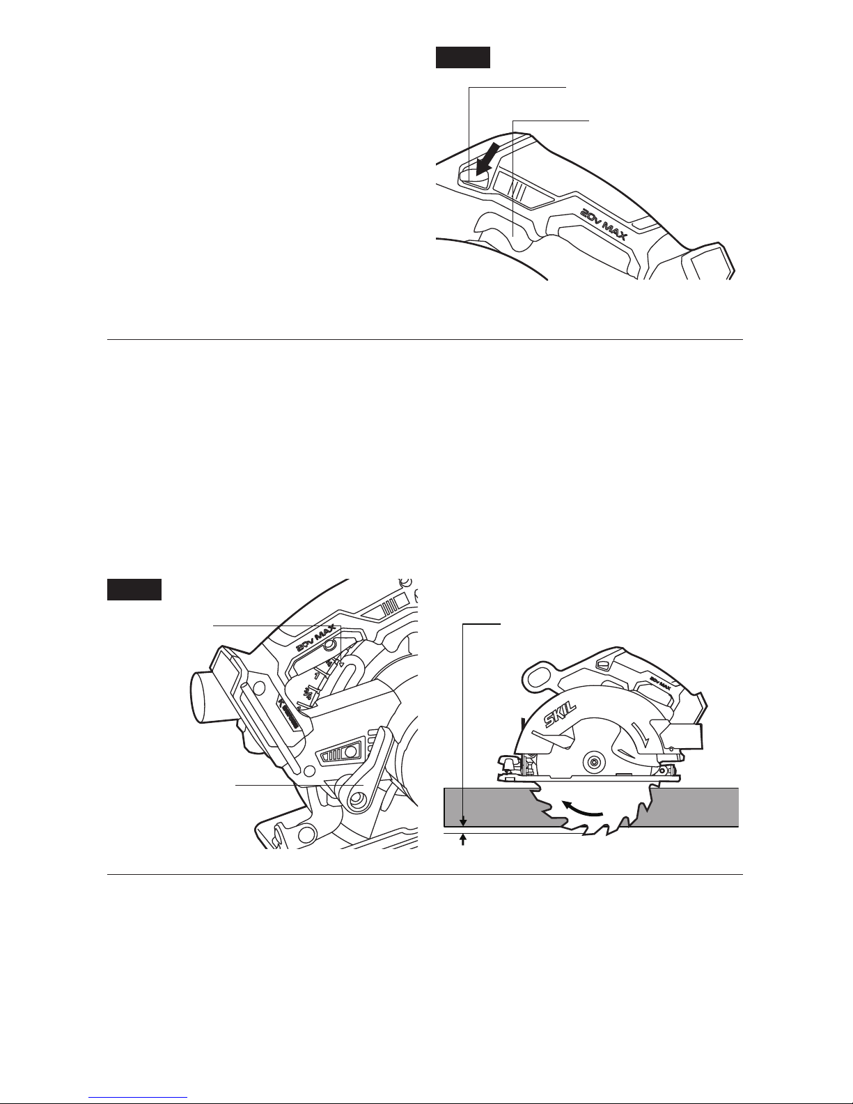
Lock-Off Button (Fig. 4)
The lock-off button is located on the handle
above the trigger switch. It reduces the
possibility of accidental starting for personal
safety protection.
The lock-off button must be pushed in before
pulling the trigger switch.
Depth-of-Cut Adjustment (Fig. 5)
The depth-of-cut adjustment lever is located beside the main handle.
a. Detach the battery pack from the tool.
b. Loosen the depth-of-cut adjustment lever.
c. Hold the foot of the saw at against the edge of the workpiece and then raise or lower the
saw until the indicator mark on the depth-of-cut gauge aligns with the desired depth-of-cut
mark.
d. Securely tighten the depth-of-cut adjustment lever at the desired depth-of-cut.
NOTICE: Check the depth-of-cut setting. Not more than one tooth length of the blade should
extend below the material to be cut, for minimum splintering.
Fig. 5
Indicator Mark
ONE TOOTH LENGTH
SHOULD PENETRATE WOOD
FOR MINIMUM SPLINTERING
Depth-of-cut
Adjustment Lever
Fig. 4
Lock-Off Button
Trigger Switch
Page 16

16
Bevel Adjustment (Fig. 6)
The bevel-adjustment knob adjusts the cutting
angle.
a. Detach the battery pack from the tool.
b. Loosen the bevel-adjustment knob by
rotating the knob counterclockwise.
c. Tilt the foot until the bevel-indicator mark
reaches the desired setting on the bevel
gauge.
d. Securely tighten the bevel-adjustment knob
by rotating the knob clockwise.
WARNING
Attempting to make bevel
cuts without the bevel-
adjustment knob securely tightened can
result in serious injury.
WARNING
Because of the increased amount of blade engagement in the work
while bevel cutting and decreased stability of the foot, blade binding
may occur. Keep the saw steady and the foot rmly on the workpiece.
NOTICE: When bevel cutting, the depth of cut does not correspond with value on the depth
of cut gauge.
NOTICE: Since the blade thicknesses vary and different angles require different settings,
always make a trial cut in scrap material along a guideline to determine how much you should
offset the guideline on the workpiece to be cut.
0° Bevel Check and Adjustment (Fig. 7)
Your tool has a 0° bevel stop, which has been adjusted before shipment to assure that the
blade is vertical to the foot at 0°bevel cutting.
To check and adjust to 0° Bevel:
a. Detach the battery pack from the tool.
b. Set the foot to the maximum depth-of-cut setting. Loosen the bevel-adjustment knob, set
the saw to 0° bevel on the bevel gauge, retighten the bevel-adjustment knob.
c. Turn the saw upside down and place it on a stable surface. Check for an angle of 90°
between the blade and the underside of the foot with a square.
d. If adjustment is necessary, loosen the bevel-adjustment knob. Place the saw in an upside-
down position on a workbench. Use a Philips-screwdriver to turn the 0° bevel-stopadjustment screw until the foot is square with the saw blade.
Fig. 7
Carpenter’s
Square
Blade
Foot
Bevel-StopAdjustment Screw
Fig. 6
Indicator Mark
BevelAdjustment
Knob
Page 17
17
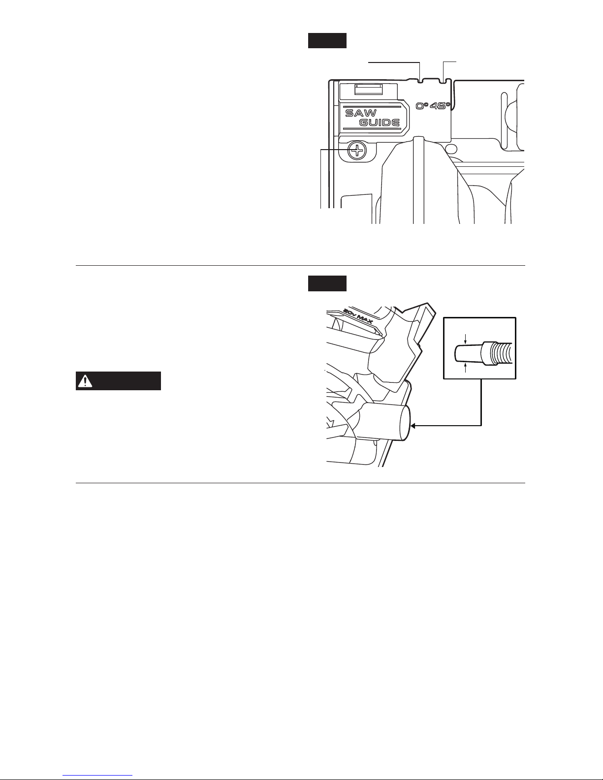
Saw-Line Window (Fig. 8)
For a 0° cut, align your line of cut with the left
notch in the foot at the 0° indicator.
For 45° bevel cuts, align your line of cut with
the right notch at the 45° indicator.
The saw-line window is also adjustable by
loosening the screw and realigning the window,
according to your need.
The saw-line window will give an approximate
line of cut. Make sample cuts in scrap lumber
to verify the actual line of cut. This will be
helpful because of the number of different
blade types and thicknesses available. To
ensure minimum splintering on the good side
of the material to be cut, face the good side
down.
Extension for Vacuum Cleaner
(Fig. 9)
Your tool is equipped with an extension (Ø11/4’’) for connecting a vacuum cleaner.
Choose a suitable vacuum-cleaner hose or use
an adapter, if necessary.
WARNING
Never allow a vacuumcleaner hose interfere
with the lower guard or cutting operation.
Fig. 9
Fig. 8
0° Indicator
Screw
45° Indicator
Page 18
18
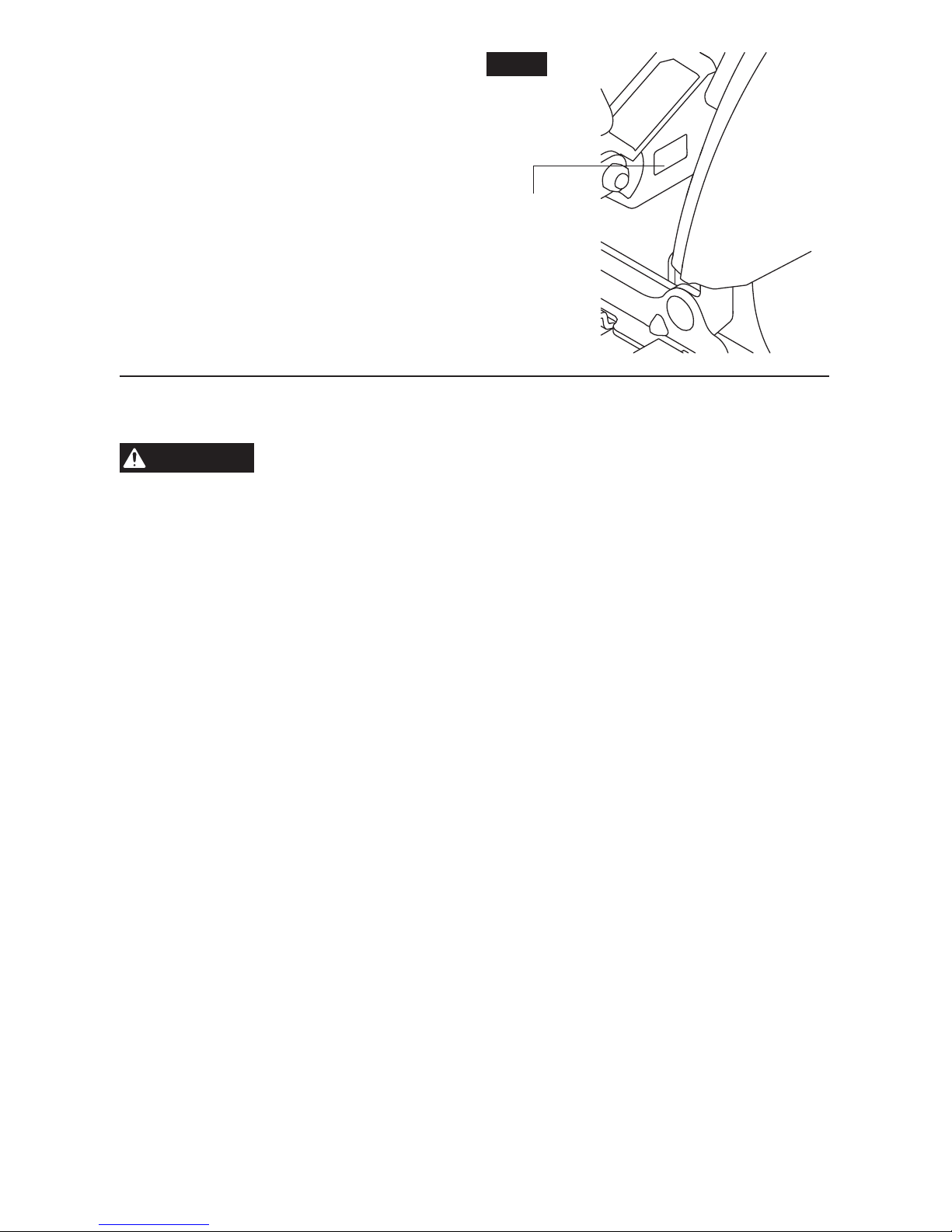
LED Light (Fig. 10)
An LED light is located behind the upper guard.
This provides additional light on the saw blade
and the surface of the workpiece for operation
in lower-light areas.
The LED light will automatically turn on when
the trigger switch is pressed and will turn off
after the trigger switch is released.
If the tool and/or battery pack becomes
overloaded or too hot, the internal sensors will
turn the tool off, and the LED light will rapidly
ash. Rest the tool for a while or place the tool
and battery pack separately under air ow for
cooling.
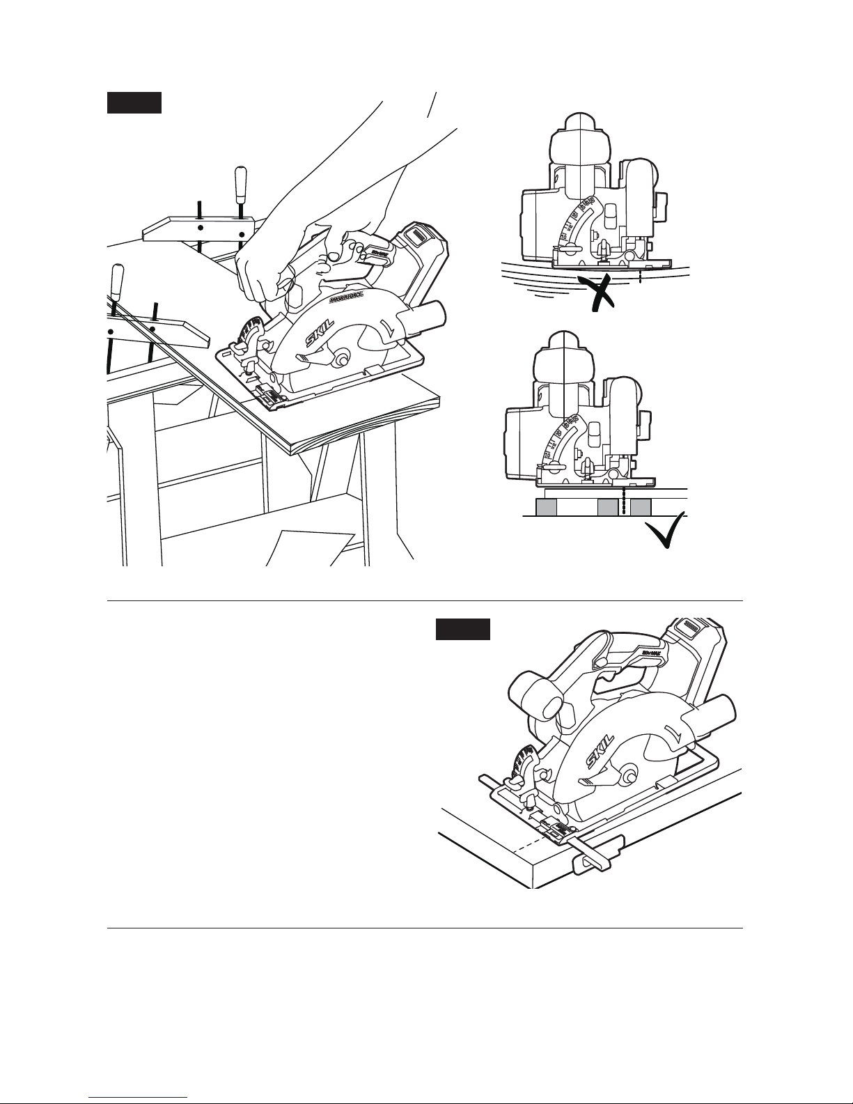
Cutting with the Circular Saw (Fig. 11)
Refer to the gures in this section to learn the correct and incorrect ways of handling the saw.
WARNING
•
To make sawing easier and safer, always maintain proper control of the saw. Loss of
control could cause an accident resulting in serious injury.
•
Maintain a rm grip and operate the trigger switch with a decisive action. Never force
the saw. Use light and continuous pressure.
•
When lifting the saw from the workpiece, the blade is exposed on the underside of the
saw until the lower blade guard closes. Make sure that the lower blade guard is closed
before setting the saw down.
To make the safest and best possible cut, follow these helpful hints:
a. Hold the saw rmly with both hands.
b. Avoid placing your hand on the workpiece while making a cut.
c. Support the workpiece so that the cut is always to the operator’s side and not directly in
line with the operator’s body.
d. Support the workpiece near the cut.
e. Clamp the workpiece securely so that the workpiece will not move during the cut.
f. Always place the saw on the portion of the workpiece that is supported, and not on the “cut
off” piece.
g. Place the workpiece with the “good” side down.
h. Draw a guideline along the desired cutting line before beginning the cut.
i. Rest the front edge of the foot on the workpiece without touching the blade to the
workpiece
j. Depress the trigger switch to start the saw.
k. Allow the blade to reach full speed, then guide the saw into the workpiece and make the
cut.
l. Release the trigger switch and allow the blade to come to a complete stop.
m.
Lift the saw from the workpiece.
NOTICE: Do not bind the blade in the cut.
When cutting is interrupted, to resume cutting: squeeze the trigger and allow the blade to
reach full speed, re-enter the cut slowly, and resume cutting.
Fig. 10
LED Light
Page 19
19
When cutting across the grain, the bers of the wood have a tendency to tear and lift.
Advancing the saw slowly will minimize this effect.
Fig. 11
Cross-Cutting/Rip Cutting
(Fig. 12)
When making a cross-cut or a rip cut, align
the guideline with the 0˚ indicator notch on the
foot. The distance from the saw blade to the
saw base is approximately 1-3/8 in. (35mm) on
the left side of the saw and 4-1/6 in. (105mm)
on the right.
Blade thicknesses vary, so you should always
make a trial cut in scrap material along a
guideline to determine how much the guideline
must be offset from the guide to produce an
accurate cut.
NOTICE: Use a guide when making long or
wide rip cuts.
Fig. 12
Page 20
20
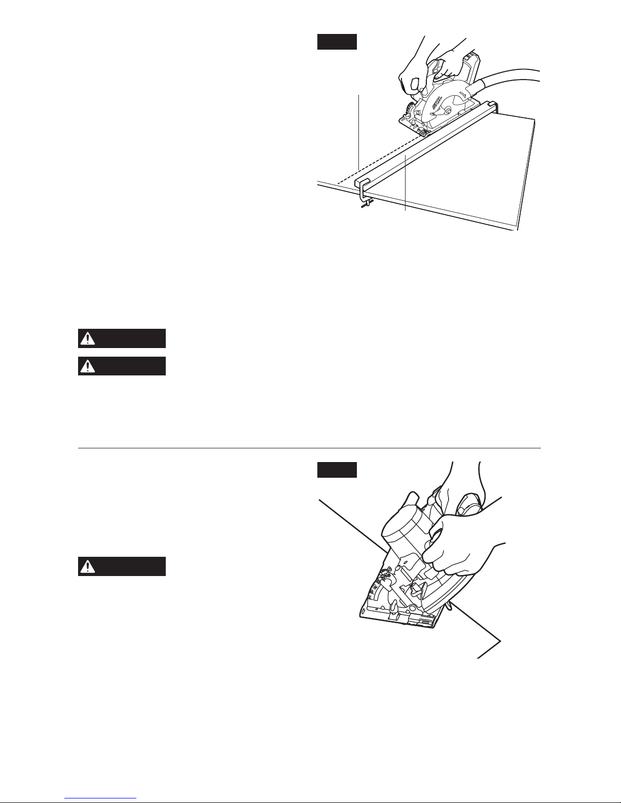
Rip Cutting Using a Straight Edge
(Fig. 13)
a. Secure the workpiece.
b. Clamp a straight edge to the workpiece
using C-clamps (not included).
NOTICE: Position the C-clamps so that they
will not interfere with the saw housing during
the cut.
c. Rest the front edge of the foot on the
workpiece without touching the blade to the
workpiece.
d. Depress the trigger switch to start the saw.
e. Allow the blade to reach full speed, then
guide the saw into the workpiece and make
the cut.
f. Saw along the straight edge to achieve a straight rip cut.
g. Release the trigger switch and allow the blade to come to a complete stop.
h. Lift the saw from the workpiece.
NOTICE: Do not bind the blade in the cut.
CAUTION
Always be sure that neither hand interferes with the free movement of
the lower guard.
CAUTION
After completing a cut and releasing the trigger, be aware of the
necessary time it takes for the blade to come to a complete stop
during coast down. Do not allow the saw to brush against your leg or side. Since the
lower guard is retractable, it could catch on your clothing and expose the blade. Be
aware of the necessary blade exposures that exist in both the upper and lower guard
areas.
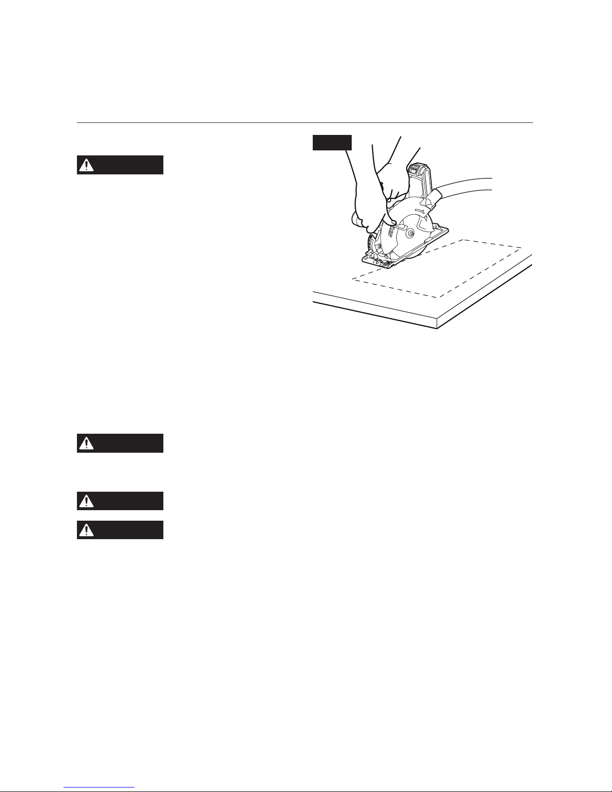
Bevel Cutting (Fig. 14)
To make the best possible cut:
a. Remove the battery from the saw.
b. Adjust the angle of cut to any desired setting
between 0° and 50°. Securely tighten the
bevel-adjustment knob.
WARNING
Attempting a bevel cut
without having the bevel-
adjustment knob securely locked in place
can result in serious injury.
c. Attach the battery pack
d. Align the cutting line with the 45° indicator
notch on the foot when making 45° bevel
cuts.
e. Make a trial cut in scrap material along a guideline to determine the amount to offset the
guideline on the cutting material.
f. Hold the saw rmly with both hands, as shown.
g. Rest the front edge of the foot on the workpiece without touching the blade to the
workpiece.
h. Depress the trigger switch to start the saw.
Fig. 14
Fig. 13
Desired Line
of Cut
Straight Edge
Page 21
21
i. Allow the blade to reach full speed, then guide the saw into the workpiece and make the
cut.
j. Release the trigger switch and allow the blade to come to a complete stop.
k. Lift the saw from the workpiece.
NOTICE: Do not bind the blade in the cut.
Plunge Cuts (Fig. 15)
WARNING
Always adjust the bevel
setting to zero before
making a plunge cut. Attempting a plunge
cut at any other setting can result in a loss
of control of the saw, which can result in
serious injury.
a. Detach the battery pack from the tool before
making any adjustment.
b. Adjust the depth of cut according to the
thickness of the material to be cut.
c. Attach the battery pack.
d. Holding the main handle of the saw with one
hand, tilt saw forward and rest front of the
foot plate on material to be cut. Line up the
saw line indicator with the line you’ve drawn.
e. Raise the lower guard using lower guard lift lever and hold the front of the foot plate with
the other hand.
f. Position the saw with the blade just clearing the material to be cut. Start the motor and
once fully up to speed, gradually lower the back end of saw, using the front end of the foot
as a hinge point.
WARNING
Once the foot plate rests at on the surface being cut, release the
lower guard and move the hand holding the front of the foot plate to
hold the auxiliary handle.
g. Proceed cutting in forward direction to end of cut.
WARNING
Allow blade to come to a complete stop before lifting the saw from
cut.
WARNING
Never pull the saw backward, since blade will climb out of the
material and KICKBACK will occur.
h. Turn the saw around and nish the cut in the normal manner, sawing forward.
i. If corners of your plunge cut are not completely cut through, use a jigsaw or hand saw to
nish the corners.
Fig. 15
Page 22

22
MAINTENANCE
WARNING
To avoid serious personal injury, always remove the battery pack from
the tool when cleaning or performing any maintenance.
Service
WARNING
Preventive maintenance performed by unauthorized personnel may
result in misplacing internal wires and components, which could
cause serious hazard. We recommend that all tool service be performed by a SKIL Factory
Service Center or Authorized SKIL Service Station.
General Maintenance
WARNING
When servicing, use only identical replacement parts. Use of any
other parts could create a hazard or cause product damage.
Periodically inspect the entire product for damaged, missing, or loose parts such as screws,
nuts, bolts, caps, etc. Tighten securely all fasteners and caps and do not operate this product
until all missing or damaged parts are replaced. Please contact customer service or an
authorized service center for assistance.
Cleaning
WARNING
The tool may be cleaned most effectively with compressed dry air. Always
wear safety goggles when cleaning tools with compressed air.
Ventilation openings and switch selectors must be kept clean and free of foreign matter. Do
not attempt to clean by inserting pointed objects through openings.
WARNING
Certain cleaning agents and solvents damage plastic parts. Some of
these are: gasoline, carbon tetrachloride, chlorinated cleaning solvents,
ammonia and house hold detergents that contain ammonia.
Storage
Store the tool indoors in a place that is inaccessible to children. Keep away from corrosive
agents.
Care of Blades
Blades become dull even from cutting regular lumber. If you nd yourself forcing the saw
forward to cut instead of just guiding it through the cut, chances are the blade is dull or
coated with wood pitch.
When cleaning gum and wood pitch from blade, detach the battery pack and remove the
blade.
Remember, blades are designed to cut, so handle them carefully. Wipe the blade with
kerosene or similar solvent to remove the gum and pitch.
Unless you are experienced in sharpening blades, we recommend that you do not try.
Replace the dull blade.
Page 23

23
TROUBLESHOOTING
Problem Cause Remedy
Tool does not start. 1. Battery pack is depleted.
2. Battery pack is not installed
properly.
3. Burned out switch.
1. Charge the battery.
2. Conrm battery is properly secured
to the tool.
3. Have the switch replaced by an
Authorized SKIL Service Center or
Service Station.
Blade does not
come up to speed.
1. Low battery. 1. Recharge the battery pack or use a
fully charged pack.
Excessive vibration. 1. Blade out of balance.
2. Workpiece not clamped or
supported properly.
1. Discard blade and use a different
blade.
2. Clamp or support workpiece
properly according to this manual.
The blade does not
follow a straight line.
1. Blade teeth are dull.
2. Foot is out of line or bent.
3. Blade is bent.
1. Change to a new blade.
2. Have the tool repaired by an
Authorized SKIL Service Center or
Service Station.
3. Change to a new blade.
Cut binds, burns,
stalls motor when
ripping.
1. Dull blade with improper
tooth set.
2. Blade binds.
3. Improper workpiece
support.
1. Discard blade and use a different
blade.
2. Reassemble the blade and tighten
the washers according to this
manual.
3. Clamp or support workpiece
properly according to this manual.
Blade slipping. 1. Tool does not cut
workpiece.
1. Reassemble the blade and tighten
the washers according to this
manual.
Page 24

24
LIMITED WARRANTY OF SKIL CONSUMER TOOLS
5 YEAR LIMITED WARRANTY- LEGAL
Chervon North America, Inc. ("Seller") warrants to the original purchaser only, that all SKIL
consumer TOOLS will be free from defects in material or workmanship for a period of ve
years from date of purchase, if original purchaser registers the product within 30 days from
purchase. BATTERIES AND CHARGERS are warranted for 2 years. Product registration can
be completed online at www.Registermyskil.com. Original purchasers should also retain
their receipt as proof of purchase. THE FIVE-YEAR WARRANTY PERIOD FOR TOOLS IS
CONDITIONED ON REGISTRATION OF THE PRODUCT WITHIN 30 DAYS OF PURCHASE.
If original purchasers do not register their product timely, the foregoing limited warranty will
apply for a duration of three years for tools. All batteries and chargers will remain under the
two-year limited warranty.
Notwithstanding the foregoing, if a SKIL consumer tool is used for industrial, professional
or commercial purposes, the foregoing warranty will apply for a duration of ninety days,
regardless of registration.
SELLER’S SOLE OBLIGATION AND YOUR EXCLUSIVE REMEDY under this Limited Warranty
and, to the extent permitted by law, any warranty or condition implied by law, shall be the
repair or replacement of parts, without charge, which are defective in material or workmanship
and which have not been misused, carelessly handled, or repaired by persons other than
Seller or Authorized Service Station. To make a claim under this Limited Warranty, you must
return the complete product, transportation prepaid, to any SKIL Factory Service Center or
Authorized Service Station. For Authorized SKIL Power Tool Service Stations, please visit
www.Registermyskil.com or call 1-877-SKIL-999 (1-877-754-5999).
THIS LIMITED WARRANTY DOES NOT APPLY TO ACCESSORY ITEMS SUCH AS CIRCULAR
SAW BLADES, DRILL BITS, ROUTER BITS, JIGSAW BLADES, SANDING BELTS, GRINDING
WHEELS AND OTHER RELATED ITEMS.
ANY IMPLIED WARRANTIES APPLICABLE TO A PRODUCT SHALL BE LIMITED IN
DURATION EQUAL TO THE DURATION OF THE EXPRESS WARRANTIES APPLICABLE TO
SUCH PRODUCT, AS SET FORTH IN THE FIRST PARAGRAPH ABOVE. SOME STATES IN
THE U.S., SOME CANADIAN PROVINCES DO NOT ALLOW LIMITATIONS ON HOW LONG
AN IMPLIED WARRANTY LASTS, SO THE ABOVE LIMITATION MAY NOT APPLY TO YOU.
IN NO EVENT SHALL SELLER BE LIABLE FOR ANY INCIDENTAL OR CONSEQUENTIAL
DAMAGES (INCLUDING BUT NOT LIMITED TO LIABILITY FOR LOSS OF PROFITS) ARISING
FROM THE SALE OR USE OF THIS PRODUCT. SOME STATES IN THE U.S. AND SOME
CANADIAN PROVINCES DO NOT ALLOW THE EXCLUSION OR LIMITATION OF INCIDENTAL
OR CONSEQUENTIAL DAMAGES, SO THE ABOVE LIMITATION OR EXCLUSION MAY NOT
APPLY TO YOU.
THIS LIMITED WARRANTY GIVES YOU SPECIFIC LEGAL RIGHTS, AND YOU MAY ALSO
HAVE OTHER RIGHTS WHICH VARY FROM STATE TO STATE IN THE U.S., PROVINCE TO
PROVINCE IN CANADA AND FROM COUNTRY TO COUNTRY.
THIS LIMITED WARRANTY APPLIES ONLY TO PRODUCTS SOLD WITHIN THE UNITED
STATES OF AMERICA, CANADA AND THE COMMONWEALTH OF PUERTO RICO. FOR
WARRANTY COVERAGE WITHIN OTHER COUNTRIES, CONTACT YOUR LOCAL SKIL
DEALER OR IMPORTER.
© Chervon North America, 1203 E. Warrenville Rd, Naperville, IL 60563.
10/18
Page 25

25
TABLE DES MATIÈRES
Avertissements de sécurité généraux relatifs
aux outils électriques ........................................26-28
Avertissements relatifs à la sécurité pour les scies circulaires ......28-30
Symboles ..................................................31-34
Familiarisez-vous avec votre scie circulaire. . . . . . . . . . . . . . . . . . . . . . . . .35
Caractéristiques techniques .....................................36
Mode d’emploi ..............................................37-47
Entretien ......................................................48
Dépannage ....................................................49
Garantie limitée de l’outil sans l SKIL ..........................50-51
AVERTISSEMENT
•
La poussière créée pendant le ponçage, le sciage, le polissage, le perçage et d’autres activités liées à la construction peut contenir des produits chimiques reconnus par l’État de la
Californie comme étant la cause de cancers, d’anomalies congénitales et d’autres problèmes
liés aux fonctions reproductrices. Voici des exemples de ces produits chimiques :
–
Plomb provenant de peintures à base de plomb.
–
Silice cristallisée contenue dans les briques, le ciment et d’autres produits de maçonnerie.
–
Arsenic et chrome contenus dans le bois d’œuvre traité avec des produits chimiques.
•
Les risques liés à l’exposition à ces produits va-rient selon le nombre de fois où vous
pratiquez ces activités. Pour réduire votre exposition à ces produits chimiques :
–
travaillez dans un endroit bien ventilé;
–
munissez-vous de l’équipement de sécurité ap-prouvé tel que des masques antipoussières
conçus spécialement pour ltrer les particules microscopiques;
–
évitez l’exposition prolongée à la poussière causée par le ponçage mécanique, le sciage,
le polissage, le perçage et d’autres activités liées à la construction. Portez un équipement
de pro-tection et lavez à l’eau et au savon toutes les parties exposées. Les poussières
pénétrant dans votre bouche ou dans vos yeux et les poussières se déposant sur votre
peau peuvent causer l’absorption de produits chimiques dangereux.
Page 26

26
AVERTISSEMENTS DE SÉCURITÉ GÉNÉRAUX RELATIFS AUX
OUTILS ÉLECTRIQUES
AVERTISSEMENT
Lisez tous les avertissements et toutes les ins-tructions,
illustrations et spécications fournis avec cet outil
électrique. Le non-respect des consignes de sécurité ci-dessous peut occasionner un
choc électrique, un in-cendie ou des blessures graves.
CONSERVEZ TOUS LES AVERTISSEMENTS ET TOUTES
LES INSTRUCTIONS AFIN DE POUVOIR LES CON-SULTER
ULTÉRIEUREMENT.
L’expression « outil électrique » utilisée dans les avertissements correspond aux outils
électriques alimentés sur secteur (à l) ou alimentés par piles (sans l).
Mesures de sécurité dans l’aire de travail
Maintenez l’aire de travail propre et bien éclairée. Les aires de travail sombres et encombrées sont propices aux accidents.
N’utilisez pas d’outils électriques dans un en-droit présentant un risque d’explosion,
par exemple en présence de liquides, de gaz ou de poussières inam-mables. Les outils
électriques produisent des étincelles pouvant causer un incendie en raison de la poussière et
des fumées.
Gardez les enfants et les autres personnes à l’écart lorsque vous utilisez un outil
électrique. Une distraction peut vous faire perdre la maîtrise de l’outil.
Consignes de sécurité relatives à l’électricité
Les ches des outils électriques doivent cor-respondre à la prise. Ne modiez jamais
la che de quelque façon que ce soit. N’utilisez pas d’adaptateur avec les outils
électriques mis à la terre. L’utilisation de ches non modiées dans les prises compatibles
réduit les risques de choc électrique.
Évitez de toucher à des surfaces mises à la terre, par exemple, un tuyau, un radiateur,
une cuisi-nière ou un réfrigérateur. Le contact du corps avec une surface mise à la terre
augmente les risques de choc électrique.
N’exposez pas les outils électriques à la pluie ni à tout environnement humide. L’inltration
d’eau dans un outil électrique augmente les risques de choc électrique.
N’utilisez pas le cordon d’alimentation de façon à l’endommager. Ne transportez jamais
un outil électrique en le tenant par son cordon, et ne tirez jamais sur le cordon pour le
débrancher. Tenez le cordon d’alimentation éloigné des sources de chaleur, de l’huile,
des objets cou-pants et des pièces mobiles. Les risques de choc électrique sont plus
élevés si le cordon d’alimentation est endommagé ou emmêlé.
Lorsque vous utilisez un outil électrique à l’extérieur, utilisez une rallonge conçue pour
être utilisée à l’extérieur. Ce type de rallonge réduit les risques de choc électrique.
Si vous n’avez d’autre choix que d’utiliser un outil électrique dans un endroit humide,
utilisez une alimentation protégée par un disjoncteur différentiel. L’utilisation d’un
disjoncteur dif-férentiel réduit les risques de choc électrique.
Sécurité personnelle
Soyez vigilant, prêtez attention à ce que vous faites et usez de votre jugement lorsque
vous utilisez un outil électrique. N’utilisez pas un outil électrique lorsque vous êtes
fatigué ou sous l’effet de drogues, d’alcool ou de médicaments. Un moment d’inattention
lorsque vous utilisez des outils électriques peut occasionner des blessures graves.
Page 27

27
Utilisez un équipement individuel de protec-tion. Portez toujours des lunettes de sécurité.
Le port d’équipement de protection, comme un masque antipoussières, des chaussures de
sécu-rité antidérapantes, un casque de protection et des protecteurs auditifs, lorsque les
conditions l’exigent, réduit les risques de blessures.
Prenez des mesures an d’éviter que l’outil se mette en marche accidentellement.
Assu-rez-vous que l’interrupteur est à la position d’arrêt avant de brancher l’outil sur
une source d’alimentation ou un bloc-piles, de ramasser l’outil ou de le transporter.
Transporter les outils électriques avec le doigt sur la gâchette ou brancher les outils lorsque
l’interrupteur est à la position de marche augmente les risques d’accident.
Retirez toutes les clés de réglage de l’outil électrique avant de mettre celui-ci en
marche. Une clé de réglage oubliée sur une pièce rotative de l’outil électrique peut
occasionner des blessures graves.
Ne vous étirez pas pour étendre votre portée. Gardez une posture sécuritaire et un bon
équi-libre en tout temps. Cela vous permet de mieux maîtriser l’outil électrique lorsque des
situations inattendues se présentent.
Habillez-vous convenablement. Ne portez pas de vêtements amples ni de bijoux. Gardez
vos cheveux, vos vêtements et vos gants loin des pièces mobiles. Les vêtements amples,
les bijoux et les cheveux longs risquent de se prendre dans les pièces en mouvement.
Si un dispositif permet de raccorder un dé-poussiéreur, assurez-vous que celui-ci
est branché et utilisé correctement. L’emploi d’un dépoussiéreur contribue à réduire les
dangers liés à la pous-sière.
Restez toujours sur vos gardes et suivez les principes de sécurité des outils, même s’il
s’agit d’un outil que vous utilisez fréquemment. Il suft d’être négligent une fraction de
seconde pour se blesser gravement.
Utilisation et entretien d’un outil électrique
Ne forcez pas l’outil électrique. Utilisez l’outil électrique approprié à la tâche que vous
sou-haitez accomplir. L’utilisation de l’outil élec-trique approprié permet d’obtenir de
meilleurs résultats, de façon plus sécuritaire, selon le ré-gime de fonctionnement prévu.
N’utilisez pas l’outil électrique si l’interrupteur ne fonctionne pas. Tout outil électrique qui
ne peut être commandé au moyen de l’interrupteur est dangereux et doit être réparé.
Débranchez la che de la prise ou retirez, si possible, le bloc-piles de l’outil électrique
avant d’effectuer des réglages, de changer d’accessoire ou de le ranger. Ces mesures
de sécurité pré-ventives réduisent les risques de mise en marche accidentelle de l’outil
électrique.
Rangez les outils électriques inutilisés hors de la portée des enfants et ne laissez pas
les personnes ne connaissant pas bien l’outil ou ces instruc-tions utiliser l’outil. Les
outils électriques sont dangereux s’ils se retrouvent entre les mains d’utilisateurs qui ne
savent pas s’en servir.
Entretenez vos outils électriques et vos acces-soires. Vériez les pièces mobiles pour
vous assurer qu’elles ne sont pas désalignées, en-rayées, brisées, ou dans un état
qui pourrait nuire à leur fonctionnement. Si l’outil électrique est endommagé, faites-le
réparer avant de l’utiliser. De nombreux accidents sont provo-qués par des outils électriques
mal entretenus.
Gardez vos outils tranchants affûtés et propres. Des outils tranchants bien entretenus dont
les lames sont affûtées risquent moins de se bloquer et sont plus faciles à maîtriser.
Utilisez l’outil électrique, les accessoires, les embouts et les autres éléments
conformément aux présentes instructions, en tenant compte des conditions de travail
et du travail à effectuer. L’utilisation de l’outil électrique à des ns autres que celles pour
lesquelles il a été conçu pourrait créer une situation dangereuse.
Page 28

28
Gardez les poignées et les prises sèches, propres et exemptes d’huile et de graisse. Les
poignées et autres surfaces de préhension glissantes ne permettent pas de manipuler ni de
contrôler l’outil de façon sécuritaire en cas de situations inattendues.
Utilisation et entretien d’un outil alimenté par un bloc-piles
Rechargez uniquement le bloc-piles à l’aide du chargeur approuvé par le fabricant. Un
chargeur conçu pour un type de bloc-piles peut causer un incendie s’il est utilisé avec un
autre bloc-piles.
Utilisez les outils électriques uniquement avec les blocs-piles qui leur sont destinés.
L’utilisation de tout autre bloc-piles peut constituer un risque de blessure et d’incendie.
Lorsque vous n’utilisez pas le bloc-piles, con-servez-le à l’écart d’autres objets
métalliques, comme des trombones, des pièces de monnaie, des clés, des clous, des
vis et d’autres petits objets métalliques qui peuvent connecter une borne à une autre.
Un court-circuit entre les bornes du bloc-piles peut occasionner des brû-lures et un incendie.
En cas d’usage abusif, du liquide peut s’échapper des piles; évitez tout contact avec
celui-ci. En cas de contact accidentel, rincez à grande eau. En cas de contact avec les
yeux, consultez un mé-decin. Le liquide provenant des piles peut causer de l’irritation ou des
brûlures.
N’utilisez pas un bloc-piles ou un outil endommagé ou modié. Les blocs-piles modiés
ou endommagés peuvent fonctionner de façon imprévisible et représenter un risque
d’incendie, d’explosion ou de blessures.
N’exposez pas un bloc-piles ou un outil à un feu ou à une température excessive.
L’exposition au feu ou à une température supérieure à 129,4 °C peut provoquer une explosion.
Suivez toutes les instructions pour le charge-ment et ne chargez pas le bloc-piles ou
l’appareil en dehors de la plage de température spéciée dans les instructions. Une
recharge inadéquate ou effectuée à des températures en dehors de la plage spéciée peut
endommager le bloc-piles et augmenter le risque d’incendie.
Entretien
Demandez à un technicien qualié qui utilise seulement des pièces de rechange
identiques aux pièces d’origine d’effectuer l’entretien de votre outil électrique. Vous vous
assurerez ainsi de respecter les consignes de sécurité de l’outil électrique.
Ne réparez jamais un bloc-piles endommagé. Seuls le fabricant et les fournisseurs de
services autorisés peuvent effectuer la réparation d’un bloc-piles.
CONSIGNES DE SÉCURITÉ SUPPLÉMENTAIRES POUR LES
SCIES CIRCULAIRES
Procédures de coupe
DANGER
Gardez les mains à une distance sufsante de la zone de coupe et de la
lame. Maintenez votre autre main sur la poignée auxiliaire ou sur le
boîtier du moteur. Si vos deux mains tiennent la scie, elles ne peuvent pas être coupées par
la lame.
Ne tendez jamais le bras en dessous de l’ouvrage. Le dispositif de protection ne peut pas
vous protéger contre la lame en dessous de l’ouvrage.
Réglez la profondeur de coupe en fonction de l’épaisseur de l’ouvrage. Moins d'une dent
pleine de la lame doit être visible en dessous de l’ouvrage.
Ne tenez jamais l’ouvrage dans vos mains ou sur vos jambes pendant la coupe.
Sécurisez l’ouvrage sur une plateforme stable. Il est important de soutenir l’ouvrage
correctement pour minimiser l'exposition du corps, le coincement de la lame ou la perte de
contrôle.
Page 29

29
Tenez l’outil électrique par ses surfaces de préhension isolées lorsque vous effectuez
une opération dans le cadre de laquelle l’outil de coupe risque d’entrer en contact avec
un l caché. L’entrée en contact d’un outil de coupe avec un l sous tension pourrait rendre
conductrices des parties en métal exposées de l’outil électrique et causer un choc électrique
à l’opérateur.
Lors d’une coupe en long, utilisez toujours un guide de refente ou un guide droit. Ceci
améliore la précision de la coupe et réduit le risque de coincement de la lame.
Utilisez toujours des lames de scie avec des trous d’arbre de taille et de forme
appropriées (diamantés plutôt que ronds). Les lames de scie qui ne correspondent pas au
matériel de xation de la scie se décentreront et causeront une perte de contrôle.
N’utilisez jamais de rondelles de lame ou de boulon endommagés ou incorrects. Les
rondelles de lame et le boulon ont été spécialement conçus pour votre scie, pour assurer des
performances optimales et la sécurité du fonctionnement.
Causes des effets de rebond et avertissements associés
–
L'effet de rebond est une réaction soudaine à une lame de scie pincée, coincée ou mal
alignée, provoquant le soulèvement et le retrait d'une scie non contrôlés depuis l’ouvrage en
direction de l'opérateur ;
–
lorsque la lame est pincée ou coincée par la fermeture du trait de coupe, la lame se bloque
et la réaction du moteur dirige rapidement l'outil vers l'opérateur ;
–
Si la lame devient tordue ou mal alignée dans la coupe, les dents du bord arrière de la lame
peuvent pénétrer dans la surface supérieure du bois, ce qui a pour conséquence que la
lame sort du trait de coupe et se dirige vers l'opérateur.
Le rebond est la conséquence d’une utilisation incorrecte de la scie et/ou de conditions
inappropriées ou de procédures opérationnelles incorrectes ; il peut être évité en prenant des
précautions appropriées, comme cela est indiqué ci-dessous.
Maintenez une prise ferme avec les deux mains sur la scie, et positionnez vos bras
pour résister aux forces de l’effet de rebond. Placez votre corps de l’un quelconque des
côtés de la lame, mais pas de manière qu’il soit aligné sur la trajectoire de la lame. L’effet
de rebond pourrait faire reculer très vite la scie, mais l'opérateur peut contrôler les forces de
l’effet de rebond si les précautions nécessaires sont prises.
Lorsque la lame se coince ou lorsque vous interrompez une coupe pour une raison
quelconque, relâchez la gâchette et maintenez la scie immobile dans le matériau
jusqu'à ce que la lame se soit complètement arrêtée. N'essayez jamais de retirer la scie
de l’ouvrage ou de tirer la scie vers l'arrière lorsque la lame est en mouvement, sans
quoi un effet de rebond pourrait se produire. Inspectez la scie et prenez les mesures qui
s'imposent pour éliminer la cause du blocage de la lame
Lorsque vous remettez une scie dont la lame est engagée dans un ouvrage en marche,
centrez la lame de la scie sur le trait de coupe de manière que les dents de la scie
ne soient pas engagées dans le matériau. Si une lame de scie se coince, elle risque de
remonter ou de rebondir hors de l’ouvrage lorsque la scie est remise en marche.
Soutenez les grands panneaux pour minimiser les risques de pincement de la lame de la
scie et de choc en retour. Les grands panneaux ont tendance à s’affaisser sous leur propre
poids. Les supports doivent être placés sous le panneau des deux côtés, près de la ligne de
coupe et près du bord du panneau.
N’utilisez jamais de lames émoussées ou endommagées. Les lames mal affûtées ou mal
réglées produisent un trait de coupe étroit provoquant un frottement excessif, le coincement
de la lame et un effet de rebond.
Les leviers de verrouillage de la profondeur de la lame et du réglage du biseau doivent
être serrés et sécurisés avant de procéder à la coupe. Si le réglage de la lame change
pendant la coupe, cela peut provoquer un coincement et un effet de rebond.
Page 30

30
Faites particulièrement attention lorsque vous sciez des murs existants ou d’autres
structures sans visibilité. La lame saillante risquerait de couper des objets pouvant causer
un effet de rebond.
Fonction du dispositif de protection inférieur
Inspectez le dispositif de protection inférieur de la lame pour vous assurer qu’il se
ferme complètement avant chaque utilisation. N’utilisez pas la scie si le dispositif
de protection inférieur de la lame ne se déplace pas librement et ne se ferme pas
instantanément. N’immobilisez jamais (que ce soit par une bride ou un l quelconque)
le dispositif de protection de la lame en position ouverte. Si vous avez laissé tomber la
scie accidentellement, il se peut que le dispositif de protection inférieur soit tordu. Soulevez
le dispositif de protection inférieur avec la poignée rétractable et assurez-vous qu'il bouge
librement et ne touche pas la lame ou toute autre pièce, à tous les angles et à toutes les
profondeurs de la coupe.
Vériez le fonctionnement du ressort du dispositif de protection inférieur. Si le dispositif
de protection et le ressort ne fonctionnent pas correctement, ils doivent être réparés
avant toute nouvelle utilisation. Le dispositif de protection inférieur risque de fonctionner
lentement à cause de pièces endommagées, de dépôts de gomme ou d'une accumulation de
débris.
Le dispositif de protection inférieur ne peut être rétracté manuellement que pour des
coupes spéciales telles que les « coupes plongeantes » et les « coupes composées ».
Soulevez le dispositif de protection inférieur par la poignée rétractable et, dès que la
lame pénètre dans le matériau, le dispositif de protection inférieur doit être relâché.
Pour toutes les autres opérations de sciage, le dispositif de protection inférieur doit pouvoir
fonctionner automatiquement.
Vériez toujours que le dispositif de protection inférieur couvre la lame avant de poser
la scie sur un banc ou sur le sol. Une lame sans protection et en roue libre fera reculer la
scie, coupant tout ce qui est sur son passage. Soyez au courant du temps qui est nécessaire
pour que la lame s'arrête après le relâchement de l'interrupteur.
Page 31

31
SYMBOLES
Symboles de sécurité
L’objectif des symboles de sécurité est d’attirer votre attention sur les dangers potentiels.
Vous devez examiner attentivement et bien com-prendre les symboles de sécurité et les explications qui les accompagnent. Les symboles d’avertissement en tant que tels n’éliminent pas
le danger. Les consignes et les avertissements qui y sont associés ne remplacent en aucun
cas des mesures préventives adéquates.
AVERTISSEMENT
Avant d’utiliser cet outil, assurez-vous de lire et de
comprendre toutes les consignes de sécurité présentées
dans le présent guide d’utilisation, notamment toutes les consignes de sécurité
indiquées par les mentions « DANGER », « AVERTISSEMENT » et « MISE EN GARDE ».
Le non-respect des consignes qui suivent peut entraîner un choc électrique, un
incendie ou des blessures graves.
Les dénitions ci-dessous décrivent le degré de gravité pour chaque mot-indicateur. Veuillez lire
ce manuel et prêter attention à ces symboles.
Voici le pictogramme d’alerte de sécurité. Il sert à vous
indiquer les risques potentiels de blessures. Respectez toutes
les consignes de sécurité associées à ce pictogramme pour
éviter les risques de blessures ou de mort.
DANGER
La mention DANGER indique un danger imminent qui, s’il n’est
pas évité, causera des blessures graves ou la mort.
AVERTISSEMENT
La mention AVERTISSEMENT indique un risque pouvant
entraîner des blessures graves ou la mort s’il n’est pas
prévenu.
ATTENTION
La mention ATTENTION, utilisée avec le symbole d’alerte de
sécurité, indique un risque potentiel qui, s’il n’est pas éliminé,
provoquera des blessures mineures ou moyennement graves.
Messages d’information et de prévention des dommages
Ces messages fournissent à l’utilisateur de l’information et des consignes importantes. Les
ignorer pourrait occasionner des dommages à l’équipement ou d’autres dommages matériels.
Chaque message est précédé du mot « AVIS », comme dans l’exemple ci-dessous :
AVIS : Ne pas suivre ces consignes pourrait occasionner des dommages à l’équipement
ou d’autres dommages matériels.
AVERTISSEMENT
L’utilisation de tout outil électrique peut
entraîner la projection de corps étrangers
dans les yeux et ainsi causer des lésions oculaires graves. Avant
d’utiliser un outil élec-trique, veillez à toujours porter des lunettes de
sécurité étanches ou à écrans latéraux, ou un masque de protection
complet au besoin. Nous recommandons le port d’un masque de
sécurité panoramique par-dessus les lunettes ou de lu-nettes de sécurité
standard avec écrans latéraux. Portez toujours des protecteurs oculaires
conformes à la norme ANSI Z87.1.
Page 32

32
SYMBOLES (SUITE)
IMPORTANT : Les symboles suivants peuvent gurer sur votre outil. Familiarisez-vous
avec eux et apprenez leur signication. En comprenant ces symboles, vous serez en
mesure de faire fonctionner cet outil de façon adéquate et sécuritaire.
Symbole Nom Forme au long et explication
V Volts Tension (possible)
A Ampères Courant
Hz Hertz Fréquence (cycles par seconde)
W Watt Puissance
kg Kilogrammes Poids
min Minutes Durée
s Secondes Durée
Wh Wattheures Capacité de la pile
Ah Ampères-heures Capacité de la pile
Ø Diamètre Taille des forets, des meules, etc.
n
0
Vitesse à vide Vitesse de rotation à vide
n Vitesse nominale Vitesse maximale atteignable
…/min
Tours ou va-et-vient par
minute
Tours, coups, vitesse périphérique,
orbites, etc., par minute
0 Position d’arrêt Vitesse nulle, couple nul...
1,2,3,…
I,II,III,
Réglages du sélecteur
Réglages de la vitesse, du couple ou de
la posi-tion. Plus le nombre est élevé,
plus la vitesse est grande.
Sélecteur à réglage continu
avec mode d’arrêt
La vitesse augmente à partir du réglage 0
Flèche
L’activation se fait dans le sens de la
èche
Courant alternatif
Type de courant ou caractéristique de
courant
Courant continu
Type de courant ou caractéristique de
courant
Courant alternatif ou continu
Type de courant ou caractéristique de
courant
Appareil de classe II
Désigne les outils de construction à
double isolation
Borne de mise à la terre Borne de mise à la terre
Page 33

33
Symbole Nom Forme au long et explication
Label du programme de
recyclage des piles au
lithium-ion de la RBRC
Désigne le programme de recyclage des
piles au lithium-ion
Label du programme de
recyclage des piles au
nickel-cadmium de la RBRC
Désigne le programme de recyclage des
piles au nickel-cadmium
Symbole de lecture du
manuel
Invite l’utilisateur à lire le manuel
Symbole du port de lunettes
de sécurité
Lorsque vous utilisez cet article, portez
toujours des lunettes de sécurité
étanches ou à écrans latéraux, ou un
masque de protection complet.
Page 34

34
SYMBOLES (RENSEIGNEMENTS EN MATIÈRE
D’HOMOLOGATION)
IMPORTANT :
Certains des symboles suivants, qui fournissent des renseignements
en matière d’homologation, peuvent gurer sur l’outil. Familiarisez-vous avec eux et
apprenez leur si-gnication. En comprenant ces symboles, vous serez en mesure de
faire fonctionner cet outil de façon adéquate et sécuritaire.
Symbole Forme au long et explication
Ce symbole indique que cet outil est répertorié par Underwriters
Laboratories.
Ce symbole indique que cet outil est reconnu par Underwriters
Laboratories.
Ce symbole indique que cet outil est répertorié par Underwriters
Laboratories et qu’il est conforme aux normes américaines et
canadiennes.
Ce symbole indique que cet outil est répertorié par l’Association
canadienne de normalisation.
Ce symbole indique que cet outil est répertorié par l’Association
canadienne de normalisation et qu’il est conforme aux normes
américaines et canadiennes.
Ce symbole indique que cet outil est répertorié par Intertek Testing et
qu’il est conforme aux normes américaines et canadiennes.
Ce symbole indique que cet outil est conforme aux normes mexicaines
ofcielles (NOM).
Page 35

35
FAMILIARISEZ-VOUS AVEC VOTRE SCIE CIRCULAIRE
Scie circulaire de 20 V 6-1/2 po
Poignée auxiliaire
Bouton de verrouillage
du guide de refente
Bouton de réglage
du biseau
Jauge de
biseau
Fenêtre de vision
du trait de coupe
Jauge de
profondeur
de coupe
Poignée principale
Clé hexagonale
Aire de
stockage de
clés
Rallonge
pour
aspirateur
Bouton de
déverrouillage
Interrupteur à gâchette
Dispositif de
protection
supérieur
Levier de
réglage du
dispositif de
protection
inférieur
Bouton de
verrouillage
de la broche
Levier de réglage de la
profondeur de coupe
Pied
Dispositif de protection inférieur
Guide de refente (inclus
avec certains modèles)
Fig. 1
Page 36

36
CARACTÉRISTIQUES TECHNIQUES
Tension nominale 20 V c.c.
Vitesse à vide 4 500 / min
Diamètre de la lame 165 mm (6-1/2 po)
Arbre de la lame 16 mm (5/8 po)
Profondeur de coupe à 90° 54 mm (2-1/8 po)
Profondeur de coupe à 45° 44,5 mm (1-3/4 po)
Plage de biseaux 0°~50°
Température de fonctionnement
recommandée
de -10 °C à environ 40 °C (de 14 °F à environ 104 °F)
Température de rangement
recommandée
de 0 °C à environ 40 °C (de 32 °F à environ 104 °F)
Page 37

37
MODE D’EMPLOI
AVERTISSEMENT
Pour réduire les risques d’incendie, de blessures
corporelles et de détérioration de l’outil découlant d’un
court-circuit, ne plongez jamais l’outil, le bloc-piles ou le chargeur dans un liquide et ne
laissez aucun liquide s’écouler sur ceux-ci. Les liquides corrosifs ou conducteurs, tels que
l’eau de mer, certains produits chimiques industriels, l’eau de javel, les produits contenant de
l’eau de Javel, etc., peuvent causer un court-circuit..
AVERTISSEMENT
S’il y a des pièces manquantes ou endommagées, ne tentez
pas d’utiliser l’article tant que ces pièces n’auront pas été
remplacées. L’utilisation de cet article avec des pièces endommagées ou manquantes peut
causer des blessures graves..
AVERTISSEMENT
Ne tentez pas de modier cet outil ou de créer des
accessoires qui ne sont pas recommandés pour cet outil.
Toute modication est considérée comme un usage inapproprié et peut créer une situation
dangereuse susceptible d’entraîner des bles-sures graves.
AVERTISSEMENT
Pour empêcher une mise en marche accidentelle pouvant
causer des blessures graves, retirez toujours le bloc-piles
de l’outil avant d’assembler des pièces.
Utilisez cette scie sauteuse sans l uniquement avec les blocs-piles et les chargeurs
indiqués ci-dessous :
Bloc-piles
Chargeur
2Ah 4Ah 5Ah
SKIL BY519701 SKIL BY519601 SKIL BY519603 SKIL SC535801
AVIS : Veuillez consulter les manuels relatifs aux blocs-piles et aux chargeurs pour plus de
détails sur leur utilisation.
Pour attacher/détacher le blocpiles (Fig. 2)
Pour attacher le bloc-piles :
Alignez la nervure surélevée du bloc-piles sur
les rainures de l'outil, puis faites glisser le blocpiles sur l'outil.
REMARQUE : Assurez-vous que le loquet du
bloc-piles est bien en place et que le bloc-piles
est bien assujetti à l'outil avant de commencer
à l’utiliser.
Retrait du bloc-piles :
Appuyez sur le bouton d’éjection situé à l’avant
du bloc-piles pour dégager ce dernier. Tirez le
bloc-piles pour le retirer de l’outil (g. 3).
AVIS : Lorsque vous insérez le bloc-piles dans l’outil, assurez-vous que les nervures du blocpiles sont alignées sur les rainures de l’outil et que le verrou s’enclenche correctement. Une
mauvaise installation du bloc-piles peut endommager des composants internes.
AVERTISSEMENT
Les outils alimentés par des piles sont toujours prêts à
fonctionner. Par conséquent, retirez la pile lorsque l'outil
n'est pas utilisé ou lorsque vous le transportez à vos côtés.
Fig. 2
Fixation
Retrait
Bouton
d’éjection du
bloc-pile
Page 38

38
Pour attacher la lame (Fig. 3)
AVERTISSEMENT
Détachez le bloc-piles de l’outil avant de procéder à son
assemblage, à des réglages ou à des changements
d’accessoires. De telles mesures de sécurité préventives réduisent le risque de démarrage
accidentel de l’outil.
AVERTISSEMENT
Cet outil n’est utilisé que pour couper du bois. N’utilisez
que les lames de scie indiquées pour les opérations de
coupe de bois. N’utilisez pas de meules abrasives.
AVERTISSEMENT
Utilisez seulement une lame de scie de 6-1/2 po conçue
pour tourner à une vitesse de 4 500 tr/min ou plus. N'utilisez
JAMAIS une lame tellement épaisse qu'elle empêche la rondelle de lame extérieure de
s'engager avec le côté plat de la broche. L’utilisation d’une lame qui n’est pas conçue pour
cette scie pourrait causer des blessures graves et des dommages matériels.
AVERTISSEMENT
Portez toujours des gents de protection lorsque vous
manipulez une lame de scie. La lame peut blesser des mains
non protégés.
a. Appuyez sur le bouton de verrouillage de la broche et tournez la clé hexagonale jusqu'à ce
que le bouton de verrouillage de la broche s'enclenche. L’arbre de la scie est désormais
verrouillé. Continuez à appuyer sur le bouton de verrouillage de la broche, tournez la clé
hexagonale dans le sens des aiguilles d'une montre et retirez le boulon de xation de la
lame et la rondelle extérieure.
AVERTISSEMENT
N’appuyez sur le bouton de verrouillage de la broche que
lorsque l'outil est à l'arrêt.
b. Assurez-vous que les dents de la scie et la èche sur la lame sont orientées dans la même
direction que la èche située sur le dispositif de protection inférieur.
c. Rétractez le dispositif de protection inférieur en le poussant complètement vers le haut
dans le dispositif de protection supérieur. Tout en rétractant le dispositif de protection
inférieur, vériez le fonctionnement et l’état du système de protection inférieur.
d. Faites glisser la lame dans la fente du pied et montez-la contre la rondelle intérieure de
l’arbre. Assurez-vous que les surfaces de xation des rondelles intérieure et extérieure sont
bien au ras de la lame.
AVERTISSEMENT
Assurez-vous que les surfaces de xation des rondelles
intérieure et extérieure sont parfaitement propres et font
face à la lame.
Page 39

39
e. Réinstallez la rondelle extérieure. Serrez d'abord le boulon de xation de la lame à la main,
puis serrer le boulon de 1/8 de tour (45°) avec la clé hexagonale (ceci assure le glissement
de la lame lorsqu'elle rencontre une résistance excessive, réduisant ainsi la surcharge du
moteur et l’effet de rebond de la lame).
Fig. 3
Arbre de la
lame
Dispositif de
protection
inférieur
Clé hexagonale
Rondelle intérieure
Lame
Rondelle extérieure
Boulon de xation de la lame
Bouton de déverrouillage (Fig. 4)
Le bouton de déverrouillage est situé sur la
poignée au-dessus de l’interrupteur à gâchette.
Il réduit le risque de démarrage accidentel
pour accroître la protection des personnes se
trouvant à proximité.
Le bouton de verrouillage doit être enfoncé
avant de tirer sur l’interrupteur à gâchette.
Fig. 4
Bouton de
déverrouillage
Interrupteur à
gâchette
Page 40

40
Réglage de la profondeur de coupe (Fig. 5)
Le levier de réglage de la profondeur de coupe est situé à côté de la poignée principale.
a. Détachez le bloc-piles de l’outil.
b. Desserrez le levier de réglage de la profondeur de coupe.
c. Tenez le pied de la scie à plat contre le bord de l’ouvrage, puis soulevez ou abaissez la scie
jusqu'à ce que le repère de l'indicateur de profondeur de coupe s'aligne avec le repère de
profondeur de coupe souhaité.
d. Serrez fermement le levier de réglage de la profondeur de coupe à la profondeur de coupe
souhaitée.
REMARQUE : Vériez le réglage de la profondeur de coupe. Il ne faut pas dépasser une
longueur de dent de la lame en dessous du matériau à couper pour minimiser les éclats.
Fig. 5
Repère
SEULEMENT UNE LONGUEUR
D’UNE DENT DOIT PÉNÉTRER
DANS LE BOIS POUR MINIMISER
LES ÉCLATS
Levier de réglage
de la profondeur de
coupe
Réglage du biseau (Fig. 6)
Le bouton de réglage du biseau permet
d’ajuster l’angle de coupe.
a. Détachez le bloc-piles de l’outil.
b. Desserrez le bouton de réglage du biseau
en faisant tourner le bouton dans le sens
contraire des aiguilles d’une montre.
c. Inclinez le pied jusqu'à ce que l'indicateur
de biseau atteigne le réglage souhaité sur la
jauge de biseau.
d. Serrez fermement le bouton de réglage du
biseau en faisant tourner le bouton dans le
sens des aiguilles d'une montre
AVERTISSEMENT
Le fait de tenter
de faire des coupes en biseau sans serrer fermement au
préalable le bouton de réglage du biseau peut entraîner des blessures graves.
AVERTISSEMENT
En raison de l'augmentation de l'engagement de la lame
dans l'ouvrage pendant la coupe en biseau et de la stabilité
réduite du pied, la lame risque de se coincer.. Maintenez la scie stable et le pied
fermement sur l’ouvrage.
Fig. 6
Repère
Bouton de
réglage du
biseau
Page 41

41
REMARQUE : Lors d’une coupe en biseau, la profondeur de coupe ne correspond pas à la
valeur indiquée sur le repère de profondeur de coupe.
REMARQUE : Étant donné que les épaisseurs des lames varient et que des angles différents
requièrent des réglages différents, effectuez toujours une coupe d'essai dans des matériaux
de rebut le long d'une ligne directrice pour déterminer combien vous devez décaler la ligne
directrice sur l’ouvrage à couper.
Vérication et réglage du biseau à 0° (Fig. 7)
Votre outil a une butée de biseau de 0° qui a été ajustée avant l’expédition pour assurer que la
lame est verticale par rapport au pied à une coupe en biseau de 0°.
Vérication et réglage à un angle de biseau de 0° :
a. Détachez le bloc-piles de l’outil.
b. Réglez le pied sur le repère de profondeur de coupe maximum. Desserrez le bouton de
réglage du biseau, réglez la scie sur un angle de biseau de 0° sur la jauge de biseau et
resserrez le bouton de réglage du biseau.
c. Retournez la scie sens dessus-dessous et placez-la sur une surface stable. Vériez qu'il y a
un angle de 90° entre la lame et le dessous du pied avec une équerre.
d. Si un réglage est nécessaire, desserrez le bouton de réglage du biseau. Placez la scie dans
une position sens dessus-dessous sur une table de travail. Utilisez un tournevis cruciforme
pour tourner la vis de réglage de la butée du biseau à 0° jusqu'à ce que le pied soit
perpendiculaire à la lame de scie.
Fig. 7
Équerre de
menuisier
Lame
Pied
Vis de réglage de la
butée de biseau
Page 42

42
Fenêtre de vision du trait de
coupe (Fig. 8)
Pour une coupe à 0°, alignez votre ligne de
coupe sur l'encoche gauche du pied au niveau
du repère de 0°.
Pour une coupe en biseau à 45°, alignez votre
ligne de coupe sur l'encoche droite du pied au
niveau du repère de 45°.
La fenêtre de vision du trait de coupe peut
également être réglée en desserrant la vis et
en réalignant la fenêtre selon vos besoins.
La fenêtre de vision du trait de coupe produira
une vue approximative du trait de coupe.
Faites des coupes d'essai dans des rebuts
de bois de sciage pour vérier la ligne de
coupe réelle. Ceci sera utile en raison du nombre de types différents de lames et d'épaisseurs
disponibles. Pour réduire au minimum les éclats du bon côté du matériau à couper, orientez le
bon côté vers le bas.
Rallonge pour aspirateur (Fig. 9)
Votre outil est équipé d’une rallonge (Ø 1-1/4
po) pour le connecter un aspirateur.
Choisissez un tuyau exible d'aspirateur
approprié ou utilisez un adaptateur si
nécessaire.
AVERTISSEMENT
Ne laissez
jamais un tuyau
d'aspirateur interférer avec le dispositif de
protection inférieur ou avec l'opération de
coupe.
Fig. 8
Repère 0°
Vis
Repère 45°
Fig. 9
Page 43

43
Lampe à DEL (Fig. 10)
Une lampe d'éclairage à DEL est située
derrière le dispositif de protection supérieur.
Elle fournit une lumière supplémentaire sur la
lame de scie et la surface de l’ouvrage à usiner
pour permettre une utilisation dans des zones
faiblement éclairées.
La lampe à DEL s'allume automatiquement
en appuyant légèrement sur le commutateur
de déclenchement à vitesse variable avant
que l'outil ne commence à fonctionner.
Elle s'éteindra de 8 à 12 secondes après le
relâchement de l'interrupteur à gâchette à
vitesse variable.
Si l'outil et/ou le bloc-piles sont surchargés
ou trop chauds, les capteurs internes éteignent l'outil et la lampe à DEL clignote rapidement.
Reposez l'outil pendant un moment ou placez l'outil et le bloc-piles séparément sous un ux
d'air pour le refroidissement.
Coupe avec la scie circulaire (Fig. 11)
Reportez-vous aux gures de cette section pour connaître les méthodes correctes et
incorrectes de manipulation de la scie.
AVERTISSEMENT
•
Pour rendre le sciage plus facile et plus sûr, maintenez toujours un bon contrôle sur
la scie. La perte de contrôle peut provoquer un accident entraînant des blessures
graves.
•
Maintenez une prise ferme et actionnez l’interrupteur à gâchette d’une manière
décisive. Ne forcez jamais la scie. Appliquez continuellement une légère pression.
•
Lorsque vous retirez la scie de l’ouvrage, la lame est exposée sur la face inférieure de
la scie jusqu'à ce que le dispositif de protection inférieur de la lame se ferme. Assurez-
vous que le dispositif de protection inférieur de la lame est fermé avant de poser la
scie.
Pour faire la coupe la plus sûre et la meilleure possible, suivez ces conseils utiles:
a. Tenez la scie fermement des deux mains.
b. Évitez de placer votre main sur l’ouvrage pendant une coupe.
c. Soutenez l’ouvrage de sorte que la coupe soit toujours du côté de l’opérateur et non pas
directement aligné vers le corps de l’opérateur.
d. Soutenez l’ouvrage à proximité de la partie à couper.
e. Fixez fermement l’ouvrage an qu’il ne bouge pas pendant la coupe.
f. Placez toujours la scie sur la partie de l’ouvrage qui est soutenue et non sur la partie qui
doit être coupée.
g. Placez l’ouvrage de telle manière que le « bon » côté soit en bas.
h. Tracez une ligne directrice le long du trait de coupe désiré avant de commencer à couper.
i. Reposez le bord avant du pied sur l’ouvrage sans mettre la lame en contact avec l’ouvrage.
j. Appuyez sur l’interrupteur à gâchette pour mettre la scie en marche.
k. Laissez la lame atteindre sa vitesse maximale, puis guidez la scie dans l’ouvrage et
effectuez la coupe.
Fig. 10
Lampe à
DEL
Page 44

44
l. Relâchez l’interrupteur à gâchette et laissez la lame s’arrêter complètement.
m.
Soulevez la scie pour la détacher de l’ouvrage.
REMARQUE : Faites attention de ne pas coincer la lame dans l’orice de coupe.
En cas d’interruption de la coupe, pour reprendre la coupe ensuite : comprimez la gâchette
de l’interrupteur et laissez la lame atteindre son plein régime, puis remettez lentement la lame
dans l’ouvrage à l'endroit où elle était auparavant et recommencez à couper.
En cas de coupe contre le grain, les bres du bois ont tendance à se déchirer et à se soulever.
Si vous faites avancer la scie lentement, vous minimiserez cet effet.
Fig. 11
Page 45

45
Coupe transversale / coupe en
long (Fig. 12)
Lorsque vous effectuez une coupe transversale
ou une coupe en long, alignez la ligne directrice
sur l’encoche correspondant au repère à 0˚ sur
le pied. La distance entre la lame de scie et la
base de la scie est d'environ 35 mm (1-3/ 8 po)
sur le côté gauche de la scie et de 105 mm (41/16 po) sur la droite.
Étant donné que les épaisseurs des lames
varient, vous devez toujours effectuer une
coupe d'essai dans des matériaux de rebut le
long d'une ligne directrice an de déterminer
de combien la ligne directrice doit être décalée
par rapport au guide pour produire une coupe
précise.
REMARQUE : Utilisez un guide lorsque vous effectuez une coupe en long ou une coupe de
refente large.
Coupe de refente en utilisant une
équerre (Fig. 13)
a. Sécurisez l’ouvrage.
b. Fixez un guide droit sur l’ouvrage à l’aide de
serre-joints en forme de C (non fournis).
REMARQUE : Positionnez les serre-joints en
forme de C an qu'ils n’interfèrent pas avec le
boîtier de la scie pendant la coupe.
c. Reposez le bord avant du pied sur l’ouvrage
sans mettre la lame en contact avec
l’ouvrage.
d. Appuyez sur l’interrupteur à gâchette pour
mettre la scie en marche.
e. Laissez la lame atteindre sa vitesse
maximale, puis guidez la scie dans l’ouvrage et effectuez la coupe.
f. Sciez le long du guide droit pour effectuer une coupe en long droite.
g. Relâchez l’interrupteur à gâchette et laissez la lame s’arrêter complètement.
h. Soulevez la scie pour la détacher de l’ouvrage.
REMARQUE : Faites attention de ne pas coincer la lame dans l’orice de coupe.
MISE EN GARDE
Assurez-vous toujours qu'aucune de vos mains n'interfère
avec le mouvement libre du dispositif de protection inférieur.
MISE EN GARDE
Après avoir terminé une coupe et relâché la gâchette, tenez
compte du temps nécessaire pour que la lame s’arrête
complètement. Ne laissez pas la scie frôler votre jambe ou le côté de votre corps. Étant
donné que le dispositif de protection inférieur est rétractable, il pourrait se coincer dans
vos vêtements et exposer la lame. Il faut être au courant des expositions nécessaires de
la lame qui existent autour des dispositifs de protection supérieur et inférieur.
Fig. 12
Fig. 13
Trait de
coupe désiré
Guide droit
Page 46

46
Coupe en biseau (Fig. 14)
Pour effectuer la meilleure coupe possible :
a. Retirez le bloc-piles de la scie.
b. Ajustez l’angle de coupe sur n’importe
quel angle désiré entre 0° et 50°. Serrez
fermement le bouton de réglage du biseau.
AVERTISSEMENT
Toute tentative
de coupe en
biseau sans que le bouton de réglage du
biseau ne soit fermement assujetti
risquerait de causer des blessures graves.
c. Attachez le bloc-piles.
d. Alignez la ligne de coupe sur l’encoche du
repère à 45° sur le pied lorsque vous faites
des coupes en biseau à 45°.
e. Faites un essai de coupe dans des matériaux de rebut le long d'une ligne directrice pour
déterminer le décalage nécessaire par rapport à la ligne directrice sur le matériau à couper.
f. Tenez la scie fermement des deux mains, tel que cela est illustré.
g. Reposez le bord avant du pied sur l’ouvrage sans mettre la lame en contact avec l’ouvrage.
h. Appuyez sur l’interrupteur à gâchette pour mettre la scie en marche.
i. Laissez la lame atteindre sa vitesse maximale, puis guidez la scie dans l’ouvrage et
effectuez la coupe.
j. Relâchez l’interrupteur à gâchette et laissez la lame s’arrêter complètement.
k. Soulevez la scie pour la détacher de l’ouvrage.
REMARQUE : Faites attention de ne pas coincer la lame dans l’orice de coupe.
Coupes en plongée (Fig. 15)
AVERTISSEMENT
Ajustez
toujours le
réglage du biseau sur zéro avant d'effectuer
une coupe en plongée. Toute tentative de
réalisation d’une coupe en plongée sur un
autre réglage peut entraîner une perte de
contrôle de la scie, ce qui peut entraîner
des blessures graves.
a. Détachez le bloc-piles de l’outil avant
d’effectuer un réglage quelconque.
b. Ajustez la profondeur de coupe en fonction
de l’épaisseur du matériau à couper.
c. Attachez le bloc-piles.
d. Tenez la poignée principale de la scie d’une main, inclinez la scie vers l’avant et faites
reposer la partie avant de la plaque d’assise sur le matériau à couper. Alignez l’indicateur
de trait de coupe sur la ligne que vous avez tracée.
e. Soulevez le dispositif de protection inférieur à l'aide du levier de levage du dispositif de
protection inférieur et maintenez en place l'avant de la plaque d’assise avec l'autre main.
Fig. 15
Fig. 14
Page 47

47
f. Positionnez la scie de telle façon que la lame dépasse tout juste de la surface du matériau
à couper. Mettez le moteur en marche ; une fois qu’il aura atteint son plein régime, abaissez
progressivement l’extrémité arrière de la scie en utilisant l’extrémité avant du pied comme
axe de pivotement.
AVERTISSEMENT
Une fois que la plaque d’assise repose à plat sur la surface
à couper, relâchez le dispositif de protection inférieur et
déplacez la main qui tient l'avant de la plaque d’assise pour tenir la poignée auxiliaire.
g. Continuez à couper vers l’avant pour terminer l’opération de coupe.
AVERTISSEMENT
Laissez la lame s’arrêter complètement avant de soulever
la scie du lieu de la coupe.
AVERTISSEMENT
Ne tirez jamais la scie vers l'arrière, car la lame sortira du
matériau et un EFFET DE REBOND se produira.
h. Retournez la scie et terminez la coupe de la manière habituelle, en sciant vers l’avant.
i. Si les coins de votre coupe plongeante ne sont pas complètement coupés, utilisez une scie
sauteuse ou une scie à main pour nir les coins.
Page 48

48
ENTRETIEN
AVERTISSEMENT
AVERTISSEMENT : Pour éviter des blessures graves,
retirez toujours le bloc-piles avant de procéder à l’entretien
ou au nettoyage de l’outil.
Entretien
AVERTISSEMENT
L’entretien préventif effectué par une personne non
autorisée peut avoir comme résultat de déplacer les ls et
les composants internes de l’outil, ce qui pourrait constituer un grave danger. Nous
recommandons que tout entretien de l’outil soit effectué dans un centre de service de
l’usine de SKIL ou dans un centre de service autorisé par SKIL.
Entretien général
AVERTISSEMENT
Lors de l’entretien, utilisez seulement des pièces de
rechange identiques aux pièces d’origine. L’utilisation de
toute autre pièce peut constituer un danger ou endommager l’article.
Inspectez périodiquement l’intégralité de l’article pour y déceler des pièces
endommagées, manquantes ou lâches telles que des vis, des écrous, des boulons,
des capuchons, etc. Resserrez fermement toutes les xations et tous les capuchons
et ne faites pas fonctionner cet article tant que toutes les pièces manquantes ou
endommagées n’ont pas été remplacées. Veuillez communiquer avec le service à la
clientèle ou avec un centre de service autorisé pour obtenir de l’aide.
Nettoyage
AVERTISSEMENT
L’utilisation d’air sec comprimé est la meilleure technique de
nettoyage. Portez toujours des lunettes de sécurité lorsque
vous nettoyez des outils avec de l’air comprimé. Les orices de ventilation et les leviers
d’interrupteur doivent être propres et exempts de toute substance étrangère. Ne tentez pas
de nettoyer l’outil en insérant des objets pointus dans les ouvertures.
AVERTISSEMENT
Certains agents nettoyants et solvants endommagent les
pièces en plastique. Notamment : l’essence, le tétrachlorure
de carbone, les solvants nettoyants chlorés, l’ammoniac et les détergents ménagers qui
contiennent de l’ammoniac.
Rangement
Rangez l’outil à l’intérieur dans un endroit inaccessible aux enfants. Rangez-le à l’écart des
agents corrosifs.
Entretien des lames
Les lames s’émoussent au bout d’un certain temps, même en conséquence de la coupe de
bois ordinaire. Si vous constatez que vous devez forcer la scie vers l'avant pour couper au
lieu d'avoir simplement à la guider pendant la coupe, cela signie probablement que la lame
est émoussée ou enduite de poix végétale.
Lorsque vous voulez nettoyer la lame pour en retirer la gomme et la poix végétale, détachez
d’abord le bloc-piles et retirez la lame.
Rappelez-vous que les lames sont conçues pour couper ; manipulez-les donc avec
précaution. Essuyez la lame avec du kérosène ou un solvant similaire pour en détacher la
gomme et la poix végétale.
Sauf si vous avez de l'expérience dans l'affûtage des lames, nous vous recommandons de ne
pas essayer. Remplacez la lame si elle est émoussée.
Page 49

49
RECHERCHE DE LA CAUSE DES PROBLÈMES
Problème Cause Remède
L’outil ne démarre
pas.
1. Le bloc-piles est déchargé.
2. Le bloc-piles n’est pas
installécorrectement.
3. L’interrupteur est grillé.
1. Rechargez la pile.
2. Conrmez que la pile est sécurisée
en place et bien attachée à l’outil.
3. Faites remplacer l’interrupteur par
un centre de service client ou de
service après-vente SKIL agréé.
La lame ne tourne
pas à la vitesse
normale.
1. La pile est partiellement
déchargée.
1. Rechargez le bloc-piles ou utilisez
un bloc-piles complètement chargé.
Vibrations
excessives
1. La lame est déséquilibrée.
2. L’ouvrage n’est pas
sécurisé ou n’est pas
sufsamment soutenu.
1. Jetez la lame et utilisez une autre
lame.
2. Sécurisez ou soutenez l’ouvrage
de façon appropriée en suivant les
instructions de ce mode d’emploi.
La lame ne suit pas
une ligne droite.
1. Les dents de la lame sont
émoussées.
2. Le pied n’est pas aligné ou
est tordu.
3. La lame est tordue.
1. Utilisez une lame neuve.
2. Faites réparer l’outil par un centre
de service client ou de service
après-vente SKIL agréé.
3. Utilisez une lame neuve.
La scie se coince
ou surchauffe en
coupant, et le
moteur cale lors de
coupes en long.
1. Lame émoussée avec
dents incorrectes.
2. La lame se coince.
3. Soutien inapproprié de
l’ouvrage.
1. Jetez la lame et utilisez une autre
lame.
2. Remontez la lame et serrez les
rondelles en suivant les instructions
de ce mode d’emploi.
3. Sécurisez ou soutenez l’ouvrage
de façon appropriée en suivant les
instructions de ce mode d’emploi.
La lame dérape. 1. L’outil ne coupe pas
l’ouvrage.
1. Remontez la lame et serrez les
rondelles en suivant les instructions
de ce mode d’emploi.
Page 50

50
GARANTIE LIMITÉE DE L’OUTIL SKIL
GARANTIE LIMITÉE DE 5 ANS
Chervon North America, Inc. (le « vendeur ») garantit à l’acheteur initial seulement que tous
les OUTILS SKIL destinés à un usage résidentiel seront exempts de défauts de matériaux ou
de fabrication pour une période de cinq ans à compter de la date d’achat si l’acheteur initial
enregistre l’article dans les 30 jours suivant la date d’achat. LES PILES ET LES CHARGEURS
sont garantis pour une période de 2 ans. L’enregistrement de l’article peut être effectué en
ligne au www.Registermyskil.com. De plus, nous recommandons aux acheteurs initiaux de
conserver leur reçu comme preuve d’achat. LA PÉRIODE DE GARANTIE DE CINQ ANS SUR
LES OUTILS EST CONDITIONNELLE À L’ENREGISTREMENT DE L’ARTICLE DANS LES 30
JOURS SUIVANT LA DATE D’ACHAT. Si les acheteurs initiaux n’enregistrent pas leur article
dans le délai prévu, la garantie limitée sur les outils électriques susmentionnée ne s’appliquera
que pour une période de trois ans. Toutes les piles et tous les chargeurs demeureront
couverts par la garantie limitée de deux ans.
Nonobstant les dispositions précédentes, si un outil SKIL destiné à un usage résidentiel est
utilisé à des ns industrielles, professionnelles ou commerciales, la garantie susmentionnée
ne s’appliquera que pour une période de quatre-vingt-dix (90) jours, que l’article ait été
enregistré ou non.
LA SEULE OBLIGATION DU VENDEUR ET VOTRE RECOURS EXCLUSIF au titre de cette
garantie limitée et, dans les limites permises par la loi, de toute garantie ou condition prévue
par la loi, est la réparation ou le remplacement, sans frais, des pièces qui présentent un défaut
matériel ou de fabrication, qui n’ont pas fait l’objet d’un usage abusif ou inapproprié et qui n’ont
pas été réparées par des personnes autres que le vendeur ou un technicien d’un centre de
service autorisé. Pour effectuer une réclamation au titre de la présente garantie limitée, vous
devez retourner, port payé, l’article en entier à un centre de service de l’usine de SKIL ou à
un centre de service autorisé. Pour communiquer avec un centre de service autorisé de SKIL
Power Tools, veuillez visiter le www.Registermyskil.com ou composer le 1 877 SKIL-999
(1 877 754-5999).
CETTE GARANTIE LIMITÉE NE S’APPLIQUE PAS AUX ACCESSOIRES TELS QUE LES
LAMES DE SCIE CIRCULAIRE, LES FORETS, LES FRAISES À TOUPIE, LES LAMES
DE SCIE SAUTEUSE, LES COURROIES DE PONÇAGE, LES MEULES ET LES AUTRES
ACCESSOIRES CONNEXES.
TOUTE GARANTIE IMPLICITE APPLICABLE À UN ARTICLE EST LIMITÉE À UNE DURÉE
ÉGALE À LA DURÉE DES GARANTIES EXPRESSES APPLICABLES À UN TEL ARTICLE,
COMME IL EST INDIQUÉ AU PREMIER PARAGRAPHE DE CETTE GARANTIE. CERTAINS
ÉTATS DES ÉTATS-UNIS ET CERTAINES PROVINCES DU CANADA NE PERMETTENT PAS
DE LIMITATIONS QUANT À LA DURÉE DES GARANTIES IMPLICITES, DE SORTE QUE LES
LIMITATIONS INDIQUÉES CI-DESSUS PEUVENT NE PAS S’APPLIQUER À VOUS.
LE VENDEUR NE SERA EN AUCUN CAS TENU RESPONSABLE DES DOMMAGES
ACCESSOIRES OU CONSÉCUTIFS (Y COMPRIS, SANS TOUTEFOIS S’Y LIMITER, DES
PERTES DE PROFIT) RÉSULTANT DE LA VENTE OU DE L’USAGE DE CET ARTICLE.
CERTAINS ÉTATS DES ÉTATS-UNIS ET CERTAINES PROVINCES DU CANADA NE
PERMETTENT PAS L’EXCLUSION OU LA LIMITATION DES DOMMAGES ACCESSOIRES
OU CONSÉCUTIFS, DE SORTE QUE LA LIMITATION OU L’EXCLUSION SUSMENTIONNÉE
POURRAIT NE PAS S’APPLIQUER À VOUS.
CETTE GARANTIE LIMITÉE VOUS CONFÈRE DES DROITS PRÉCIS. IL EST POSSIBLE
QUE VOUS DISPOSIEZ ÉGALEMENT D’AUTRES DROITS, QUI VARIENT D’UN ÉTAT, D’UNE
PROVINCE OU D’UN PAYS À L’AUTRE.
Page 51

51
CETTE GARANTIE LIMITÉE S’APPLIQUE UNIQUEMENT AUX ARTICLES VENDUS AUX
ÉTATS-UNIS D’AMÉRIQUE, AU CANADA ET À L’ÉTAT LIBRE DE PORTO RICO. POUR
CONNAÎTRE LA COUVERTURE DE LA GARANTIE DANS D’AUTRES PAYS, VEUILLEZ
COMMUNIQUER AVEC VOTRE DÉTAILLANT OU IMPORTATEUR SKIL LOCAL.
© Chervon North America, 1203 E. Warrenville Rd, Naperville, IL 60563.
10/18
Page 52

52
ÍNDICE
Advertencias generales de seguridad en el manejo
de herramientas eléctricas ....................................53-55
Advertencias de seguridad para sierras circulares ................55-57
Símbolos ...................................................58-61
Familiarícese con la sierra circular ................................62
Especicaciones ...............................................63
Instrucciones de funcionamiento ..............................64-74
Mantenimiento .................................................75
Solución de problemas ..........................................76
Garantía limitada de la herramienta inalámbrica SKIL .............77-78
ADVERTENCIA
•
Parte del polvo causado por el lijado eléctrico, el serruchado, la trituración, el taladrado y
otras actividades de construcción contiene sustancias químicas reconocidas por el estado
de California como causantes de cáncer, defectos congénitos u otros daños en el aparato
reproductivo. Algunos ejemplos de estos productos químicos son:
–
Plomo de pinturas a base de plomo.
–
Sílice cristalina de ladrillos, cemento y otros productos de mampostería.
–
Arsénico y cromo de madera tratada con químicos.
•
El riesgo que corre debido a la exposición a estos químicos varía según la frecuencia con
que realiza este tipo de trabajo. Para reducir la exposición a estos productos químicos:
–
Trabaje en un área bien ventilada.
–
Trabaje con equipo de seguridad aprobado, como las mascarillas antipolvo especialmente
diseñadas para ltrar partículas microscópicas.
–
Evite estar en contacto prolongado con el polvo provocado por el lijado, el aserrado, la
trituración y el taladrado, y otras actividades de construcción. Use ropa protectora y lave
todas las áreas expuestas del cuerpo con agua y jabón. Si se le introduce polvo en la boca
o en los ojos, o le queda sobre la piel, puede fomentar la absorción de químicos dañinos
Page 53

53
ADVERTENCIAS GENERALES DE SEGURIDAD EN EL
MANEJO DE HERRAMIENTAS ELÉCTRICAS
ADVERTENCIA
Lea todas las advertencias, las instrucciones, las ilustraciones
y las especicaciones de seguridad que se proporcionan junto
con esta herramienta eléctrica. El incumplimiento de todas estas instrucciones podría
provocar descargas eléctricas, incendio o lesiones graves.
GUARDE TODAS LAS ADVERTENCIAS Y LAS INSTRUCCIONES PARA
CONSULTAR EN EL FUTURO.
El término "herramienta eléctrica" que aparece en las advertencias hace referencia a la
herramienta eléctrica que se conecta a la línea principal (con cable) o a la herramienta
eléctrica que funciona a batería (inalámbrica).
Seguridad en el área de trabajo
Mantenga el área de trabajo limpia y bien iluminada. Las áreas desordenadas u oscuras
aumentan las posibilidades de accidentes.
No utilice herramientas eléctricas en atmósferas donde exista riesgo de explosión,
como por ejemplo, en presencia de líquidos, gases o polvo inamables. Las herramientas
eléctricas producen chispas que podrían encender el polvo o los gases.
Mantenga a los niños y a las personas que se encuentran cerca alejados mientras
utiliza una herramienta eléctrica. Las distracciones pueden hacerle perder el control.
Seguridad eléctrica
Los enchufes de las herramientas eléctricas deben encajar en el tomacorriente. No
modique el enchufe de ninguna manera. No utilice ningún enchufe adaptador con
herramientas eléctricas con puesta a tierra. Los enchufes sin modicaciones y que
encajan en los tomacorrientes reducen el riesgo de descarga eléctrica.
Evite mantener contacto con supercies con puesta a tierra, tales como tuberías,
radiadores, estufas o refrigeradores. También puede sufrir una descarga eléctrica si su
cuerpo está en contacto con la tierra.
No exponga las herramientas eléctricas a la lluvia o a condiciones de humedad. Si
ingresa agua en una herramienta eléctrica, el riesgo de descarga eléctrica aumentará.
No maltrate el cable. Nunca use el cable para transportar, jalar ni desenchufar la
herramienta eléctrica. Mantenga el cable alejado del calor, el aceite, los bordes losos
o las piezas en movimiento. Los cables dañados o enredados aumentan el riesgo de sufrir
una descarga eléctrica.
Si utiliza una herramienta eléctrica en exteriores, use un cable de extensión que sea
adecuado para exteriores. Usar un cable apto para exteriores reduce el riesgo de sufrir una
descarga eléctrica.
Si debe utilizar una herramienta eléctrica en un área húmeda, use un suministro
protegido con un interruptor de circuito de falla de puesta a tierra (GFCI). Usar un
interruptor GFCI disminuye el riesgo de sufrir una descarga eléctrica.
Seguridad personal
Manténgase alerta, preste atención a lo que hace y use el sentido común cuando
maneje una herramienta eléctrica. No utilice una herramienta eléctrica si está cansado
o bajo los efectos de drogas, alcohol o medicamentos. Un momento de desatención
mientras opera herramientas eléctricas puede provocar lesiones personales graves.
Page 54

54
Use un equipo de protección personal. Use siempre lentes de protección. Los equipos
de protección, como mascarillas antipolvo, zapatos de seguridad antideslizantes, cascos
protectores o protección auditiva, utilizados para las condiciones adecuadas, disminuyen el
riesgo de lesiones personales.
Evite un arranque accidental. Asegúrese de que el interruptor esté en la posición de
apagado antes de conectar la herramienta a la fuente de alimentación o al paquete de
baterías, o antes de levantarla o transportarla. Transportar herramientas eléctricas con el
dedo en el interruptor o enchufar herramientas eléctricas que tienen el interruptor encendido
aumenta las posibilidades de sufrir accidentes.
Retire todas las llaves de ajuste o llaves inglesas antes de encender la herramienta
eléctrica. Si se deja una llave inglesa o una llave conectada a una pieza giratoria de la
herramienta eléctrica, se podrían producir lesiones personales.
No se extienda demasiado. Mantenga una postura y un equilibrio adecuados en todo
momento. Esto permite controlar mejor la herramienta eléctrica en situaciones inesperadas.
Use ropa adecuada. No use ropa holgada ni joyas. Mantenga el cabello, la ropa y los
guantes lejos de las piezas en movimiento. La ropa holgada, las joyas o el cabello largo
pueden quedar atrapados en las piezas en movimiento.
Si se proporcionan dispositivos para la conexión de complementos de extracción
y recolección de polvo, asegúrese de que estén bien conectados y se usen
correctamente. La recolección de polvo puede disminuir los peligros relacionados con el
polvo.
No permita que la familiaridad obtenida por el uso frecuente de las herramientas
lo haga olvidar los principios de seguridad de las herramientas. Un descuido puede
ocasionar una lesión grave en cuestión de segundos.
Uso y cuidado de las herramientas eléctricas
No fuerce la herramienta eléctrica. Utilice la herramienta eléctrica adecuada para la
tarea. La herramienta eléctrica adecuada realizará un trabajo más seguro y de mejor calidad
al ritmo para el que se diseñó.
No utilice la herramienta eléctrica si no la puede encender o apagar con el interruptor.
Todas las herramientas eléctricas que no se pueden controlar con el interruptor son peligrosas
y se deben reparar.
Desconecte el enchufe de la fuente de alimentación o retire el paquete de baterías, si
es posible, de la herramienta eléctrica antes de hacer ajustes, cambiar accesorios o
almacenarla. Este tipo de medidas de seguridad preventivas reducen el riesgo de que se
produzcan arranques accidentales de la herramienta eléctrica.
Almacene las herramientas eléctricas que no estén en uso fuera del alcance de los
niños y no permita que las personas que no conozcan cómo usar la herramienta o estas
instrucciones la utilicen. Las herramientas eléctricas son peligrosas en manos de usuarios
sin capacitación.
Realice mantenimiento a las herramientas eléctricas y a los accesorios. Revise si hay
piezas móviles desalineadas o torcidas, si hay piezas rotas y cualquier otra condición
que pueda afectar el funcionamiento de la herramienta eléctrica. Si se daña la
herramienta eléctrica, hágala reparar antes de usarla. Muchos accidentes son producto
del mantenimiento incorrecto de las herramientas eléctricas.
Mantenga las herramientas de corte aladas y limpias. Las herramientas de corte con
bordes de corte alados que se mantienen adecuadamente son menos propensas a trabarse
y son más fáciles de controlar.
Use la herramienta eléctrica, los accesorios, las brocas, etc. de acuerdo con estas
instrucciones, considerando las condiciones de trabajo y el trabajo que desea realizar.
El uso de la herramienta eléctrica en operaciones distintas para las que se diseñó podría crear
una situación de peligro.
Page 55

55
Mantenga los mangos y las supercies de agarre secos, limpios y sin aceite ni grasa.
Los mangos y las supercies de agarre resbaladizos no permiten manipular ni controlar la
herramienta de forma segura en situaciones inesperadas.
Uso y cuidado de herramientas con batería
Recargue solo con el cargador especicado por el fabricante. Un cargador adecuado
para un tipo de paquete de baterías puede crear un riesgo de incendio cuando se usa con
otro paquete de baterías.
Use las herramientas eléctricas solo con los paquetes de baterías especícamente
designados para estas. El uso de cualquier otro paquete de baterías puede crear un riesgo
de lesión e incendio.
Cuando el paquete de baterías no está en uso, aléjelo de objetos metálicos, como
sujetapapeles, monedas, llaves, clavos, tornillos u otros objetos metálicos pequeños
que pudieran crear una conexión entre los terminales. Es posible que conectar los
terminales de la batería entre sí produzca quemaduras o un incendio.
En condiciones de maltrato, es posible que salga líquido de la batería. Evite el contacto.
Si se produce un contacto accidental, enjuáguese con agua. Si el líquido entra en
contacto con los ojos, también solicite atención médica. El líquido que sale de la batería
puede provocar irritación o quemaduras.
No utilice un paquete de baterías ni una herramienta si están dañados o modicados.
Las baterías dañadas o modicadas pueden mostrar una conducta impredecible que
ocasione incendios, explosiones o riesgo de lesión.
No exponga el paquete de baterías ni la herramienta al fuego o a una temperatura
excesiva. La exposición al fuego o a temperaturas por encima de los 265 °F podría causar
una explosión.
Siga todas las instrucciones de carga y no cargue el paquete de baterías ni las
herramientas fuera del rango de temperatura especicado en las instrucciones. La
carga inadecuada o a temperaturas fuera del rango especicado podría dañar la batería y
aumentar el riesgo de incendio.
Reparación
Permita que solo una persona capacitada repare la herramienta eléctrica, solo mediante
el uso de piezas de repuesto idénticas. Esto mantendrá la seguridad de la herramienta
eléctrica.
Nunca realice mantenimiento a los paquetes de batería. Solo el fabricante o los
proveedores de servicio autorizados pueden realizar el mantenimiento de los paquetes de
baterías.
INSTRUCCIONES DE SEGURIDAD ADICIONALES PARA
SIERRAS CIRCULARES
Procedimientos de corte
PELIGRO
Mantenga las manos alejadas del área de corte y de la hoja. Mantenga
la segunda mano en el mango auxiliar o la carcasa del motor. Si ambas
manos están sujetando la sierra, la hoja no puede cortarlas
No ponga las manos debajo de la pieza de trabajo. El protector no puede protegerle de la
hoja debajo de la pieza de trabajo
Ajuste la profundidad de corte al grosor de la pieza de trabajo. Debería verse menos de
un diente completo de los dientes de la hoja por debajo de la pieza de trabajo
Page 56

56
No sujete nunca la pieza de trabajo en las manos o atravesada sobre una pierna
mientras corta. Sujete rmemente la pieza de trabajo a una plataforma estable. Es
importante soportar adecuadamente la pieza de trabajo para minimizar la exposición del
cuerpo, el atoramiento de la hoja o la pérdida de control
Agarre la herramienta eléctrica por las supercies de agarre con aislamiento cuando
realice una operación en la que la herramienta de corte pueda entrar en contacto con
cables ocultos. El contacto con un cable con corriente también hará que las partes metálicas
de la herramienta eléctrica que estén al descubierto lleven corriente, lo cual podría causar una
descarga eléctrica al operador.
Cuando corte al hilo, utilice siempre un tope-guía para cortar al hilo o una guía de borde
recto. Esto mejora la precisión del corte y reduce las probabilidades de que la hoja se atore.
Utilice siempre hojas que tengan el tamaño correcto y la forma correcta (de diamante o
redonda) de los agujeros para el eje portaherramienta. Las hojas que no coincidan con los
herrajes de montaje de la sierra girarán descentradas, lo cual causará pérdida de control
No utilice nunca arandelas de hoja o un perno de hoja que estén dañados o sean
incorrectos. Las arandelas y el perno de la hoja se diseñaron especialmente para su sierra,
con el n de lograr un rendimiento óptimo y la máxima seguridad de funcionamiento.
Causas del retroceso y advertencias relacionadas
–
el retroceso es una reacción repentina a una hoja de sierra comprimida, atorada o
desalineada, que hace que una sierra descontrolada se levante y se salga de la pieza de
trabajo hacia el operador;
–
cuando la hoja se comprima o se atore fuertemente al cerrarse la entalladura, la hoja se
detendrá y la reacción del motor impulsará la unidad rápidamente hacia atrás, hacia el
operador;
–
si la hoja se tuerce o se desalinea en el corte, los dientes ubicados en el borde trasero de la
misma pueden penetrar en la supercie superior de la madera y hacer que la hoja trepe, se
salga de la entalladura y salte hacia atrás, hacia el operador.
El retroceso es el resultado de un uso indebido de la sierra y/o de procedimientos o
condiciones de utilización incorrectos, y se puede evitar tomando las precauciones
adecuadas, tal y como se indica a continuación.
Mantenga un agarre rme con las dos manos en la sierra y posicione los brazos de
modo que puedan resistir las fuerzas de retroceso. Posicione el cuerpo en cualquiera
de los dos lados de la hoja, pero no en línea con la misma. Un retroceso podría hacer
que la sierra salte hacia atrás, pero las fuerzas de retroceso pueden ser controladas por el
operador, si se toman las precauciones adecuadas.
Cuando la hoja se esté atorando o cuando interrumpa un corte por cualquier motivo,
suelte el gatillo y sujete la sierra de manera que esté inmóvil en el material hasta que la
hoja se detenga por completo. No intente nunca retirar la sierra de la pieza de trabajo ni
jalar la sierra hacia atrás mientras la hoja esté en movimiento, o es posible que ocurra
retroceso. Investigue y tome medidas correctivas para eliminar la causa de atoramiento de la
hoja.
Cuando rearranque una sierra en la pieza de trabajo, centre la hoja de sierra en la
entalladura, de manera que los dientes de la sierra no estén acoplados en el material.
Si una hoja de sierra se atora, es posible que se desvíe o experimente retroceso respecto a la
pieza de trabajo cuando se rearranque la sierra.
Soporte los paneles grandes para minimizar el riesgo de que la hoja se comprima y
se produzca retroceso. Los paneles grandes tienden a arquearse bajo su propio peso. Se
deben colocar soportes debajo del panel a ambos lados, cerca de la línea de corte y cerca
del borde del panel.
No utilice hojas desaladas o dañadas. Las hojas desaladas o con triscado incorrecto
producen una entalladura estrecha, lo cual causa una fricción excesiva, atoramiento de la
hoja y retroceso.
Page 57

57
Las palancas de bloqueo del ajuste de profundidad y de bisel de la hoja deben estar
apretadas y sujetas rmemente antes de realizar el corte. Si el ajuste de la hoja cambia
mientras se realiza el corte, puede que dicho cambio cause atoramiento y retroceso.
Tenga precaución adicional cuando aserre en paredes existentes u otras áreas ciegas.
Es posible que la hoja que sobresale corte objetos que pueden causar retroceso.
Función del protector inferior
Compruebe el protector inferior para vericar si se cierra correctamente antes de cada
uso. No utilice la sierra si el protector inferior no se mueve libremente y no se cierra
instantáneamente. No sujete con abrazaderas ni amarre nunca el protector inferior en
la posición abierta. Si la sierra se cae accidentalmente, es posible que el protector inferior
se doble. Suba el protector inferior con el mango retráctil y asegúrese de que se mueve
libremente y no toca la hoja ni ninguna otra pieza, en todos los ángulos y profundidades de
corte.
Compruebe el funcionamiento del resorte del protector inferior. Si el protector y
el resorte no están funcionando correctamente, deben recibir servicio de ajuste y
reparaciones antes de utilizar la sierra. Es posible que el protector inferior funcione con
dicultad debido a que haya piezas dañadas, depósitos gomosos o una acumulación de
residuos.
El protector inferior se puede retraer manualmente solo para realizar cortes especiales,
tales como “cortes por inmersión” y “cortes compuestos”. Suba el protector inferior
mediante el mango retráctil y, en cuanto la hoja penetre en el material, suelte el
protector inferior. Para todas las demás operaciones de aserrado, el protector inferior
debería funcionar automáticamente.
Asegúrese siempre de que el protector inferior esté cubriendo la hoja antes de dejar
la sierra en un banco de trabajo o en el piso. Una hoja sin protección que esté girando
por inercia hará que la sierra se desplace hacia atrás, cortando todo aquello que esté en su
camino. Tenga en cuenta el tiempo que se requiere para que la hoja se detenga después de
soltar el interruptor.
Page 58

58
SÍMBOLOS
Símbolos de seguridad
El objetivo de los símbolos de seguridad es captar su atención ante posibles peligros. Los
símbolos de seguridad y las explicaciones que se dan merecen su atención y comprensión
cuidadosa. Las advertencias del símbolo no eliminan por sí mismas ningún peligro. Las
instrucciones y las advertencias que se dan no son substitutos de las medidas adecuadas de
prevención de accidentes.
ADVERTENCIA
Asegúrese de leer y de comprender todas las instrucciones de
seguridad en este manual del propietario, incluidos todos los
símbolos de alerta de seguridad como “PELIGRO”, “ADVERTENCIA” y “PRECAUCIÓN”
antes de usar esta herramienta. El incumplimiento de las siguientes instrucciones
puede provocar descargas eléctricas, incendios y/o lesiones personales graves.
Las deniciones que se ofrecen a continuación describen el nivel de gravedad de cada
símbolo. Lea el manual y preste atención a dichos símbolos.
Este es el símbolo de advertencia de seguridad. Se utiliza para
advertirlo de los peligros de posibles lesiones personales. Cumpla
con todos los mensajes de seguridad a continuación de este
símbolo para evitar posibles lesiones o consecuencias fatales.
DANGER
PELIGRO indica una situación de peligro que, de no evitarse,
ocasionará la muerte o lesiones graves.
ADVERTENCIA
ADVERTENCIA indica una situación potencialmente peligrosa que,
de no evitarse, puede ocasionar la muerte o lesiones graves.
PRECAUCIÓN
PRECAUCIÓN, se usa con el símbolo de advertencia de seguridad
e indica una situación peligrosa que, de no evitarse, puede causar
lesiones menores o moderadas.
Mensajes de prevención de daños e información
Estos mensajes informan al usuario sobre informaciones y/o instrucciones importantes que,
de no seguirse, pueden causar daños al equipo o la propiedad. Antes de cada mensaje,
aparece la palabra “AVISO”, como en el ejemplo a continuación:
AVISO: si no se siguen estas instrucciones se pueden producir daños al equipo o la
propiedad.
ADVERTENCIA
Durante el funcionamiento de cualquier
herramienta eléctrica, pueden entrar objetos
extraños a los ojos y causar graves daños oculares. Use siempre lentes
o gafas de seguridad con protecciones laterales y, cuando sea
necesario, un protector facial que cubra todo el rostro antes de
comenzar a operar una herramienta eléctrica. Recomendamos usar una
máscara de seguridad de visión amplia sobre los lentes o las gafas de
seguridad estándar con protección lateral. Siempre use lentes de
protección que cumplan con la norma ANSI Z87.1.
Page 59

59
SÍMBOLOS (CONTINUACIÓN)
IMPORTANTE: puede que algunos de los siguientes símbolos aparezcan en la herramienta.
Estúdielos y conozca su signicado. La interpretación correcta de estos símbolos le permitirá
utilizar la herramienta de manera ecaz y segura.
Símbolo Nombre Designación/Explicación
V Voltios Voltaje (potencial)
A Amperios Corriente
Hz Hertz Frecuencia (ciclos por segundo)
W Vatios Alimentación
kg Kilogramos Peso
min Minutos Hora
s Segundos Hora
Wh Vatio por horas Capacidad de la batería
Ah Amperios por hora Capacidad de la batería
Ø Diámetro
Tamaño de las brocas para taladro,
piedras de amolar, etc.
n
0
Velocidad sin carga Velocidad de rotación sin carga
n Rango de velocidad Velocidad máxima alcanzable
…/min
Revoluciones o pasadas por
minuto
Revoluciones, pasadas, velocidad de
supercie, órbitas, etc. por minuto
0 Posición de apagado Velocidad cero, torsión cero...
1,2,3,…
I,II,III,
Ajustes del selector
Ajustes de velocidad, par o posición. Un
número mayor signica mayor velocidad
Selector de regulación
continua con apagado
La velocidad aumenta desde el ajuste 0
Flecha Acción en la dirección de la echa
Corriente alterna Tipo o característica de corriente
Corriente directa Tipo o característica de corriente
Corriente alterna o directa Tipo o característica de corriente
De clase II para
construcción
Designa las herramientas de construcción
con doble aislamiento
Terminal de tierra Terminal de conexión a tierra
Sello de iones de litio de
RBRC
Designa el programa de reciclaje de
baterías de iones de litio
Page 60

60
Símbolo Nombre Designación/Explicación
Sello de níquel-cadmio de
RBRC
Designa el programa de reciclaje de
baterías de níquel-cadmio
Símbolo de lectura del
manual
Indica al usuario que lea el manual
Símbolo de use de lentes de
protección
Siempre use gafas o lentes de seguridad
con protecciones laterales y una careta
protectora cuando opere este producto
Page 61

61
SÍMBOLOS (INFORMACIÓN DE CERTIFICACIÓN)
IMPORTANTE: algunos de los siguientes símbolos de información de certicación
pueden aparecer en sus herramientas. Obsérvelos y conozca su signicado. La
interpretación correcta de estos símbolos le permitirá utilizar la herramienta de manera
ecaz y segura.
Símbolo
Designación/Explicación
Este símbolo designa que esta herramienta está incluida en la lista de
Underwriters Laboratories.
Este símbolo designa que esta herramienta es reconocida por
Underwriters Laboratories.
Este símbolo designa que esta herramienta está incluida en la lista de
Underwriters Laboratories, conforme a las normas de Estados Unidos
y Canadá.
Este símbolo designa que esta herramienta está incluida en la lista de
Canadian Standards Association.
Este símbolo designa que esta herramienta está incluida en la lista de
Canadian Standards Association, conforme a las normas de Estados
Unidos y Canadá.
Este símbolo designa que esta herramienta está incluida en la lista de
Intertek Testing Services, conforme a las normas de Estados Unidos y
Canadá.
Este símbolo designa que esta herramienta cumple con las normas
NOM de México.
Page 62

62
FAMILIARÍCESE CON SU SIERRA CIRCULAR
Sierra circular de 6-1/2 pulgadas de 20 V
Mango auxiliar
Perilla de bloqueo del
tope-guía para cortar
al hilo
Perilla de ajuste de
bisel
Calibrador de
bisel
Ventana de la línea
de la sierra
Calibrador de
profundidad
de corte
Mango principal
Llave hexagonal
Área de
almacenamiento
de la llave
Extensión
para
aspiradora
Botón de bloqueo
en apagado
Interruptor de gatillo
Protector
superior
Palanca de
elevación
del protector
inferior
Botón de
bloqueo del
husillo
Palanca de ajuste de la
profundidad de corte
Pie
Protector inferior
Tope-guía para cortar
al hilo (incluido con
algunos modelos)
Fig. 1
Page 63

63
ESPECIFICACIONES
Rango de voltaje 20 V CC
Velocidad sin carga 4500 /min
Diámetro de la hoja 6-1/2 pulgadas (165 mm)
Eje portaherramienta para la hoja 5/8 de pulgada (16 mm)
Profundidad de corte a 90° 2-1/8 pulgadas (54 mm)
Profundidad de corte a 45° 1-3/4 pulgadas (44,5 mm)
Intervalo de bisel 0°~50°
Temperatura de trabajo
recomendada
-10 ~ 40 °C (14 ~ 104 °F)
Temperatura de almacenaje
recomendada
0 ~ 40 °C (32 ~ 104 °F)
Page 64

64
INSTRUCCIONES DE FUNCIONAMIENTO
ADVERTENCIA
Para reducir el riesgo de incendios, lesiones personales y
daños al producto por un cortocircuito, nunca sumerja ni
permita que ingresen líquidos en la herramienta, el paquete de baterías o el cargador.
Los líquidos corrosivos o conductores, como el agua de mar, algunos productos químicos
industriales y el blanqueador o los productos que contienen blanqueador, pueden generar un
cortocircuito.
ADVERTENCIA
Si hay piezas dañadas o faltantes, no utilice el producto hasta
que las haya reemplazado. El uso de este producto con piezas
dañadas o faltantes podría causar lesiones personales graves.
ADVERTENCIA
No intente modicar esta herramienta ni crear accesorios que
no sean los recomendados para esta. Cualquier alteración o
modicación se considera un uso indebido y puede provocar una condición de peligro que, a
su vez, puede ocasionar lesiones graves.
ADVERTENCIA
Para evitar un arranque accidental, que podría causar graves
lesiones personales, siempre retire el paquete de baterías de la
herramienta cuando esté ensamblando las piezas.
Esta sierra de vaivén inalámbrica se debe usar solamente con los paquetes de baterías
y el cargador que se indican a continuación:
Paquete de baterías
Cargador
2Ah 4Ah 5Ah
SKIL BY519701 SKIL BY519601 SKIL BY519603 SKIL SC535801
AVISO: consulte el manual de la batería y del cargador para obtener información detallada
sobre el funcionamiento.
Inserción /extracción del paquete
de baterías (Fig. 2)
Inserción del paquete de baterías:
Alinee la nervadura en relieve ubicada en el
paquete de baterías con las ranuras de la
herramienta y luego deslice el paquete de
baterías sobre la herramienta.
AVISO: Asegúrese de que el pestillo ubicado
en el paquete de baterías se acople a presión
en la posición correcta y que el paquete
de baterías esté rmemente sujeto a la
herramienta antes de comenzar a utilizarla.
Para retirar el paquete de baterías:
Para retirar el paquete de baterías, presione
el botón de liberación que se encuentra en la
parte frontal del paquete de baterías. Jale el paquete de baterías y y retírelo de la herramienta.
AVISO: al colocar el paquete de baterías en la herramienta, asegúrese de que la varilla
elevada del paquete de baterías se alinee con la ranura de la herramienta y que los pestillos
encajen en su lugar adecuadamente. La jación inadecuada del paquete de baterías puede
provocar daños a los componentes internos.
ADVERTENCIA
Las herramientas con batería están siempre en condiciones de
funcionamiento. Por lo tanto, retire la batería cuando la
herramienta no esté en uso o cuando la lleve a su lado.
Fig. 2
Conectar
Desconectar
Botón de
liberación de
las baterías
Page 65

65
Instalación de la hoja (Fig. 3)
ADVERTENCIA
Retire el paquete de baterías de la herramienta antes de
realizar cualquier ensamblaje o ajuste, o cambiar accesorios.
Dichas medidas preventivas de seguridad reducen el riesgo de arrancar accidentalmente la
herramienta
ADVERTENCIA
Esta herramienta está diseñada para cortar solamente madera.
Utilice únicamente las hojas de sierra correctas para
operaciones de corte de madera. No utilice ruedas abrasivas.
ADVERTENCIA
Utilice únicamente una hoja de sierra de 6-1/2 pulgadas con
una capacidad nominal de 4500/min (RPM) o mayor. No utilice
NUNCA una hoja que sea tan gruesa que impida que la arandela externa de la hoja se
acople con el lado plano del husillo. Es posible que la utilización de una hoja que no esté
diseñada para la sierra cause lesiones corporales graves y daños materiales.
ADVERTENCIA
Asegúrese de usar guantes de trabajo protectores mientras
maneja una hoja de sierra. La hoja puede lesionar las manos
cuando no estén protegidas.
a. Presione el botón de bloqueo del husillo y gire la llave hexagonal hasta que dicho botón
se acople. El eje de la sierra estará ahora jo. Siga presionando el botón de bloqueo del
husillo, gire la llave hexagonal en el sentido de las agujas del reloj y retire el perno de la hoja
y la arandela externa.
ADVERTENCIA
Presione el botón de bloqueo del husillo solamente cuando la
herramienta esté inmóvil.
b. Asegúrese de que los dientes de la sierra y la echa ubicada en la hoja apunten en el
mismo sentido que la echa ubicada en el protector inferior.
c. Retraiga el protector inferior completamente hacia arriba, hacia el interior del protector
superior. Mientras retrae el protector inferior, compruebe el funcionamiento y el estado del
sistema del protector inferior.
d. Deslice la hoja a través de la ranura ubicada en el pie y móntela contra la arandela interna
en el eje. Asegúrese de que las supercies de jación de las arandelas interna y externa
estén al ras contra la hoja.
ADVERTENCIA
Asegúrese de que las supercies de jación de las arandelas
interna y externa estén perfectamente limpias y orientadas
hacia la hoja.
Page 66

66
e. Reinstale la arandela externa. Apriete primero el perno de la hoja con los dedos y luego
apriete dicho perno 1/8 de vuelta (45°) con la llave hexagonal (esto asegura que la hoja
de sierra resbale cuando encuentre una resistencia excesiva, con lo cual se reducirán la
sobrecarga del motor y el retroceso de la sierra).
Fig. 3
Eje de la hoja
Protector
inferior
Llave hexagonal
Arandela interna
Hoja
Arandela externa
Perno de la hoja
Botón de bloqueo en apagado
(Fig. 4)
El botón de bloqueo en apagado está ubicado
en el mango, encima del interruptor de gatillo.
Dicho botón reduce la posibilidad de un
arranque accidental, para brindar protección
de seguridad personal.
Se debe presionar el botón de bloqueo en
apagado para que quede hacia dentro antes
de apretar el interruptor de gatillo.
Fig. 4
Botón de bloqueo en
apagado
Interruptor de
gatillo
Page 67

67
Ajuste de la profundidad de corte (Fig. 5)
La palanca de ajuste de la profundidad de corte está ubicada junto al mango principal.
a. Retire el paquete de baterías de la herramienta.
b. Aoje la palanca de ajuste de la profundidad de corte
c. Sujete el pie de la sierra en posición plana contra el borde de la pieza de trabajo y luego
suba o baje la sierra hasta que la marca indicadora ubicada en el calibrador de profundidad
de corte se alinee con la marca de profundidad de corte deseada.
d. Apriete rmemente la palanca de ajuste de la profundidad de corte a la profundidad de
corte deseada.
AVISO: Compruebe el ajuste de la profundidad de corte. Por debajo del material que se
vaya a cortar no debería sobresalir más que la longitud de un diente de la hoja, para que el
astillamiento sea mínimo.
Fig. 5
Marca
indicadora
LA LONGITUD DE UN DIENTE
DEBERÍA PENETRAR EN
LA MADERA PARA QUE EL
ASTILLAMIENTO SEA MÍNIMO
Palanca de ajuste
de la profundidad
de corte
Ajuste de bisel (Fig. 6)
La perilla de ajuste de bisel ajusta el ángulo de
corte.
a. Retire el paquete de baterías de la
herramienta.
b. Aoje la perilla de ajuste de bisel rotándola
en sentido contrario al de las agujas del
reloj.
c. Incline el pie hasta que la marca indicadora
de bisel alcance el ajuste deseado en el
calibrador de bisel.
d. Apriete rmemente la perilla de ajuste de
bisel rotándola en el sentido de las agujas
del reloj
ADVERTENCIA
Si intenta hacer
cortes en bisel sin la perilla de ajuste de bisel apretada
rmemente, el resultado puede ser lesiones graves.
ADVERTENCIA
Debido al aumento de la cantidad de acoplamiento de la hoja
en la pieza de trabajo mientras se realizan cortes biselados, así
como a la disminución de la estabilidad del pie, es posible que ocurra atoramiento de la
hoja. Mantenga estable la sierra y el pie rmemente sobre la pieza de trabajo.
Fig. 6
Marca
indicadora
Perilla de
ajuste de
bisel
Page 68

68
AVISO: Cuando realice cortes en bisel, la profundidad de corte no se corresponderá con el
valor mostrado en el calibrador de profundidad de corte.
AVISO: Como los grosores de hoja varían y diferentes ángulos requieren diferentes ajustes,
haga siempre un corte de prueba en material de desecho a lo largo de una línea de guía para
determinar cuánto debería usted desplazar dicha línea de guía sobre la pieza de trabajo que
se vaya a cortar.
Comprobación y ajuste del bisel a 0° (Fig. 7)
Su herramienta tiene un tope de bisel de 0°, que ha sido ajustado antes del envío para
asegurar que la hoja esté vertical al pie en el corte biselado de 0°.
Para comprobar y ajustar el bisel a 0°:
a. Retire el paquete de baterías de la herramienta.
b. Ajuste el pie a la posición de máxima profundidad de corte. Aoje la perilla de ajuste de
bisel, ajuste la sierra a un bisel de 0° en el calibrador de bisel y reapriete la perilla de ajuste
de bisel.
c. Ponga la sierra en posición invertida y colóquela sobre una supercie estable. Compruebe
si hay un ángulo de 90° entre la hoja y el lado inferior del pie con una escuadra.
d. Si es necesario realizar algún ajuste, aoje la perilla de ajuste de bisel. Coloque la sierra en
posición invertida sobre un banco de trabajo. Utilice un destornillador Philips para girar el
tornillo de ajuste del tope de bisel de 0° hasta que el pie esté escuadrado con la hoja de
sierra.
Fig. 7
Escuadra de
carpintero
Hoja
Pie
Tornillo de ajuste del
tope de bisel
Page 69

69
Ventana de la línea de la sierra
(Fig. 8)
Para realizar un corte a 0°, alinee la línea de
corte con la muesca izquierda del pie en el
indicador de 0°.
Para realizar cortes biselados de 45°, alinee
la línea de corte con la muesca derecha en el
indicador de 45°.
La ventana de la línea de la sierra también es
ajustable aojando el tornillo y realineando la
ventana, de acuerdo con las necesidades que
usted tenga.
La ventana de la línea de la sierra le dará una
línea de corte aproximada. Haga cortes de
muestra en madera de desecho para vericar
la línea de corte real. Esto será útil debido al número de diferentes tipos y grosores de hoja
disponibles. Para asegurar que el astillamiento sea mínimo en el lado bueno del material que
se vaya a cortar, oriente dicho lado bueno hacia abajo.
Extensión para una aspiradora
(Fig. 9)
Su herramienta está equipada con una
extensión (Ø 1-1/4 pulgadas) para conectar
una aspiradora.
Escoja una manguera de aspiradora adecuada
o use un adaptador, en caso de que sea
necesario.
ADVERTENCIA
No deje nunca que
una manguera de
aspiradora interera con el protector
inferior o la operación de corte.
Fig. 8
Indicador
de 0°
Tornillo
Indicador
de 45°
Fig. 9
Page 70

70
Luz LED (Fig. 10)
Hay una luz LED ubicada detrás del protector
superior.
Esta luz proporciona iluminación adicional
sobre la hoja de sierra y la supercie de la
pieza de trabajo para utilizar la sierra en áreas
con poca luz.
La luz LED se encenderá automáticamente al
apretar ligeramente el interruptor de gatillo de
velocidad variable antes de que la herramienta
comience a funcionar. Dicha luz se apagará
entre 8 y 12 segundos después de soltar el
interruptor de gatillo de velocidad variable
Si la herramienta y/o el paquete de baterías
se sobrecargan o se calientan demasiado,
los sensores internos apagarán la herramienta y la luz LED parpadeará rápidamente. Deje
descansar la herramienta durante un tiempo o coloque la herramienta y el paquete de
baterías separadamente bajo una corriente de aire para que se enfríen
Realización de cortes con la sierra circular (Fig. 11)
Consulte las guras de esta sección para aprender las maneras correctas e incorrectas de
manejar la sierra.
ADVERTENCIA
•
Para hacer que el aserrado sea más más fácil y más seguro, mantenga siempre un
control adecuado de la sierra. Una pérdida de control podría causar un accidente y
tener como resultado lesiones graves.
•
Mantenga un agarre rme y opere el interruptor de gatillo con una acción decisiva. No
fuerce nunca la sierra. Use una presión ligera y continua.
•
Cuando levante la sierra de la pieza de trabajo, la hoja quedará al descubierto en el
lado inferior de la sierra hasta que el protector inferior se cierre. Asegúrese de que el
protector inferior de la hoja esté cerrado antes de dejar la sierra en cualquier lugar.
Para hacer el corte más seguro y mejor posible, siga estos consejos útiles:
a. Sujete rmemente la sierra con las dos manos.
b. Evite colocar la mano sobre la pieza de trabajo mientras realiza un corte.
c. Soporte la pieza de trabajo de manera que el corte esté siempre en el lado del operador y
no en línea directa con el cuerpo del operador.
d. Soporte la pieza de trabajo cerca del corte.
e. Sujete rmemente con abrazaderas la pieza de trabajo para que no se mueva durante el
corte.
f. Coloque siempre la sierra sobre la parte de la pieza de trabajo que esté soportada y no
sobre el pedazo que se vaya a cortar.
g. Coloque la pieza de trabajo con el lado “bueno” hacia abajo.
h. Trace una línea de guía a lo largo de la línea de corte deseada antes de comenzar el corte.
i. Apoye el borde delantero del pie de la sierra sobre la pieza de trabajo sin que la hoja toque
dicha pieza
j. Presione el interruptor de gatillo para arrancar la sierra.
k. Deje que la hoja alcance su velocidad máxima, luego guíe la sierra para que penetre en la
pieza de trabajo y haga el corte.
Fig. 10
Luz LED
Page 71

71
l. Suelte el interruptor de gatillo y deje que la hoja se detenga por completo.
m
. Levante la sierra de la pieza de trabajo.
AVISO: No atore la hoja en el corte.
Cuando se interrumpa la operación de corte, para reanudar dicha operación: apriete el gatillo
y deje que la hoja alcance su velocidad máxima, reingrese lentamente al corte y reanude la
operación de corte.
Al cortar transversalmente a la veta, las bras de madera tienen tendencia a desgarrarse y
levantarse.
Si se hace avanzar la sierra lentamente se minimizará este efecto.
Fig. 11
Page 72

72
Realización de cortes
transversales/cortes al hilo
(Fig. 12)
Cuando haga un corte transversal o un corte
al hilo, alinee la línea de guía con la muesca
indicadora de 0˚ ubicada en el pie. La distancia
desde la hoja de sierra hasta la base de la
sierra es aproximadamente 1-3/8 pulgadas (35
mm) en el lado izquierdo de la sierra y 4-1/6
pulgadas (105 mm) en el lado derecho.
Los grosores de hoja varían, por lo que usted
deberá hacer siempre un corte de prueba en
material de desecho a lo largo de una línea de
guía para determinar cuánto se debe desplazar
dicha línea de guía respecto a la guía para
producir un corte preciso.
AVISO: Utilice una guía cuando haga cortes al hilo largos o anchos.
Realización de cortes al hilo
utilizando una guía de borde
recto (Fig. 13)
a. Sujete rmemente la pieza de trabajo.
b. Fije una guía de borde recto a la pieza de
trabajo utilizando abrazaderas en C (no
incluidas).
AVISO: Posicione las abrazaderas en C de
manera que no intereran con la carcasa de la
sierra durante el corte.
c. Apoye el borde delantero del pie sobre la
pieza de trabajo sin que la hoja toque dicha
pieza
d. Presione el interruptor de gatillo para
arrancar la sierra.
e. Deje que la hoja alcance la velocidad máxima, luego guíe la sierra para que penetre en la
pieza de trabajo y haga el corte.
f. Aserre a lo largo de la guía de borde recto para lograr un corte al hilo recto.
g. Suelte el gatillo y deje que la hoja se detenga por completo.
h. Levante la sierra de la pieza de trabajo.
AVISO: No atore la hoja en el corte.
PRECAUCIÓN
Asegúrese siempre de que ninguna de las dos manos interera
con el movimiento libre del protector inferior.
PRECAUCIÓN
Después de completar un corte y soltar el gatillo, tenga en
cuenta el tiempo necesario que se requiere para que la hoja se
detenga por completo mientras desacelera girando por inercia. No deje que la sierra le
roce la pierna o el costado. Como el protector inferior es retraible, podría engancharse
en la ropa y dejar al descubierto la hoja. Tenga en cuenta las exposiciones necesarias
de la hoja que existen en las áreas tanto del protector superior como del inferior.
Fig. 12
Fig. 13
Línea de corte
deseada
Guía de borde recto
Page 73

73
Realización de cortes biselados
(Fig. 14)
Para hacer el mejor corte posible:
a. Retire la batería de la sierra.
b. Ajuste el ángulo de corte a cualquier valor
deseado entre 0° y 50°. Apriete rmemente
la perilla de ajuste de bisel.
ADVERTENCIA
Si se intenta
realizar un corte
biselado sin tener la perilla de ajuste de
bisel completamente ja en la posición
correcta, el resultado puede ser lesiones
graves.
c. Instale el paquete de baterías
d. Alinee la línea de corte con la muesca indicadora de 45° ubicada en el pie cuando haga
cortes biselados de 45°.
e. Haga un corte de prueba en material de desecho a lo largo de una línea de guía para
determinar la cantidad de desplazamiento de dicha línea de guía sobre el material de corte.
f. Agarre rmemente la sierra con las dos manos, de la manera que se muestra en la
ilustración.
g. Apoye el borde delantero del pie sobre la pieza de trabajo sin que la hoja toque dicha pieza.
h. Presione el interruptor de gatillo para arrancar la sierra.
i. Deje que la hoja alcance su velocidad máxima, luego guíe la sierra para que penetre en la
pieza de trabajo y haga el corte.
j. Suelte el interruptor de gatillo para dejar que la hoja se detenga por completo.
k. Levante la sierra de la pieza de trabajo.
AVISO: No atore la hoja en el corte.
Cortes por inmersión (Fig. 15)
ADVERTENCIA
Ajuste siempre el
valor de bisel a
cero antes de hacer un corte por inmersión.
Si intenta hacer un corte por inmersión en
cualquier otro ajuste, el resultado puede ser
pérdida de control de la sierra, lo cual
puede causar lesiones graves.
a. Retire el paquete de baterías de la
herramienta antes de realizar cualquier
ajuste.
b. Ajuste la profundidad de corte de acuerdo
con el grosor del material que se vaya a
cortar.
c. Instale el paquete de baterías.
d. Agarrando el mango principal de la sierra con una mano, incline la sierra hacia delante y
apoye la parte delantera de la placa-base sobre el material que se vaya a cortar. Alinee el
indicador de la línea de la sierra con la línea que usted ha trazado.
e. Suba el protector inferior utilizando la palanca de elevación del protector inferior y sujete la
parte delantera de la placa-base con la otra mano.
Fig. 14
Fig. 15
Page 74

74
f. Posicione la sierra de manera que la hoja justo no toque el material que se vaya a cortar.
Arranque el motor y, una vez que haya alcanzado la velocidad máxima, baje gradualmente
el extremo trasero de la sierra, utilizando el extremo delantero del pie como punto de
bisagra.
ADVERTENCIA
Una vez que la placa-base descanse en posición plana sobre la
supercie que se vaya a cortar, libere el protector inferior y
mueva la mano que sujeta la parte delantera de la placa-base para sujetar el mango
auxiliar.
g. Proceda a cortar en sentido hacia delante hasta el nal del corte.
ADVERTENCIA
Deje que la hoja se detenga por completo antes de levantar la
sierra para retirarla del corte.
ADVERTENCIA
No jale nunca la sierra hacia atrás, ya que la hoja trepará hasta
salirse del material y ocurrirá RETROCESO.
h. Dé la vuelta a la sierra y acabe el corte de manera normal, aserrando hacia delante.
i. Si cuando realiza un corte por inmersión las esquinas no quedan cortadas de manera
que se atraviesen completamente, utilice una sierra caladora o una sierra de mano para
acabarlas.
Page 75

75
MANTENIMIENTO
ADVERTENCIA
Para evitar lesiones personales graves, siempre retire el
paquete de baterías de la herramienta cuando limpie o realice
cualquier mantenimiento.
Reparación
ADVERTENCIA
El mantenimiento preventivo realizado por personal no
autorizado puede derivar en la mala colocación de los cables y
componentes internos, lo que podría crear un riesgo grave. Recomendamos que toda
reparación de la herramienta la realice un centro de servicio de la fábrica SKIL o una estación
de servicio autorizada de SKIL.
Mantenimiento general
ADVERTENCIA
Al realizar mantenimiento, utilice solo piezas de repuesto
idénticas. Si utiliza cualquier otra pieza, puede crear un peligro
o causar daños en el producto.
Inspeccione el producto periódicamente para vericar que no haya piezas dañadas, faltantes
o ojas, como tornillos, tuercas, pernos, tapas, etc. Apriete bien todos los sujetadores y las
tapas y no use el producto hasta que se hayan reemplazado las piezas faltantes o dañadas.
Si necesita más ayuda, póngase en contacto con el Servicio al Cliente o el centro de servicio
autorizado.
Limpieza
ADVERTENCIA
La herramienta se puede limpiar mejor con aire comprimido seco.
Siempre use gafas de seguridad al usar herramientas de
limpieza con aire comprimido. Las aberturas de ventilación y las palancas del interruptor
deben mantenerse limpias y libres de materiales extraños. No intente limpiar insertando
objetos puntiagudos a través de las aberturas.
ADVERTENCIA
Determinados solventes y productos de limpieza dañan las
piezas de plástico. Algunos de estos son: gasolina, tetracloruro de
carbono, solventes de limpieza con cloro, amoniaco y detergentes domésticos que contienen
amoniaco.
Almacenamiento
Almacene la herramienta en un lugar cerrado que no sea accesible para los niños. Manténgala
alejada de agentes corrosivos.
Cuidado de las hojas
Las hojas se desalan incluso al cortar madera normal. Si tiene que forzar la sierra hacia
delante para cortar, en lugar de simplemente guiarla a través del corte, lo más probable es
que la hoja esté desalada o cubierta con resina de madera.
Cuando elimine goma y resina de madera de la hoja, retire el paquete de baterías y quite la
hoja.
Recuerde que las hojas están diseñadas para cortar, así que debe manejarlas con cuidado.
Limpie la hoja con queroseno o un solvente similar para eliminar la goma y la resina.
A menos que tenga experiencia en alar hojas, le recomendamos que no lo intente.
Reemplace la hoja desalada.
Page 76

76
RESOLUCIÓN DE PROBLEMAS
Problema Causa Remedio
La herramienta no
arranca.
1. El paquete de baterías está
agotado.
2. El paquete de baterías no
se instaló
3. El interruptor está
quemado.
1. Cargue la batería.
2. Conrme que la batería está ja en
la posición correcta y rmemente
sujeta a la herramienta.
3. Haga que el interruptor sea
reemplazado por un Centro
de Servicio SKIL Autorizado o
una Estación de Servicio SKIL
Autorizada.
La hoja no alcanza
su velocidad
máxima.
1. Batería baja. 1. Recargue el paquete de baterías
o utilice un paquete de baterías
completamente cargado.
Vibración excesiva 1. Hoja desbalanceada.
2. La pieza de trabajo
no está sujeta con
abrazaderas o soportada
adecuadamente.
1. Deseche la hoja y use una hoja
diferente.
2. Fije con abrazaderas o soporte
adecuadamente la pieza de trabajo
de acuerdo con este manual
La hoja no sigue una
línea recta.
1. Los dientes de la hoja
están desalados.
2. El pie está desalineado o
doblado.
3. La hoja está doblada.
1. Cambie a una hoja nueva.
2. Haga que la herramienta sea
reparada por un Centro de Servicio
SKIL Autorizado o una Estación de
Servicio SKIL Autorizada.
3. Cambie a una hoja nueva.
El corte se atora,
quema, detiene el
motor al cortar al
hilo.
1. Hoja desalada con
triscado incorrecto de los
dientes.
2. La hoja se atora.
3. Soporte inadecuado de la
pieza de trabajo.
1. Deseche la hoja y use una hoja
diferente.
2. Reensamble la hoja y apriete las
arandelas de acuerdo con este
manual.
3. Fije con abrazaderas o soporte
adecuadamente la pieza de trabajo
de acuerdo con este manual
La hoja resbala. 1. La herramienta no corta la
pieza de trabajo.
1. Reensamble la hoja y apriete las
arandelas de acuerdo con este
manual.
Page 77

77
GARANTÍA LIMITADA PARA HERRAMIENTA SKIL
5 AÑO DE GARANTÍA LIMITADA
Chervon North America, Inc. (“Vendedor”) garantiza únicamente al comprador original
que ninguna HERRAMIENTA SKIL del consumidor presentará defectos en los materiales
ni la mano de obra durante un período de cinco años a partir de la fecha de compra si el
comprador original registra el producto dentro de los 30 días de realizada la compra. Las
BATERÍAS y los CARGADORES tienen una garantía de 2 años. El registro del producto se
puede completar en línea en www.Registermyskil.com. Los compradores originales también
deben conservar el recibo como comprobante de compra. EL PERÍODO DE GARANTÍA
DE CINCO AÑOS PARA HERRAMIENTAS ESTÁ CONDICIONADA POR EL REGISTRO DEL
PRODUCTO DENTRO DE LOS 30 DÍAS DE REALIZADA LA COMPRA. Si los compradores
originales no registran el producto de manera oportuna, se aplicará la garantía limitada
anterior durante tres años para las herramientas eléctricas. Todas las baterías y los
cargadores permanecerán bajo la garantía limitada de dos años.
No obstante lo señalado anteriormente, si se usa una herramienta SKIL del consumidor para
nes industriales, profesionales o comerciales, se aplicará la garantía anterior durante noventa
días, sin considerar el registro.
LA ÚNICA OBLIGACIÓN DEL VENDEDOR Y SU ÚNICA SOLUCIÓN en virtud de esta garantía
limitada y, en la medida en que lo permita la ley, cualquier garantía o condición implícita por
la ley, será la reparación o el reemplazo, sin cargo, de las piezas que presentan defectos en el
material o la mano de obra y que no se hayan usado de manera incorrecta, que no se hayan
manejado sin la debida atención o que las hayan reparado personas que no sean el Vendedor
o una estación de servicio autorizada. Para exponer un reclamo en virtud de esta garantía
limitada, debe devolver el producto completo, con el transporte prepagado, a cualquier centro
de servicio de la fábrica SKIL o a cualquier estación de servicio autorizada. Para comunicarse
con las estaciones de servicio autorizadas de Skil para reparar su herramienta eléctrica, visite
www.Registermyskil.com o llame al 1-877-SKIL-999
(1-877-754-5999).
ESTA GARANTÍA LIMITADA NO SE APLICA A ARTÍCULOS ACCESORIOS, COMO HOJAS DE
SIERRA CIRCULAR, BROCAS PARA TALADROS, BROCAS PARA REBAJADORAS, HOJAS
DE SIERRA DE VAIVÉN, BANDAS DE LIJADO, DISCOS DE PULIDO Y OTROS ARTÍCULOS
RELACIONADOS.
TODA GARANTÍA IMPLÍCITA APLICABLE A UN PRODUCTO DEBE ESTAR LIMITADA A LA
MISMA DURACIÓN QUE LA DURACIÓN DE LAS GARANTÍAS EXPRESAS APLICABLES
A DICHO PRODUCTO, SEGÚN SE ESTABLECIÓ EN EL PRIMER PÁRRAFO. ALGUNOS
ESTADOS EN ESTADOS UNIDOS Y ALGUNAS PROVINCIAS EN CANADÁ NO PERMITEN
LIMITACIONES SOBRE EL TIEMPO DE DURACIÓN DE UNA GARANTÍA IMPLÍCITA, DE
MODO QUE LA LIMITACIÓN ANTES DESCRITA PUEDE QUE NO SE APLIQUE A USTED.
BAJO NINGUNA CIRCUNSTANCIA, EL VENDEDOR SERÁ RESPONSABLE DE DAÑOS
ACCIDENTALES O RESULTANTES (INCLUIDA ENTRE OTRAS, LA RESPONSABILIDAD
POR PÉRDIDA DE GANANCIAS) QUE SE ORIGINEN DE LA VENTA O EL USO DE ESTE
PRODUCTO. ALGUNOS ESTADOS EN ESTADOS UNIDOS Y ALGUNAS PROVINCIAS EN
CANADÁ NO PERMITEN LA EXCLUSIÓN O LIMITACIÓN DE DAÑOS ACCIDENTALES O
RESULTANTES, DE MODO QUE LA LIMITACIÓN O EXCLUSIÓN ANTERIOR PUEDE QUE NO
SE APLIQUE A USTED.
ESTA GARANTÍA LIMITADA LE OTORGA DERECHOS LEGALES ESPECÍFICOS, Y ES
POSIBLE QUE TAMBIÉN TENGA OTROS DERECHOS QUE VARÍAN DE UN ESTADO A OTRO
EN ESTADOS UNIDOS, DE UNA PROVINCIA A OTRA EN CANADÁ Y DE UN PAÍS A OTRO.
Page 78

78
ESTA GARANTÍA LIMITADA SE APLICA SOLAMENTE A PRODUCTOS VENDIDOS EN
ESTADOS UNIDOS DE AMÉRICA, CANADÁ Y EL COMMONWEALTH DE PUERTO RICO.
PARA TENER UNA COBERTURA DE GARANTÍA EN OTROS PAÍSES, PÓNGASE EN
CONTACTO CON SU DISTRIBUIDOR O IMPORTADOR DE SKIL.
© Chervon North America, 1203 E. Warrenville Rd, Naperville, IL 60563.
10/18
Page 79

Page 80

 Loading...