

Skil 2487 2587 2887,2487,2587,2887 Operating/safety Instructions Manual
Operating/Safety Instructions
Consignes de fonctionnement/sécurité
Instrucciones de funcionamiento
y seguridad
2487
2587
2887
IMPORTANT: IMPORTANT : IMPORTANTE:
Read Before Using Lire avant usage Leer antes de usar
Consumer Information
Renseignement des consommateurs
Información para el consumidor
Toll Free Number:
Appel gratuit : Número de teléfono gratuito:
1-877-SKIL999 (1-877-754-5999) http://www.skil.com
For English Parlez-vous français? ¿Habla español?
See page 2 Voir page 16 Ver página 30

Read and understand all instructions. Failure to follow all instructions
listed below, may result in electric shock, fire and/or serious personal injury.
SAVE THESE INSTRUCTIONS
-2-
Work Area
Keep your work area clean and well lit.
Cluttered benches and dark areas invite
accidents.
Do not operate power tools in explosive
atmospheres, such as in the presence of
flammable liquids, gases, or dust
. Power
tools create sparks which may ignite the dust
or fumes.
Keep by-standers, children, and visitors
away while operating a power tool.
Distractions can cause you to lose control.
Electrical Safety
A battery operated tool with integral
batteries or a separate battery pack must
be recharged only with the specified
charger for the battery.
A charger that may
be suitable for one type of battery may create
a risk of fire when used with another battery.
Use battery operated tool only with
specifically designated battery pack.
Use
of any other batteries may create a risk of fire.
Personal Safety
Stay alert, watch what you are doing, and
use common sense when operating a
power tool. Do not use tool while tired or
under the influence of drugs, alcohol, or
medication.
A moment of inattention while
operating power tools may result in serious
personal injury.
Dress properly. Do not wear loose
clothing or jewelry. Contain long hair.
Keep your hair, clothing, and gloves away
from moving parts.
Loose clothes, jewelry,
or long hair can be caught in moving parts.
Avoid accidental starting. Be sure switch
is in the locked or off position before
inserting battery pack.
Carrying tools with
your finger on the switch or inserting the
battery pack into a tool with the switch on
invites accidents.
Remove adjusting keys or wrenches
before turning the tool on.
A wrench or a
key that is left attached to a rotating part of
the tool may result in personal injury.
Do not overreach. Keep proper footing
and balance at all times.
Proper footing and
balance enable better control of the tool in
unexpected situations.
Use safety equipment. Always wear eye
protection.
Dust mask, non-skid safety
shoes, hard hat, or hearing protection must
be used for appropriate conditions.
Tool Use and Care
Use clamps or other practical way to
secure and support the workpiece to a
stable platform.
Holding the work by hand or
against your body is unstable and may lead to
loss of control.
Do not force tool. Use the correct tool for
your application.
The correct tool will do the
job better and safer at the rate for which it is
designed.
Do not use tool if switch does not turn it
on or off.
A tool that cannot be controlled
with the switch is dangerous and must be
repaired.
Disconnect battery pack from tool or place
the switch in the locked or off position
before making any adjustments, changing
accessories, or storing the tool.
Such
preventive safety measures reduce the risk of
starting the tool accidentally.
Store idle tools out of reach of children
and other untrained persons.
Tools are
dangerous in the hands of untrained users.
When battery pack is not in use, keep it
away from other metal objects like: paper
clips, coins, keys, nails, screws, or other
small metal objects that can make a
connection from one terminal to another.
Shorting the battery terminals together may
cause sparks, burns, or a fire.
!
WARNING
General Safety Rules -
For All Battery Operated Tools

-3-
Safety Rules for Cordless Drills/Drivers
Maintain tools with care. Keep cutting
tools sharp and clean.
Properly maintained
tools with sharp cutting edge are less likely to
bind and are easier to control.
Check for misalignment or binding of
moving parts, breakage of parts, and any
other condition that may affect the tool's
operation. If damaged, have the tool
serviced before using.
Many accidents are
caused by poorly maintained tools.
Use only accessories that are
recommended by the manufacturer for
your model.
Accessories that may be
suitable for one tool may create a risk of
injury when used on another tool.
Service
Tool service must be performed only by
qualified repair personnel.
Service or
maintenance performed by unqualified
personnel may result in a risk of injury.
When servicing a tool, use only identical
replacement parts. Follow instructions in
the Maintenance section of this manual.
Use of unauthorized parts or failure to follow
Maintenance Instructions may create a risk of
shock or injury.
Hold tool by insulated gripping surfaces
when performing an operation where the
cutting tools may contact hidden wiring.
Contact with a “live” wire will make exposed
metal parts of the tool “live” and shock the
operator.
Do not drill, fasten or break into
existing walls or other blind areas where
electrical wiring may exist. If this situation is
unavoidable, disconnect all fuses or circuit
breakers feeding this worksite.
Always use auxiliary handle for maximum
control over torque reaction or kick-back.
High torque 3/8" and larger chuck capacity
drills are equipped with auxiliary handles.
Always wear safety goggles or eye
protection when using this tool. Use a
dust mask or respirator for applications
which generate dust.
Secure the material being drilled. Never
hold it in your hand or across legs.
Unstable support can cause the drill bit to
bind causing loss of control and injury.
Disconnect battery pack from tool or
place the switch in the locked or off
position before making any assembly,
adjustments or changing accessories
.
Such preventive safety measures reduce the
risk of starting the tool accidentally.
Position yourself to avoid being caught
between the tool or side handle and walls
or posts.
Should the bit become bound or
jammed in the work, the reaction torque of
the tool could crush your hand or leg.
If the bit becomes bound in the
workpiece, release the trigger
immediately, reverse the direction of
rotation and slowly squeeze the trigger to
back out the bit.
Be ready for a strong
reaction torque. The drill body will tend to
twist in the opposite direction as the drill bit is
rotating.
Do not grasp the tool or place your hands
too close to the spinning chuck or drill
bit.
Your hand may be lacerated.
When installing a drill bit, insert the shank
of the bit well within the jaws of the
chuck.
If the bit is not inserted deep
enough, the grip of the jaws over the bit is
reduced and the loss of control is increased.
Do not use dull or damaged bits and
accessories.
Dull or damaged bits have a
greater tendency to bind in the workpiece.
When removing the bit from the tool avoid
contact with skin and use proper
protective gloves when grasping the bit or
accessory.
Accessories may be hot after
prolonged use.
Check to see that keys and adjusting
wrenches are removed from the drill

Battery/Charger
before switching the tool "ON". Keys or
wrenches can fly away at high velocity
striking you or a bystander.
Do not run the drill while carrying it at
your side.
A spinning drill bit could become
entangled with clothing and injury may result.
This tool may be used with sanding and
polishing disks, grinding wheels, wire
wheel and wire cup brushes. These
accessories must be rated for at least the
speed recommended on the tool warning
label.
Wheels and other accessories running
over rated speed can fly apart and cause
injury.
Avoid bouncing and snagging the wheels,
discs or brushes especially when working
corners, sharp edges, etc.
This can cause
loss of control and kickback.
Use a stud sensor to determine where
studs may be located. The stud sensor
may also be able to detect other objects
hidden in a wall such as conduit, gas or
water pipes. If you are uncertain about
the work area call the local utility
company for assistance before beginning
the project.
Striking or cutting into a gas
line will result in explosion. Water entering
an electrical device may cause electrocution.
Cutting into live electrical wiring may cause a
shock hazard.
Some dust created by
power sanding, sawing,
grinding, drilling, and other construction
activities contains chemicals known to
cause cancer, birth defects or other
reproductive harm. Some examples of
these chemicals are:
• Lead from lead-based paints,
• Crystalline silica from bricks and cement
and other masonry products, and
• Arsenic and chromium from chemically-
treated lumber.
Your risk from these exposures varies,
depending on how often you do this type of
work. To reduce your exposure to these
chemicals: work in a well ventilated area, and
work with approved safety equipment, such
as those dust masks that are specially
designed to filter out microscopic particles.
-4-
Before using battery charger, read all
instructions and cautionary markings on
(1) battery charger, (2) battery pack, and
(3) product using battery.
Use only the charger which accompanied
your product or direct replacement as
listed in the catalog or this manual.
Do not
substitute any other charger. Use only Skil
approved chargers with your product. See
Functional Description and Specifications.
Do not disassemble charger or operate
the charger if it has received a sharp blow,
been dropped or otherwise damaged in
any way. Replace damaged cord or plugs
immediately.
Incorrect reassembly or
damage may result in electric shock or fire.
Do not recharge battery in damp or wet
environment. Do not expose charger to
rain or snow. If battery case is cracked or
otherwise damaged, do not insert into
charger.
Battery short or fire may result.
Charge only Skil approved rechargeable
batteries.
See Functional Description and
Specifications. Other types of batteries may
burst causing personal injury and damage.
Charge battery pack in temperatures
above +40 degrees F (4 degrees C) and
below +105 degrees F (41 degrees C).
Store tool and battery pack in locations
where temperatures will not exceed 120
degrees F (49 degrees C).
This is important
to prevent serious damage to the battery
cells.
Battery leakage may occur under extreme
usage or temperature conditions. Avoid
contact with skin and eyes.
The battery
liquid is caustic and could cause chemical
burns to tissues. If liquid comes in contact
with skin, wash quickly with soap and water,
then with lemon juice or vinegar. If the liquid
contacts your eyes, flush them with water for
a minimum of 10 minutes and seek medical
attention.
!
WARNING

-5-
When batteries are not in
tool or charger, keep them
away from metal objects.
For example, to
protect terminals from shorting
DO NOT
place batteries in a tool box or pocket with
nails, screws, keys, etc. Fire or injury may
result.
DO NOT PUT BATTERIES INTO FIRE OR
EXPOSE TO HIGH HEAT.
They may
explode.
Do not attempt to disas-
semble the battery or
remove any component projecting from
the battery terminals.
Fire or injury may
result. Prior to disposal, protect exposed
terminals with heavy insulating tape to
prevent shorting.
NICKEL-CADMIUM BATTERIES
If equipped with a nickel-cadmium battery,
the battery must be collected, recycled or
disposed of in an environmentally sound
manner.
“The EPA certified RBRC
Battery Recycling Seal on the
nickel-cadmium (Ni-Cd)
battery indicates Robert
Bosch Tool Corporation is
voluntarily participating in an
industry program to collect and recycle these
batteries at the end of their useful life, when
taken out of service in the United States or
Canada. The RBRC program provides a
convenient alterative to placing used Ni-Cd
batteries into the trash or the municipal
waste stream, which may be illegal in your
area.
Please call 1-800-8-BATTERY for information
on Ni-Cd battery recycling and disposal
bans/restrictions in your area, or return your
batteries to a Skil/Bosch/Dremel Service
Center for recycling. Robert Bosch Tool
Corporation’s involvement in this program is
part of our commitment to preserving our
environment and conserving our natural
resources.”
NICKEL-METAL HYDRIDE
BATTERIES
If equipped with a nickel-metal hydride
battery, the battery can be disposed of in a
municipal solid waste stream.
!
WARNING
!
WARNING
Battery Care
Battery Disposal
Place charger on flat non-flammable
surfaces and away from flammable
materials when re-charging battery pack.
The charger and battery pack heat during
charging. Carpeting and other heat insulating
surfaces block proper air circulation which
may cause overheating of the charger and
battery pack. If smoke or melting of the case
are observed unplug the charger immediately
and do not use the battery pack or charger.
Use of an attachment not recommended or sold by Skil may result in a risk
of fire, electric shock or injury to persons.
-6-
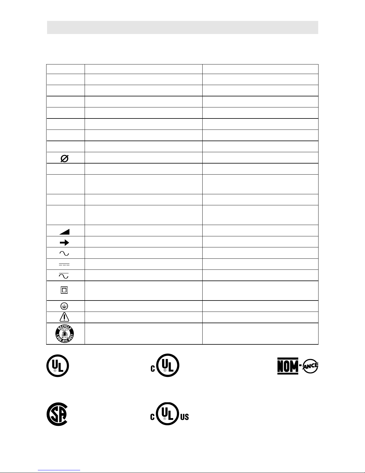
IMPORTANT: Some of the following symbols may be used on your tool. Please study them
and learn their meaning. Proper interpretation of these symbols will allow you to operate the
tool better and safer.
Symbol Name Designation/Explanation
V Volts Voltage (potential)
A Amperes Current
Hz Hertz Frequency (cycles per second)
W Watt Power
kg Kilograms Weight
min Minutes Time
s Seconds Time
Diameter Size of drill bits, grinding wheels, etc.
n
0
No load speed Rotational speed, at no load
.../min Revolutions or reciprocation per minute Revolutions, strokes, surface speed,
orbits etc. per minute
0 Off position Zero speed, zero torque...
1, 2, 3, ... Selector settings Speed, torque or position settings.
I, II, III, Higher number means greater speed
Infinitely variable selector with off Speed is increasing from 0 setting
Arrow Action in the direction of arrow
Alternating current Type or a characteristic of current
Direct current Type or a characteristic of current
Alternating or direct current Type or a characteristic of current
Class II construction Designates Double Insulated
Construction tools.
Earthing terminal Grounding terminal
Warning symbol Alerts user to warning messages
Ni-Cad RBRC seal Designates Ni-Cad battery recycling
program
Symbols
A
0
A
A
0
A
This symbol designates
that this tool is listed by
Underwriters Laboratories.
This symbol designates
that this tool is listed by
the Canadian Standards
Association.
This symbol designates
that this tool is listed to
Canadian Standards by
Underwriters Laboratories.
This symbol
designates
that
this tool
complies
to NOM
Mexican
Standards.
This symbol designates that
this tool is listed by
Underwriters Laboratories,
and listed to Canadian
Standards by Underwriters
Laboratories.
Disconnect battery pack from tool or place the switch in the locked or
off position before making any assembly, adjustments or changing
accessories
. Such preventive safety measures reduce the risk of starting the tool
accidentally.
-
7
-
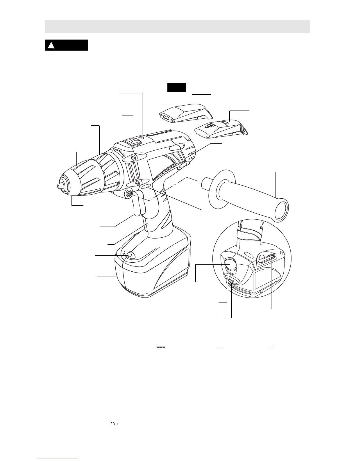
Functional Description and Specifications
!
WARNING
BATTERY
RELEASE BUTTON
BATTERY PACK
RUBBERIZED GRIP
VENTILATION OPENINGS
VARIABLE SPEED
TRIGGER SWITCH
KEYLESS
CHUCK
REVERSING
SWITCH LEVER
FIG. 1
ADJUSTABLE
CLUTCH
CHUCK
SLEEVE
* STUD FINDER
* BIT STORAGE COMPARTMENT
& QUICK REFERENCE GAUGE
* SITE-LIGHT™
* AUXILIARY HANDLE
GEAR SHIFTER
* FORWARD/REVERSE
INDICATOR LIGHTS
BIT AND
STORAGE AREA
* CHARGED CONDITION
INDICATOR LIGHTS
* BUTTON
* NOT AVAILABLE ON ALL MODELS
Tool
Model number 2487 2587 2887
Voltage rating 12 V 14.4 V 18 V
Chuck size
3/8"
3/8" 3/8"
Maximum Capacities
Screw sizes #10 x 4" #12 x 4" 3/8" x 4"
Mild metal 3/8" 3/8" 1/2"
Hard wood 1/2" 9/16" 5/8"
Soft wood 3/4" 1" 1-1/8"
Battery pack SB12A SB14A SB18A
Charger SC114 or SC312 SC114 or SC314 SC118 or SC318
Voltage rating
(all models) 120 V 60 Hz
NOTE: For tool specifications refer to the nameplate on
your tool.
Cordless Drills/Drivers

-8-
Operating Instructions
VARIABLE SPEED CONTROLLED
TRIGGER SWITCH
Your tool is equipped with a variable speed
trigger switch. The tool speed can be
controlled from the minimum to the maximum
nameplate RPM by the pressure you apply to
the trigger. Apply more pressure to increase
the speed and release pressure to decrease
speed. This accurate speed control enables
you to drill without center punching. It also
permits you to use as a power screwdriver.
Bits are available for driving screws as well as
running bolts and nuts.
FORWARD/REVERSING LEVER &
TRIGGER LOCK
Your tool is equipped with a forward/
reversing lever and trigger lock located above
the trigger (Fig. 1). This lever was designed
for changing rotation of the chuck, and for
locking the trigger in an “OFF” position to help
prevent accidental starts and accidental
battery discharge.
* FORWARD/REVERSE INDICATOR LIGHTS
Your tool is equipped with lights which
indicates the rotation of the chuck.
For forward rotation, (with chuck pointed
away from you) move the lever to the far left
and the green indicator will light up.
For reverse rotation move the lever to the far
right and the red indicator light will light up .
To activate trigger lock move lever to the
center off position.
Do not change direction of
rotation until the tool
comes to a complete stop.
Shifting during
rotation of the chuck can cause damage to
the tool.
ADJUSTABLE CLUTCH
Your tool features 26 clutch settings. Output
torque will increase as the clutch ring, is
rotated from 1 to 25. The drill “ ”
position will lock up the clutch to permit
drilling and driving heavyduty work, and also
enables bits to be changed quickly and easily
in the keyless chuck.
BRAKE
When the trigger switch is released it
activates the brake to stop the chuck quickly.
This is especially useful in the repetitive
driving and removal of screws.
GEAR SHIFTING
Your tool is equipped with two separate gear
ranges, low gear and high gear. Low gear
provides high-torque and slower drilling
speeds for heavy duty work or for driving
screws. High gear provides faster speeds for
drilling lighter work. To change speeds slide
switch, to the high or low position.
* AUXILIARY HANDLE
The auxiliary handle will provide additional
control, support and guidance for the tool. The
handle can be positioned on either side of the
tool. To mount, insert mounting bolt into
mounting hole, and simply thread handle onto
bolt until tight.
* SITE-LIGHT™
Your tool is also equipped with a light that
turns on automatically when the switch is
activated for better visibility during operation.
The Site-Light™ is maintenance free and was
designed to last the life of your tool.
* BATTERY CHARGED CONDITION
INDICATOR
The battery is equipped with a charged
condition indicator (Fig.1). The indicator
lights shows the charged condition of the
battery during the working process.
By pressing the button ON, the charged
condition can also be checked when the
battery is removed or when the machine is
not in use.
• • • When all three lights are illuminated,
this indicates the batter pack is fully
Charged.
• • When only two lights illuminate, this
indicates the batter pack is partially charged.
• When only one light illuminates, this
indicates the battery pack is slightly charged.
When no lights illuminate, this indicates the
battery pack is completely discharged.
!
CAUTION
* NOT AVAILABLE ON ALL MODELS
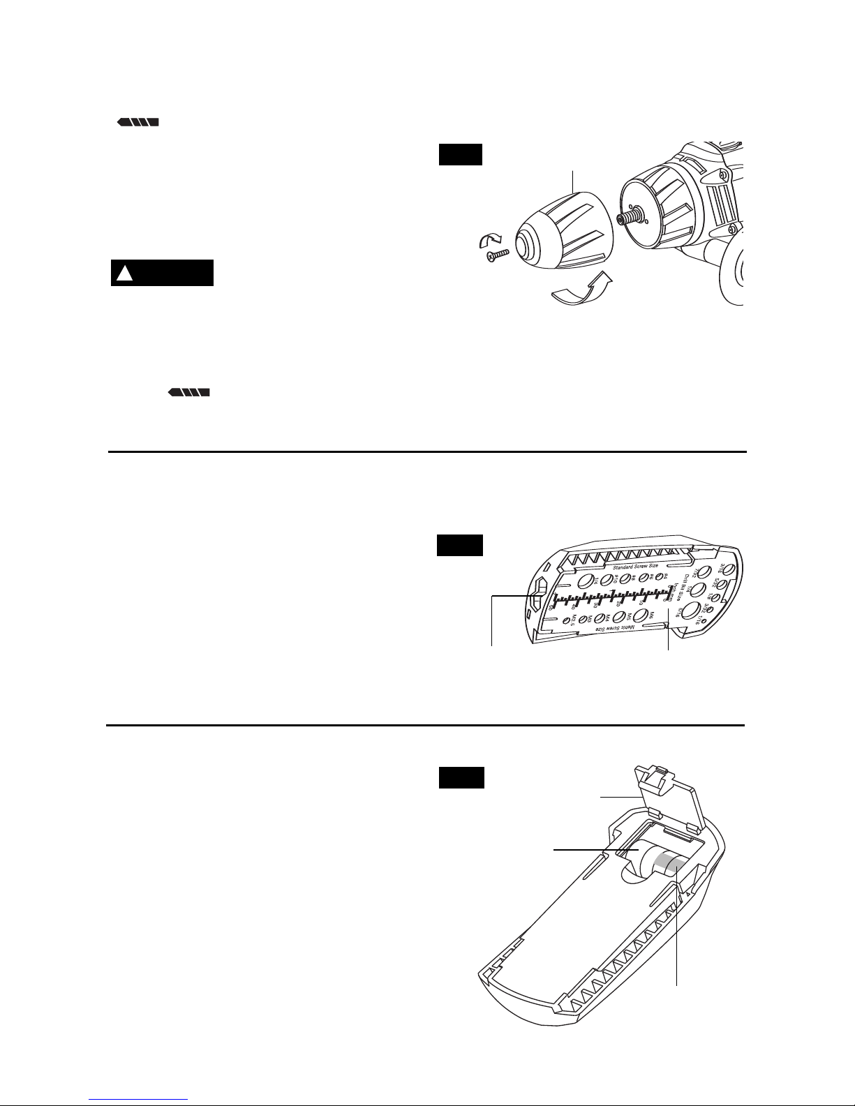
INSERTING BITS
Move reverse switch lever to the center “OFF”
position. Remove battery pack and rotate the
clutch ring to the drill bit symbol
“ ”. Rotate the chuck sleeve counterclockwise viewing from chuck end, and open
chuck to approximate drill bit diameter. Insert
a clean bit up to the drill bit flutes for small
bits, or as far as it will go for large bits. Close
chuck by rotating the chuck sleeve clockwise
and securely tighten by hand
(Fig. 2).
Do not use the power of
the drill while grasping
chuck to loosen or tighten bit.
Friction burn
or hand injury is possible if attempting to
grasp the spinning chuck.
REMOVING CHUCK
Rotate the clutch ring to the drill bit
symbol “ ”. Open the chuck all the way,
remove left-hand thread screw inside chuck
by turning it clockwise. Insert the short arm of
a 3/8" hex key wrench and close jaws on flats
of wrench. Strike long arm of wrench sharply
counterclockwise, remove wrench and
unthread chuck from spindle (Fig. 2).
INSTALLING CHUCK
Always keep the spindle threads, the threads
of the chuck and securing screw free of
debris. To install a chuck, reverse “removing
the chuck” procedure.
-9-
CLOCKWISE
COUNTER
CLOCKWISE
CHUCK
SLEEVE
FIG. 2
* DRILL BIT STORAGE COMPARTMENT
AND QUICK REFERENCE GAUGE
Your tool may be equipped with a bit storage
compartment and quick reference gauge
located on top of your tool (Fig. 3).
To remove, simply slide off the housing
towards the back of the tool.
The quick reference gauge will allow you to
identify the size of drill bits, and standard or
metric screws.
Hex bits can be slid in from the front for
storage.
FIG. 3
QUICK REFERENCE
GAUGE
BIT STORAGE
COMPARTMENT
* STUD FINDER
Your tool may be equipped with a stud finder
located on top of your tool.
To remove, simply slide off the housing
towards the back of the tool.
Before first use, open the battery
compartment door and remove the protective
plastic insert from between the batteries.
Assure proper battery placement as shown in
the compartment and replace the door (Fig.
4). Your stud finder uses four L1154 button
cell batteries.
FIG. 4
BATTERIES
DOOR
PROTECTIVE
PLASTIC INSERT
!
WARNING
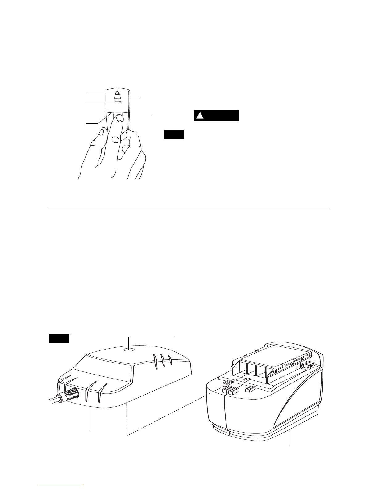
To use, place stud finder flat against the wall
with LEDS pointing up. Be sure to keep your
fingers below the line on the stud finder to
avoid false readings (Fig. 5).
Push and hold button to calibrate and activate
unit (Green LED) (Fig. 5). Slowly slide unit
horizontally across the wall without picking up
or tilting.
The yellow LED indicates you are
approaching a stud.
The red LED indicates stud edge. Mark this
spot.
With the button still depressed, continue
sliding the stud finder in the same direction
until the red LED turns off. This is the studs
other edge. Mark this spot.
The midpoint of the two marks is the center of
the stud.
A fault has occurred when all three LEDS
flash . To correct, simply restart the circuit.
Stud finders can detect
other objects besides
studs, such as electrical wiring and
metal/plastic pipes.
Contact with a “live”
wire will make exposed metal parts of the tool
“live” and shock the operator.
(Studs are normally spaced 16 or 24 inches
apart and are 1-1/2" wide. Beware of anything
closer together or of a different width.) Always
turn off power when working near electrical
wires.
INDICATOR LIGHT
BATTERY PACK
CHARGER
FIG. 6
-10-
FIG. 5
!
WARNING
BUTTON
RED LED
LINE
YELLOW LED
GREEN LED
RELEASING AND INSERTING
BATTERY PACK
Release battery pack from tool by pressing
the battery release button and sliding pack
out of handle base (Fig. 1). To insert battery,
align battery and slide battery pack into tool
until it locks into position. Do not force.
CHARGING BATTERY PACK
(STANDARD CHARGER)
Plug charger cord into your standard power
outlet, then slide battery pack into charger
(Fig. 6). The charger’s green light will turn
“ON”. The green light remains ‘‘ON’’ as long as
charger is plugged in, and does not shut off.
After normal usage, the battery pack requires
approximately 3 hours or less charging time
to become fully charged. If the battery pack
is run-down completely, it may require up to
5 hours charging time to become fully
charged.
When the battery pack is fully charged,
unplug the charger (unless you're charging
another battery pack) and slide the battery
pack back into the tool handle.
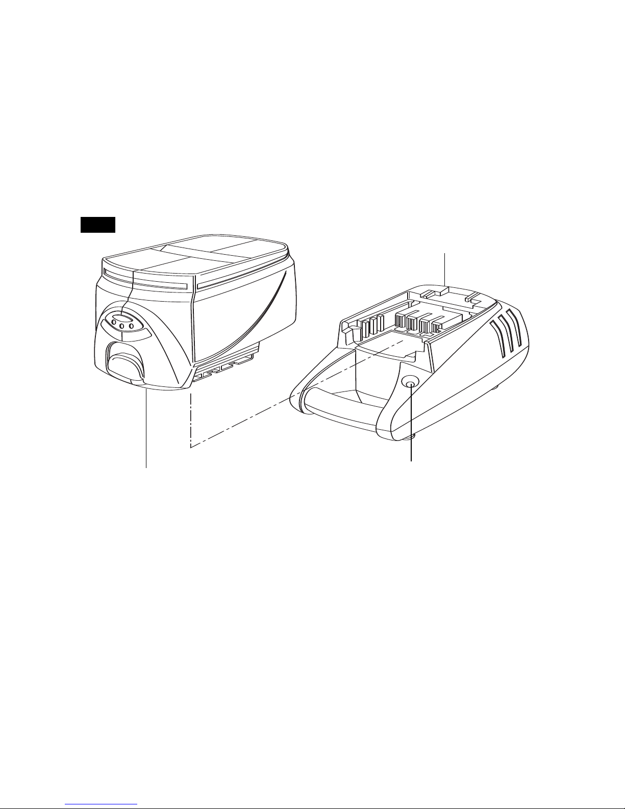
Plug charger cord into your standard power
outlet, then slide the battery pack into charger
(Fig. 7).
The charger’s green indicator will begin to
“BLINK”. This indicates that the battery is
receiving a fast charge. Fast-charging will
automatically stop when the battery pack is
fully charged.
When the indicator light stops “BLINKING”
(and becomes a steady green light) fast
charging is complete.
When you begin the charging process of the
battery pack, a steady green light could also
mean the battery pack is too hot or too cold.
The purpose of the light is to indicate that the
battery pack is fast-charging. It does not
indicate the exact point of full charge. The
light will stop blinking in less time if the
battery pack was not completely discharged.
When the battery pack is fully charged,
unplug the charger (unless you're charging
another battery pack) and slip the battery
pack back into the tool handle.
-
11
-
CHARGING BATTERY PACK (FAST CHARGER)
INDICATOR
LIGHT
CHARGER
BATTERY PACK
FIG. 7
IMPORTANT CHARGING NOTES
1. The battery pack accepts only about 80%
of its maximum capacity with its first few
charge cycles. However, after the first few
charge cycles, the battery will charge to full
capacity.
2. The charger was designed to fast charge
the battery only when the battery
temperature is between 40˚F (4˚C) and
105˚F (41˚C).
3. A substantial drop in operating time per
charge may mean that the battery pack is
nearing the end of its life and should be
replaced.
4. If you anticipate long periods (i.e. a month
or more) of non-use of your tool, it is best to
run your tool down until it is fully discharged
before storing your battery pack. After a long
period of storage, the capacity at first recharge
will be lower. Normal capacity will be restored
in two or three charge/discharge cycles.
Remember to unplug charger during storage
period.
5. If battery does not charge properly:
a. Check for voltage at outlet by plugging
in some other electrical device.
b. Check to see if outlet is connected to a
light switch which turns power “off” when
lights are turned off.
c. Check battery pack terminals for dirt.
Clean with cotton swab if necessary.
d.
If you still do not get proper charging,
take or send tool, battery pack and charger
to your local Skil Service Center.
Note: Use of charger’s or battery packs not
sold by Skil will void the warranty.
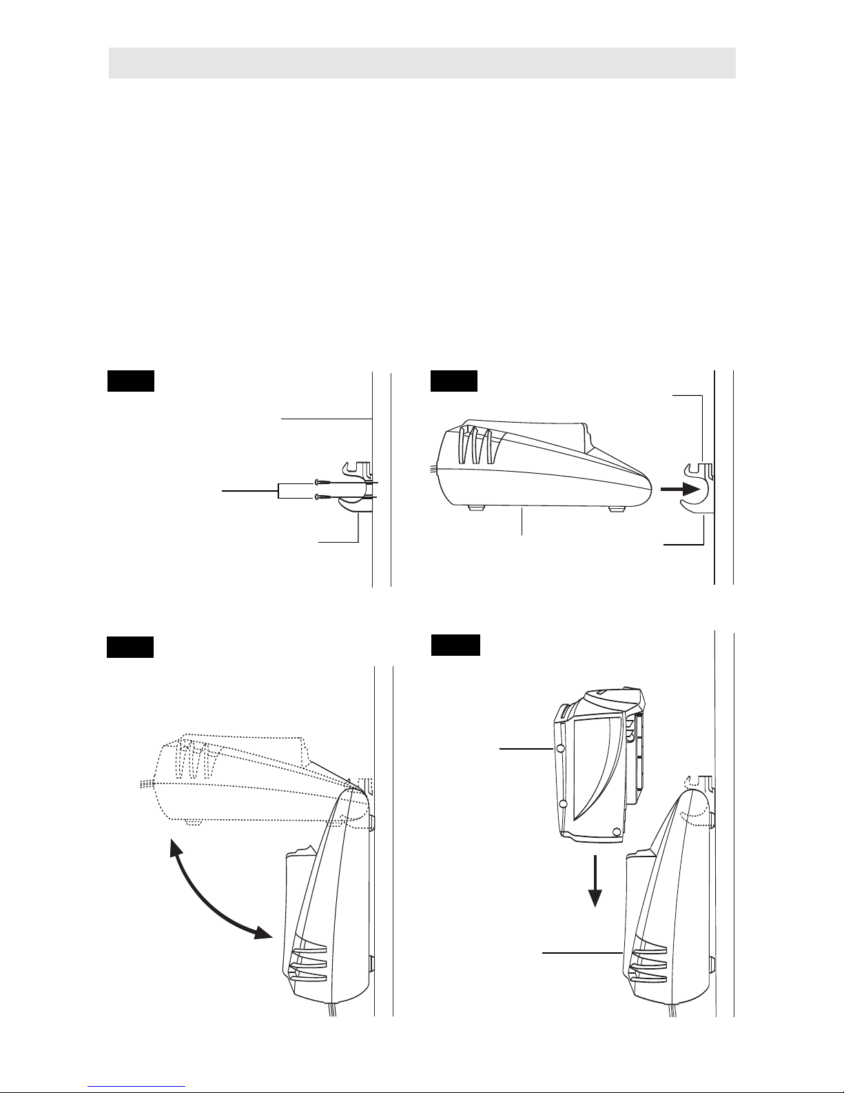
MOUNTING CHARGER TO
A VERTICAL SURFACE
For convenience, your charger was designed
so it may be used on a flat horizontal surface,
or it may be mounted onto a vertical surface.
The mounting clip also features a bit storage on
top of the clip.
1. Select mounting location near a electrical
outlet so that the plug will reach the outlet.
Check for studs or other support.
2. Using a pencil, mark two places on the
surface in a vertical line about 3/4" apart.
3. Secure mounting clip to the vertical surface
using two #8 round head screws (Fig. 8).
4. Remove battery pack from charger before
mounting.
5. Insert handle of charger into the mounting
clip in the horizontal position (Fig 9).
6. Gently lower the charger into the vertical
position until it lays flat against the vertical
surface and locks the charger into the mounting
the clip (Fig. 10).
7. To remove charger when desired, raise the
charger back into the horizontal position to
unlock the charger, then remove charger from
the mounting clip (Fig. 10).
8. To charge the battery pack, simply slide
battery pack into charger (Fig. 11).
-
12
-
Mounting Charger
VERTICAL
SURFACE
MOUNTING
CLIP
#8 ROUND
HEAD WOOD
SCREWS
CHARGER
TO LOCK
MOUNTING
CLIP
TO
UNLOCK
BATTERY
PACK
CHARGER
BIT STORAGE
COMPARTMENT
FIG. 8 FIG. 9
FIG. 10
FIG. 11
DRILL BITS
Always inspect drill bits for excessive wear.
Use only bits that are sharp and in good
condition.
TWIST BITS: Available with straight and
reduced shanks for wood and light duty metal
drilling. High speed bits cut faster and last
longer on hard materials.
CARBIDE TIPPED BITS: Used for drilling
stone, concrete, plaster, cement and other
unusually hard nonmetals. Use continuous
heavy feed pressure when employing carbide
tip bits.
DRILLING WOOD
Be certain workpiece is clamped or anchored
firmly. Always apply pressure in a straight line
with the drill bit. Maintain enough pressure to
keep the drill “biting”.
When drilling holes in wood, twist bits can be
used. Twist bits may overheat unless pulled out
frequently to clear chips from flutes.
Use a “back-up” block of wood for work that is
likely to splinter, such as thin materials.
You will drill a cleaner hole if you ease up on
the pressure just before the bit breaks through
the wood. Then complete the hole from the
back side.
You will extend the life of your bits and do
neater work if you always put the bit in
contact with the work before pulling the
trigger. During the operation, hold the tool
firmly and exert light, steady pressure. Too
much pressure at low speed will stall the
tool. Too little pressure will keep the bit from
cutting and cause excess friction by sliding
over the surface. This can be damaging to
both tool and bit.
DRILLING WITH VARIABLE SPEED
The trigger controlled variable speed feature
will eliminate the need for center punches in
hard materials. The variable speed trigger
allows you to slowly increase RPM. By using
a slow starting speed, you are able to keep
the bit from “wandering”. You can increase
the speed as the bit “bites” into the work by
squeezing the trigger.
DRIVING WITH VARIABLE SPEED
Variable speed drills will double as a power
screwdriver by using a screwdriver bit in the
drill mode. The technique is to start slowly,
increasing the speed as the screw runs
down. Set the screw snugly by slowing to a
stop. Prior to driving screws, pilot and
clearance holes should be drilled.
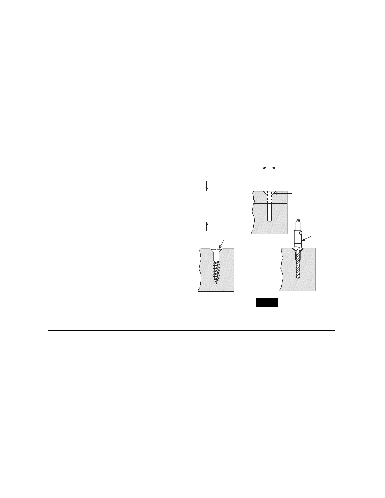
FASTENING WITH SCREWS
This procedure shown in (Fig. 12) will enable
you to fasten materials together with your
Cordless Drill/Screwdriver without stripping,
splitting or separating the material.
First, clamp the pieces together and drill the
first hole 2/3 the diameter of the screw. If the
material is soft, drill only 2/3 the proper
length. If it is hard, drill the entire length.
Second, unclamp the pieces and drill the
second hole the same diameter as the screw
shank in the first or top piece of wood.
Third, if flat head screw is used, countersink
the hole to make the screw flush with the
surface. Then, simply apply even pressure
when driving the screw. The screw shank
clearance hole in the first piece allows the
screw head to pull the pieces tightly together.
The adjustable screw drill accessory will do
all of these operations quickly and easily.
Screw drills are available for screw sizes No.
6, 8, 10 and 12.
2. Drill same
diameter as
screw shank.
3. Countersink
same diameter
as screw head.
1. Drill 2/3 diameter and
2/3 of screw length for
soft materials, full
length for hard
materials.
Adjustable
Screw
Drill
Screw
Apply a slight
even pressure
when driving
screws.
FASTENING
WITH SCREWS
FIG. 12
-
13
-
Operating Tips

DRILLING METAL
There are two rules for drilling hard materials.
First, the harder the material, the greater the
pressure you need to apply to the tool. Second,
the harder the material, the slower the speed.
Here are a couple of tips for drilling in metal.
Lubricate the tip of the bit occasionally with
cutting oil except when drilling soft metals such
as aluminum, copper or cast iron. If the hole to
be drilled is fairly large, drill a smaller hole first,
then enlarge to the required size, it’s often
faster in the long run. Maintain enough
pressure to assure that the bit does not just
spin in the hole. This will dull the bit and greatly
shorten its life.
DRILLING MASONRY
Soft materials such as brick are relatively easy
to drill. Concrete however, will require much
more pressure to keep the bit from spinning. Be
sure to use carbide tip bits for all masonry work.
Before using an accessory,
be certain that its maximum
safe operating speed is not exceeded by the
nameplate speed of the tool. Do not exceed
the recommended wheel diameter.
RUNNING NUTS AND BOLTS
Variable speed control must be used with
caution for driving nuts and bolts with socket
set attachments. The technique is to start
slowly, increasing speed as the nut or bolt runs
down. Set the nut or bolt snugly by slowing the
drill to a stop. If this procedure is not followed,
the tool will have a tendency to torque or twist
in your hands when the nut or bolt seats.
!
WARNING
-14-
Service
NO USER SERVICEABLE
PARTS INSIDE. Preventive
maintenance performed by unauthorized
personnel may result in misplacing of
internal wires and components which
could cause serious hazard.
We recommend that all tool service be performed by a
Skil Factory Service Center or Authorized Skil
Service Station. SERVICEMEN: Disconnect
tool and/or charger from power source before
servicing.
BATTERIES
Be alert for battery packs that are nearing
their end of life.
If you notice decreased
tool performance or significantly shorter
running time between charges then it is time
to replace the battery pack. Failure to do so
can cause the tool to operate improperly or
damage the charger.
Long term battery storage should be in
the discharged state.
Battery packs last
longer and re-charge better when they are
stored discharged. Remember to fully recharge battery packs before using after
prolonged storage.
TOOL LUBRICATION
Your Skil tool has been properly lubricated
and is ready for use.
D.C. MOTORS
The motor in your tool has been engineered
for many hours of dependable service. To
maintain peak efficiency of the motor, we
recommend it be examined every six months.
Only a genuine Skil replacement motor
specially designed for your tool should be
used.
Cleaning
To avoid accidents, always
disconnect the tool and/or
charger from the power supply before
cleaning.
The tool may be cleaned most
effectively with compressed dry air.
Always
wear safety goggles when cleaning tools
with compressed air.
Ventilation openings and switch levers must
be kept clean and free of foreign matter. Do
not attempt to clean by inserting pointed
objects through opening.
Certain cleaning agents
and solvents damage
plastic parts.
Some of these are: gasoline,
carbon tetrachloride, chlorinated cleaning
solvents, ammonia and household detergents
that contain ammonia.
!
WARNING
!
WARNING
Maintenance
!
CAUTION
 Loading...