

Page 1

Page 2
SAFETY WARNING
Disregarding any of the safety precautions and instructions contained in this Operator’s Guide, Safety Handbook, Safety Video or
on-product warnings may result in injury, including the possibility
of death.
This Operator’s Guide , Safety Handbook and Safety Video should
remain with the unit at time of resale.
In USA, products are distributed by Bombardier Motor Corporation
of America. In Canada, products are distributed by Bombardier Inc.
The following are trademarks of Bombardier Inc. or its subsidiaries.
BOMBARDIER
ROTAX
DESS
®
TM
®
Kleen-Flo* is a trademark of Kleen-Flo Tumbler Industries Ltd.
Printed in Canada (Mmo2002-003a.fm GM)
®
are registered trademarks and TM are trademarks of Bombardier Inc. or its subsidiaries.
©
2001 Bombardier Inc. All rights reserved.
MACH Z
TM
CK3
TM
DPM
®
SKI-DOO®
TM
RER
Page 3

2002 SKI-DOO OPERATOR’S GUIDE
This guide is applicable to CK3TM series:
Mach Z
®
STD
Mach Z Tech Plus
1
Page 4

FOREWORD
Congratulations on your purchase of a new SKI-DOO snowmobile.
Whatever model you have chosen, it is backed by the Bombardier
warranty and a network of authorized SKI-DOO snowmobile dealers
ready to provide the parts, service or accessories you may require.
The Operator’s Guide and the Safety Handbook have been prepared
to acquaint the owner/operator and passenger of a new snowmobile
with the various snowmobile controls, maintenance and safe operating instructions. Each is indispensable for the proper use of the product.
Identifies an instruction which if not followed, may cause injuries including the possibility of death.
CAUTION: Denotes an instruction which if not followed, may damage the vehicle and/or components.
Although the mere reading of such information does not eliminate
the hazard, the understanding and application of the information will
promote the correct use of the vehicle.
Your dealer is committed to your satisfaction. He has taken training
to perform the initial set-up and inspection of your snowmobile as
well as completed the final adjustment required to suit your specific
weight and riding environment before you took possession. At delivery, your dealer would have explained the snowmobile controls and
provided you with a brief explanation of the various suspension adjustments. We trust you have taken full advantage of this! If you need
more complete servicing information, please ask your dealer about
the proper model-year Ski-Doo Shop Manual.
WARNING
At delivery, you were also informed of the warranty coverage and
completed the Warranty Registration Form which is to be sent to us
for processing.
The information and components/system descriptions contained in
this guide are correct at time of publication.
We also reserve the right at any time to discontinue or change specifications, designs, features, models or equipment without incurring
obligation.
The illustrations show the typical construction of the different assemblies and, in all cases, may not reproduce the full detail or exact shape
of the parts shown, however, they represent parts which have the
same or a similar function.
2
Page 5

It is understood that this guide may be translated into another language. In the event of any discrepancy, the English version shall prevail.
Most components of this snowmobile are built with parts dimensioned in the metric system. Most fasteners are metric and must not
be replaced by customary fasteners or vice versa.
We recommend genuine Bombardier products for replacement parts
and accessories. They’ve been specially designed for your vehicle and
manufactured to meet of Bombardier demanding standards.
A Shop Manual can be obtained for complete service, maintenance
and more repair information.
3
Page 6

TABLE OF CONTENTS
SAFETY MEASURES .......................................................... 7
BOMBARDIER LIMITED WARRANTY NORTH AMERICA:
2002 SKI-DOO
BOMBARDIER LIMITED WARRANTY INTERNATIONAL:
2002 SKI-DOO
FREQUENTLY ASKED QUESTIONS ....................................... 14
AUTHORIZED SKI-DOO DEALERS ......................................... 16
HOW TO IDENTIFY YOUR SNOWMOBILE ............................ 16
Vehicle Description Decal.......................................................... 16
Serial Numbers.......................................................................... 17
ON-VEHICLE IMPORTANT INSTRUCTIONS.......................... 19
CONTROLS/INSTRUMENTS/EQUIPMENT ........................... 23
1) Throttle Lever ...................................................................... 25
2) Brake Lever ......................................................................... 25
3) Parking Brake Button........................................................... 25
4) Injection Oil Level/Parking Brake Pilot Lamp (Red).............. 26
5) Handlebar ............................................................................ 26
6) Reverse Button ................................................................... 27
7) Tether Cut-Out Switch ........................................................ 28
8) DESS Pilot Lamp ................................................................. 30
9) Engine Cut-Out Switch........................................................ 31
10) Headlamp Dimmer Switch .................................................. 32
11) High Beam Pilot Lamp (Blue) .............................................. 32
12) Rewind Starter Handle ........................................................ 32
13) Choke Lever ........................................................................ 33
14) Speedometer....................................................................... 33
15) Odometer ............................................................................ 33
16) Trip Meter............................................................................ 34
17) Trip Meter Reset Button ..................................................... 34
18) Tachometer ......................................................................... 34
19) Temperature Gauge ............................................................ 35
20) Electric Fuel Level Gauge.................................................... 36
21) Fuel Tank Cap...................................................................... 36
22) Heated Grip Switch ............................................................. 37
23) Heated Throttle Lever Switch ............................................. 37
24) Hood Latches ...................................................................... 37
25) Adjustable Toeholds ............................................................ 38
®
SNOWMOBILES............................................ 8
®
SNOWMOBILES............................................ 11
4
Page 7

26) Adjustable Handlebar ........................................................... 39
27) Adjustable Windshield ......................................................... 40
28) Hood Grills ........................................................................... 41
29) Fuel Shut-Off Valve .............................................................. 42
30) Storage Compartment ......................................................... 42
31) Tool Box ............................................................................... 43
32) Spark Plug Holder ................................................................ 43
33) Spare Drive Belt Holder ....................................................... 44
34) Fuse ..................................................................................... 45
35) Front Grab Handles/Front Bumper....................................... 45
36) Adjustable Suspensions ....................................................... 46
General....................................................................................... 47
Guidelines to Adjust Suspension ............................................... 48
TROUBLESHOOTING CHART.................................................. 63
In Deep Snow ............................................................................ 63
FUEL AND OIL .......................................................................... 64
Recommended Fuel................................................................... 64
Recommended Oil ..................................................................... 65
COLD WEATHER CARBURETION MODIFICATIONS ............. 66
BREAK-IN PERIOD .................................................................... 66
Engine ........................................................................................ 66
Belt............................................................................................. 66
10-Hour Inspection..................................................................... 66
PRE-OPERATION CHECK ......................................................... 67
PRE-OPERATION CHECK LIST ................................................ 68
OPERATING INSTRUCTIONS .................................................. 69
Principle of Operation ................................................................ 69
Starting the Engine .................................................................... 70
Emergency Starting ................................................................... 71
Shutting Off the Engine ............................................................. 73
VEHICLE WARM-UP ................................................................. 73
POST-OPERATION CARE......................................................... 74
SPECIAL OPERATIONS ............................................................ 74
Riding at High Altitudes ............................................................. 74
Engine Overheating ................................................................... 74
Fuel Flooded Engine .................................................................. 74
Rear Suspension Slider Shoe Starts Sticking............................. 74
5
Page 8

PERIODIC MAINTENANCE CHART......................................... 75
FLUID LEVELS.......................................................................... 77
Brake System ............................................................................ 77
Chaincase Oil Level ................................................................... 78
Oil Injection System .................................................................. 79
Cooling System ......................................................................... 80
MAINTENANCE ....................................................................... 81
Vehicle Cleaning and Protection................................................ 81
Belt Guard Removal and Installation ......................................... 82
Drive Belt Removal/Installation ................................................. 84
Drive Chain Tension .................................................................. 88
TRA Drive Pulley Adjustment .................................................... 88
Drive Belt Condition .................................................................. 91
Brake Condition ......................................................................... 91
Brake Adjustment...................................................................... 91
Rear Suspension Condition ....................................................... 91
Suspension Stopper Strap Condition......................................... 91
Track Condition.......................................................................... 91
Track Tension and Alignment .................................................... 92
Steering and Front Suspension Mechanism ............................. 96
Wear and Condition of Skis and Runners.................................. 96
Exhaust System ........................................................................ 97
Air Filter Cleaning ...................................................................... 97
Headlight Beam Aiming............................................................. 100
Bulb Replacement ..................................................................... 100
TOWING THE VEHICLE ........................................................... 103
TRANSPORTING THE VEHICLE .............................................. 103
STORAGE AND PRE-SEASON PREPARATION ..................... 103
Storage ...................................................................................... 103
Pre-Season Preparation ............................................................. 103
TROUBLESHOOTING .............................................................. 104
SPECIFICATIONS ..................................................................... 108
CHANGE OF ADDRESS OR OWNERSHIP.............................. 110
6
Page 9

SAFETY MEASURES
Observe the Following Warnings:
For vehicles with a parking brake, always engage brake when ve-
hicle is not in use.
Throttle mechanism should be checked for free movement before
starting engine.
In an emergency, the snowmobile engine can be stopped by acti-
vating the engine cut-out switch or pulling the tether cord.
Engine should be running only when belt guard is secured in place.
Never run the engine without drive belt installed. Running an unloaded engine such as without drive belt or with track raised, can
prove to be dangerous.
Never run the engine with the hood opened or removed.
Maintain your snowmobile in top mechanical condition at all times.
Your snowmobile is not designed to be operated on public streets,
roads or highways. In most States and Provinces, it is considered
an illegal operation.
Do not lubricate throttle and/or brake cables and housings.
Only perform procedures as detailed in this guide. Unless other-
wise specified, engine should be turned OFF and cold for all lubrication, adjustment and maintenance procedures.
Some snowmobiles are designed for the driver only and no provi-
sions have been made for a passenger.
The performance of this snowmobile may significantly exceed that
of other snowmobiles you have operated. Therefore, use by novice or inexperienced operators is not recommended.
The engine and components used in a particular model should not
be used on other models. Use of Rotax
®
snowmobile engines in
other than SKI-DOO snowmobiles is not recommended or authorized by Bombardier Inc.
Do not stud the track.
Reverse models only: These snowmobiles are capable of a fast
reverse. Always remain seated and apply the brake before shifting.
Come to a complete stop before selecting reverse gear. Ensure
the path behind is clear of obstacles or bystanders. Fast reverse
could result in loss of stability.
7
Page 10

BOMBARDIER LIMITED WARRANTY NORTH
AMERICA: 2002 SKI-DOO
1. SCOPE OF THE LIMITED WARRANTY
BOMBARDIER INC. (hereinafter “BOMBARDIER”) warrants its 2002 SKI-DOO
snowmobiles from defects in material or workmanship for the period described
below.
All genuine BOMBARDIER parts and accessories, installed by an authorized
BOMBARDIER dealer (as hereinafter defined) at the time of delivery of the 2002
SKI-DOO snowmobile, carry the same warranty as that of the snowmobile.
Use of the product for racing or any other competitive activity, at any point,
even by a prior owner will render this warranty null and void.
2. WARRANTY COVERAGE PERIOD
This warranty will be in effect FROM THE DATE OF DELIVERY TO THE FIRST
RETAIL CONSUMER or the date the product is first put into use, whichever
occurs first and for a period of:
a. TWELVE (12) CONSECUTIVE MONTHS, for private use owners. The war-
ranty coverage period on a snowmobile delivered between June 1
December 1
or
b. TWELVE (12) CONSECUTIVE MONTHS, for commercial use owners. The
warranty coverage period on a snowmobile delivered between June 1
December 1
The repair or replacement of parts or the performance of service under this warranty does not extend the life of this warranty beyond its original expiration date.
st
of a given year will expire December 1st of the following year;
st
of a given year will expire December 1st of the following year.
®
SNOWMOBILES
st
and
st
and
3. CONDITIONS TO HAVE WARRANTY COVERAGE
This warranty coverage is available only on 2002 SKI-DOO snowmobile purchased as new and unused by its first owner from a BOMBARDIER dealer
authorized to distribute SKI-DOO products in the country in which the sale
occurred (hereinafter “BOMBARDIER dealer”), and then only after the BOMBARDIER specified pre-delivery inspection process is completed and documented. Warranty coverage only becomes available upon proper registration
of the product by a BOMBARDIER dealer. Such limitations are necessary in
order to allow BOMBARDIER to preserve both the safety of its products, and
also that of its consumers and the public.
Routine maintenance outlined in the Operator’s Guide must be timely per-
formed in order to maintain warranty coverage. BOMBARDIER reserves the
right to make warranty coverage contingent upon proof of proper maintenance.
4. WHAT TO DO TO OBTAIN WARRANTY COVERAGE
The customer must notify a servicing BOMBARDIER dealer within two (2) days
of the appearance of a defect, and provide it with reasonable access to the
product and reasonable opportunity to repair it. The customer must also present
to the BOMBARDIER dealer, proof of purchase of the product and must sign
the repair/work order prior to the start of the repair in order to validate the
warranty repair. All parts replaced under this limited warranty become the property of BOMBARDIER.
5. WHAT BOMBARDIER WILL DO
BOMBARDIER’s obligations under this warranty are limited to, at its sole dis-
cretion, repairing parts found defective under normal use, maintenance and
service, or replacing such parts with new genuine BOMBARDIER parts without
charge for parts and labor, at any authorized BOMBARDIER dealer.
BOMBARDIER reserves the right to improve or modify products from time to time
without assuming any obligation to modify products previously manufactured.
8
Page 11

6. EXCLUSIONS - ARE NOT WARRANTED
• Normal wear and tear;
• Routine maintenance items, tune ups, adjustments;
• Damage caused by failure to provide proper maintenance and/or storage, as
described in the Operator’s Guide;
• Damage resulting from removal of parts, improper repairs, service, maintenance, modifications or use of parts not manufactured or approved by BOMBARDIER or resulting from repairs done by a person that is not an authorized
servicing BOMBARDIER dealer;
• Damage caused by abuse, abnormal use, neglect, use of the product on
surfaces other than snow, or operation of the product in a manner inconsistent with the recommended operation described in the Operator’s Guide;
• Damage resulting from accident, submersion, fire, theft, vandalism or any act
of God;
• Operation with fuels, oils or lubricants which are not suitable for use with
the product (see the Operator’s Guide);
• Snow or water ingestion;
• Incidental or consequential damages, or damages of any kind including with-
out limitation towing, storage, telephone, rental, taxi, inconvenience, insurance coverage, loan payments, loss of time, loss of income; and
• Damage resulting from tracks which have been studded.
7. LIMITATIONS OF LIABILITY
THIS WARRANTY IS EXPRESSLY GIVEN AND ACCEPTED IN LIEU OF ANY
AND ALL OTHER WARRANTIES, EXPRESSED OR IMPLIED, INCLUDING
WITHOUT LIMITATION ANY WARRANTY OF MERCHANTABILITY OR FITNESS FOR A PARTICULAR PURPOSE. TO THE EXTENT THAT THEY CANNOT BE DISCLAIMED, THE IMPLIED WARRANTIES ARE LIMITED IN DURATION TO THE LIFE OF THE EXPRESS WARRANTY. INCIDENTAL AND
CONSEQUENTIAL DAMAGES ARE EXCLUDED FROM COVERAGE UNDER
THIS WARRANTY. SOME STATES/PROVINCES DO NOT ALLOW FOR THE
DISCLAIMERS, LIMITATIONS AND EXCLUSIONS IDENTIFIED ABOVE, AS
A RESULT, THEY MAY NOT APPLY TO YOU. THIS WARRANTY GIVES
YOU SPECIFIC RIGHTS, AND YOU MAY ALSO HAVE OTHER LEGAL
RIGHTS WHICH MAY VARY FROM STATE TO STATE, OR PROVINCE TO
PROVINCE.
Neither the distributor, any BOMBARDIER dealer nor any other person has
been authorized to make any affirmation, representation or warranty regarding
the product, other than those contained in this limited warranty, and if made,
shall not be enforceable against BOMBARDIER.
BOMBARDIER reserves the right to modify this warranty at any time, being
understood that such modification will not alter the warranty conditions applicable to the products sold while this warranty is in effect.
8. TRANSFER
If the ownership of a product is transferred during the warranty coverage period, this warranty shall also be transferred and be valid for the remaining coverage period provided that BOMBARDIER is notified of such transfer of ownership in the following way:
a. The former owner contacts BOMBARDIER (at the phone number provided
below) or an authorized BOMBARDIER dealer and gives the coordinates of
the new owner; or
b. BOMBARDIER or an authorized BOMBARDIER dealer receives a proof that
the former owner agreed to the transfer of ownership, in addition to the
coordinates of the new owner.
9
Page 12

9. CONSUMER ASSISTANCE
a. In the event of a controversy or a dispute in connection with this BOMBAR-
DIER LIMITED WARRANTY, BOMBARDIER suggests that you try to resolve
the issue at the dealership level. We recommend discussing the issue with
the authorized dealer’s service manager or owner.
b. If the issue has not yet been resolved, please submit your complaint in
writing or call the appropriate number below:
In Canada: In USA:
BOMBARDIER INC. BOMBARDIER MOTOR
RECREATIONAL PRODUCTS CORPORATION OF AMERICA
SKI-DOO
CUSTOMER ASSISTANCE CENTER SKI-DOO
®
RECREATIONAL PRODUCTS
®
VALCOURT QC J0E 2L0 CUSTOMER ASSISTANCE CENTER
Tel: (819) 566-3366 P.O. BOX 8035
7575 BOMBARDIER COURT
WAUSAU WI 54402-8035
Tel: (715) 848-4957
© 2000 Bombardier Inc. All rights reserved
® Registered trademark of Bombardier Inc.
10
Page 13

BOMBARDIER LIMITED WARRANTY
INTERNATIONAL: 2002 SKI-DOO
®
SNOWMOBILES
1. SCOPE OF THE LIMITED WARRANTY
BOMBARDIER INC. (hereinafter “BOMBARDIER”) warrants its 2002 SKI-DOO
snowmobiles from defects in material or workmanship for the period described
below.
All genuine BOMBARDIER parts and accessories, installed by an authorized
BOMBARDIER distributor/dealer (as hereinafter defined) at the time of delivery
of the 2002 SKI-DOO snowmobile, carry the same warranty as that of the snowmobile.
Use of the product for racing or any other competitive activity, at any point, even
by a prior owner will render this warranty null and void.
2. WARRANTY COVERAGE PERIOD
This warranty will be in effect FROM THE DATE OF DELIVERY TO THE FIRST
RETAIL CONSUMER or the date the product is first put into use, whichever
occurs first and for a period of:
a. TWELVE (12) CONSECUTIVE MONTHS, for private use owners. The war-
ranty coverage period on a snowmobile delivered between June 1
December 1
or
b. TWELVE (12) CONSECUTIVE MONTHS, for commercial use owners. The
warranty coverage period on a snowmobile delivered between June 1
December 1
The repair or replacement of parts or the performance of service under this
warranty does not extend the life of this warranty beyond its original expiration
date.
st
of a given year will expire December 1st of the following year;
st
of a given year will expire December 1st of the following year.
st
and
st
and
3. CONDITIONS TO HAVE WARRANTY COVERAGE
This warranty coverage is available only on 2002 SKI-DOO snowmobile purchased as new and unused by its first owner from a BOMBARDIER distributor/
dealer authorized to distribute SKI-DOO products in the country in which the
sale occurred (hereinafter “BOMBARDIER distributor/dealer”), and then only
after the BOMBARDIER specified pre-delivery inspection process is completed
and documented. Warranty coverage only becomes available upon proper registration of the product by a BOMBARDIER dealer. Such limitations are necessary in order to allow BOMBARDIER to preserve both the safety of its products,
and also that of its consumers and the public.
Routine maintenance outlined in the Operator’s Guide must be timely per-
formed in order to maintain warranty coverage. BOMBARDIER reserves the
right to make warranty coverage contingent upon proof of proper maintenance.
4. WHAT TO DO TO OBTAIN WARRANTY COVERAGE
The customer must notify a servicing BOMBARDIER distributor/dealer within
two (2) days of the appearance of a defect, and provide it with reasonable access
to the product and reasonable opportunity to repair it. The customer must also
present to the BOMBARDIER dealer, proof of purchase of the product and
must sign the repair/work order prior to the start of the repair in order to validate
the warranty repair. All parts replaced under this limited warranty become the
property of BOMBARDIER.
11
Page 14

5. WHAT BOMBARDIER WILL DO
BOMBARDIER’s obligations under this warranty are limited to, at its sole dis-
cretion, repairing parts found defective under normal use, maintenance and
service, or replacing such parts with new genuine BOMBARDIER parts without
charge for parts and labor, at any authorized BOMBARDIER distributor/dealer.
BOMBARDIER reserves the right to improve or modify products from time to
time without assuming any obligation to modify products previously manufactured.
6. EXCLUSIONS - ARE NOT WARRANTED
• Normal wear and tear;
• Routine maintenance items, tune ups, adjustments;
• Damage caused by failure to provide proper maintenance and/or storage, as
described in the Operator’s Guide;
• Damage resulting from removal of parts, improper repairs, service, maintenance, modifications or use of parts not manufactured or approved by BOMBARDIER or resulting from repairs done by a person that is not an authorized
servicing BOMBARDIER dealer;
• Damage caused by abuse, abnormal use, neglect, use of the product on
surfaces other than snow, or operation of the product in a manner inconsistent with the recommended operation described in the Operator’s Guide;
• Damage resulting from accident, submersion, fire, theft, vandalism or any act
of God;
• Operation with fuels, oils or lubricants which are not suitable for use with the
product (see the Operator’s Guide);
• Snow or water ingestion;
• Incidental or consequential damages, or damages of any kind including with-
out limitation towing, storage, telephone, rental, taxi, inconvenience, insurance coverage, loan payments, loss of time, loss of income; and
• Damage resulting from tracks which have been studded.
7. LIMITATIONS OF LIABILITY
THIS WARRANTY IS EXPRESSLY GIVEN AND ACCEPTED IN LIEU OF ANY
AND ALL OTHER WARRANTIES, EXPRESSED OR IMPLIED, INCLUDING
WITHOUT LIMITATION ANY WARRANTY OF MERCHANTABILITY OR FITNESS FOR A PARTICULAR PURPOSE. TO THE EXTENT THAT THEY CANNOT BE DISCLAIMED, THE IMPLIED WARRANTIES ARE LIMITED IN DURATION TO THE LIFE OF THE EXPRESS WARRANTY. INCIDENTAL AND
CONSEQUENTIAL DAMAGES ARE EXCLUDED FROM COVERAGE UNDER
THIS WARRANTY. SOME STATES/PROVINCES DO NOT ALLOW FOR THE
DISCLAIMERS, LIMITATIONS AND EXCLUSIONS IDENTIFIED ABOVE, AS
A RESULT, THEY MAY NOT APPLY TO YOU. THIS WARRANTY GIVES YOU
SPECIFIC RIGHTS, AND YOU MAY ALSO HAVE OTHER LEGAL RIGHTS
WHICH MAY VARY FROM STATE TO STATE, OR PROVINCE TO PROVINCE.
Neither the distributor, any BOMBARDIER dealer nor any other person has been
authorized to make any affirmation, representation or warranty regarding the
product, other than those contained in this limited warranty, and if made, shall
not be enforceable against BOMBARDIER.
BOMBARDIER reserves the right to modify this warranty at any time, being
understood that such modification will not alter the warranty conditions applicable to the products sold while this warranty is in effect.
12
Page 15

8. TRANSFER
If the ownership of a product is transferred during the warranty coverage period, this warranty shall also be transferred and be valid for the remaining coverage period provided that BOMBARDIER is notified of such transfer of ownership in the following way:
a. The former owner contacts BOMBARDIER or an authorized BOMBARDIER
distributor/dealer and gives the coordinates of the new owner; or
b. BOMBARDIER or an authorized BOMBARDIER distributor/dealer receives a
proof that the former owner agreed to the transfer of ownership, in addition
to the coordinates of the new owner.
9. CONSUMER ASSISTANCE
a. In the event of a controversy or a dispute in connection with this BOMBAR-
DIER LIMITED WARRANTY, BOMBARDIER suggests that you try to resolve
the issue at the distributorship/dealership level. We recommend discussing
the issue with the authorized dealer’s service manager or owner.
b. If further assistance is required, the distributor’s service department should
be contacted in order to resolve the matter.
© 2000 Bombardier Inc. All rights reserved
® Registered trademark of Bombardier Inc.
13
Page 16

FREQUENTLY ASKED QUESTIONS
Q: Why must my snowmobile be registered at the factory? After all
I do have my original invoice as proof of when I purchased my snowmobile.
A: Registration is very important and your SKI-DOO dealer must
register your snowmobile with Bombardier. Make sure the registration form has been sent. All of this will allow you to:
a) have warranty work performed at any authorized SKI-DOO
dealer in North America. Your registration form will provide
the SKI-DOO dealer with all the necessary data to complete
warranty claim forms.
b) be advised by Bombardier should there be a safety recall or
particular warranty campaign.
c) be contacted much faster by the police, the minute they find
your stolen snowmobile (if such a case occurs).
Q: Why must my snowmobile be registered with the governing body
having jurisdiction over snowmobile use?
A: Snowmobile registration has two purposes: In many provinces
or states it is mandatory to register a snowmobile in the same
way as for a car. It allows the state or province to maintain
records of existing snowmobiles and governmental agencies
use part of the registration fees for establishing and maintaining trails.
Q: Where can I find information on the lubrication and maintenance
of my snowmobile?
A: In the Operator’s Guide provided with the snowmobile at the
time of delivery.
Q: Will the entire warranty be voided or cancelled, if I do not operate
or maintain my new snowmobile exactly as specified in the Oper-
ator’s Guide?
A: The warranty of the new snowmobile cannot be “Voided” or
“Cancelled” if predelivered by an authorized SKI-DOO dealer.
However, if a particular failure is caused by operation or maintenance other than is shown in the Operator’s Guide, THAT
failure may not be covered under warranty. This includes service work performed by the customer, especially the critical
adjustments: ignition timing, carburetion and oil injection/or oil
mixture.
14
Page 17

Q: Would you give some examples of abnormal use or strain, neglect
or abuse which may affect warranty?
A: These terms are general and overlap each other in areas. Some
specific examples may include: running the snowmobile out
of oil, chain failure caused by a Iack of lubrication, operating
the snowmobile with a broken or damaged part which causes
another part to fail, and so on. If you have any specific questions on operation or maintenance, please contact your SKI-DOO
dealer for advice.
Q: What costs are my responsibility during the warranty period?
A: The customer’s responsibility includes all costs of normal main-
tenance services, non-warranty repairs, accidents and collision
damage, as well as oils, and spark plugs, and incidental or consequential damage costs as explained in the warranty.
Q: Are “Genuine” Bombardier replacement parts used in warranty
repairs covered by warranty?
A: Yes. When installed by an authorized SKI-DOO dealer, any
“Genuine” Bombardier part used in warranty repairs assumes
the remaining warranty that exists on the snowmobile.
Q: If I sell my snowmobile within the warranty period, will the new
owner qualify for the balance of the warranty?
A: Yes, provided the re-sale has been registered with the manu-
facturer.
Q: How can I receive the best owner assistance?
A: The satisfaction and goodwill of the owners of Bombardier
products are of primary concern to your SKI-DOO dealer and
Bombardier. Normally, any problems that arise in connection
with the sales transaction or the operation of your snowmobile
will be handled by your SKI-DOO dealers Sales or Service Departments. It is recognized, however, that despite the best intentions of everyone concerned, misunderstandings will
sometimes occur. Frequently, complaints are the result of a
breakdown in communications and can quickly be resolved by
a member of the SKI-DOO dealership management. If the
problem already has been reviewed with the Sales Manager
or Service Manager, contact the SKI-DOO dealer himself or the
General Manager.
We are always pleased to receive your comments on the
SKI-DOO snowmobile.
15
Page 18

AUTHORIZED SKI-DOO DEALERS
For Canada and USA Only
To find the nearest authorized SKI-DOO dealer, dial: 1-800-375-4366.
HOW TO IDENTIFY YOUR SNOWMOBILE
Vehicle Description Decal
Vehicle description decal is located on right hand side of tunnel.
A03A04C
1. Vehicle description decal
1
16
Page 19
2
1
A00A6HA
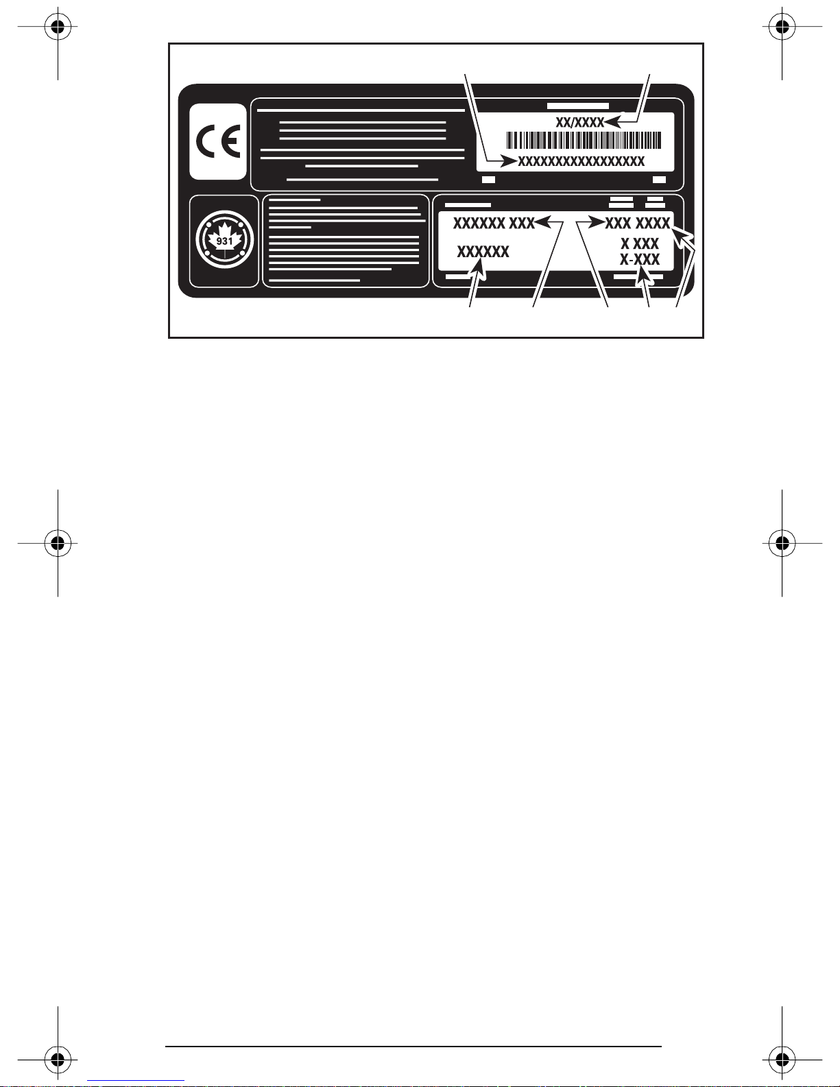
VEHICLE DESCRIPTION DECAL
1. Manufacturing date
2. Vehicle identification number (VIN)
3. Model name
4. Option package
5. Engine type
6. Model year
7. Color codes
4
3576
Serial Numbers
The main components of your snowmobile (engine and frame) are
identified by different serial numbers. It may sometimes become
necessary to locate these numbers for warranty purposes or to trace
your snowmobile in the event of loss. These numbers are required
by the SKI-DOO dealer to complete warranty claims properly. No warranty will be allowed by Bombardier Inc. if the engine serial number
or Vehicle Identification Number (VIN) is removed or mutilated in any
way. We strongly recommend that you take note of all the serial numbers on your snowmobile and supply them to your insurance company.
Vehicle Identification Number (VIN) Location
VIN is scribed on vehicle description decal. See above. It is also embossed on tunnel near vehicle description decal.
17
Page 20

Model Number Location
Model number is part of vehicle identification number (VIN).
X X X X X X X X X X X X X X X X X
Model number
A00A6IA
Engine Serial Number Location
Serial number
A30C01A
TYPICAL
1. Engine serial number
18
1
Page 21

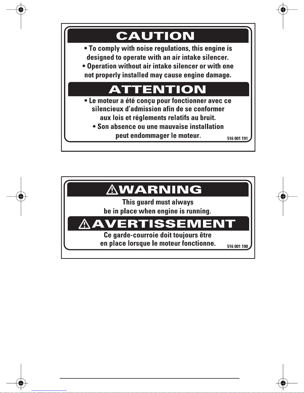
ON-VEHICLE IMPORTANT INSTRUCTIONS
Please read the following instructions carefully before operating snowmobile.
1
A03A04D
TYPICAL — LOCATION OF IMPORTANT INSTRUCTIONS
Instruction 1
2
3
6
4
5
A01A1ZD
SINGLE SEAT MODELS
19
Page 22

Instruction 2
SINGLE SEAT MODELS
A02A0GA
20
Page 23
A01A2EA
ALL MODELS
Instruction 3
A01A2FA
ALL MODELS
Instruction 4
21
Page 24

A01A24D
Instruction 5
TYPICAL — ALL MODELS
SUSPENSION ADJUSTMENT CHART/TABLEAU DES RÉGLAGES DE LA SUSPENSION
FRONT SUSPENSION (SKI)/SUSPENSION AVANT (SKI)
NOT APPLICABLE
SANS OBJET
REAR SUSPENSION/SUSPENSION ARRIÈRE
ADJUST ACCORDING TO LOAD/RÉGLER SELON LA CHARGE
LOAD
CHARGE
Instruction 6
REAR SPRING
RESSORT ARRIÈRE
77
1
2
3
4
1
4
3
6
5
NOT
APPLICABLE
2
SANS OBJET
FOR LOADS EXCEEDING RANGE SHOWN ABOVE, CONSULT YOUR DEALER.
SI LES CHARGES EXCÈDENT LES PLAGES MONTRÉES CI-HAUT, CONSULTEZ VOTRE CONCESSIONNAIRE.
A01A25D
TYPICAL — ALL MODELS
22
Page 25
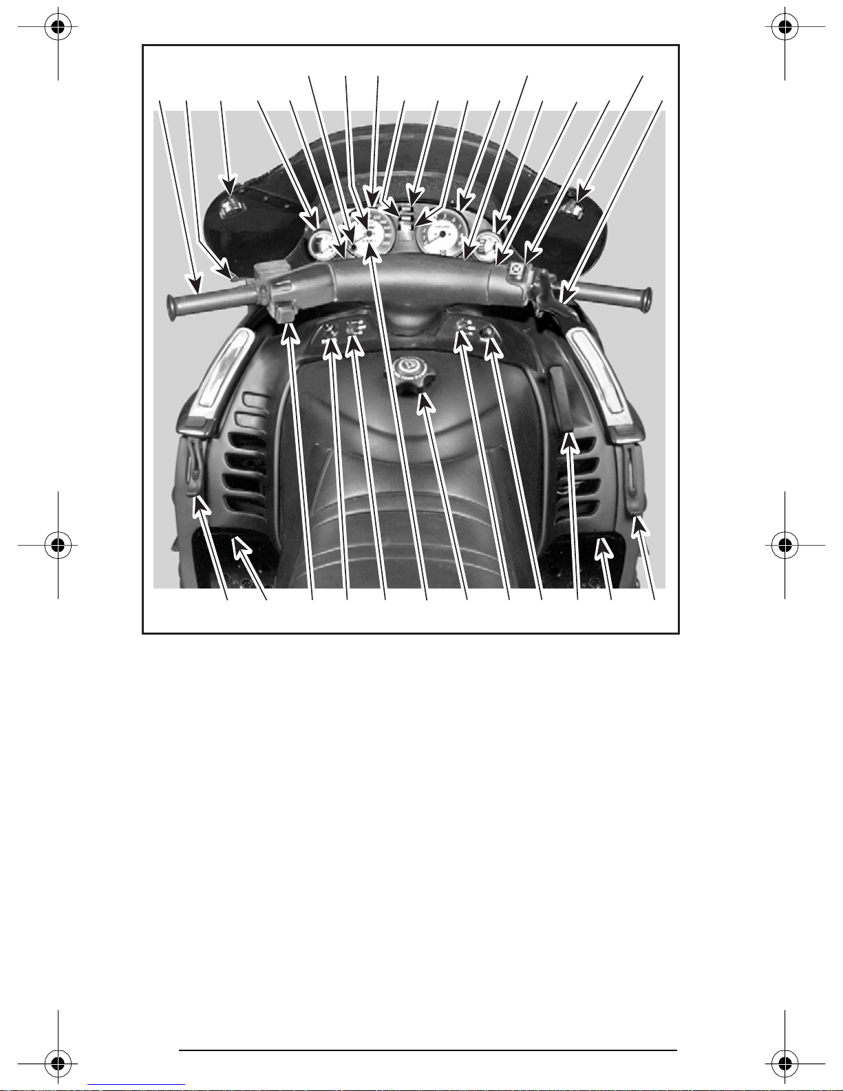
CONTROLS/INSTRUMENTS/EQUIPMENT
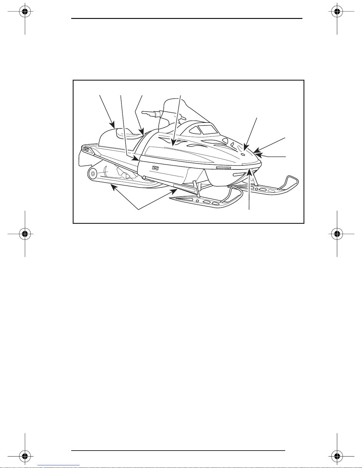
NOTE: Some controls/instruments/equipment do not apply to some
models. In these cases their reference numbers are deliberately
missing in the illustrations. Some controls/instruments/equipment are
optional on some models.
A03A04E
TYPICAL
30
25
34
36
29
28
31
32
35
23
Page 26
17 14
15
26 27
32
19
11
4
18 20
8
1327 5
9
1
A30A0RB
TYPICAL — MACH Z STD/TECH PLUS
24 25 22 21 23 6 25 24712
10
16
24
Page 27

1) Throttle Lever
Located on the right side of handlebar. When compressed, it controls
the engine speed and the engagement of the transmission. When
released, engine speed returns automatically to idle.
WARNING
Throttle lever must operate easily and smoothly. It must return to idle position when released.
2) Brake Lever
Located on the left side of handlebar. When compressed, the brake
is applied. When released, it automatically returns to its original position. Braking effect is proportional to the pressure applied on the
lever and to the type of terrain and its snow coverage.
CAUTION: Excessive or repetitive use of brakes for high speed
stops will cause an overheated brake system. This overheated
condition could cause sudden loss of braking power and/or fire.
3) Parking Brake Button
Located on left side of handlebar. Parking brake should be used
whenever snowmobile is parked.
Whenever parking brake or brake is applied and engine is running,
injection oil level/parking brake pilot lamp lights up to remind you that
it is engaged.
CAUTION: Make sure parking brake is fully disengaged before operating the snowmobile. Otherwise, brake system may overheat
leading to sudden loss of brakes and/or fire.
To engage mechanism, squeeze brake lever and maintain while pull-
ing locking lever with a finger. When brake lever is compressed halfway the brake should be fully applied.
25
Page 28

To release mechanism, squeeze brake lever. Locking lever will automatically return to its original position. Brake lever now returns to rest
position. Always release parking brake before riding.
A30D01A
1. Locking lever
2. OFF
3. ON
1 23
4) Injection Oil Level/Parking Brake Pilot Lamp
(Red)
Lights when injection oil level is low or when parking brake or brake
is applied (with engine running). Check oil level and replenish as soon
as possible. Also lights when parking brake is applied (with engine running).
5) Handlebar
The handlebar controls the direction of travel of the snowmobile. As
the handlebar is rotated to right or left, the skis are turned in the direction of intented travel.
Handlebar height is adjustable. See an authorized SKI-DOO dealer.
26
Page 29

6) Reverse Button
These snowmobiles are capable of a fast reverse. Always remain
seated and apply the brake before shifting. Come to a complete
stop then push reverse button. Ensure the path behind is clear
of obstacles or bystanders. Fast reverse could result in loss of
stability.
Some models are equipped with a Rotax Electronic Reverse (RERTM)
controlled by a reverse button.
General
Driving in reverse is achieved by changing the direction of engine rotation.
Shifting in reverse is an electronic operation consisting of a control
module that modifies the ignition timing of the engine.
When depressing the reverse button, a signal will slow down the engine RPM enough to modify the ignition timing advance. This reverses
crankshaft rotation.
Engine will automatically shift into forward when starting after stopping or stalling.
WARNING
Shifting procedure will take place only when the engine is running.
It is recommended to warm up the engine to its normal operating
temperature before shifting.
Shifting in Reverse
With the snowmobile completely stopped and engine running at idle,
press and release the reverse button.
TM
The DESS
when the snowmobile is engaged in reverse.
Apply throttle slowly and evenly. Allow drive pulley to engage then
accelerate carefully.
Shifting in Forward
With the snowmobile completely stopped and engine running at idle,
press and release the reverse button.
DESS indicator lamp and warning buzzer will stop.
Apply throttle slowly and evenly. Allow drive pulley to engage then
accelerate carefully.
indicator lamp will blink and a warning buzzer will sound
27
Page 30

7) Tether Cut-Out Switch
General
The tether cut-out system shuts-off engine if the driver accidently
falls off the vehicle and the DESS (Digitally Encoded Security Sys-
tem) performs the same function as a key.
Operation
Attach tether cord to clothing then snap tether cord cap over receptacle before starting engine.
A30H09A
TYPICAL
1. Snap over receptacle
2. Attach to eyelet
1 2
28
Page 31
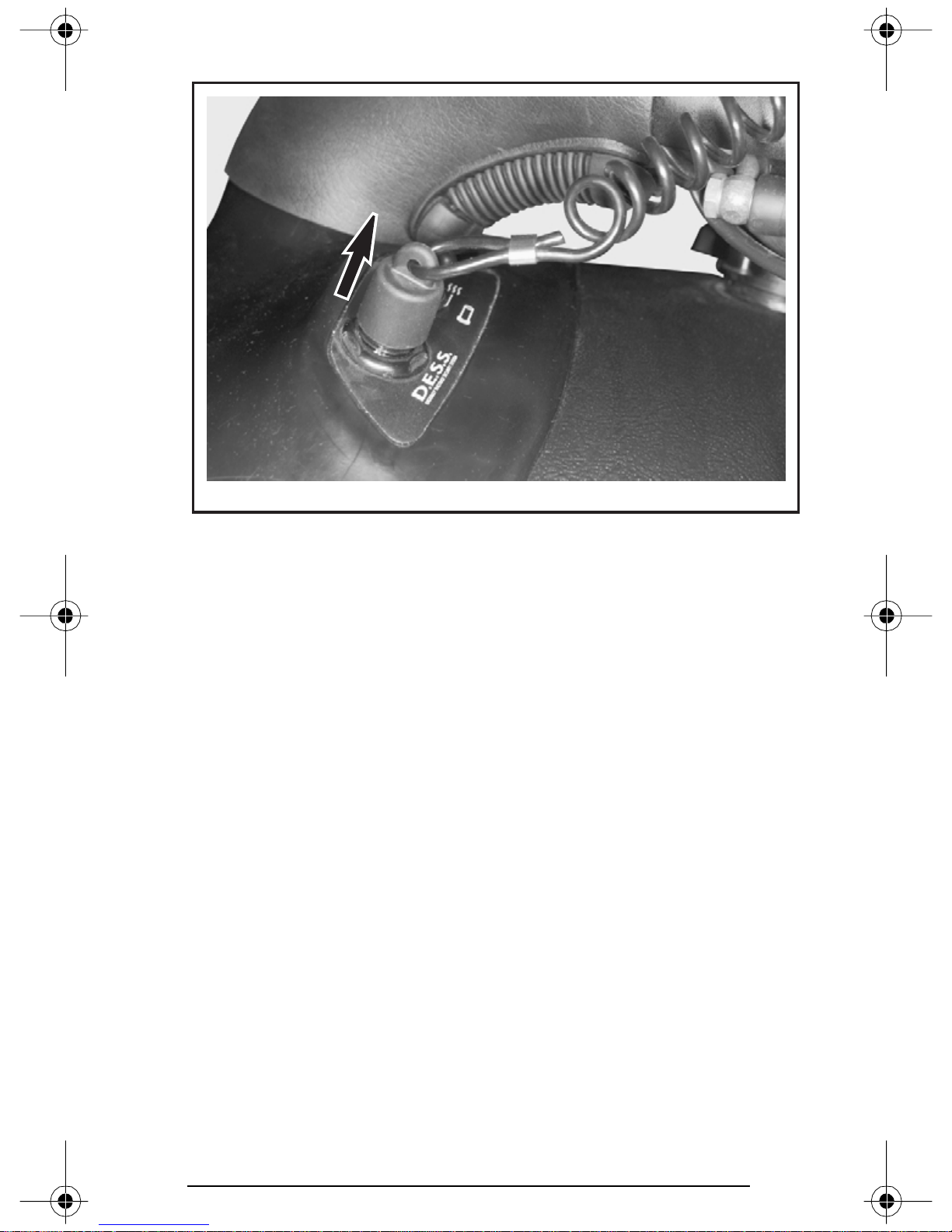
To stop engine, completely pull cap from safety switch.
A30H0AA
TYPICAL
DESS (Digitally Encoded Security System) Description
This system is a deterrent against theft. The tether cord cap provided
with your snowmobile is SKI-DOO dealer programmed and is the only
one that allows engine to turn more than 3000 RPM. If an incorrectly
programmed tether cord cap is installed the engine can not reach
engagement speed required to move vehicle.
Additional Tether Cord Caps
We recommend the purchase of additional tether cord caps from your
authorized SKI-DOO dealer.
Beep and Pilot Lamp Codes
NOTE: Only models with RER have a beeper.
After engine is started 2 beeps and 2 DESS pilot lamp blinks confirm
that the micro-processor has recognized the tether cord cap. The vehicle can be normally driven.
A beep per 3 seconds and DESS pilot lamp blinking as same rate mean
that a bad connection has been detected. Vehicle can not be driven.
29
Page 32
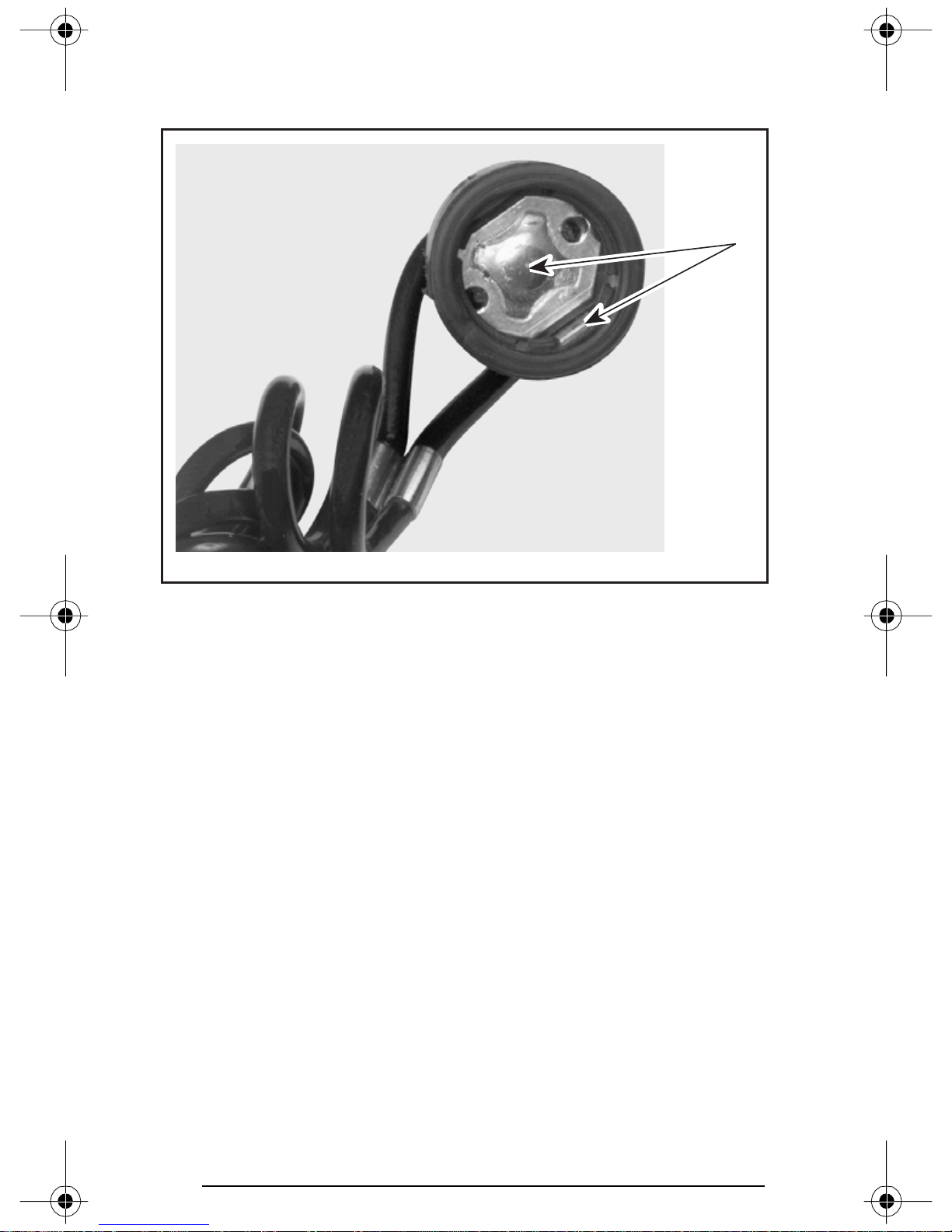
To check for bad connection, remove tether cord cap. Make sure it is
free of dirt or snow. Reinstall tether cord and restart engine. If a beep
per 3 seconds still occurs contact an authorized SKI-DOO dealer.
1
A30H08A
1. Free of dirt or snow
A rapid beeping and DESS pilot lamp blinking at same rate mean that
an incorrectly programmed tether cord is being used. Vehicle can not
be driven.
8) DESS Pilot Lamp
This lamp will light up to confirm DESS status. Refer to previous paragraphs for description.
30
Page 33
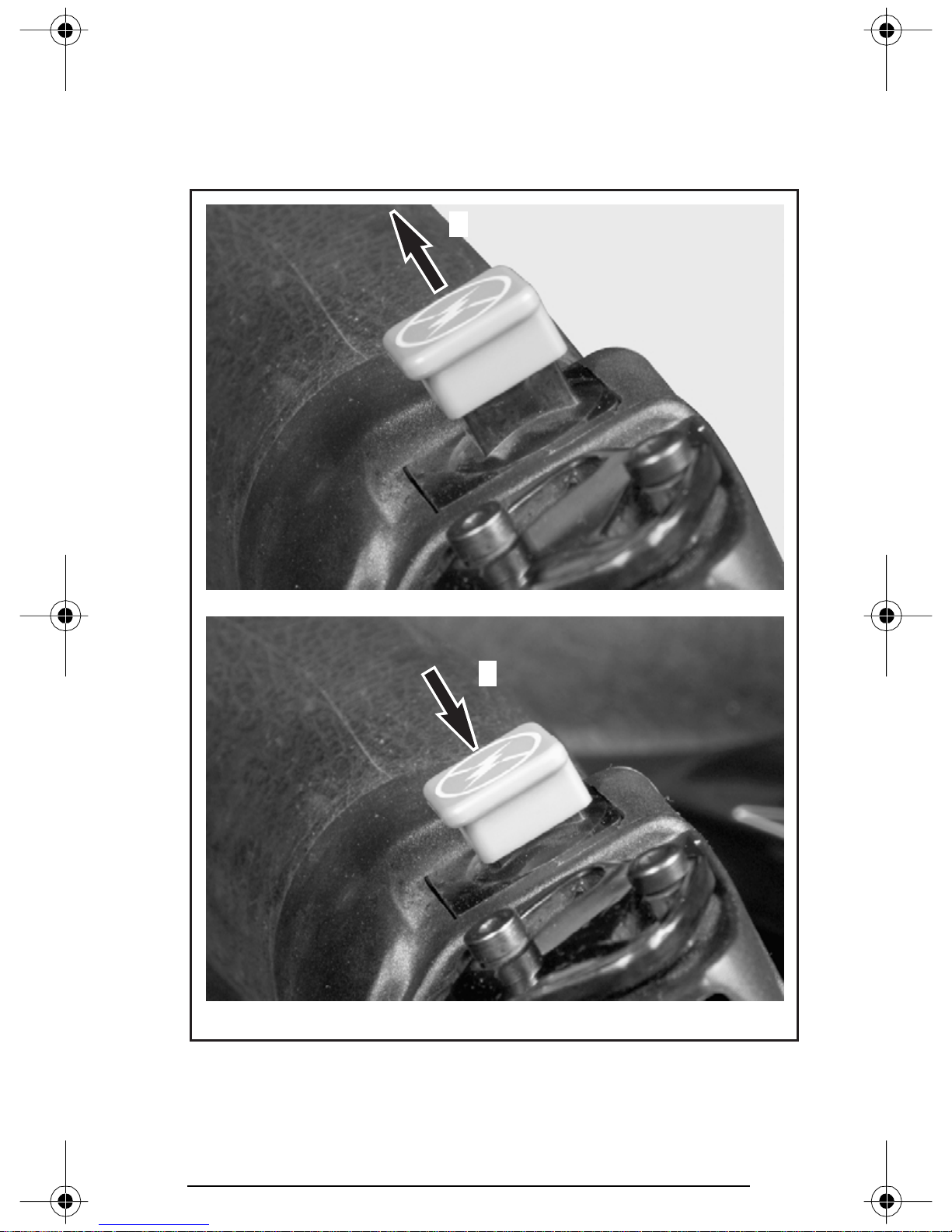
9) Engine Cut-Out Switch
A push-pull type switch located on the right side of the handlebar. To
stop the engine, push the button to the lower OFF position and simultaneously apply the brake. To restart, button must be at the upper
ON position.
1
A30E03A
TYPICAL
1. ON
2. OFF
2
31
Page 34
All drivers of the snowmobile should familiarize themselves with the
function of this device by using it several times on first outing and to
stop the engine there after. Thereby being mentally prepared for
emergency situations requiring its use.
WARNING
If the switch has been used in a mechanical malfunction, the
source of malfunction should be determined and corrected
before restarting engine.
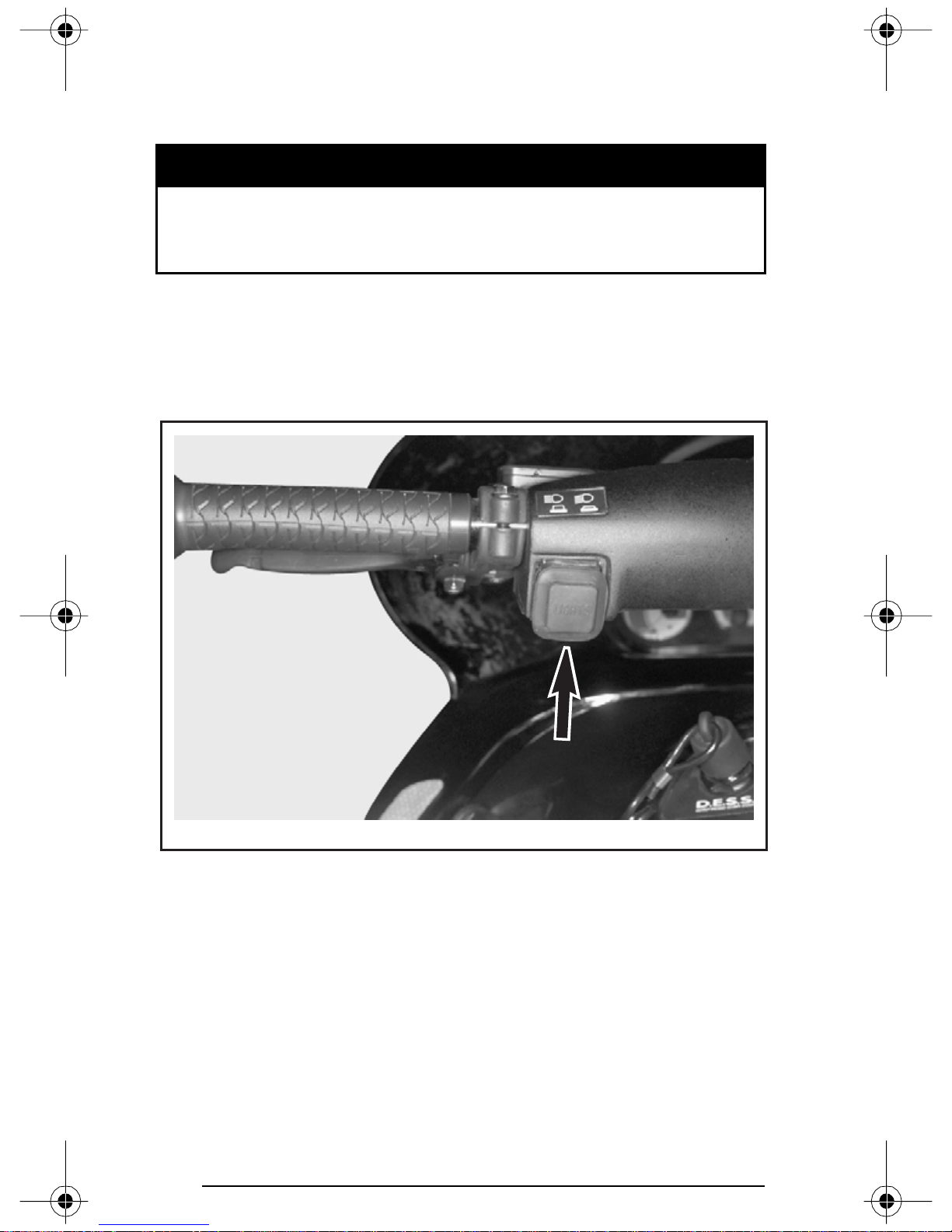
10) Headlamp Dimmer Switch
Located on left side of handlebar, allows selection of headlamp beam
Note that lights are automatically ON whenever the engine is running.
A30H0BA
11) High Beam Pilot Lamp (Blue)
Lights when headlamp is on HIGH beam.
12) Rewind Starter Handle
Auto-rewind type located on right hand side of snowmobile. To engage mechanism, pull handle slowly until a resistance is felt then pull
vigorously. Slowly release handle.
32
Page 35
13) Choke Lever
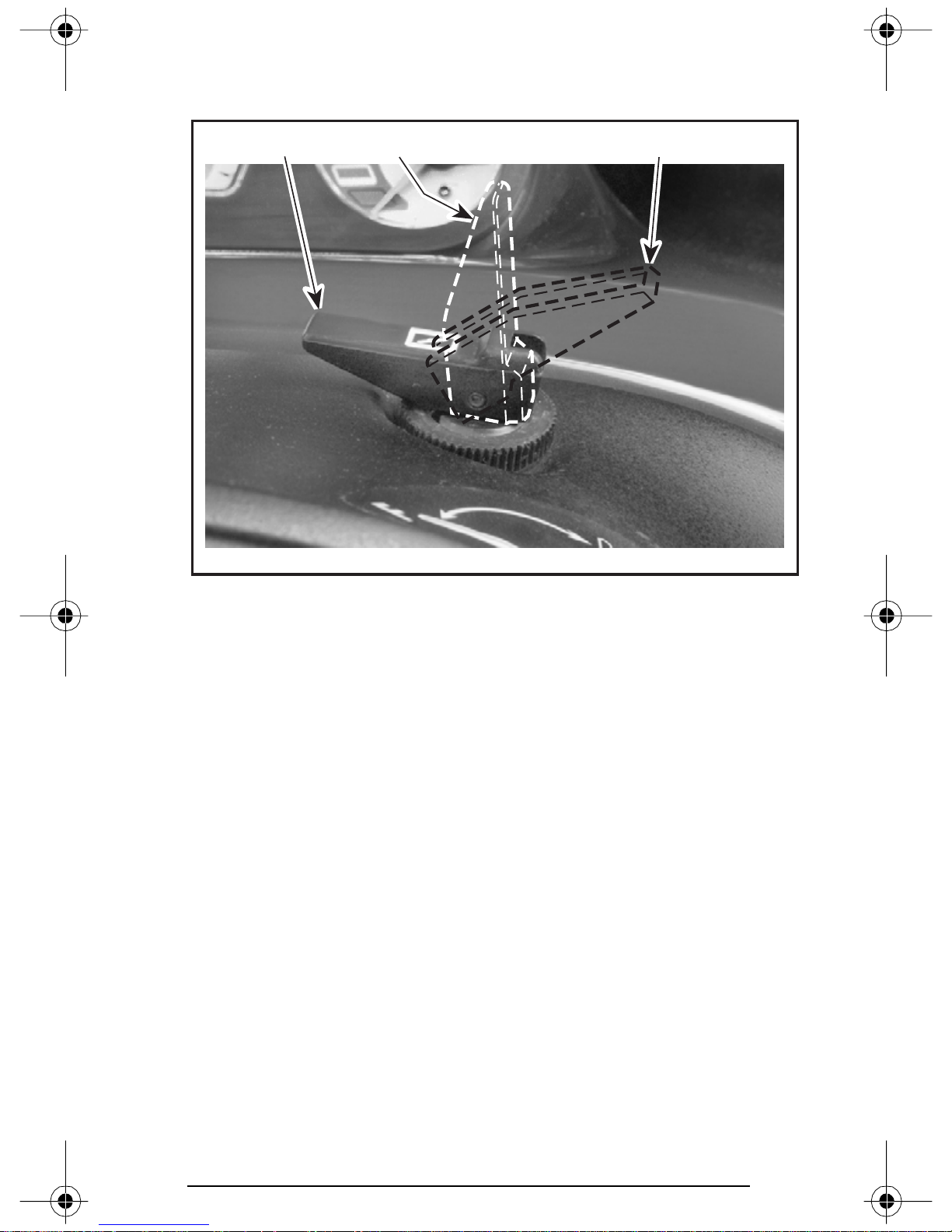
This device features a 3-position lever to facilitate cold start.
0 12
A30H0DA
0. OFF
1. Position 1
2. Position 2
Refer to OPERATING INSTRUCTIONS for more details.
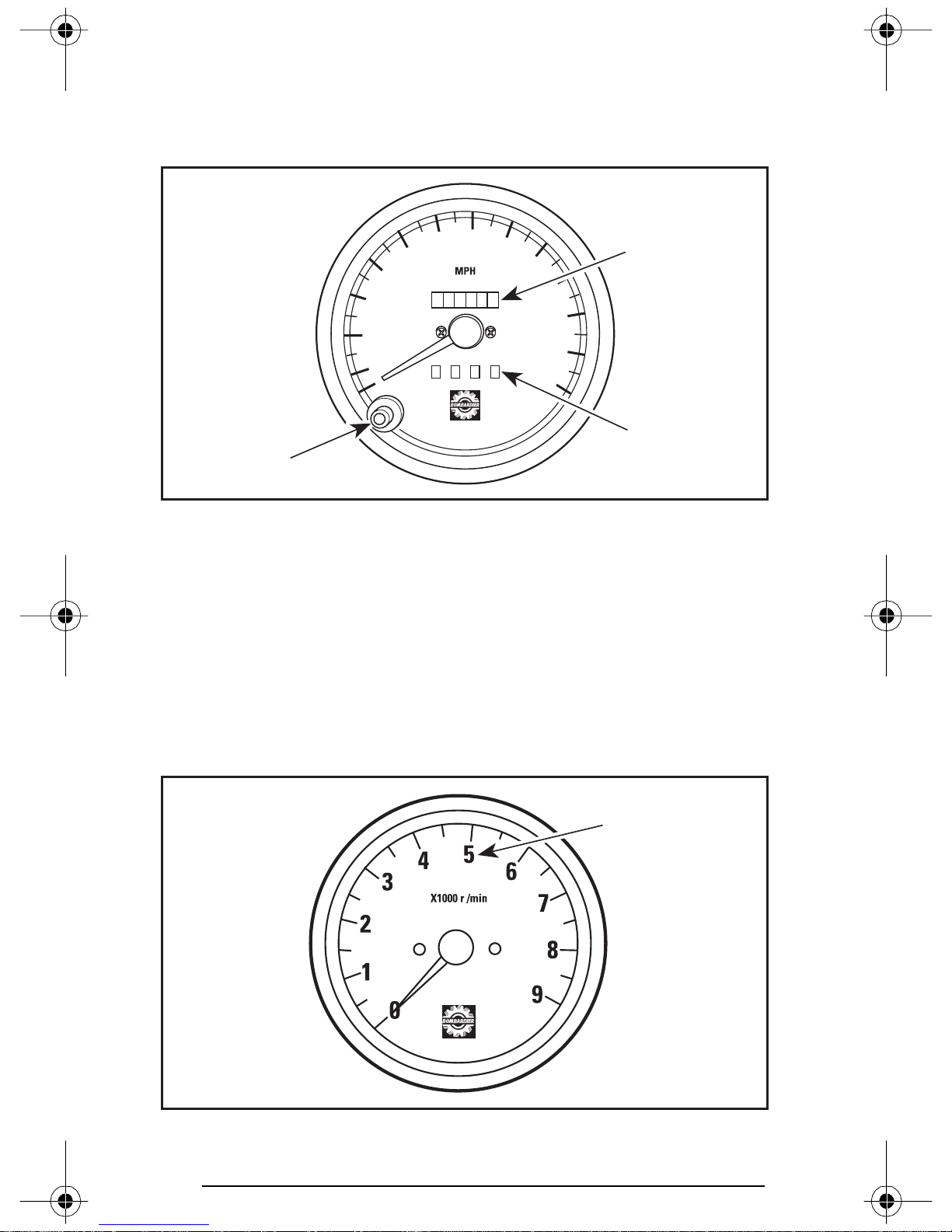
14) Speedometer
These vehicles are equipped with a speedometer graduated in kilometer per hour (miles per hour for the USA).
Direct-reading dial indicates the speed of the snowmobile in kilometers per hour (miles per hour for the USA).
15) Odometer
Odometer records the total distance travelled in kilometers (miles for
the USA).
33
Page 36
16) Trip Meter
Records distance travelled in kilometers (miles for the USA) until it is
reset. It can be used to establish a fuel tank range or distance between 2 relays for instance.
70
30
60
50
40
000000
80
90
1
100
110
20
120
10
0
0 0 0 0
130
2
3
A06H1FA
1. Odometer
2. Trip meter
3. Reset button
17) Trip Meter Reset Button
To reset, push on button until all numbers read zero.
18) Tachometer
Direct-reading dial indicates the number of thousand of revolutions
per minute (RPM) of the engine.
1
A06H05A
1. Multiply the reading by 1000
34
Page 37
19) Temperature Gauge
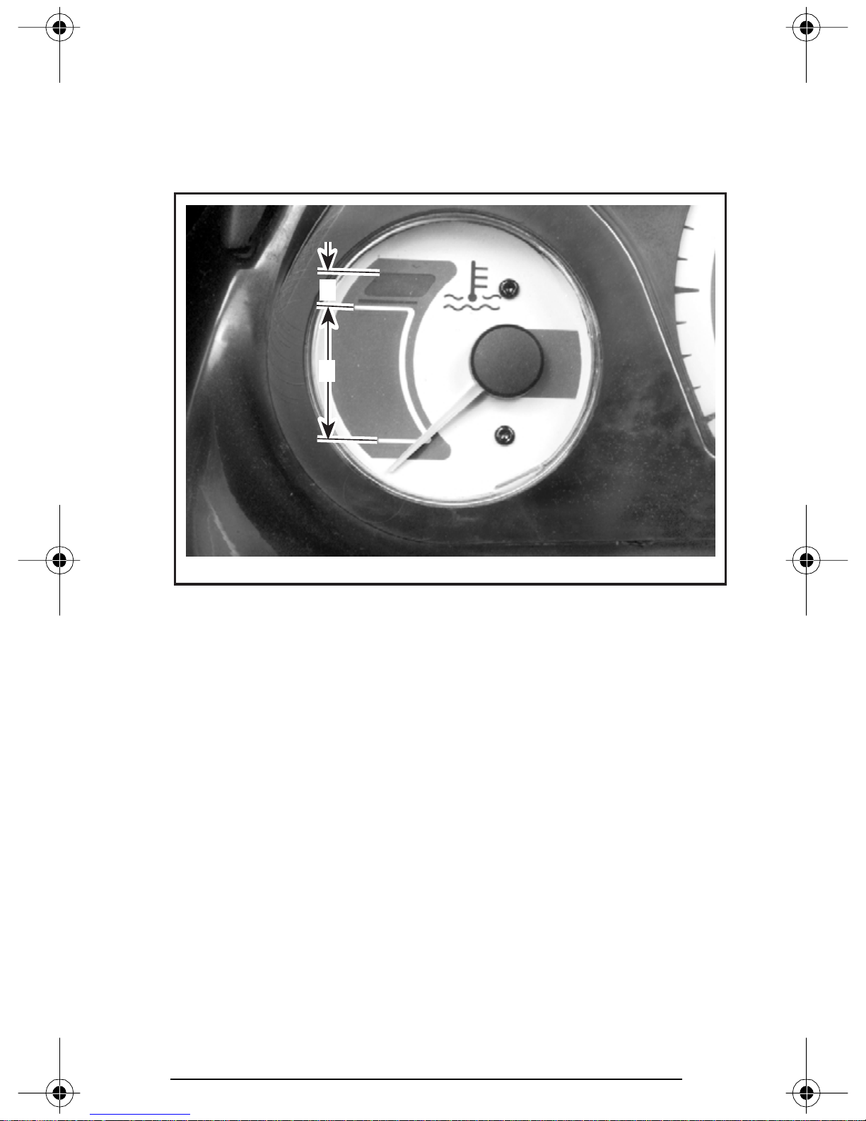
The gauge indicates engine coolant temperature. The needle moves
to the normal range as engine warms. Under all riding conditions, the
needle should stay within this range. If needle moves into the overheat range, reduce snowmobile speed and run snowmobile in loose
snow or stop engine immediately.
2
1
A30H0GA
1. Normal
2. Overheat
35
Page 38
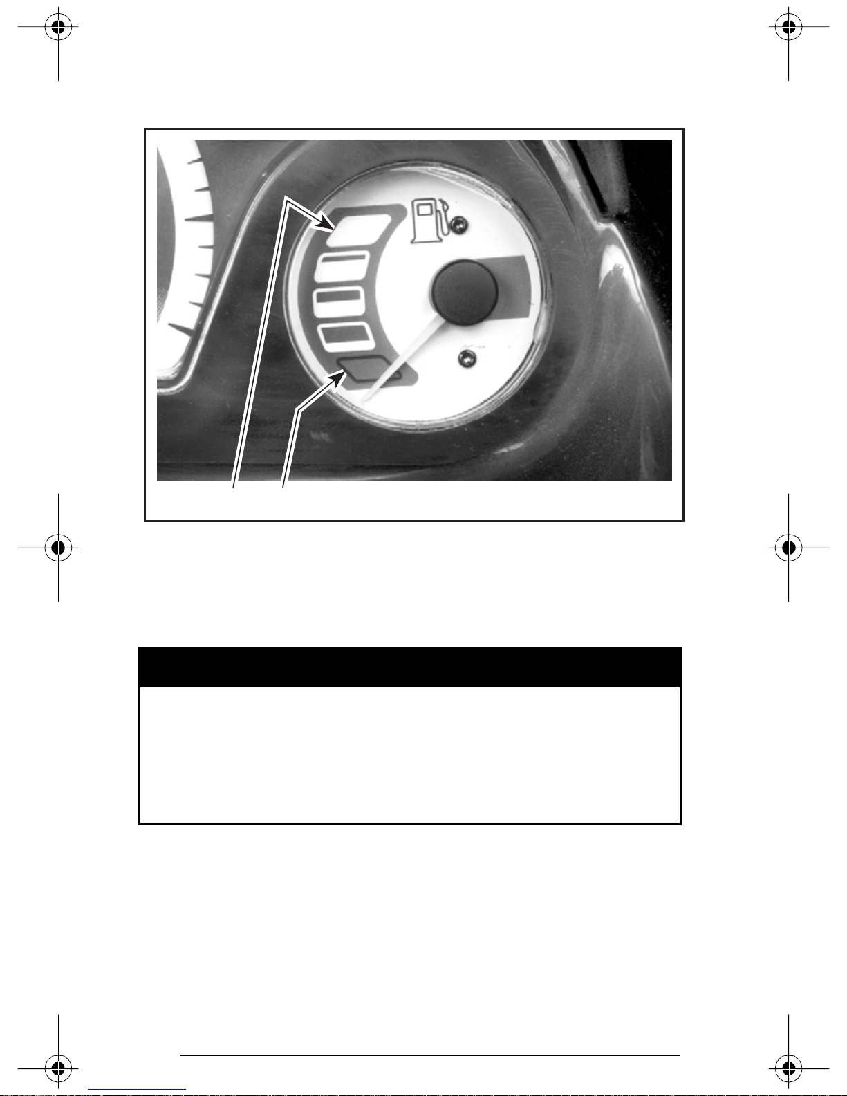
20) Electric Fuel Level Gauge
Dash-mounted gauge to facilitate fuel level reading. This gauge functions when engine is running.
A30H0HA
1. Full
2. Empty
1
2
21) Fuel Tank Cap
Unscrew to fill up tank then fully tighten.
Fuel may be pressurized, open cap slowly. Fuel is flammable
and explosive. Never use an open flame to check fuel level.
Never smoke or allow flame or spark in vicinity. Never top up
the fuel tank before placing the vehicle in a warm area. As temperature increases, fuel expands and may overflow. Always
wipe off any fuel spillage from the vehicle.
CAUTION: Do not mismatch oil reservoir cap with fuel tank cap.
Install cap that is identified OCTANE RATING OF 91 RECOMMENDED.
WARNING
36
Page 39
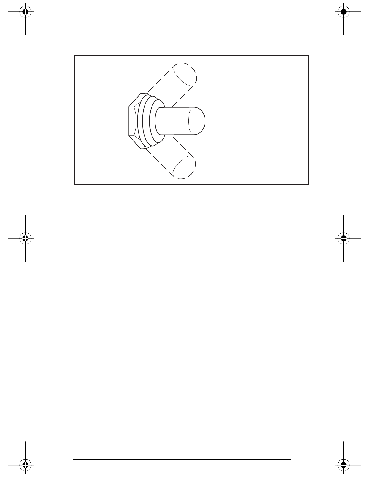
22) Heated Grip Switch
Three-position toggle switch. Select the desired position to keep your
hands at a comfortable temperature.
1
2
3
A25H05A
TYPICAL
1. HOT
2. OFF
3. WARM
23) Heated Throttle Lever Switch
Three-position toggle switch. Select the desired position to keep your
right thumb at a comfortable temperature. See illustration above.
24) Hood Latches
Stretch and unhook the latches to unlock the hood from its anchors.
Always lift hood gently until stopped by retaining device.
Close hood slowly then hook up latches.
37
Page 40
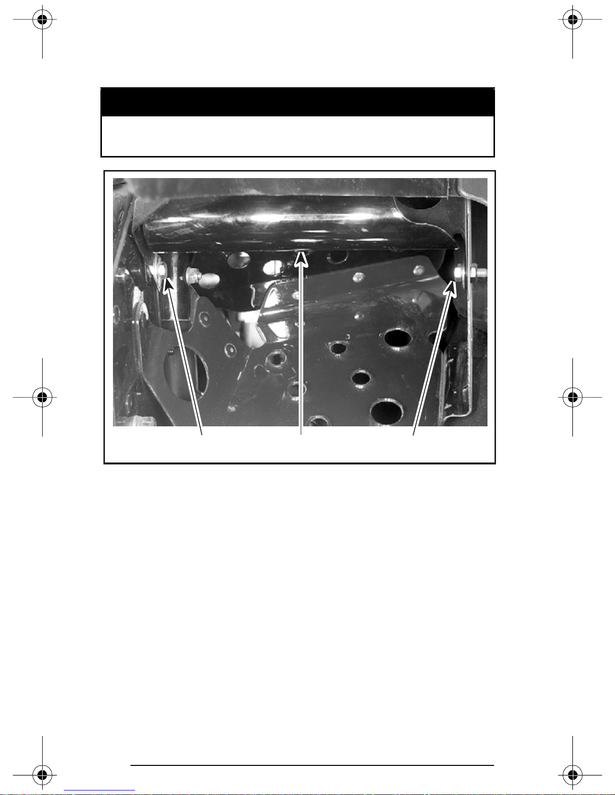
25) Adjustable Toeholds
Each toehold can be adjusted to suit driver’s preference. Loosen bolts,
adjust then, retighten bolts to 10 N•m (89 lbf•in).
Adjust with vehicle at rest in a safe place. Securely tighten all
adjustments. Do not adjust too snugly.
WARNING
A30H0MA
RIGHT SIDE SHOWN
1. Toehold
2. After adjustment retighten bolts to 10 N•m (89 lbf•in)
1 22
38
Page 41
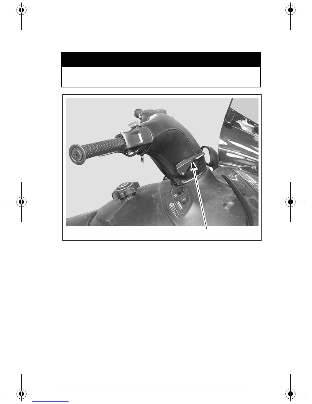
26) Adjustable Handlebar
Handlebar angle can be adjusted to suit driver’s preference. Lift lever,
tilt handlebar to desired position then release lever. Lever will locked
on each position.
Adjust with vehicle at rest in a safe place. Securely tighten all
adjustments.
WARNING
A30G16A
1. Lever
1
39
Page 42
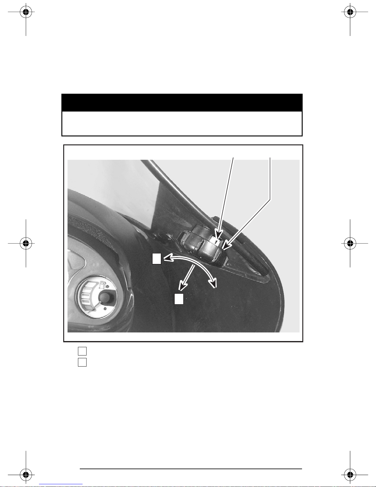
27) Adjustable Windshield
Windshield height can be adjusted to suit driver’s preference. Posi-
tion 1 corresponds to lower windshield height. Position 10 corresponds to higher windshield height.
Knobs are locked on each position. To unlock first pull knobs then,
turn to adjust windshield height. Both knobs must be set to same
position.
Adjust with vehicle at rest in a safe place. Securely tighten all
adjustments.
WARNING
12
2
1
A30H2BB
1
Step : Pull knob by about 3 mm (1/8 in)
2
Step : Turn to desired position, then release
1. Knob
2. Position number
40
Page 43
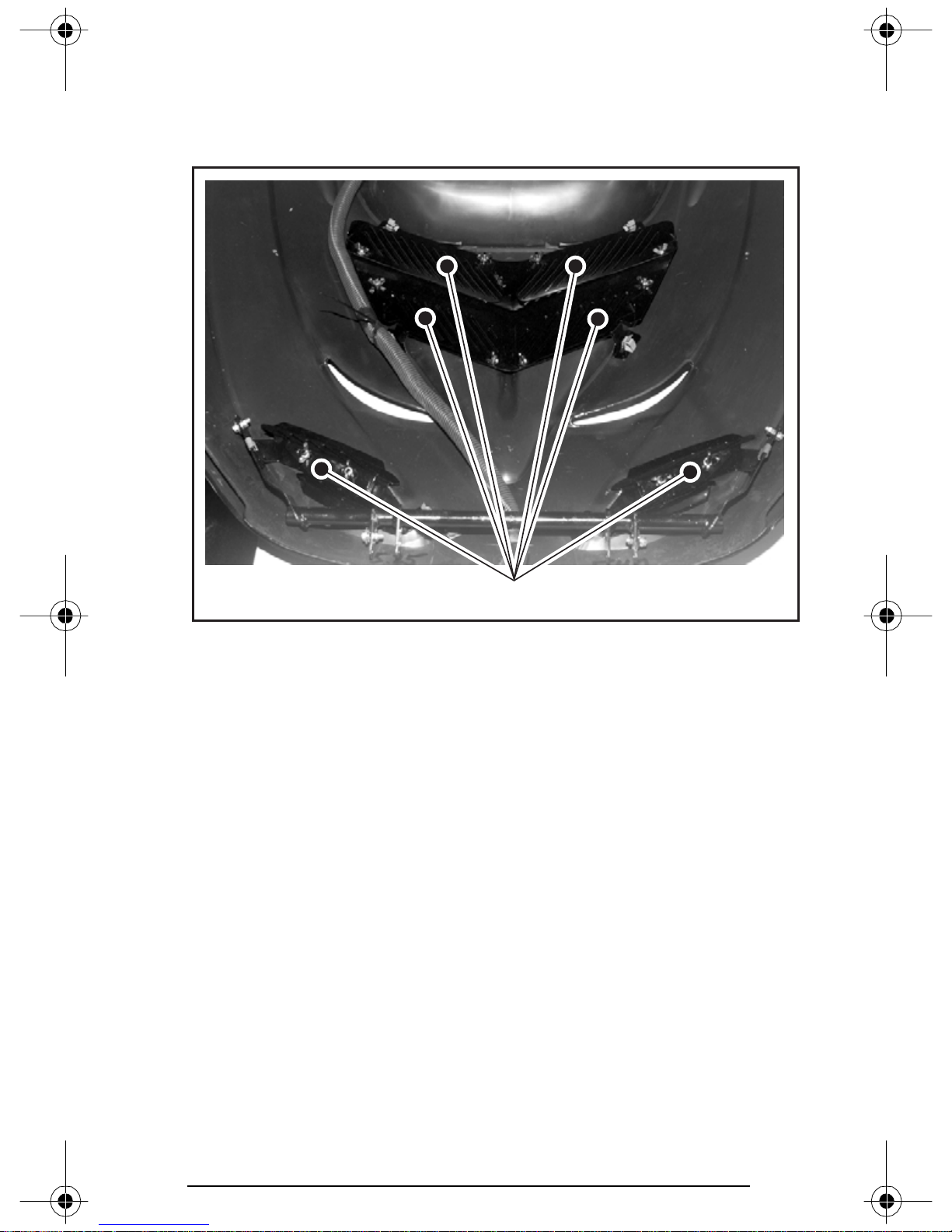
28) Hood Grills
These hood grills must be closed at all times except when riding at
high speeds and/or when outside temperature is above 5°C (40°F).
Slightly unscrew wing nuts, slide close grills then, retighten wing nuts.
A30H0TA
1. Grills
1
41
Page 44
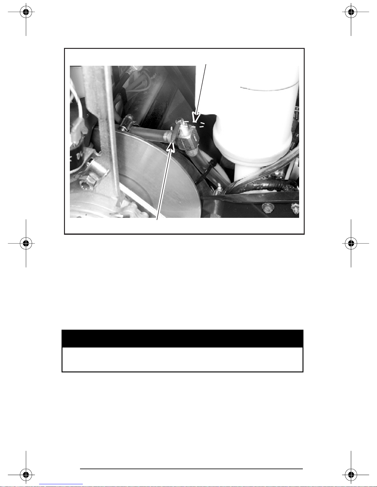
29) Fuel Shut-Off Valve
Valve should be closed when transporting or storing snowmobile.
1
A30I01A
1. Opened
2. Closed
Fully open the valve in order to operate the snowmobile.
CAUTION: Always fully open the valve before riding. Never allow
the valve to remain half opened.
2
30) Storage Compartment
A storage compartment is provided inside rear portion of seat.
All storage compartments must be properly latched and they
must not contain any heavy or breakable objects.
WARNING
42
Page 45
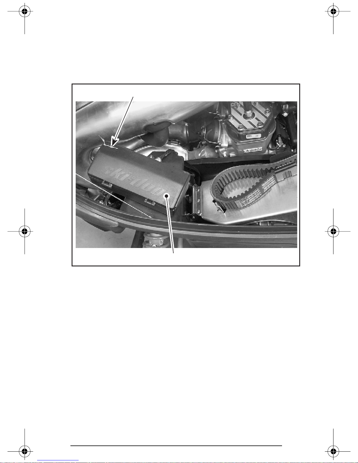
31) Tool Box
A tool box containing tools for basic maintenance is supplied with the
vehicle. Tool box is located in engine compartment in front of belt
guard.
NOTE: The plastic bag containing tools may be discarded to ease storing tools.
2
A30D0PA
1. Tool box
2. Remove hair pin before opening
1
32) Spark Plug Holder
To keep spare spark plugs dry and prevent shocks that might affect
the adjustment or break them, a compartment is provided in tool box.
NOTE: Always adjust spark plug gap according to SPECIFICATIONS
before installation.
NOTE: Spare spark plugs are not supplied with the snowmobile.
43
Page 46
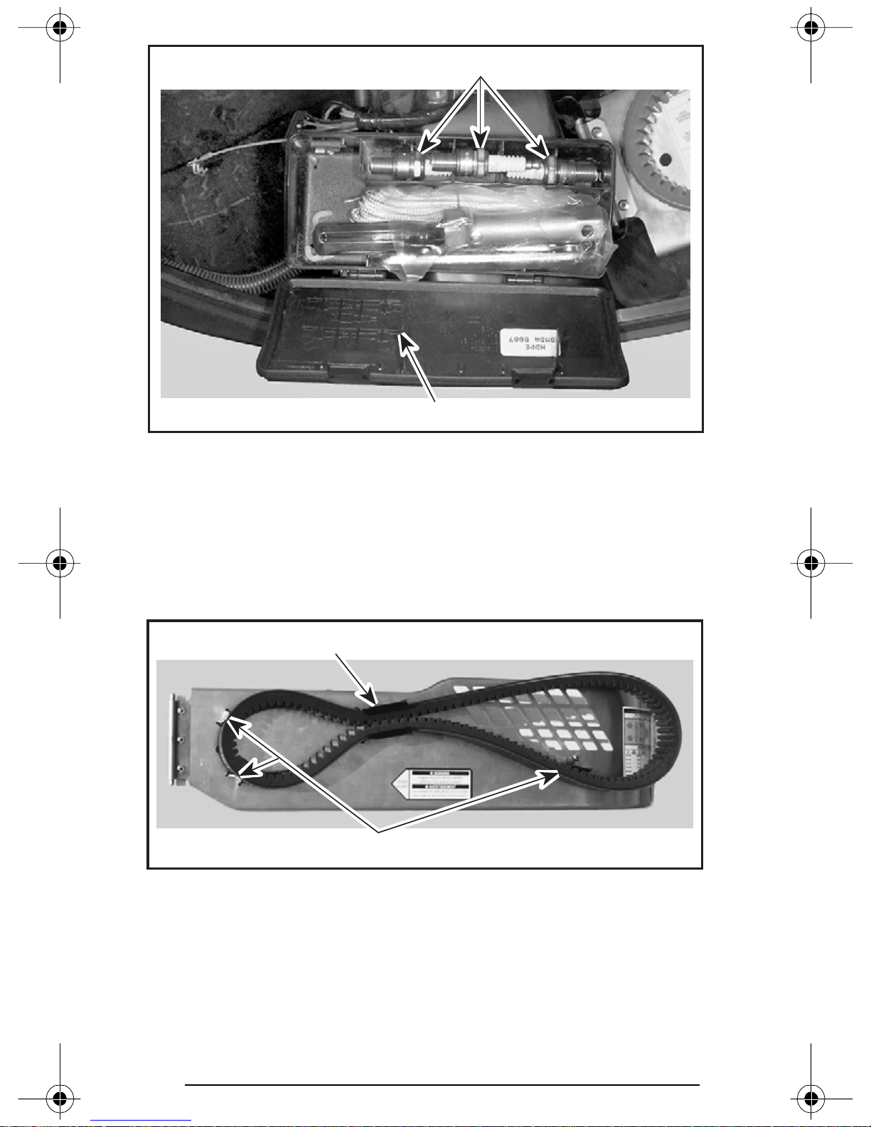
1
A30D04A
1. Spare spark plugs stored in tool box
2. Instructions for spare spark plugs removal
2
33) Spare Drive Belt Holder
A spare drive belt can be installed in drive belt holder clip. Make sure
to position spare drive belt as illustrated.
NOTE: Spare drive belt is not supplied with the snowmobile.
1
A30D0QA
1. Spare drive belt installed in holder clip
2. Spare drive belt on this side of stopper
44
2
Page 47
34) Fuse
CAUTION: Do not use a higher rated fuse as this can cause se-
vere damage to electric components and/or fire.
If fuse has burnt out source of malfunction should be determined and corrected before restarting. See an authorized
SKI-DOO dealer for servicing.
Electric Fuel Level Gauge Fuse
See an authorized SKI-DOO dealer for fuse replacement.
WARNING
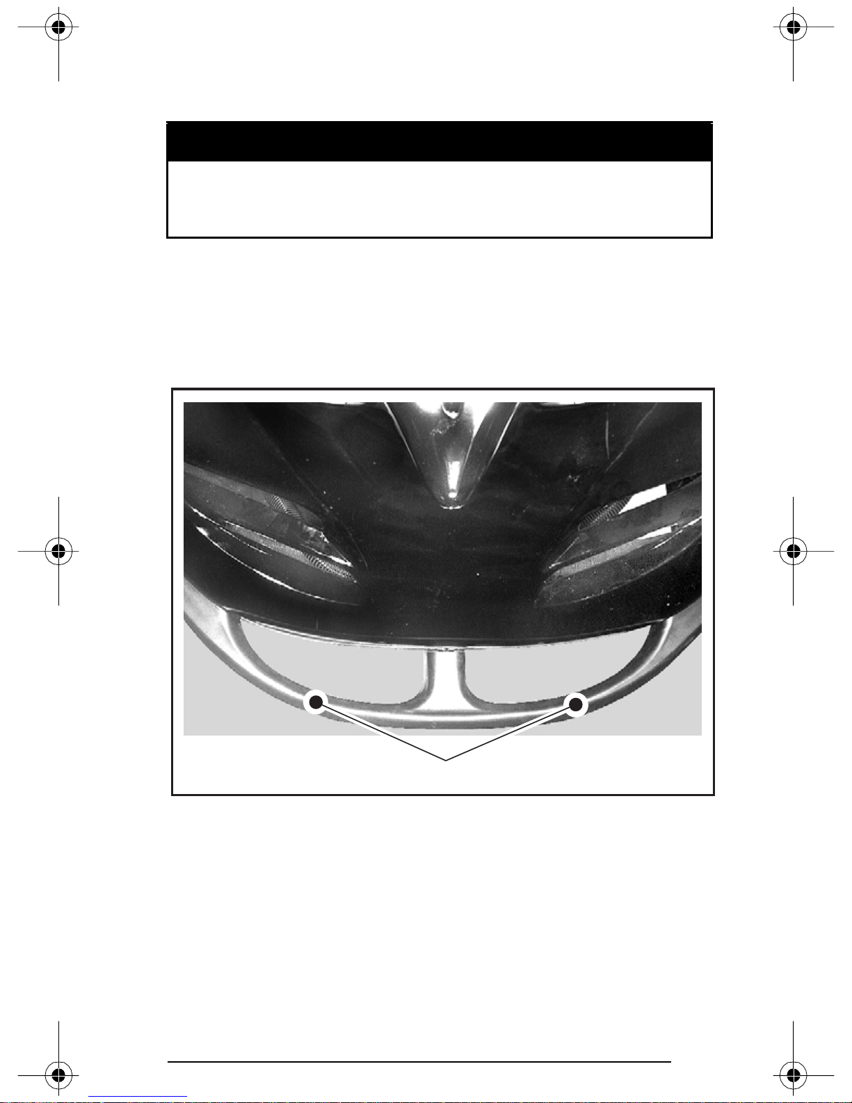
35) Front Grab Handles/Front Bumper
To be used whenever front of snowmobile requires manual lifting.
A30H0NA
1. Front grab handles
CAUTION: Do not use skis to pull or lift snowmobile.
1
45
Page 48
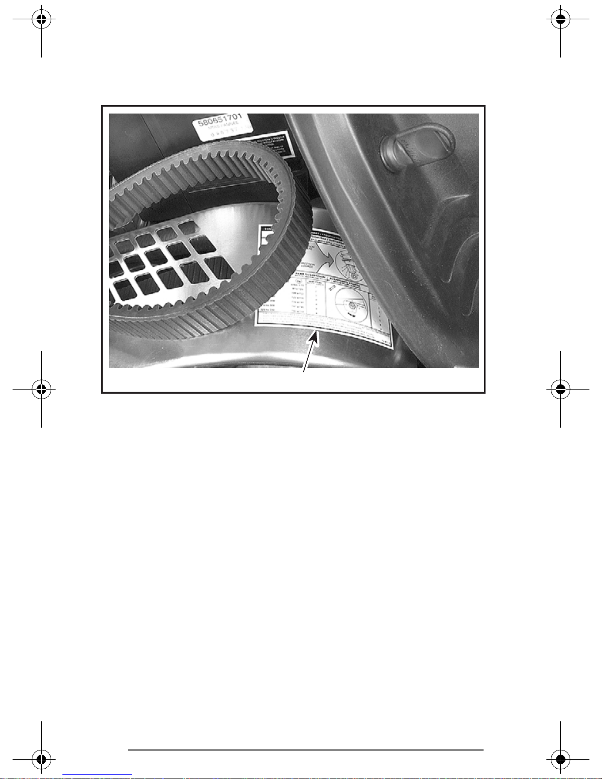
36) Adjustable Suspensions
For factory recommended adjustments refer to decal on belt guard.
It describes settings for optimum comfort according to load for your
SKI-DOO model.
A30F07A
TYPICAL
1. Decal
1
46
Page 49
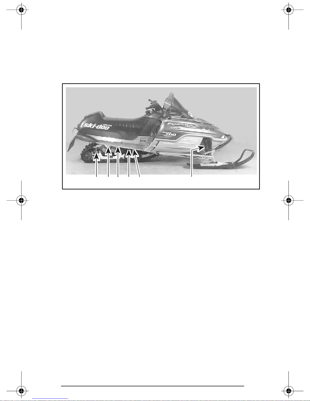
General
Snowmobile handling and comfort depend upon suspension adjustments.
Choice of suspension adjustments vary with carrying load, driver’s
weight, personal preference, riding speed and field condition.
NOTE: Some adjustments may not apply to your snowmobile. Use
special keys in tool box.
A32F0FA
TYPICAL
1. Rear springs for comfort and ride height
2. Center spring for steering behavior
3. Coupling blocks — Handling
4. Stopper strap for snowmobile weight transfer
5. Front springs for handling
6. Rear shock motion ratio — Damping strength
4 1 2 3 5
6
47
Page 50
Guidelines to Adjust Suspension
The best way to set up suspension, is to start from factory settings
then customize each adjustment one at a time. Adjustments 2 through
6 are interrelated. It may be necessary to readjust center spring after
adjusting front springs for instance. Test run the snowmobile under the
same conditions; trail, speed, snow, driver riding position, etc. Change
one adjustment and retest. Proceed methodically until you are satisfied.
WARNING
Always completely stop vehicle and engine before attempting
any suspension adjustments.
CAUTION: Whenever adjusting rear suspension, check track tension and adjust as necessary.
Slight suspension bottoming occurring under the worst riding conditions indicates a good choice of spring preload.
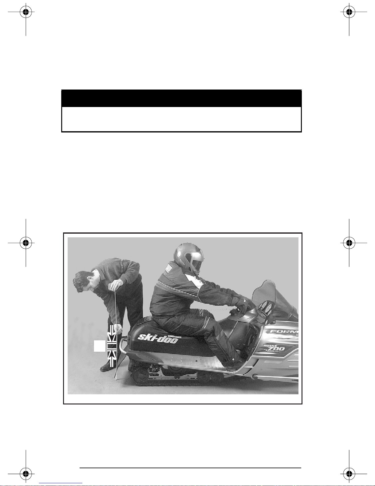
1. Rear Springs — Comfort and Ride Height
Grasp rear bumper and lift until suspension is fully extended. From
this point, rear of snowmobile should collapse by 50 to 75 mm (2 to
3 in) when driver and passenger (if so applicable) take place.
A
A32F0BA
TYP ICA L — PROPER ADJUSTMENT
A. 50 to 75 mm (2 to 3 in)
48
Page 51
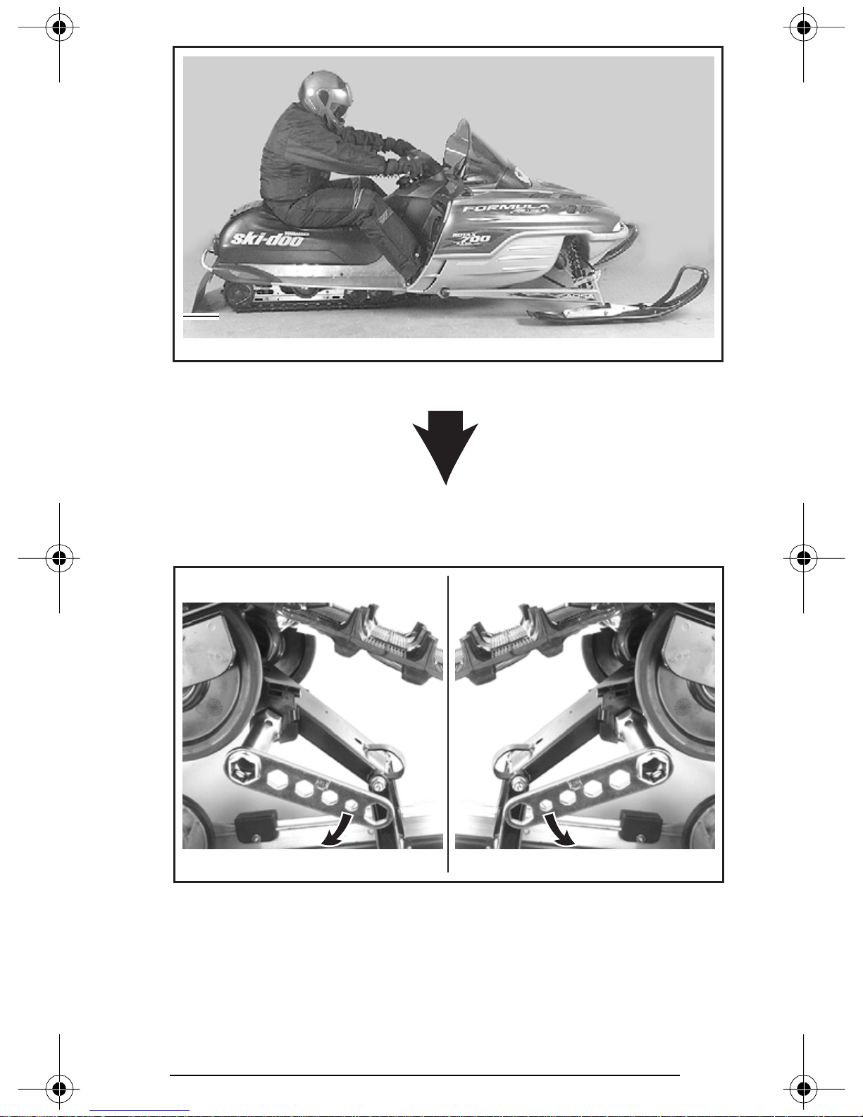
A32F0CA
TYP ICA L — TOO SOFT OF ADJUSTMENT
Turn the left side adjustment cam in a clockwise direction, the right side
cam in a counterclockwise direction. Left and right adjustment cams may
be set at different position.
RHLH
A30F04A
TYP ICA L
1. Increase spring preload
1 1
49
Page 52
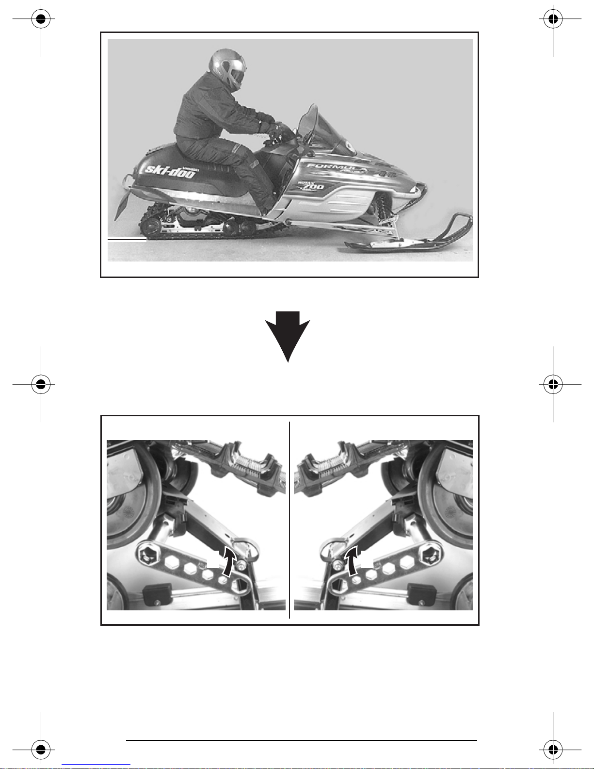
A32F0DA
TYP ICA L — TOO HARD OF ADJUSTMENT
Turn the left side adjustment cam in a counterclockwise direction, the
right side cam in a clockwise direction. Left and right adjustment cams
may be at different position.
RHLH
A30F04B
TYP ICA L
1. Decrease spring preload
50
1 1
Page 53
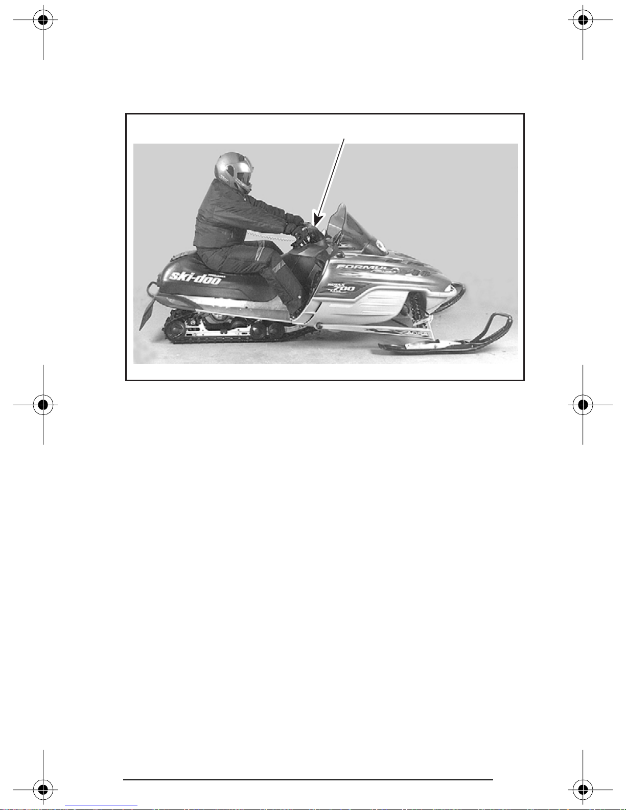
2. Center Spring — Steering Behavior
Ride at moderate speed on a trail.
If steering is too easy or too hard to turn, adjust center spring accord-
ingly.
1
A32F0EA
TYP ICA L — GOOD ADJUSTMENT AT MODERATE SPEED
1. Steering easy to turn
51
Page 54
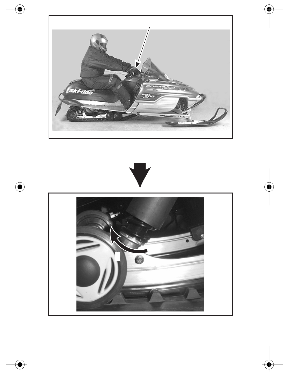
A32F0EA
TYP ICA L — TOO SOFT OF ADJUSTMENT
1. Steering hard to turn
1
A32F01A
TYP ICA L
1. Use adjuster wrench provided in tool box to increase preload
52
1
Page 55
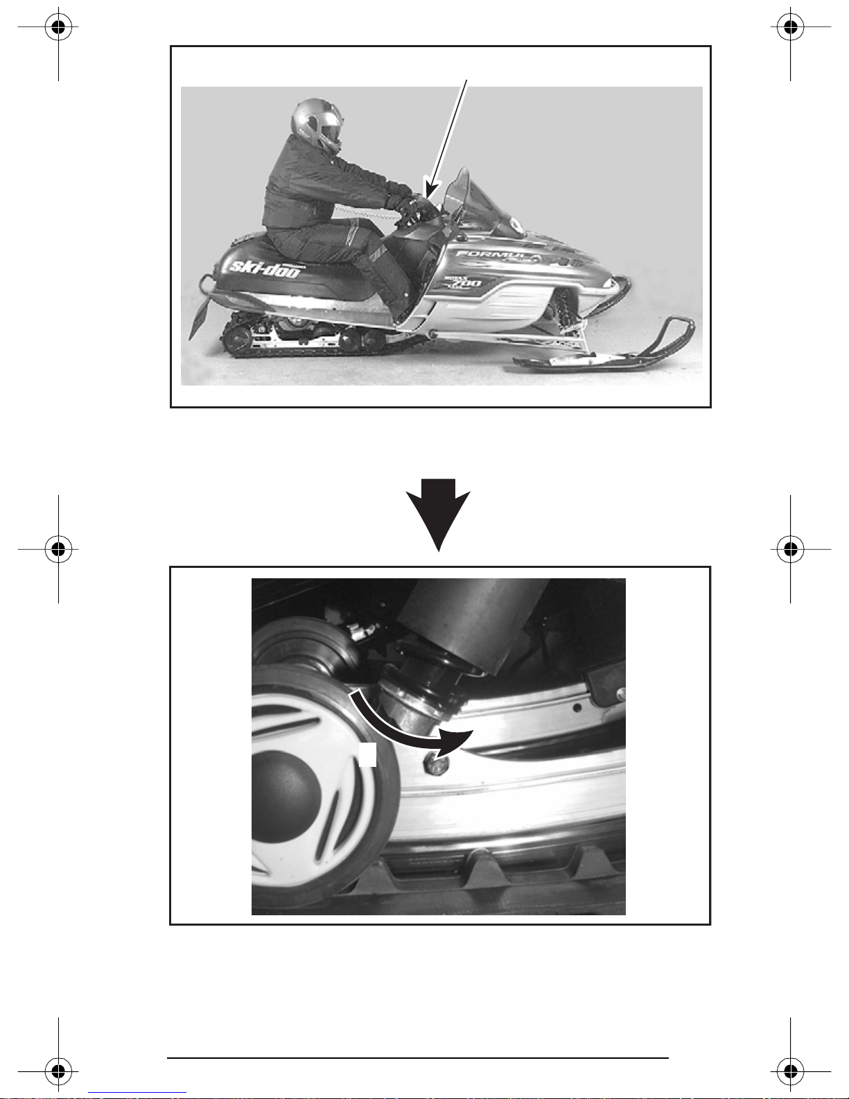
A32F0EA
TYP ICA L — TOO HARD OF ADJUSTMENT
1. Steering less aggressive
1
A32F01B
TYP ICA L
1. Use adjuster wrench provided in tool box to decrease preload
1
53
Page 56
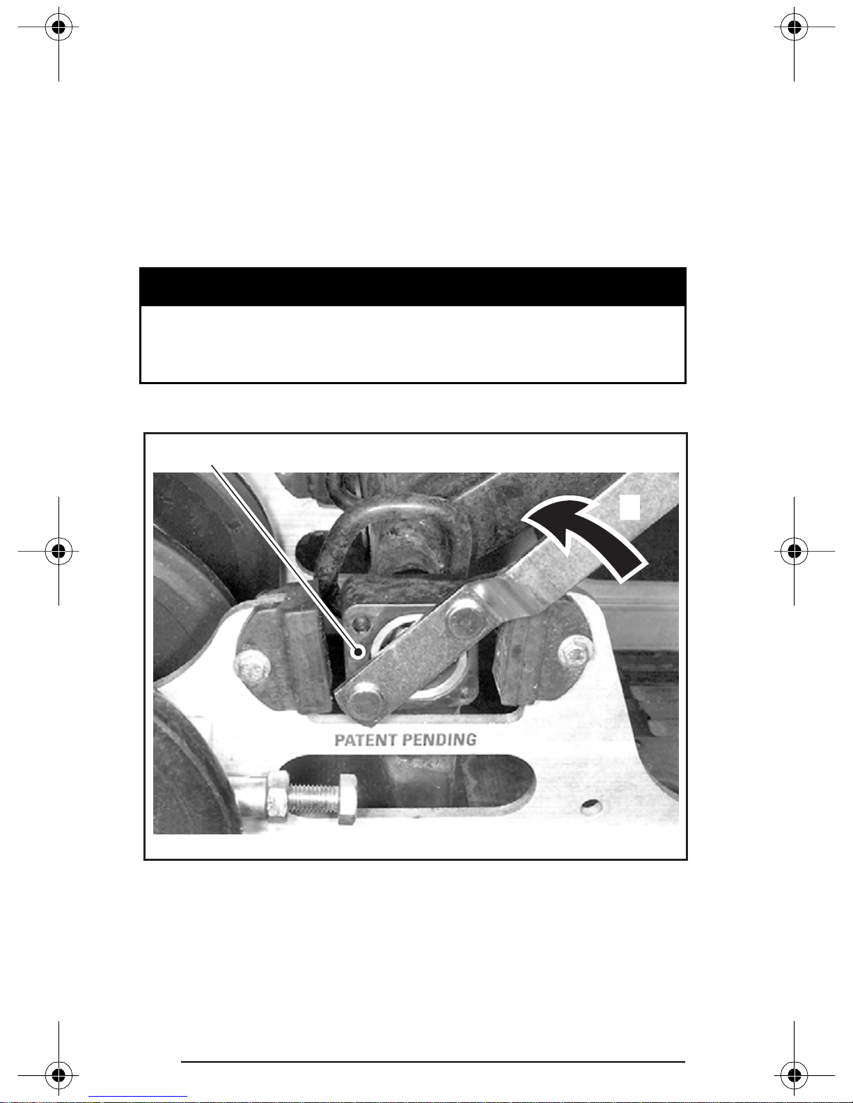
3. Coupling Blocks — Handling
Ride at moderate speed and check for desired handling.
When driver and passenger (if applicable) take place the coupling
blocks should be centered between rubber stoppers.This condition
is achieved when a proper rear spring preload is done. See above rear
spring adjustment.
If handling requires adjustment, turn both left and right blocks by 90°.
There are only two adjustment positions. Thicker part of block must
be facing rearward or downward.
WARNING
Both blocks must be set at the same position. Otherwise vehicle behavior may be unpredicted and suspension may become warped.
Use tool provided in tool box to adjust coupling blocks.
A32F0IA
1
2
COUPLING BLOCK — RIGHT SIDE VIEW (“R” — RIGHT EMBOSSED ON BLOCK)
1. Thicker part of block facing rearward (fully coupled suspension) — less track grip
and more skis steering
2. Turn block in this direction to adjust to the other position
54
Page 57
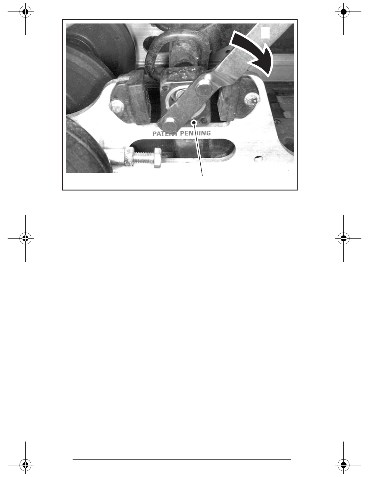
2
A32F0JA
COUPLING BLOCK — RIGHT SIDE VIEW
(“R” — RIGHT EMBOSSED ON BLOCK)
1. Thicker part of block facing downward (partly coupled suspension) — more track
grip and less skis steering
2. Turn block in this direction to adjust to the other position
1
4. Stopper Strap — Weight Transfer
Ride at low speed then fully accelerate. Note steering behavior. Adjust stopper strap length accordingly.
At rest with driver and passenger (if applicable), stopper strap should
have a free play of 12 mm (1/2 in).
CAUTION: Whenever stopper strap length is changed, track tension must be readjusted.
55
Page 58
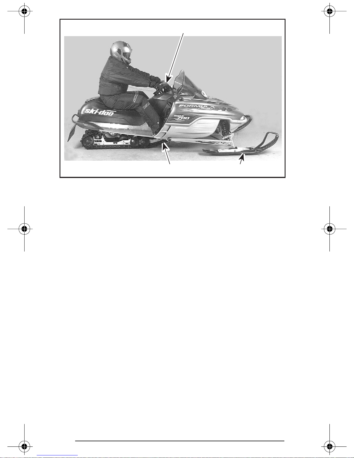
1
A32F0EB
TYP ICA L — GOOD ADJUSTMENT AT FULL ACCELERATION
1. Comfortable steering
2. Good weight transfer to the track
3. Light pressure of skis on the ground
23
56
Page 59
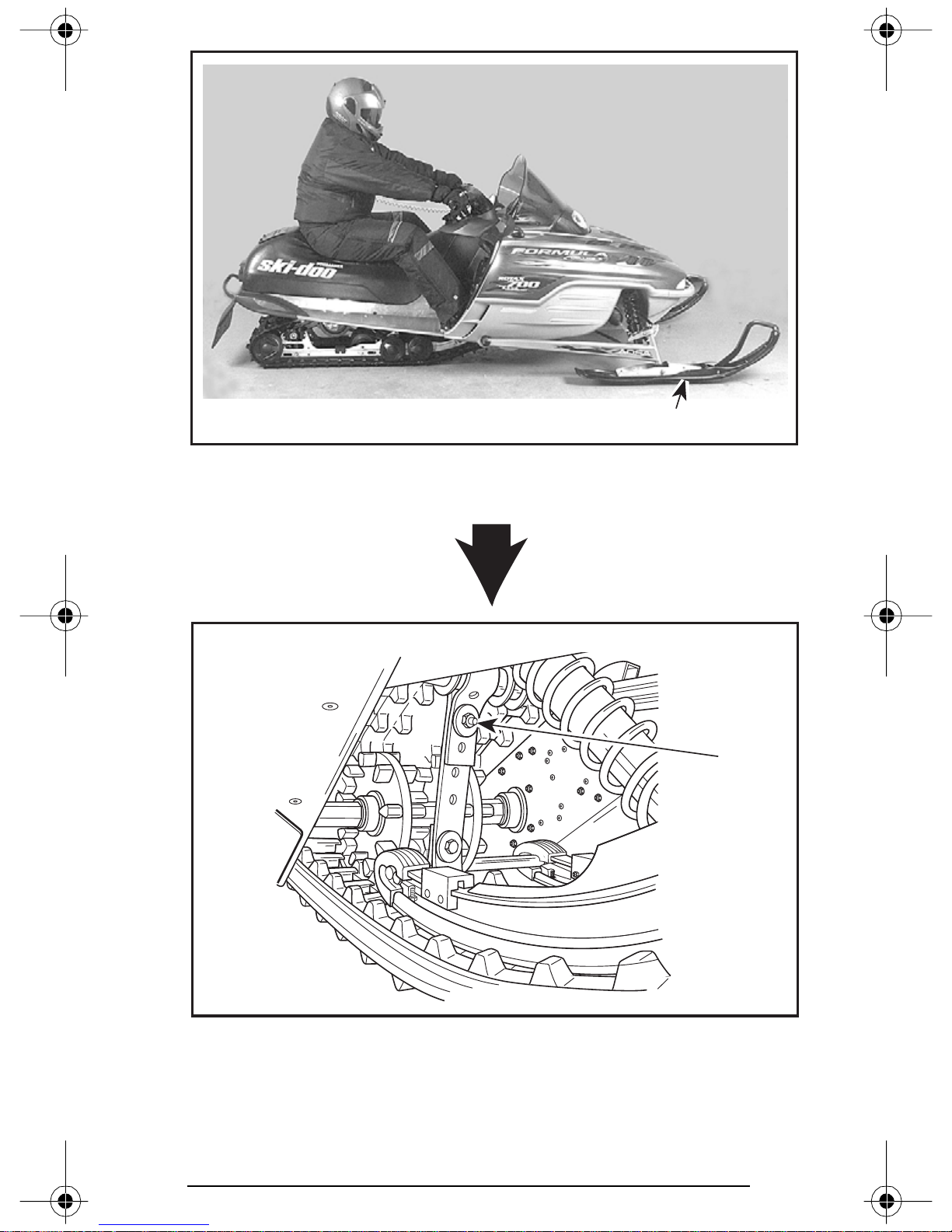
A32F0EC
TYP ICA L — TOO LONG STRAP
1. Skis lift off the ground
1
1
A03F0QB
TYP ICA L
1. Reduce strap length by bolting to a different hole
57
Page 60
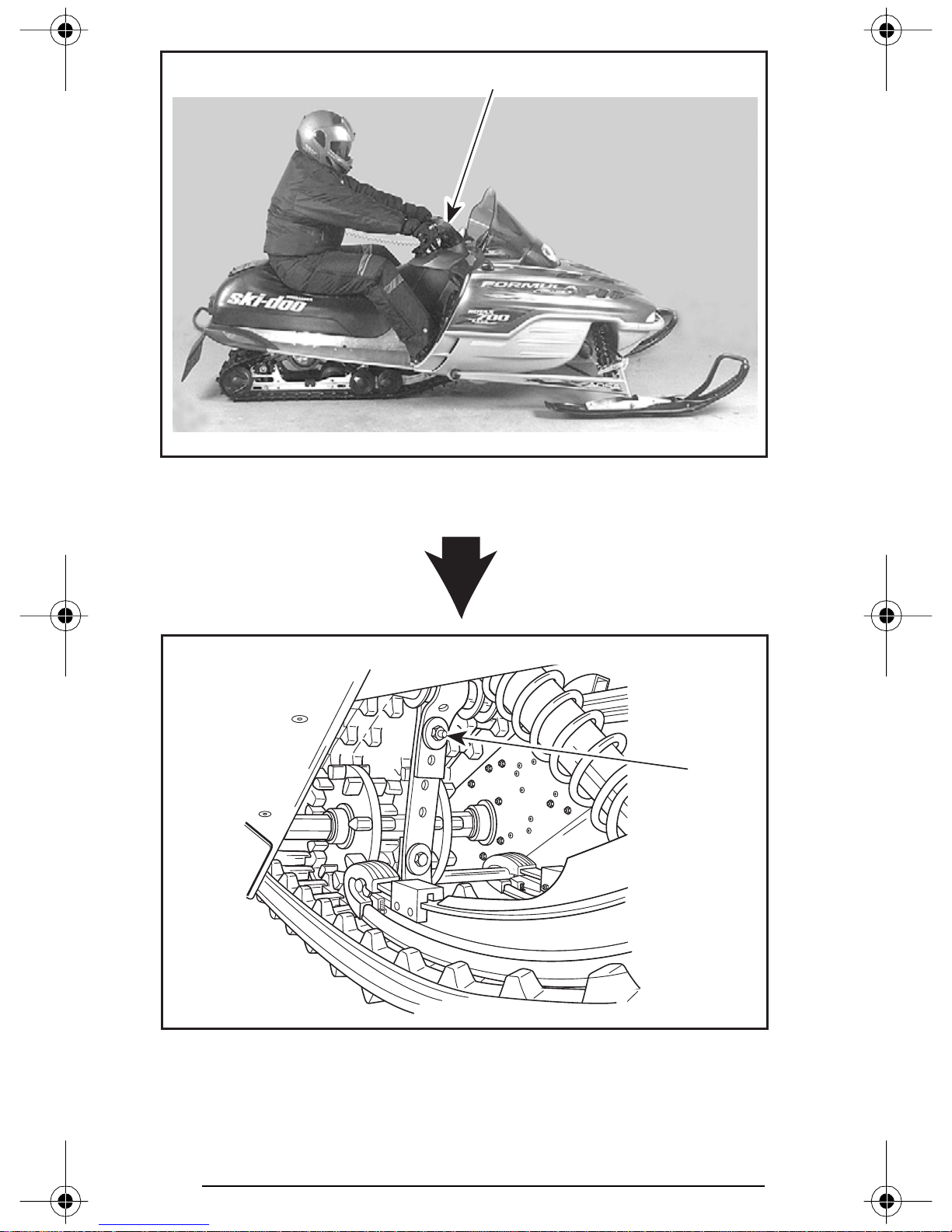
A32F0EA
TYP ICA L — TOO SHORT STRAP
1. Heavy steering
1
A03F0QB
TYP ICA L
1. Increase strap length by bolting to a different hole
58
1
Page 61
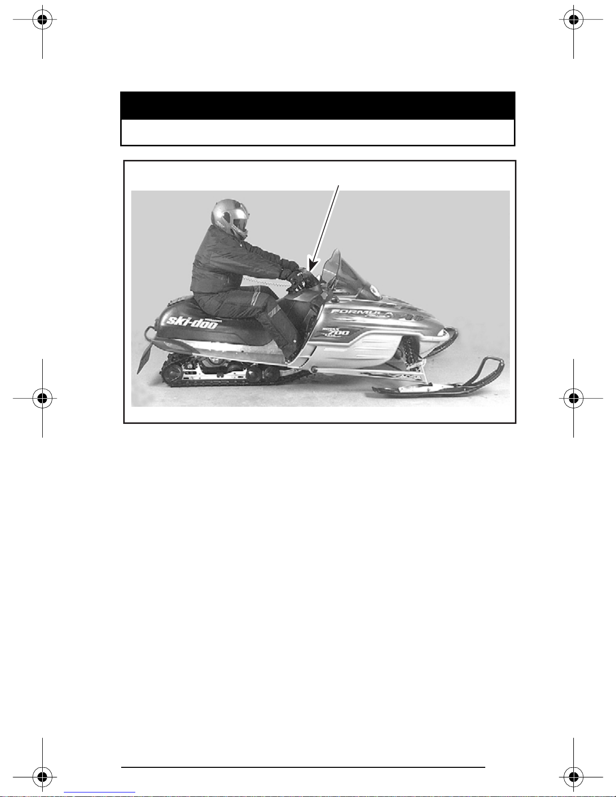
5. Front Springs — Handling
Ride at moderate speed and check for proper handling.
Adjust front springs accordingly.
WARNING
Always adjust both front springs to same position.
1
A32F0EA
TYP ICA L — PROPER ADJUSTMENT
1. Good handling and comfortable steering
59
Page 62
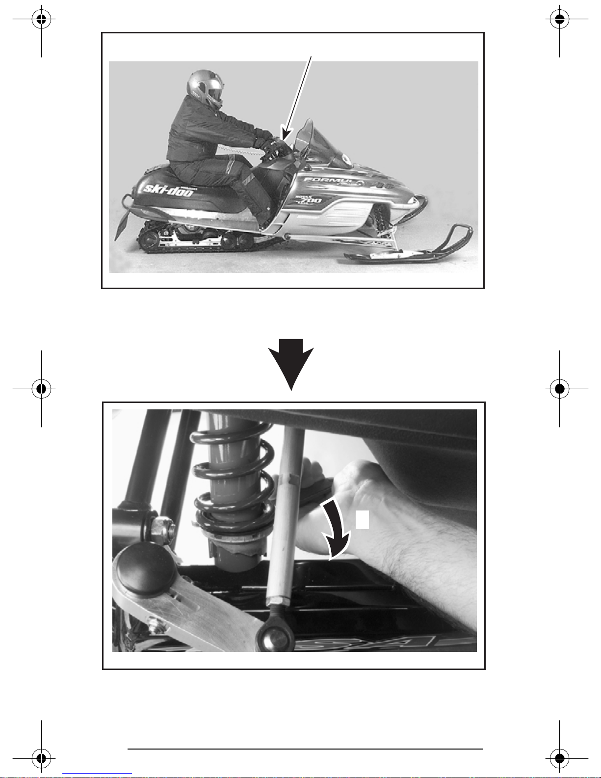
A32F0EA
TOO SOFT OF ADJUSTMENT
1. Bad handling
1
A03F2IA
1. Increase spring preload
60
1
Page 63
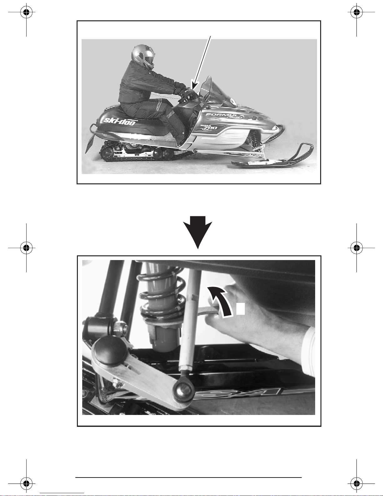
A32F0EA
TOO HARD OF ADJUSTMENT
1. Steering hard to turn
1
A03F2JA
1. Decrease spring preload
1
61
Page 64
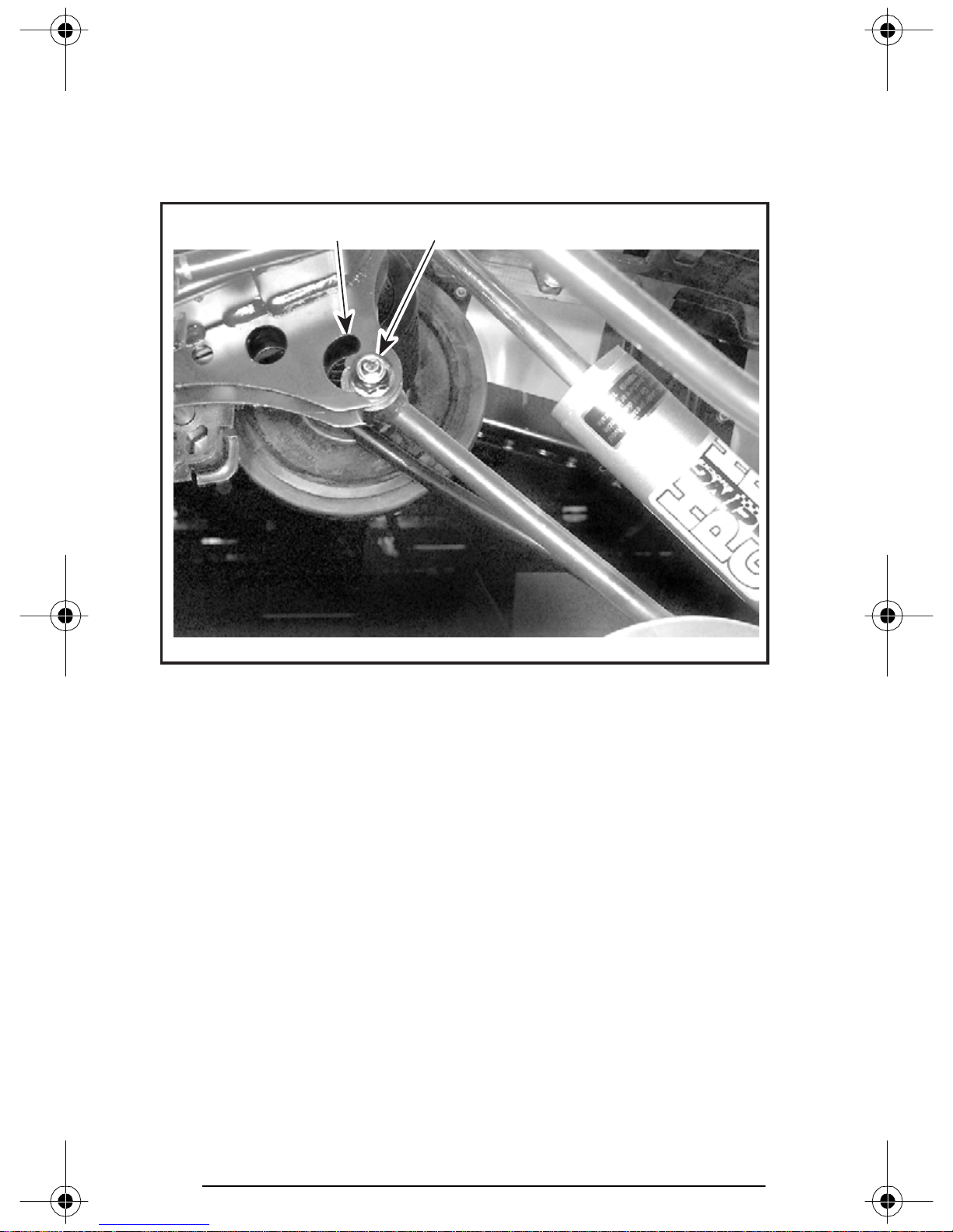
6. Rear Shock Motion Ratio — Damping Strength
Some Models Only
Rear shock motion ratio can be adjusted according to driver and passenger weight and/or trail condition.
There are two adjustment positions.
1 2
A32F0HA
1. Soft position
2. Firm position
To adjust, loosen nut, move bolt to desired position then torque nut to
24 N•m (18 lbf•ft).
62
Page 65

TROUBLESHOOTING CHART
PROBLEM CORRECTIVE MEASURES
Front suspension
wandering
Snowmobile seems
unstable and seems
to pivot around its
center
Steering feels too
heavy
Rear of snowmobile
seems too stiff
– Check ski alignment and camber angle
adjustment. See an authorized SKI-DOO dealer.
– Reduce ski ground pressure.
• Reduce front suspension spring preload.
• Increase center spring preload.
• Reduce rear spring preload.
– Reduce rear suspension front arm pressure.
• Reduce center spring preload.
• Increase rear spring preload.
• Increase front suspension spring
preload.
– Reduce ski ground pressure.
• Reduce front suspension spring preload.
• Increase center spring preload.
– Reduce rear spring preload.
Rear of snowmobile
seems too soft
Rear suspension
front shock absorber
is frequently
bottoming
Track slides too
much at start
– Increase rear spring preload.
– Lengthen stopper strap.
– Increase center spring preload.
– Lengthen stopper strap.
– Change driving position.
– Turn coupling blocks.
In Deep Snow
When operating the snowmobile in deep snow, it may be necessary
to vary the position of front spring, rear suspension, stopper strap
and/or riding position, to change the angle at which the track rides on
the snow. Operator’s familiarity with the various adjustments as well
as snow conditions will dictate the most efficient combination.
63
Page 66
FUEL AND OIL
Recommended Fuel
Use super unleaded gasoline, available from most service stations or
oxygenated fuel containing less than 10% of ethanol or 5% of methanol. The fuel used must have an octane number (R + M)/2 of 91 or
higher.
NOTE: In most service station pump octane number corresponds to
(R + M)/2 octane number.
CAUTION: Never experiment with other fuels. The use of unrecommended fuel can result in snowmobile performance deterioration and damage to critical parts in the fuel system and engine
components. Do not mismatch oil reservoir cap with fuel tank
cap. Install cap that is identified OCTANE RATING OF 91 RECOMMENDED.
WARNING
Fuel may be pressurized, open cap slowly. Fuel is flammable
and explosive. Never use an open flame to check fuel level.
Never smoke or allow flame or spark in vicinity. Never top up
the fuel tank before placing the vehicle in a warm area. As
temperature increases, fuel expands and may overflow. Always wipe off any fuel spillage from the vehicle.
Fuel System Antifreeze
When using oxygenated fuel, additional gas line antifreeze or water
absorbing additives are not required and should be not used.
When using non-oxygenated fuel, we highly recommend the use of
isopropyl base gas line antifreeze in a proportion of 150 mL (5 U.S. oz)
of gas line antifreeze added to 40 liters (10-1/2 U.S. gal) of gas.
This precaution is in order to reduce the risk of frozen carburetor(s)
which may lead, in certain cases, to high fuel consumption or severe
damage to engine.
IMPORTANT: Use only methyl hydrate free gas line antifreeze,
Kleen-Flo* or equivalent.
64
Page 67
Recommended Oil
CAUTION: Use only oil that flows at - 40°C (- 40°F). Do not mis-
match oil reservoir cap with fuel tank cap. Oil reservoir cap is
identified OIL.
Oil is contained in the oil injection reservoir.
Use only two-stroke engine injection oil sold by authorized SKI-DOO
dealers.
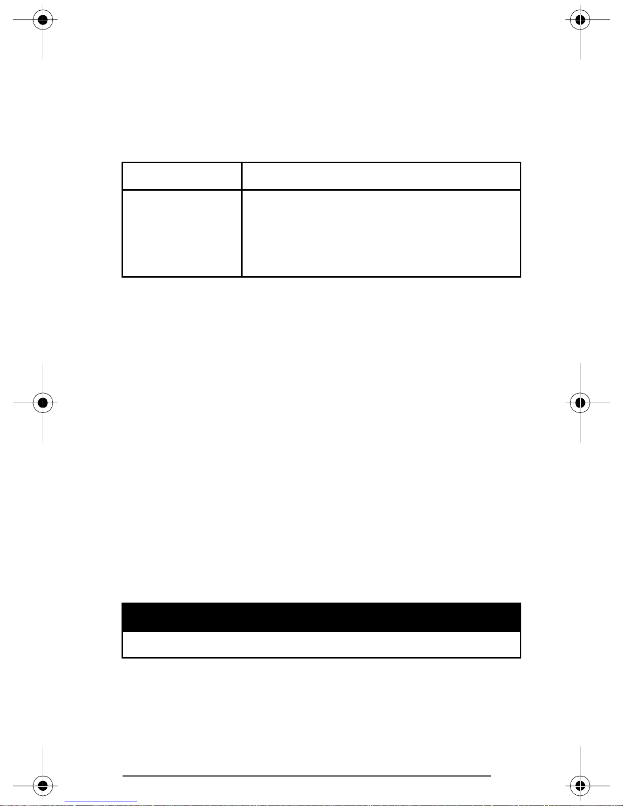
MODEL OIL TYPE
BOMBARDIER Formula XP-S synthetic
injection oil (or equivalent)
All
BOMBARDIER injection oil (or equivalent)
➀ If BOMBARDIER injection oil is not available, API TC high-quality
ashless two-stroke injection oil may be used.
➁ BOMBARDIER Formula XP-S synthetic injection oil and BOMBAR-
DIER injection oil are compatible, they can be mixed together.
OR
➀ ➁
BOMBARDIER injection oil is a special blend of basic oil and additives
especially selected to ensure unequalled lubrication, engine cleanliness
and minimum spark plug fouling.The BOMBARDIER Formula XP-S
synthetic injection oil provides superior lubrication, reduced en-
gine component wear and oil deposit, thus maintaining maximumlevel performance and antifriction properties. This synthetic injection
oil meets the latest ASTM and JASO standards by ensuring high biodegradability and low exhaust smoke.
CAUTION: Never use four-stroke petroleum or synthetic motor
oil and never mix these with outboard motor oil. Do not use
NMMA TC-W, TC-W2 or TC-W3 outboard motor oils. Avoid mixing different brands of API TC oil as resulting chemical reactions
may cause severe engine damage.
Always maintain a sufficient amount of recommended oil in the injection oil reservoir.
Wipe off any oil spills. Oil is highly flammable.
WARNING
CAUTION: Check level and refill every time you refuel. Do not
mismatch oil reservoir cap with fuel tank cap. Install cap that is
identified OIL.
65
Page 68

COLD WEATHER CARBURETION
MODIFICATIONS
All vehicles have been calibrated for - 20°C (- 4°F). They can be operated at warmer winter temperatures without problems.
CAUTION: For colder temperatures than - 20°C (- 4°F), carbure-
tor(s) must be recalibrated to avoid engine damage. Refer to an
authorized SKI-DOO dealer.
Refer also to RIDING AT HIGH ALTITUDES in following pages.
BREAK-IN PERIOD
Engine
CAUTION: A break-in period of 10 operating hours — 500 km
(300 miles) — is required before running the snowmobile at full
throttle.
During break-in period, maximum throttle should not exceed 3/4.
However, brief full acceleration and speed variations contribute to a
good break-in. Continued wide open throttle accelerations, prolonged
cruising speeds and engine overheating are detrimental during the
break-in period.
To assure additional protection during the initial engine break-in,
500 mL (18 imp. oz) of recommended injection oil, should be added
to fuel for the first full filling of fuel tank. Always remove and clean
spark plugs after engine break-in.
Belt
A new drive belt requires a break-in period of 50 km (30 miles). Avoid
strong acceleration/deceleration, pulling a load or high speed cruising.
10-Hour Inspection
As with any precision piece of mechanical equipment, we suggest
that after the first 10 hours of operation — 500 km (300 miles) — or
30 days after the purchase, whichever comes first, your snowmobile
be checked by an authorized SKI-DOO dealer. This inspection will
give you the opportunity to discuss the unanswered questions you
may have encountered during the first hours of operation.
The 10-hour inspection is at the expense of the snowmobile owner.
66
Page 69
PRE-OPERATION CHECK
The pre-operation check is very important prior to operating
the vehicle. Always check the proper operation of critical controls, safety features and mechanical components before starting. If not done as specified here, severe injury or death might
occur.
• Verify that track and idler wheels are unfrozen and free to turn.
Always use a mechanical snowmobile stand to properly support vehicle during any track verification. Slowly accelerate engine in order to rotate track at very low speed when it is not on
ground.
• Activate the brake control lever and make sure the brake fully applies before the brake control lever touches the handlebar grip. It
must fully return when released.
• Check the parking device. Apply parking brake and check if it operates properly.
WARNING
WARNING
• Activate the throttle control lever several times to check that it
operates easily and smoothly.
WARNING
Throttle lever must operate easily and smoothly. It must return to idle position when released.
• Check operation of headlight switch (HI-LO), taillight, brake light,
indicator lights and tether and engine cut-out switches.
• Verify that skis and steering operate freely. Check corresponding
action skis versus handlebar.
• Check fuel and injection oil for levels and leaks. Replenish as necessary and see an authorized SKI-DOO dealer in case of any leaks.
• Verify that air filter(s) is free of snow and ice, if so equipped.
All adjustable features should be positioned at optimal setting.
Securely tighten all adjustment locks.
WARNING
• All storage compartments must be properly latched and they must
not contain any heavy or breakable objects.
67
Page 70

PRE-OPERATION CHECK LIST
ITEM OPERATION ✔
Track and idler wheels Check for free movement.
Brake lever Check proper action.
Parking device Check proper action.
Throttle lever Check proper action.
Switches and lights Check proper action.
Skis and steering Check proper action.
Fuel and oil
Check for proper level and
leaks.
Air filter Check for free of snow and ice.
Check for optimal adjustment
Adjustable features
and securely tightened adjustment locks.
Storage compartment
Check for proper latching and no
heavy or breakable objects.
68
Page 71
OPERATING INSTRUCTIONS
Proceed with pre-operation check list before riding.
WARNING
Principle of Operation
Propulsion
Depressing throttle lever increases engine RPM causing the drive
pulley to engage. For most models engine RPM must be between
2500 and 4200 before drive pulley engagement will occur.
Outer sheave of drive pulley moves toward inner sheave, forcing
drive belt to move upward on the drive pulley and simultaneously
forcing the sheaves apart on the driven pulley.
The driven pulley senses the load on the track and limits the belt
movement. The result is a continuous change in the ratio of the two
pulleys which maximizes acceleration and forward movement of the
vehicle.
WARNING
Do not operate engine with hood open or belt guard removed.
Power is transferred to the track through the chaincase and drive axle.
Always use a mechanical snowmobile stand to properly support vehicle during any track verification. Slowly accelerate engine in order to rotate track at very low speed when it is not on
ground.
Tur n in g
Handlebar controls the direction of travel of the vehicle. As the handlebar is rotated to right or left, the skis are turned in the direction of
intended travel.
Fast reverse could result in loss of stability.
WARNING
WARNING
69
Page 72
Starting the Engine
Operator and passenger (if applicable) must be properly seated
before starting engine.
• Re-check throttle control lever operation.
• Ensure that engine cut-out switch is in the ON position.
• Ensure that tether cord cap is set in place and that cord is attached
to your clothing.
Initial Cold Starting
NOTE: Do not operate the throttle lever during starting.
When Temperature is Below - 10°C (+ 15°F)
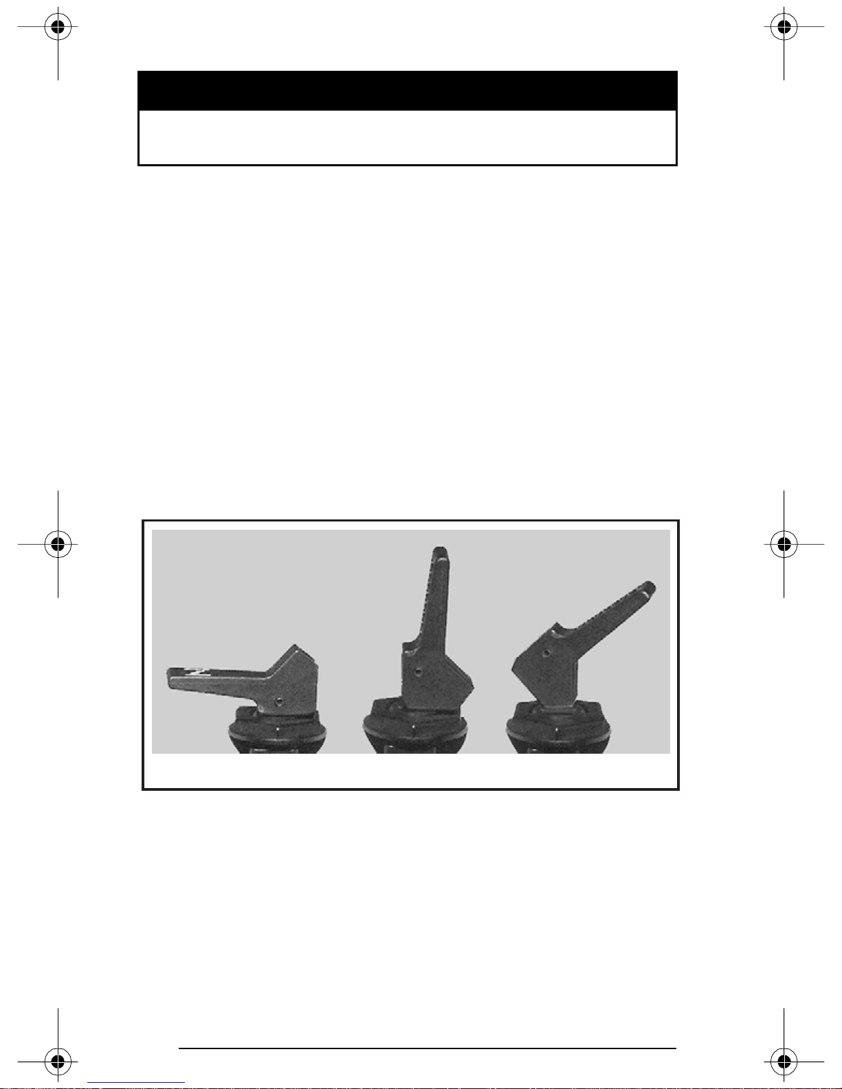
Set the choke lever to the second position.
Grasp starter handle firmly and crank engine or use electric starter
on so equipped models.
After the engine is started, close off choke to ensure proper air-fuel
mix when speed drops below 2000 RPM.
WARNING
A32H01A
0. OFF
1. Position 1
2. Position 2
When Temperature is Above - 10°C (above + 15°F)
Set the choke lever to the first position.
Grasp starter handle firmly and crank engine.
After the engine is started, close off choke to ensure proper air-fuel mix.
70
01 2
Page 73
Warm Engine Starting
Start the engine without any choke. If the engine will not start after
two pulls of the rope or two 5 second attempts with the electric
starter move choke lever to position 1. Start the engine without activating the throttle lever. As soon as the engine starts move the choke
lever to OFF.
Manual Starting
Install tether cord cap on DESS post. Turn on engine cut-out switch.
Grasp manual starter handle firmly and crank engine.
WARNING
Do not apply throttle while starting.
Emergency Starting
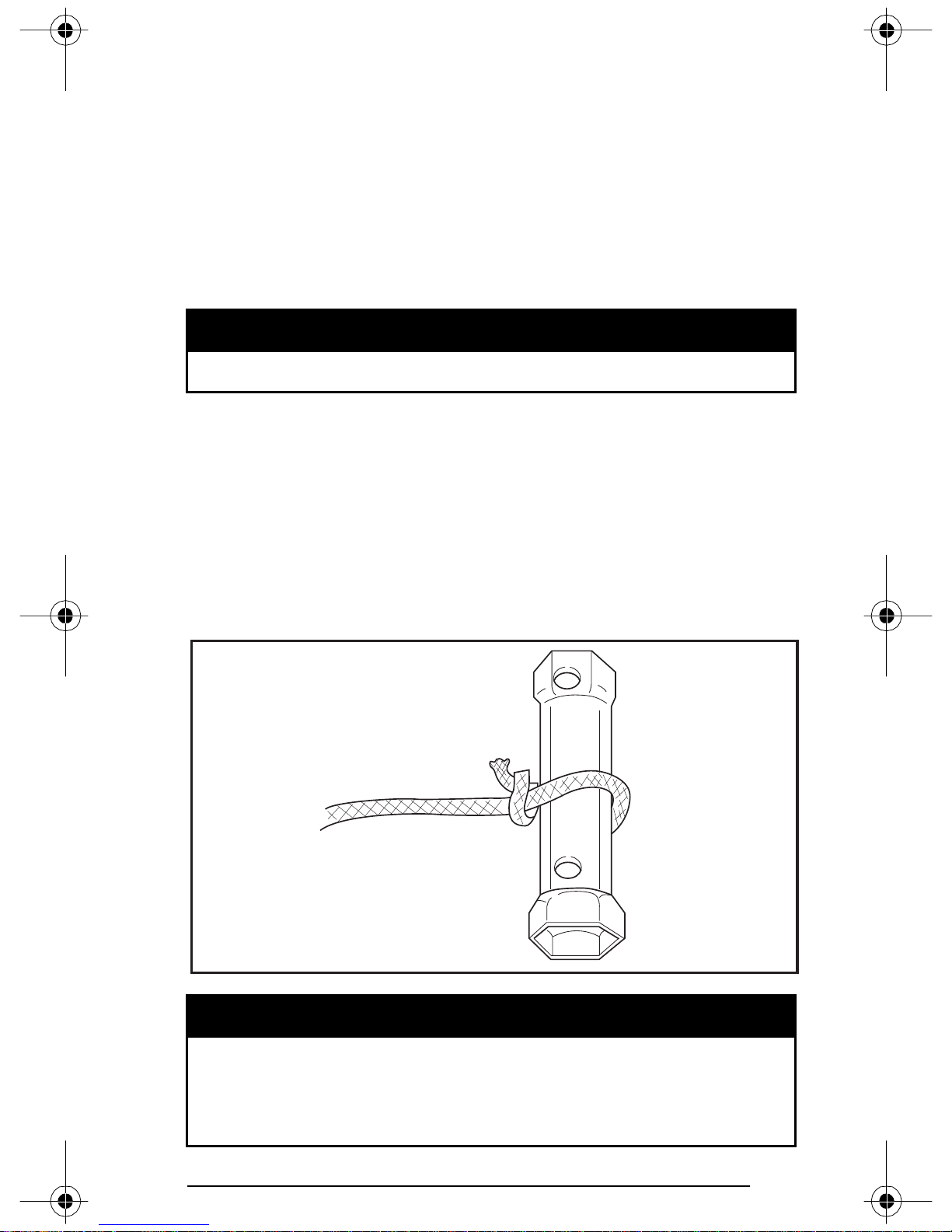
The engine can be started with the emergency starter rope supplied
with the tool kit.
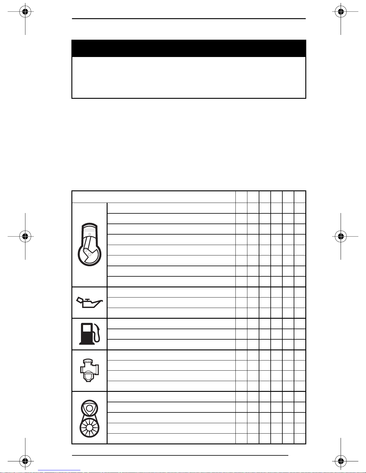
Remove belt guard.
Attach emergency rope to rewind handle and to the starter clip sup-
plied in the tool box.
Use the spark plug socket as an emergency handle.
A17B01A
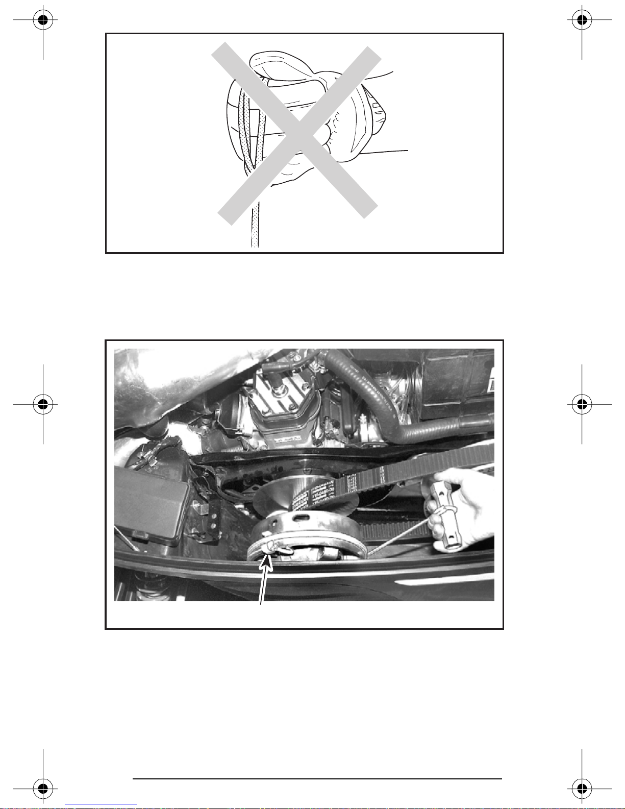
Do not wind starting rope around your hand. Hold rope by the
handle only. Do not start the snowmobile by the drive pulley
unless it is a true emergency situation. Have the snowmobile
repaired as soon as possible.
WARNING
71
Page 74
A07D0UA
Tie a knot near clip. Hook up clip on drive pulley and wind counterclockwise up to 3 turns.
Wind the rope tightly around drive pulley. When pulled, pulley must
rotate counterclockwise.
A30D06A
1. Clip
Start engine as described in COLD ENGINE STARTING or WARM
ENGINE STARTING according to engine temperature.
Pull the rope using a sharp, crisp pull so the rope comes free of the
drive pulley.
72
1
Page 75

WARNING
When starting the snowmobile in an emergency situation using drive pulley, do not reinstall the belt guard and return
slowly to have snowmobile repaired.
Shutting Off the Engine
Release throttle lever and wait until engine has returned to idle speed.
Shut off the engine using either engine cut-out switch or tether cut-
out switch.
Never leave tether cord on vehicle when not in operation.
WARNING
VEHICLE WARM-UP
Before every ride, vehicle has to be warmed up as follows.
Snowmobile must be securely supported by the rear bumper using
a mechanical snowmobile stand. Track must be 100 mm (4 in) off the
ground.
Start engine and allow it to warm up two or three minutes at idle
speed.
Release parking brake.
WARNING
Make sure mechanical snowmobile stand is stable. Stay clear
of the front of vehicle and the track. Do not use too much throttle during warm-up or when track is free-hanging.
Apply throttle until drive pulley engages. Let track rotate at low speed
for several turns. The lower the vehicle temperature is the longer
vehicle warm-up should be.
Shut-off the engine and remove the snowmobile mechanical stand.
Skis may be frozen on the ground. Grasp both skis by their loops and
lift them.
After restarting engine, the vehicle must be driven at low speed for
the first 2 or 3 minutes. After that, it may be driven up to the legal
speed limit as per normal safety practices.
73
Page 76

POST-OPERATION CARE
Shut off the engine. Install rear of vehicle on a snowmobile mechanical stand.
Remove snow and ice from rear suspension, track, front suspension,
steering mechanism and skis.
Protect vehicle with a snowmobile cover.
SPECIAL OPERATIONS
Riding at High Altitudes
If you ride at altitudes above 600 m (2000 ft), your snowmobile should
have modifications. Refer to an authorized SKI-DOO dealer.
CAUTION: Do not change original factory calibration if snowmobile is used below 600 m (2000 ft).
Engine Overheating
Reduce snowmobile speed and run snowmobile in loose snow or
stop engine immediately.
Check for adequate coolant level. See an authorized SKI-DOO dealer.
Fuel Flooded Engine
All Models
Do not hold throttle partially or fully open when starting a fuel
flooded engine.
Install new spark plugs and restart engine.
WARNING
Rear Suspension Slider Shoe Starts Sticking
All Models
Slider shoes are cooled and lubricated by snow. When riding at moderate or high speed on a thin-snow-covered surface, slider shoes may
stick on track metallic guides.
Run snowmobile on a surface covered by snow or drive snowmobile
at very slow speed.
Have slider shoes inspected by an authorized SKI-DOO dealer.
74
Page 77
PERIODIC MAINTENANCE CHART
Observe WARNINGS and CAUTIONS mentioned throughout
this guide which are pertinent to the item being checked. When
component conditions seem less than satisfactory, replace
with genuine BOMBARDIER parts or approved equivalents.
Some items may not apply to your particular model. Refer to LUBRICATION and MAINTENANCE in Shop Manual for more details.
➀ 10-HOUR OR 500 km (300 miles) INSPECTION
(To be performed by SKI-DOO dealer)
➁ WEEKLY OR EVERY 240 km (150 miles)
➂ MONTHLY OR EVERY 800 km (500 miles)
➃ ONCE A YEAR OR EVERY 3200 km (2000 miles)
➄ STORAGE (To be performed by SKI-DOO dealer)
➅ PRE-SEASON PREPARATION (To be performed by SKI-DOO dealer)
PERIODIC MAINTENANCE CHART ➀➁➂➃➄➅
Starting Rope Condition ✓✓
Engine Head Screws ✓✓✓
WARNING
Engine Mount Nuts or Screws ✓✓✓
Exhaust System ✓✓✓
Engine Lubrication ✓
Cooling System Condition ✓✓✓
Coolant Replacement ✓✓
Condition of Seals ✓✓
Injection Oil Filter Condition ✓
Injection Oil Filter Replacement ✓
Oil Injection Pump Adjustment ✓✓
Fuel Stabilizer ✓
Fuel Filter Replacement ✓
Fuel Lines and Connections ✓✓✓
Carburetor Adjustment ✓✓✓
Carburetor Cleaning ✓
Throttle Cable Inspection ✓ ✓✓✓
Air Filter Cleaning ✓✓
Drive Belt Condition ✓✓ ✓
✓
Condition of Drive and Driven Pulleys ✓✓✓
Cleaning of Drive and Driven Pulleys ✓
Retorquing of Drive Pulley Screw ✓
Driven Pulley Preload ✓✓✓
75
Page 78
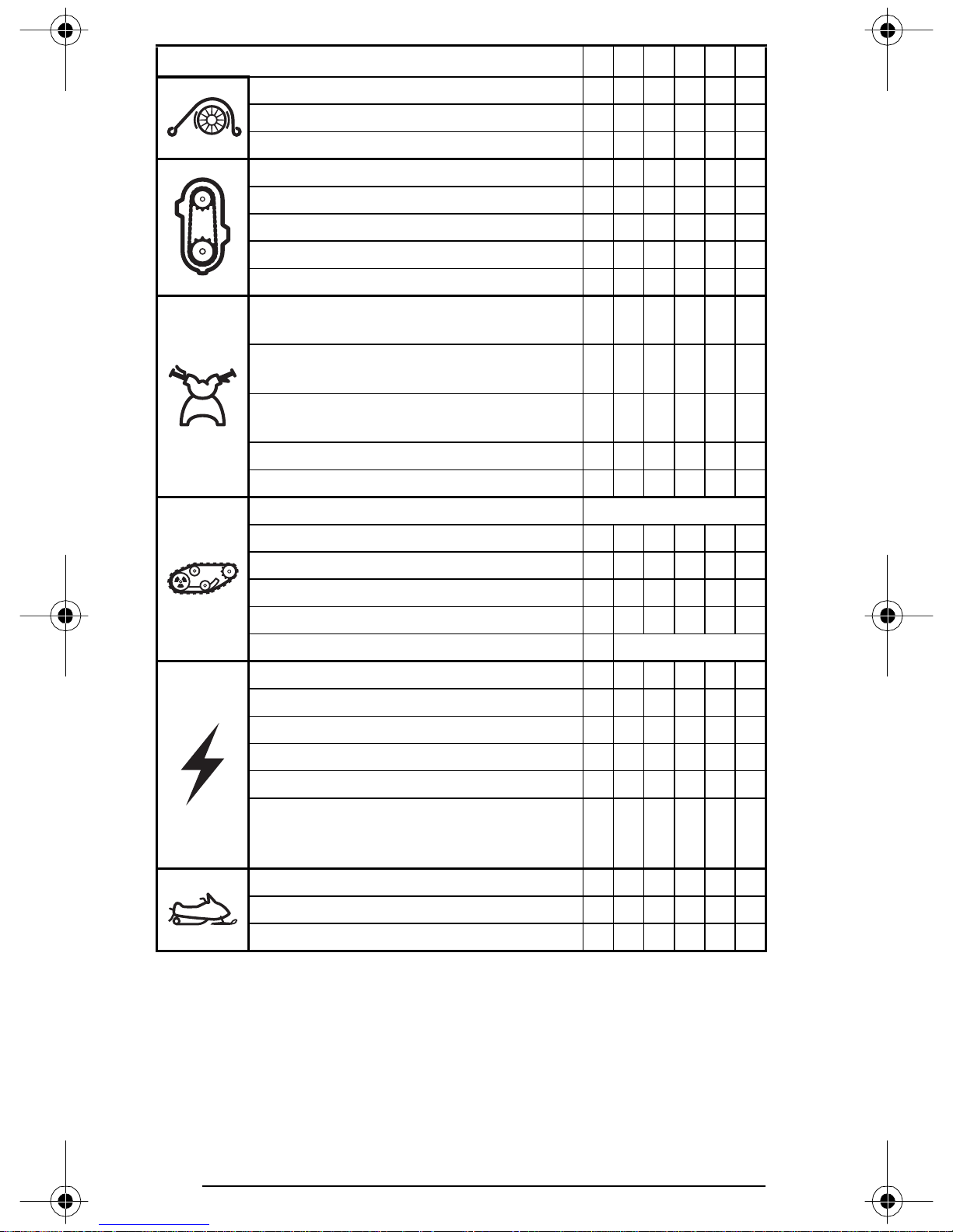
PERIODIC MAINTENANCE CHART ➀➁➂➃➄➅
Brake Fluid Level ✓✓ ✓
Brake Fluid (change once a year) ✓
Brake Condition ✓✓ ✓✓
Drive Chain Tension ✓✓✓
Countershaft Lubrication** ✓✓✓
Chaincase Oil Level ✓✓ ✓
Chaincase Oil Change
✔
✓
Lubrication of Drive Axle End Bearing** ✓✓✓
Handlebar Bolts, Retorque to 26 N•m
(19 lbf•ft)
Steering and Front Suspension Mechanism
Lubrication**
Steering and Front Suspension Mechanism
Condition
✓✓
✓✓✓
✓✓✓
Wear and Condition of Skis and Runners ✓✓ ✓
Steering and Ski Leg Camber Adjustment ✓✓✓
Suspension Adjustments
AS REQUIRED
Suspension Lubrication** ✓✓
Suspension Condition ✓ ✓✓✓
Suspension Stopper Strap Condition ✓✓
Track Condition ✓✓✓
Track Tension and Alignment ✓
AS REQUIRED
Spark Plugs* ✓✓ ✓
Engine Timing ✓✓
Battery Condition ✓✓✓✓
Headlight Beam Aiming ✓✓
Wiring Harnesses, Cables and Lines ✓✓✓
Operation of Lighting System (HI/LO Beam,
Brake Light, etc.) Test Operation of Engine
✓✓ ✓
Cut-Out Switch and Tether Cut-Out Switch
Rags in Air Intake and Exhaust System ✓✓
Engine Compartment ✓✓✓
Vehicle Cleaning and Protection ✓✓✓
** Before installing new properly gapped spark plugs at pre-season
preparation, it is suggested to burn excess storage oil by starting
the engine with the old spark plugs. Only perform this operation
in a well ventilated area.
** Lubricate whenever the vehicle is used in wet conditions (wet snow,
rain, puddles).
76
Page 79
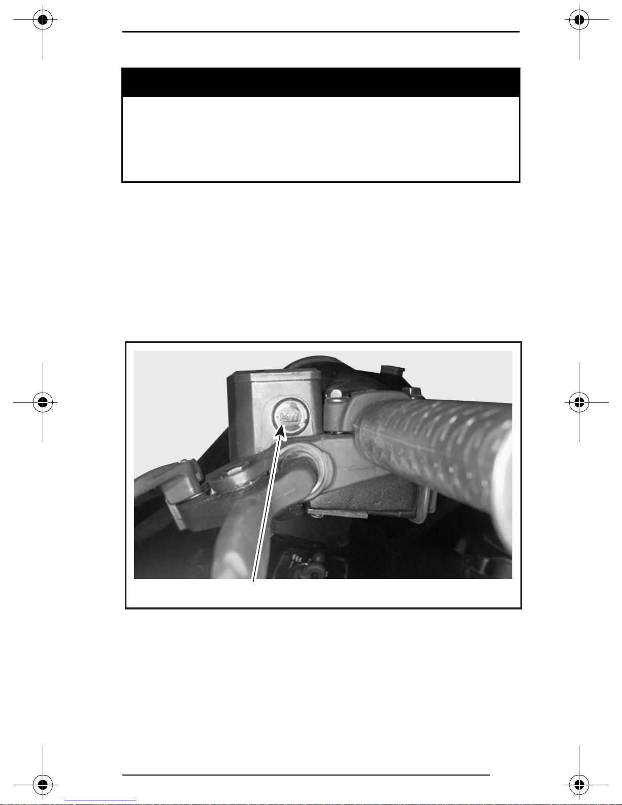
FLUID LEVELS
It is recommended that the assistance of an authorized SKI-DOO
dealer be periodically obtained on other components/systems
not covered in this guide. Unless otherwise specified, engine
must be cold and not running. The tether cord cap must be removed for all maintenance procedures.
CAUTION: Vehicle must be on a level surface before checking any
fluid levels.
WARNING
Brake System
Check brake fluid (DOT 4) in reservoir for minimum level. Add fluid
(DOT 4) as required.
CAUTION: Use only (DOT 4) brake fluid from a sealed container.
Never use any other types of fluid.
A30D08A
TYPICAL — BRAKE FLUID RESERVOIR
1. Minimum
1
77
Page 80
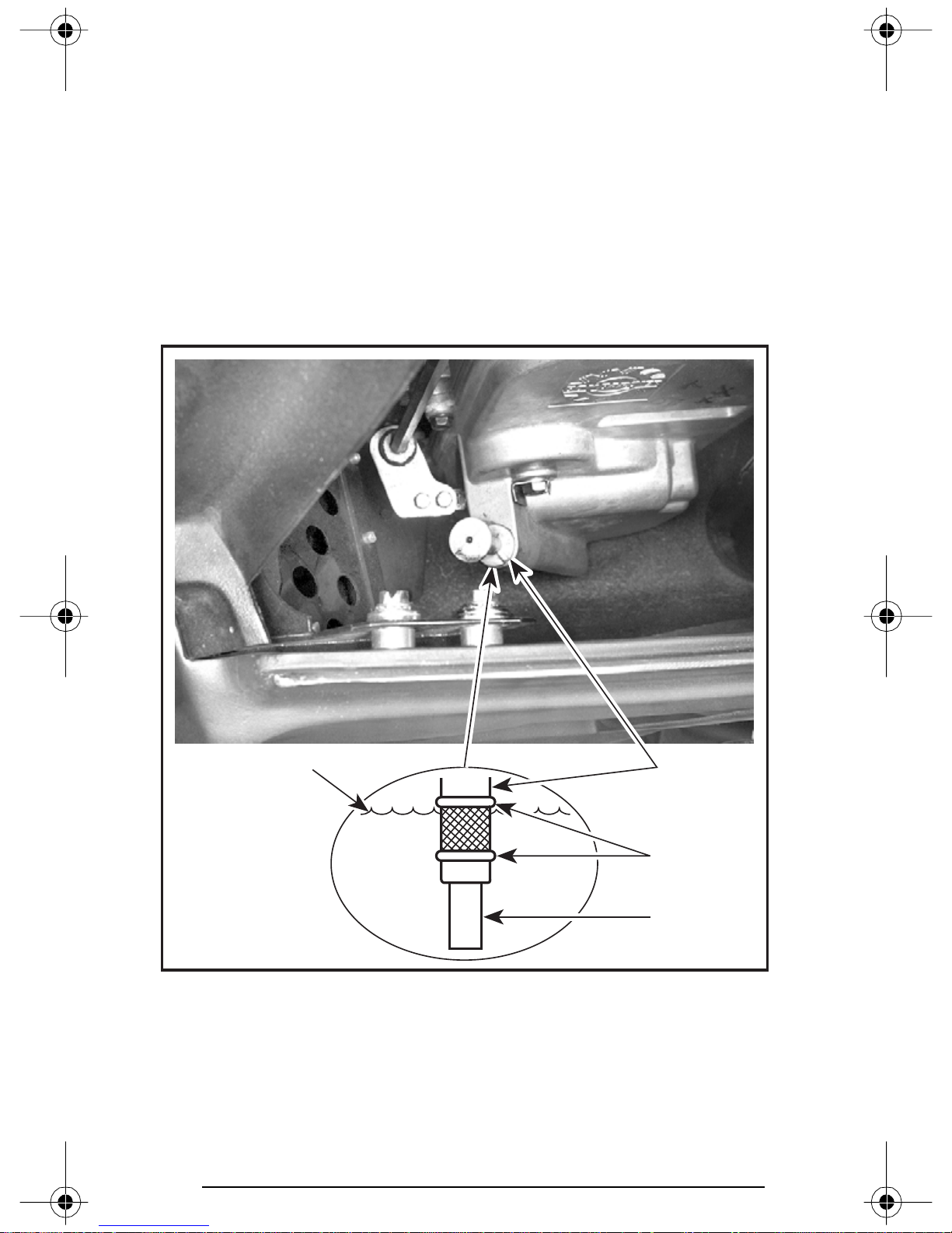
Chaincase Oil Level
With snowmobile on a level surface, check the oil level by removing
dipstick. Oil level must be between lower and upper marks.
NOTE: It is normal to find metallic particles stuck to dipstick magnet.
If bigger pieces of metal are found, see an authorized SKI-DOO dealer.
Remove metal particles from magnet.
Refill up to upper mark using BOMBARDIER synthetic chaincase oil
(P/N 413 803 300 — 12 x 355 mL).
CAUTION: Use BOMBARDIER synthetic chaincase oil or suitable
equivalent when servicing. Do not mix synthetic oil with other oils.
2
A30D0AB
TYPICAL
1. Dipstick
2. Oil level
3. Level between marks
4. Magnet
78
1
3
4
Page 81
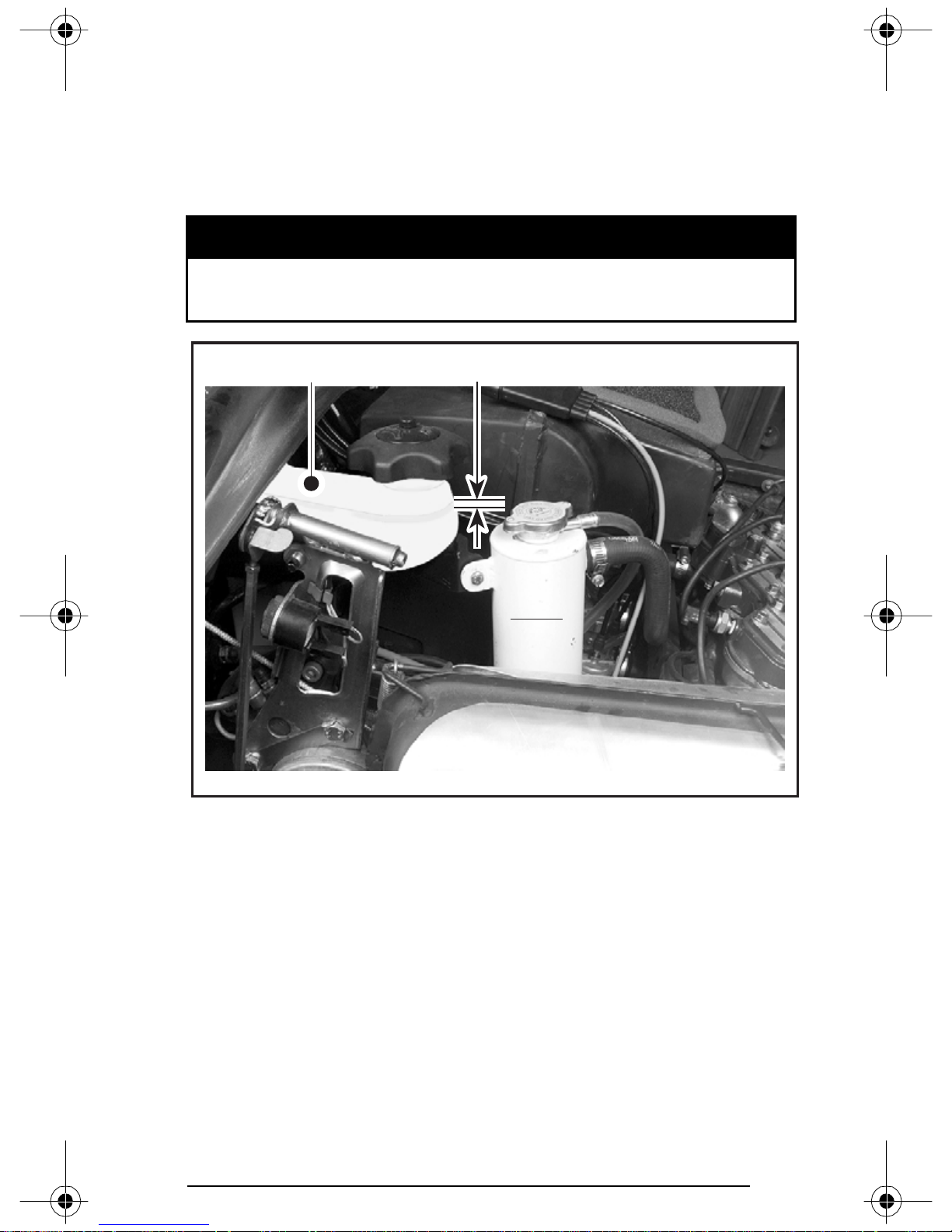
Oil Injection System
Always maintain a sufficient amount of recommended BOMBARDIER
injection oil in the injection oil reservoir.
CAUTION: Never allow oil reservoir to be almost empty. Do not
mismatch oil reservoir cap with fuel tank cap. Install cap that is
identified OIL.
WARNING
Check level and refill every time you refuel. Do not overfill.
Wipe off any spillage. Oil is highly flammable when heated.
2
A30C02A
TYPICAL
1. Maximum level: 13 mm (1/2 in) from top
2. Injection oil reservoir
1
NIVEAU FROID
COLD LEVEL
79
Page 82
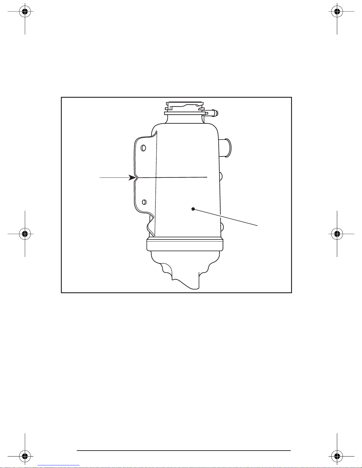
Cooling System
Check coolant level at room temperature. Liquid should be at level
mark (engine cold) of coolant tank.
NOTE: When checking level at low temperature it may be slightly lower
then mark.
If additional coolant is necessary or if entire system has to be refilled,
refer to an authorized SKI-DOO dealer.
NIVEAU
FROID
NIVEAU FROID
2
COLD
LEVEL
COLD LEVEL
A30C0ZA
1. Coolant tank
2. COLD LEVEL line
1
80
Page 83

MAINTENANCE
It is recommended that the assistance of an authorized SKI-DOO
dealer be periodically obtained on other components/systems
not covered in this guide. Unless otherwise specified, engine
must be cold and not running. The tether cord cap must be removed for all maintenance procedures.
WARNING
Vehicle Cleaning and Protection
Remove any dirt or rust.
To clean the entire vehicle, use only flannel cloths or equivalent.
CAUTION: It is necessary to use flannel cloths or equivalent on
windshield and hood to avoid damaging further surfaces to clean.
To clean the entire vehicle, including bottom pan and metallic parts use.
Bombardier Cleaner (P/N 293 110 001 (spray can 400 g) and P/N 293
110 002 (4 L)).
CAUTION: Do not use Bombardier Cleaner on decals or vinyl.
For vinyl and plastic parts use Vinyl & Plastic Cleaner (P/N 413 711 200
(6 x 1 L)).
To remove scratches on windshield or hood use BOMBARDIER Scratch
Remover Kit (P/N 861 774 800).
CAUTION: Never clean plastic parts or hood with strong detergent,
degreasing agent, paint thinner, acetone, products containing
chlorine, etc.
Clean sheaves of both pulleys using BOMBARDIER Parts Cleaner
(P/N 413 711 809).
Inspect the hood and repair any damage.
Touch up all metal spots where paint has been scratched off. Spray
all metal parts including shock chromed rods with BOMBARDIER LUBE
(P/N 293 600 016).
Wax the hood and the painted portion of the frame for better protection.
NOTE: Apply wax on glossy finish only. Protect the vehicle with a cover
to prevent dust accumulation during storage.
CAUTION: The snowmobile has to be stored in a cool and dry place
and covered with an opaque tarpaulin. This will prevent sun rays
and grime from affecting plastic components and vehicle finish.
Lift rear of vehicle until track is clear of the ground. Install on a snowmobile mechanical stand.
NOTE: Do not release track tension.
81
Page 84
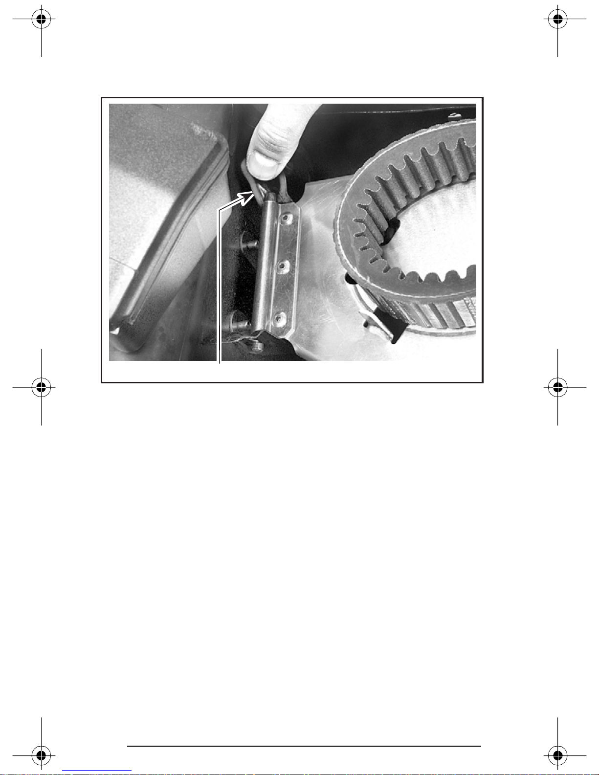
Belt Guard Removal and Installation
Turn off engine cut-out switch. Open hood.
Open retainer to release pin then pull belt guard toward front.
A30C10A
1. Pin retainer
1
When reinstalling belt guard, position its cut-away toward front of
snowmobile. Refer to decal on belt guard.
Insert belt guard slots at rear first.
82
Page 85
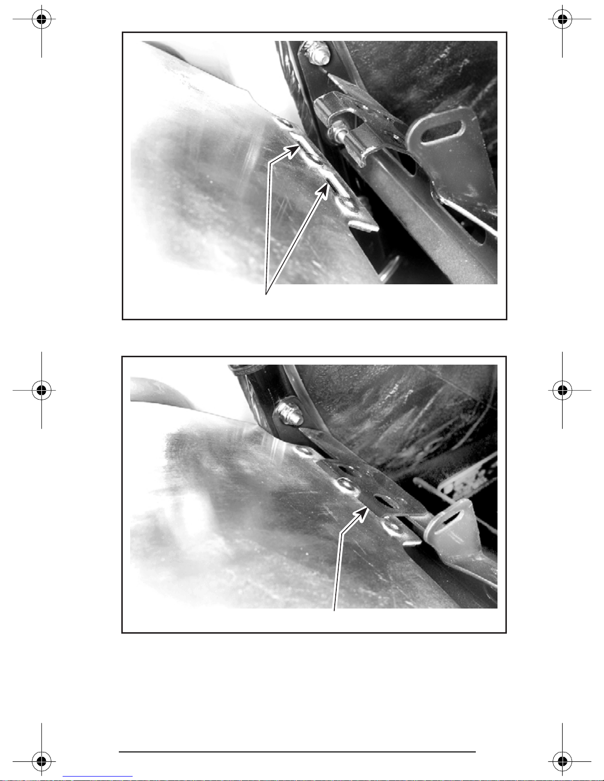
A30C06A
1. Slots
1
A30C07A
1. Rear of belt guard properly installed
Push down front portion of belt guard in retainer.
NOTE: Belt guard is purposely made slightly oversize to maintain ten-
sion on its pins and retainers preventing undue noise and vibration.
It is important that this tension be maintained when reinstalling.
1
83
Page 86
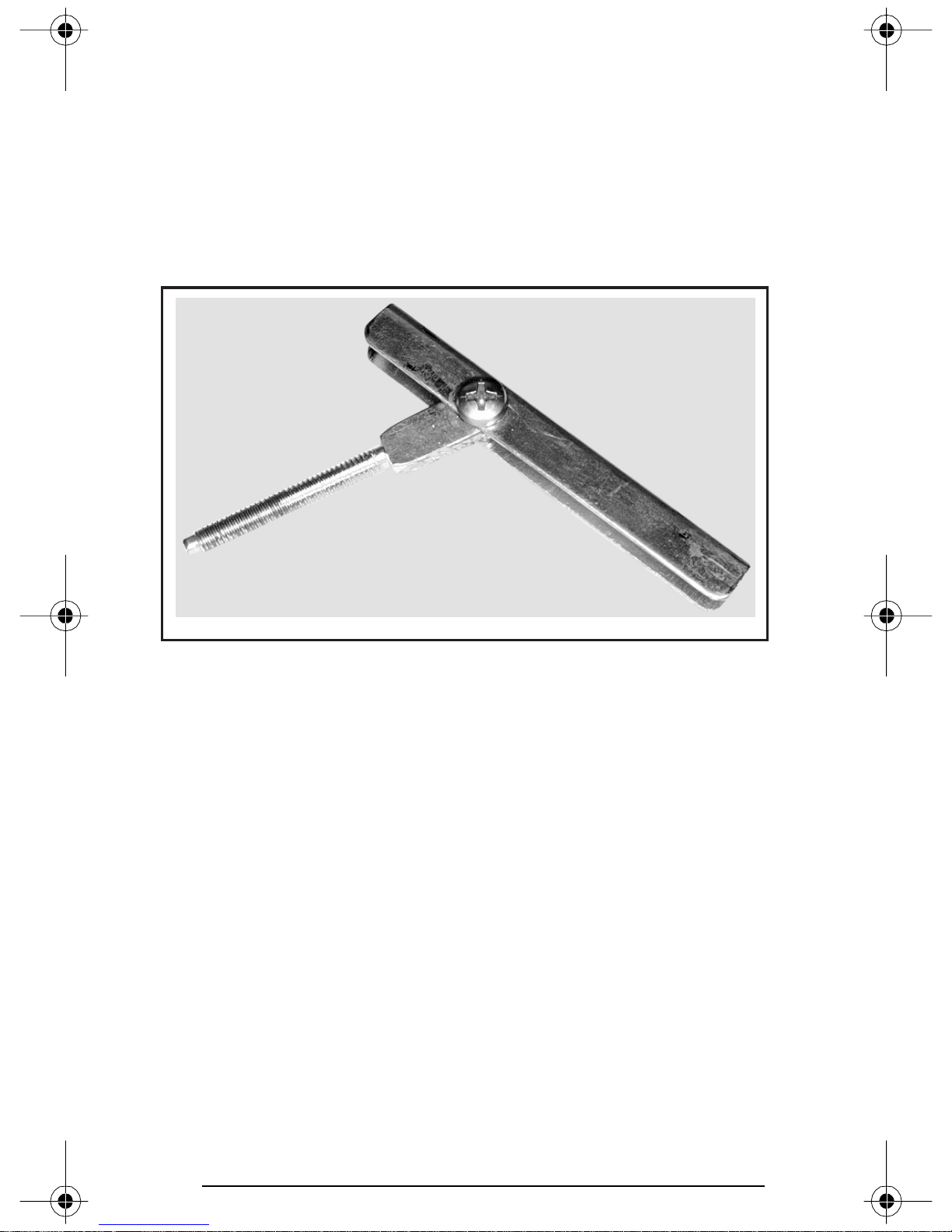
Drive Belt Removal/Installation
NOTE: Removal and installation of drive belt is easier when driven
pulley is held with brake so that it can not rotate. Apply parking brake,
for this purpose.
Turn off engine cut-out switch.
Open hood and remove belt guard.
Open the driven pulley with the drive belt installer/remover provided
in tool box.
A03D2PA
DRIVE BELT INSTALLER/REMOVER
Screw drive belt installer/remover in the free threaded hole and tighten to open the pulley. Remove belt.
84
Page 87
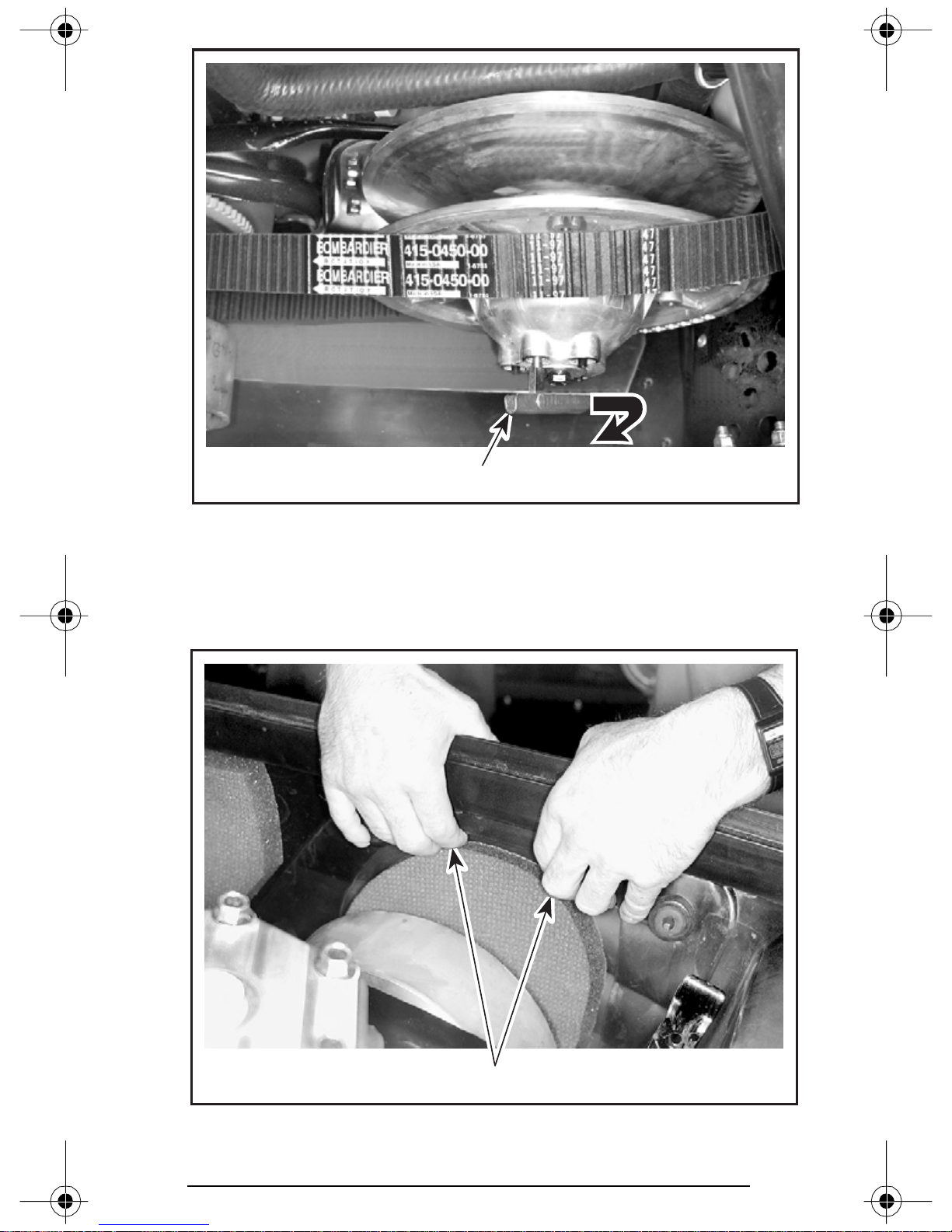
A30D0BA
1. Tighten to open pulley
1
Slip the belt over the top edge of the sliding half of driven pulley, as
shown in previous photo.
Remove access panel from bottom pan.
A30C04A
1. Push top of panel out of bottom pan
1
85
Page 88
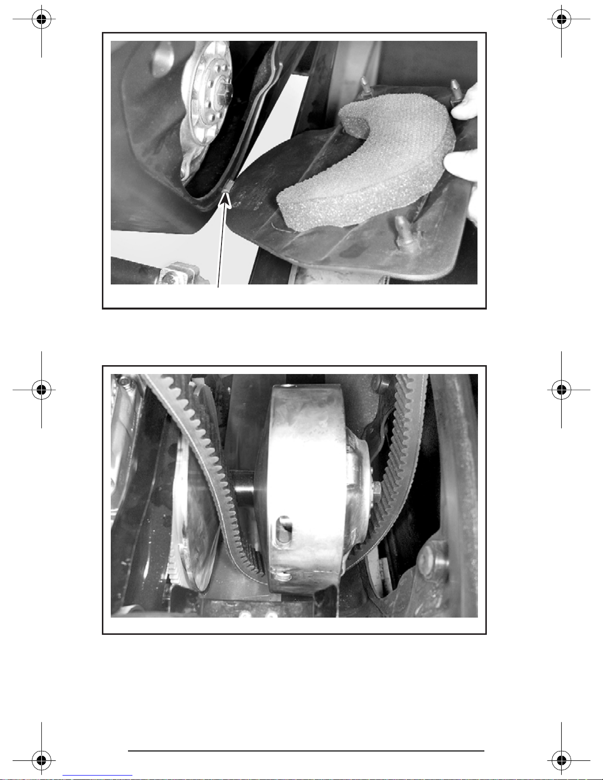
A30C05A
1. Pull panel tab out of bottom pan
1
Slip belt under drive pulley then, remove it from vehicle.
A30D0CA
Clean sheaves of both pulleys using BOMBARDIER Parts Cleaner
(P/N 413 711 809).
86
Page 89
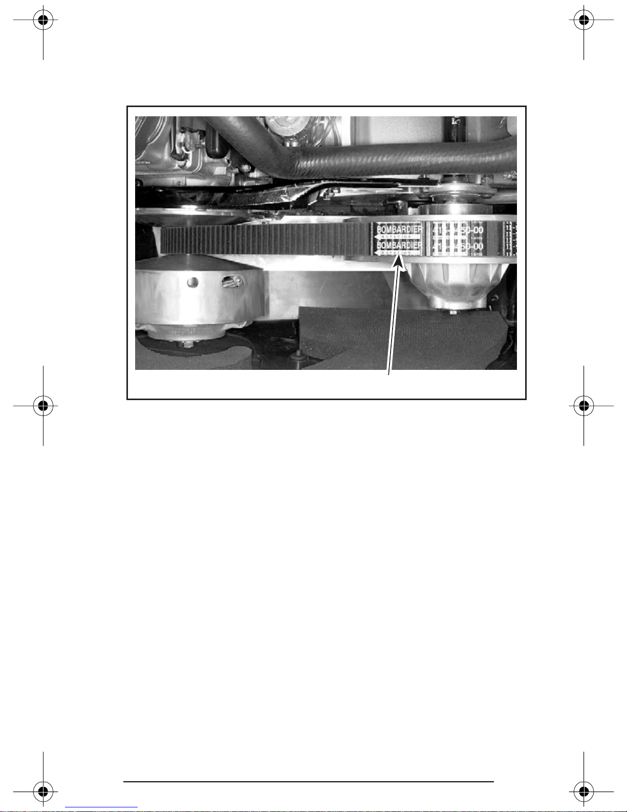
To install the drive belt, reverse the removal procedure, however pay
attention to the following:
The maximum drive belt life span is obtained when the belt has the
proper rotation direction. See arrow on belt.
A30D0DA
1. Arrow pointing front of vehicle
1
CAUTION: Do not force or use tools to pry the belt into place, as
this could cut or break the cords in the belt.
To install the drive belt, first place belt between drive pulley sheaves.
Then, between driven pulley sheaves, finishing with bottom.
Remove drive belt installer/remover. Reinstall access panel and belt
guard.
87
Page 90
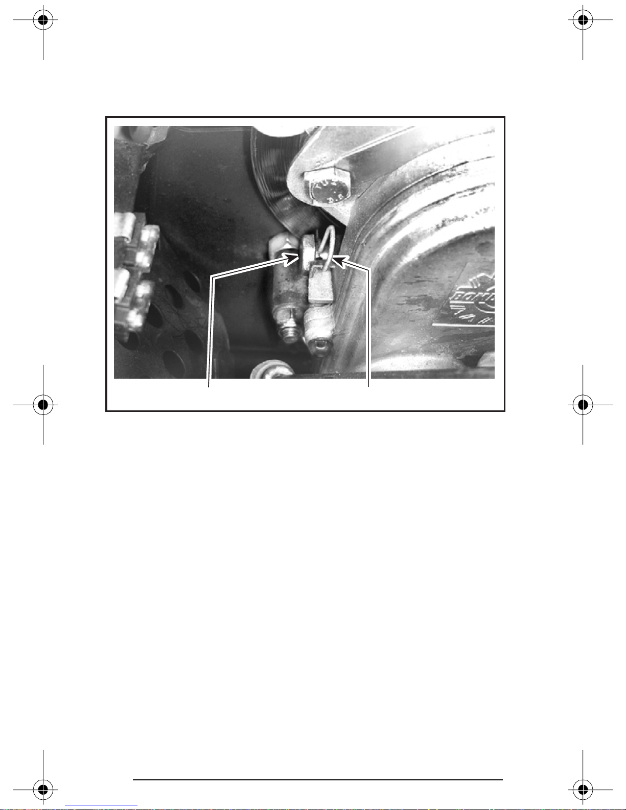
Drive Chain Tension
Remove hair pin.
Fully tighten tensioner adjustment screw by hand, then back off only
far enough for hair pin to engage in locking hole.
A30D0EA
1. Hair pin
2. Adjustment screw
2
1
TRA Drive Pulley Adjustment
The drive pulley is factory calibrated to transmit maximum engine
power at a predefined RPM. Refer to SPECIFICATIONS at the end of
this guide. Factors such as ambient temperature, altitude or surface
condition may vary this critical engine RPM thus affecting snowmobile efficiency.
This adjustable drive pulley allows setting maximum engine RPM in
the vehicle to maintain maximum power.
Calibration screws should be adjusted so that actual maximum engine RPM in vehicle matches with the maximum horsepower RPM.
NOTE: Use precision digital tachometer for engine RPM adjustment.
NOTE: The adjustment has an effect on high RPM only.
88
Page 91
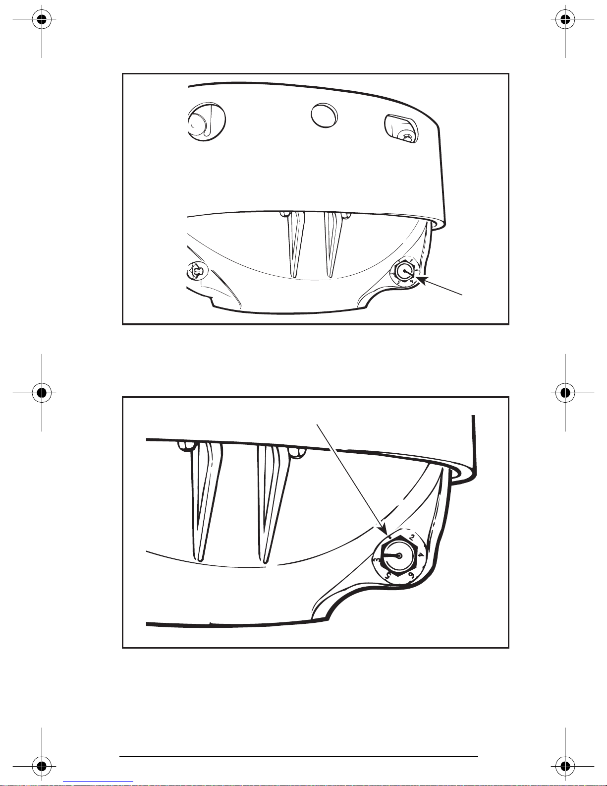
To adjust, turn calibration screws.
Calibration screw has a notch on top of its head.
A16D0FA
1
1. Notch
Governor cup has 6 positions numbered 2 to 6. Note that in position 1
the number is substitued by a dot (due to its location on casting).
1
A16D0GA
1. Position 1 (not numbered)
Each number modifies maximum engine RPM by about 200 RPM.
89
Page 92
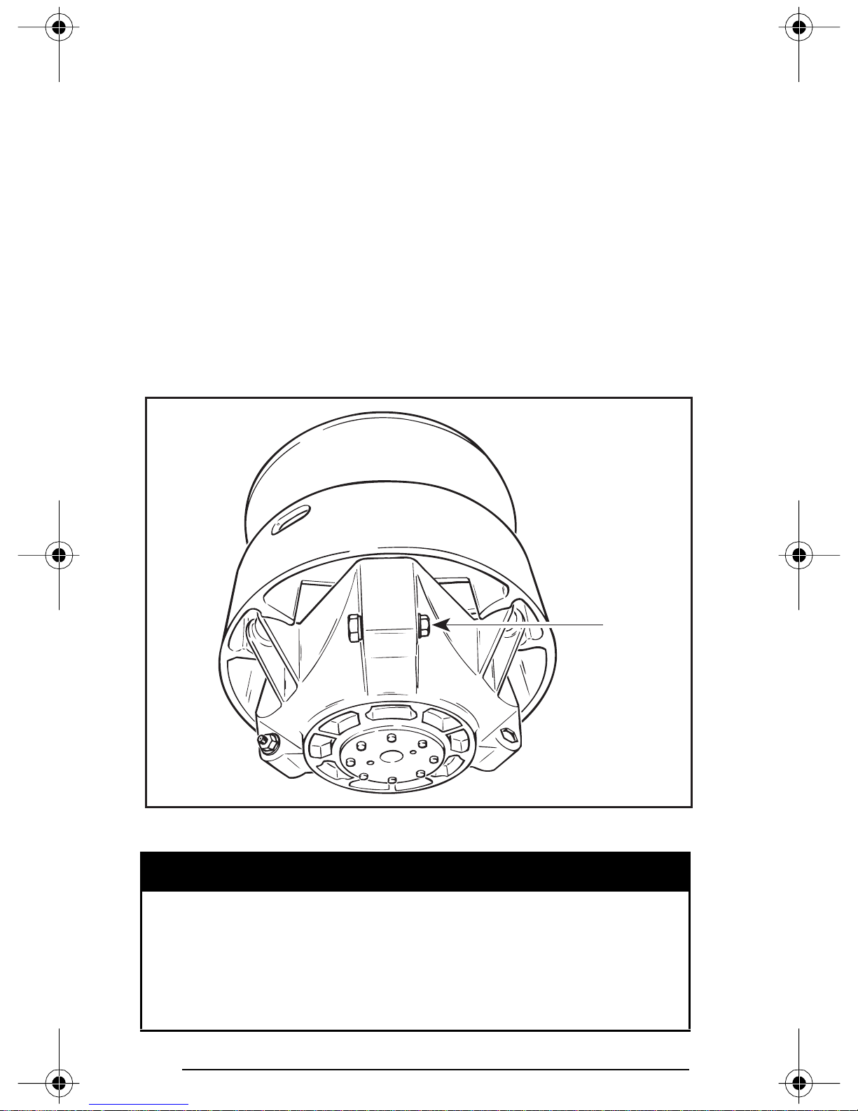
Lower numbers decrease engine RPM in steps of 200 RPM and higher numbers increase it in steps of 200 RPM.
Example:
Calibration screw is set at position 4 and is changed to position 6. So
maximum engine RPM is increased by 400 RPM.
CAUTION: Do not adjust TRA drive pulley so that engine turns
over maximum power RPM. Refer to SPECIFICATIONS.
To adjust:
Just loosen locking nut enough to push calibration screw partially
out and adjust to desired position. Do not completely remove the
locking nut. Torque locking nuts to 10 N•m (89 lbf•in).
CAUTION: Do not completely remove calibration screw or its inside washer will fall off. Always adjust all 3 calibration screws
and make sure they are all set at the same number.
1
A16D0HA
1. Loosen just enough to permit rotating of calibrate screw
WARNING
Always reinstall belt guard. Do not operate engine with hood
open or belt guard removed. Improper servicing, modification
or poor adjustment may affect drive pulley performance and
belt life. Always refer to the Shop Manual or obtain SKI-DOO
dealer advice before servicing or modifying the drive or driven
pulleys. Always respect maintenance schedules.
90
Page 93

Drive Belt Condition
Inspect belt for cracks, fraying or abnormal wear (uneven wear, wear
on one side, missing cogs, cracked fabric). If abnormal wear is noted,
probable cause could be pulley misalignment, excessive RPM with
frozen track, fast starts without warm-up period, burred or rusty
sheave, oil on belt or distorted belt. Contact an authorized SKI-DOO
dealer.
Check the drive belt width. Replace the drive belt if width is less than
the minimum width recommended in SPECIFICATIONS.
Brake Condition
WARNING
The brake mechanism on your snowmobile is an essential
safety device. Keep this mechanism in proper working condition. Above all, do not operate the snowmobile without an
effective brake system. Periodically verify the condition/wear
of the brake pads.
Brake Adjustment
A hydraulic brake is not adjustable. See an authorized SKI-DOO dealer
if any problems.
Rear Suspension Condition
Visually inspect all suspension components including slider shoes,
springs, wheels, etc.
NOTE: During normal driving, snow will act as a lubricant and coolant
for the slider shoes. Extensive riding on ice or sanded snow, will
create excessive heat build-up and cause premature slider shoe wear.
Suspension Stopper Strap Condition
Inspect stopper strap for wear and cracks, bolt and nut for tightness.
If loose inspect holes for deformation. Replace as required. Torque nut
to 9 N•m (80 lbf•in).
Track Condition
Lift the rear of the snowmobile and support it off the ground. With
the engine off, rotate the track by hand, and inspect condition. If worn
or cut, or if track fibers are exposed, or if missing or defective inserts
or guides are noted; contact an authorized SKI-DOO dealer.
91
Page 94
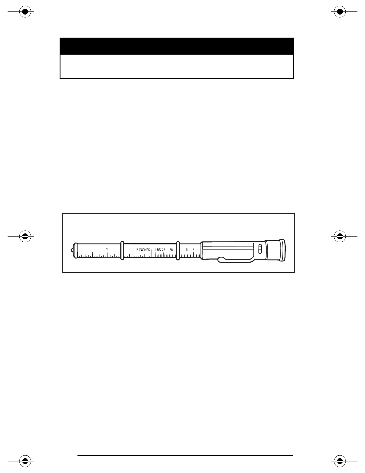
Do not modify track, including by installing traction enhancing products. This may weaken the track and cause it to break without warning.
WARNING
Do not operate or rotate a track if torn, damaged or excessively
worn.
Track Tension and Alignment
Tens io n
NOTE: Ride the snowmobile in snow about 15 to 20 minutes prior to
adjusting track tension.
Lift rear of snowmobile and support it with a snowmobile mechan-
ical stand.
Allow the suspension to extend normally and check gap half-way
along slider shoe. The gap should be as given in SPECIFICATIONS.
If the track tension is too loose, track will have a tendency to thump.
NOTE: A belt tension tester (P/N 414 348 200) may be used to measure deflection as well as force applied.
A00C07A
1. Belt tension tester
1
92
Page 95
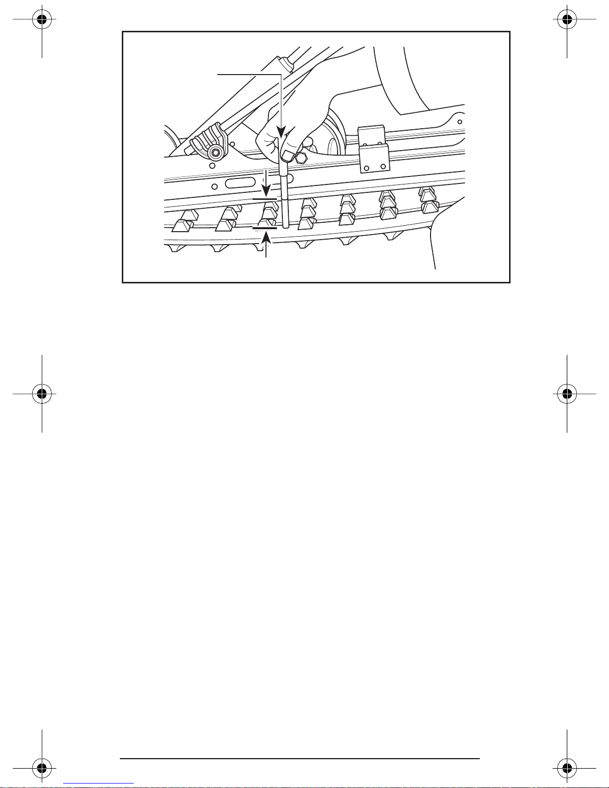
1
A06F1WA
TYPICAL
1. 7.3 kg (16 lb)
2. Deflection
2
CAUTION: Too much tension will result in power loss and excessive stresses on suspension components.
To adjust tension:
– Remove wheel cap.
– Loosen the rear idler wheel retaining screws.
– Turn adjustment screws to adjust.
If correct tension is unattainable, contact an authorized SKI-DOO dealer.
93
Page 96
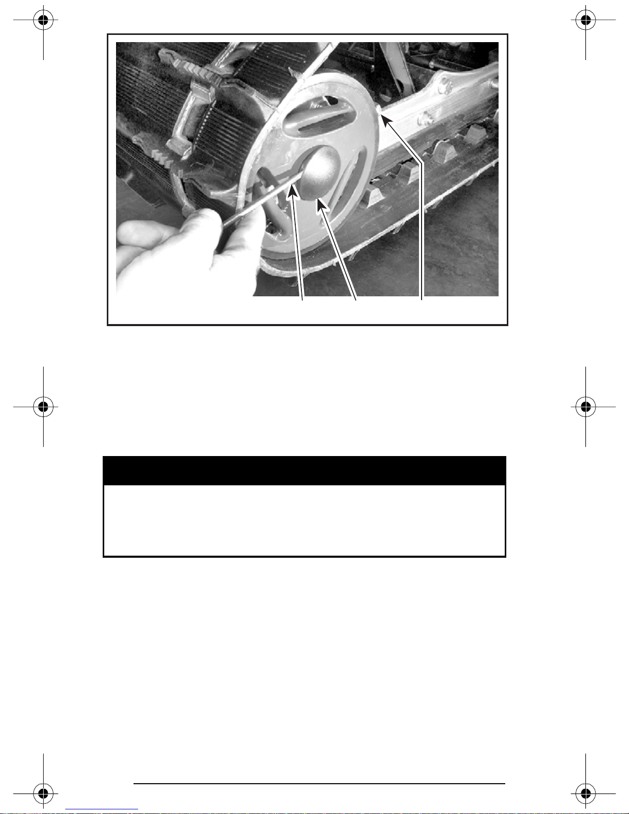
A30F03A
TYPICAL
1. Adjustment screw
2. Loosen screw
3. Wheel cap removing
Alignment
NOTE: Track tension and alignment are inter-related. Do not adjust one
without the other.
WARNING
Before checking track alignment, ensure that the track is free
of all particles which could be thrown out while track is rotating. Keep hands, tools, feet and clothing clear of track. Ensure
no one is standing in close proximity to the snowmobile.
123
94
Page 97
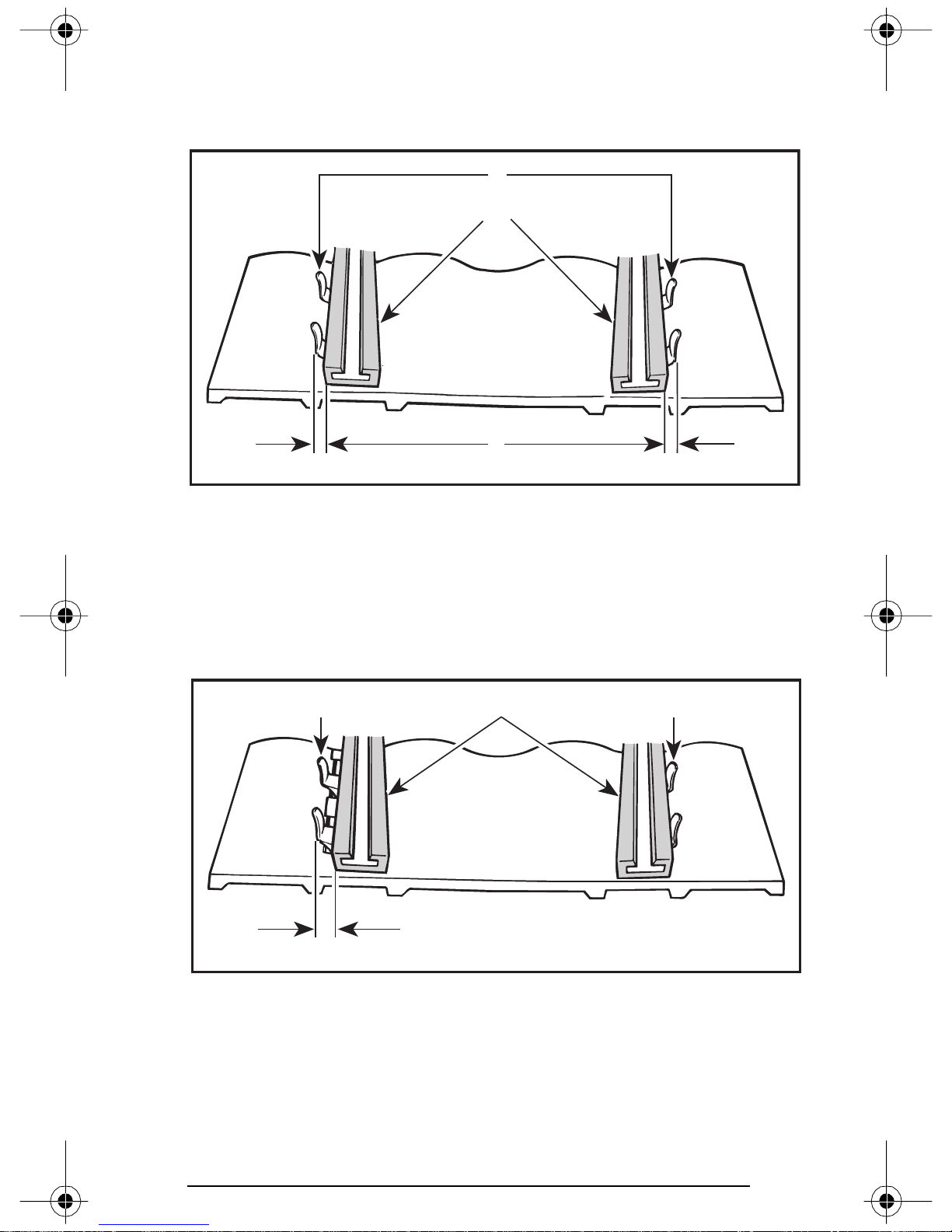
Start the engine and accelerate slightly so that track barely turns. This
must be done in a short period of time (1 to 2 minutes). Check that
the track is well centered; equal distance on both sides between
edges of track guides and slider shoes.
1
2
3
A01F05A
TYPICAL
1. Guides
2. Slider shoes
3. Equal distance
To correct, stop the engine: Loosen rear wheel screws tighten the
adjustment screw on side where the slider shoe is the farthest from
the track insert guides.
1
2
1
3
A01F0BA
TYPICAL
1. Guides
2. Slider shoes
3. Tighten on this side
95
Page 98
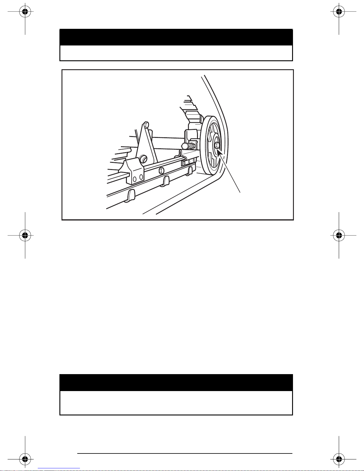
Retighten wheel screws to 48 N•m (35 lbf•ft).
WARNING
Properly tighten wheel screws, otherwise the track will “lock”.
1
A05F0EC
TYPICAL
1. Retighten to 48 N•m (35 lbf•ft)
Restart engine and rotate track slowly to recheck alignment.
Reposition snowmobile on ground.
Steering and Front Suspension Mechanism
Visually inspect steering and front suspension mechanism for tightness of components (steering arms, control arms and links, tie rods,
ball joints, ski coupler bolts, etc.). If necessary, contact your SKI-DOO
dealer.
Wear and Condition of Skis and Runners
Check the condition of the skis, ski runners and ski runner carbides.
If worn, contact your authorized SKI-DOO dealer for replacement.
Excessively worn skis and/or ski runners will affect snowmobile control.
96
WARNING
Page 99
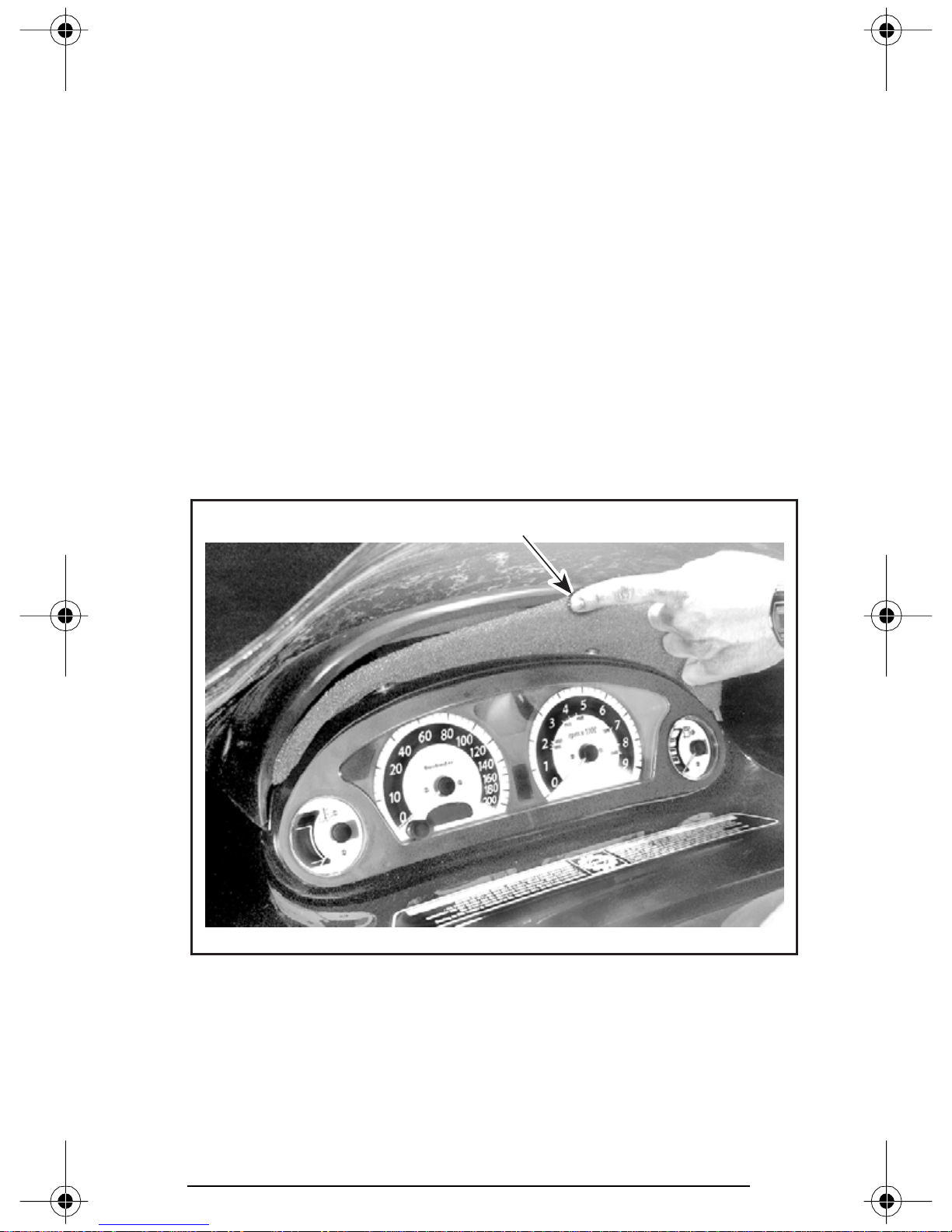
Exhaust System
The tail pipes of the muffler should be centered with the exit holes
in the bottom pan. Exhaust system must be free of rust or leaks.
Make sure that gear clamps are properly tightened.
The exhaust system is designed to reduce noise and to improve the
total performance of the engine. Modification may be in violation of
local laws.
CAUTION: If any exhaust system component is removed, modified or damaged, severe engine damage may result.
Air Filter Cleaning
Leaving the snowmobile uncovered during a snowfall or riding in
deep powder snow may block air filter and choke the engine.
While riding in deep powder snow, periodically stop then shake the
snow from the filter and reinstall filter.
Insert air filter so its top edge is flush with air deflector.
A30H0RA
TYPICAL
1. Top edge of filter flush with air deflector
1
97
Page 100
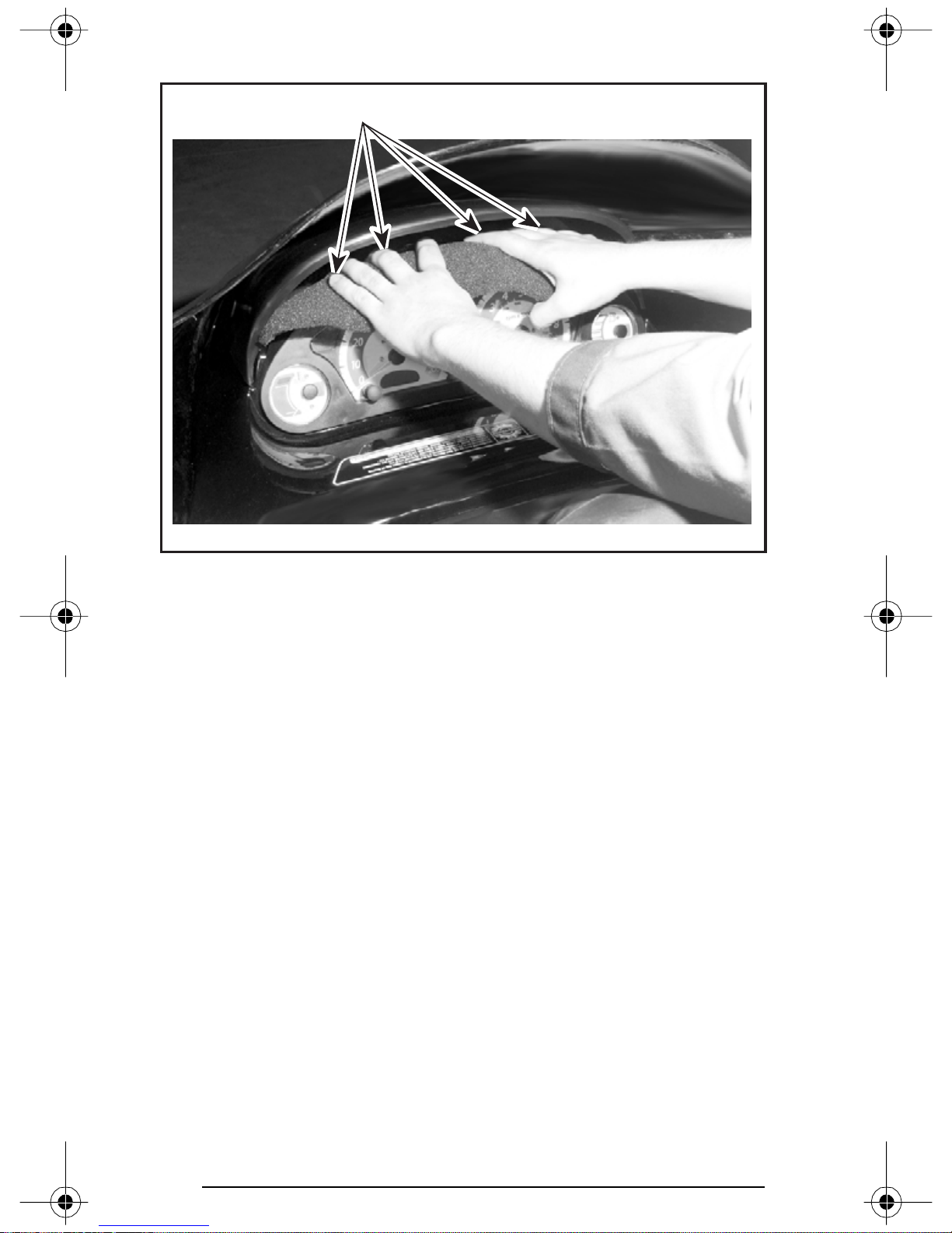
Reinstall filter over dashboard sticking bottom edge first.
1
A30H0SA
TYPICAL
1. Stick bottom edge first
Finalize filter top edge installation.
98
 Loading...