

Page 1
User Guide
skeye.dart
HW 90240
Version 1.04
Page 2

This document and its contents shall not be reproduced or transferred in any form without
express permission. Compensation will be claimed for any infringement. All rights reserved in
the event of patenting or registration of utility models.
© Höft & Wessel AG 2009
Subject to amendment, errors excepted
BHB_skeye-dart_HW90240_1-04_EN.doc
Page 3

TABLE OF CONTENTS
19.05.2010 • 1.04 3
Table of contents
1. Introduction ................................................................................................. 5
1.1 Document Information ............................................................................... 5
1.2 Changes ................................................................................................... 5
1.3 Terminology .............................................................................................. 5
1.4 Readership................................................................................................ 6
1.5 Intended Use ............................................................................................ 6
1.6 Safety Notes ............................................................................................. 6
1.6.1 General Safety Notes ........................................................................... 6
1.6.2 Safety Notes for the Lithium-Ion Battery................................................. 7
1.6.3 Safety Notes for the Communication Cradle/ Battery Charger ...................11
1.6.4 Safety Notes for the Power Supply ........................................................11
1.6.5 Safety Notes on the Camera/Imager with LED Aimer (optional) ................12
1.6.6 Safety Notes on GSM/GPRS/EDGE (optional) ..........................................12
1.6.7 Safety Notes on Wireless LAN/Bluetooth ................................................13
1.6.8 Safety Notes on Data Loss ...................................................................13
1.7 Disposal ..................................................................................................13
1.8 Explanations on this Manual .......................................................................14
1.8.1 Note Pictograms .................................................................................14
1.8.2 Registered Trademark .........................................................................15
2. skeye.dart................................................................................................... 16
2.1 Variants of the Base Types.........................................................................16
2.2 Accessories ..............................................................................................17
2.3 Communication Cradle ..............................................................................17
2.4 Hardware Equipment.................................................................................17
2.5 Software Equipment ..................................................................................17
2.6 Views ......................................................................................................18
2.6.1 Front View .........................................................................................18
2.6.2 Side View...........................................................................................19
2.6.3 Rear View ..........................................................................................19
2.7 LED Function Displays ...............................................................................19
3. Taking into Operation ................................................................................. 20
3.1 Switching on the Backup Battery ................................................................20
3.2 Inserting the Micro SD Card .......................................................................21
3.3 Insertions of the SIM Card .........................................................................22
3.4 Battery ....................................................................................................23
3.4.1 Inserting the Battery ...........................................................................23
3.4.2 Replacing the Battery ..........................................................................24
3.4.3 Charging the Battery ...........................................................................24
3.5 Switching On/Switching Off the skeye.dart...................................................25
3.5.1 Switching On......................................................................................25
3.5.2 Switching Off the skeye.dart ................................................................25
3.5.2.1 Suspend Mode ..............................................................................25
3.5.2.2 Automatic Standby – Power Supply .................................................27
3.5.2.3 Complete Power Off by Removing the Battery ...................................28
4. Initial Steps ................................................................................................ 29
4.1 Operating the skeye.dart with the Stylus .....................................................29
4.2 Microsoft Windows CE – Basics ...................................................................30
4.2.1 Start Screen.......................................................................................30
4.2.2 Start Menu.........................................................................................30
4.2.3 Desktop Symbols ................................................................................31
4.2.4 Taskbar .............................................................................................31
4.2.5 Right Mouse Button Function ................................................................32
4.2.6 Showing/Hiding the Keyboard...............................................................32
Page 4

TABLE OF CONTENTS
4 1.04 • 19.05.2010
4.2.7 Basic Settings.....................................................................................32
4.2.7.1 Calibrating the Touch Screen ..........................................................33
4.2.7.2 Setting the Brightness ...................................................................35
5. Further Functions and Settings................................................................... 36
5.1 Setting of Display Orientation and -Dissolution .............................................36
5.2 Scan of Barcodes ......................................................................................36
5.3 Scan Keys................................................................................................37
5.4 SysAP......................................................................................................37
5.5 Soundset .................................................................................................38
5.6 System Info .............................................................................................39
5.7 SysBackup ...............................................................................................40
5.7.1 Calling SysBackup...............................................................................41
5.7.2 Creating a Backup...............................................................................42
5.7.3 Restoring the Backup ..........................................................................43
5.7.4 Deleting a Backup ...............................................................................44
6. Radio .......................................................................................................... 45
6.1 Wireless LAN ............................................................................................45
6.1.1 Wireless LAN Network Settings .............................................................45
6.1.2 Wireless LAN Configuration ..................................................................46
6.1.3 Entering the Network ID ......................................................................48
6.2 GSM Control.............................................................................................49
6.2.1 Establishing a Connection ....................................................................49
6.2.2 Further Settings .................................................................................51
6.2.2.1 Persistent Setting of the PIN Number...............................................51
6.2.2.2 General Settings ...........................................................................52
6.2.2.3 APN .............................................................................................53
6.2.2.4 GSM Info......................................................................................53
6.3 GPS Module .............................................................................................54
7. Communication Cradles .............................................................................. 55
7.1 Communucation Cradle (USB Standard) ......................................................55
7.2 Technical Data..........................................................................................55
7.3 Charging the Battery in the Communication Cradle .......................................56
7.4 Connecting the Communication Cradle to the Desktop PC ..............................56
7.5 Desktop Cradle (USB with Battery Charger) .................................................57
7.6 Technical Data..........................................................................................57
7.7 Charging the Battery in the battery charger slot ...........................................58
7.8
Communication skeye.dart ⇔ PC ................................................................59
7.9 Application of USB Host .............................................................................60
8. Technical Data ............................................................................................ 61
9. Troubleshooting.......................................................................................... 62
9.1 Reset via Software ....................................................................................62
9.2 Reset via Hardware ...................................................................................62
Page 5

INTRODUCTION
Document Information
19.05.2010 • 1.04 5
1. Introduction
The skeye.dart is a modern industrial PDA. It has been designed for the use as
selfscanning terminal or mobile terminal for field applications. You can choose
between several variants.
With protection level IP54 against dust and moisture and drop protection of 1.20 m
the skeye.dart is proper for the use in rough environments.
1.1 Document Information
Product: skeye.dart
Type of Document: User Guide
Version: 1.04
Author: Lin / Höft & Wessel AG, Hannover
1.2 Changes
Version: Changes: Date: By:
01.00 First version 09.01.2009 Lin
01.01 Hint backup battery clarified 21.04.2009
Lin
01.02 Adjusted to current techn. status/edited 18.05.2009
Esp/Lin
01.03 New chapters: Insertion of the SIM card; GSM
service; Establishing a GPRS connection; SysApp;
SysBackup; Soundset; GPS module Revision
16.11.2009
Lin
01.04 Enhanced by keye.dart PBV and XKE Lin
1.3 Terminology
skeye.dart
HW 90240
Portable Data Terminal (in the following referred as “mobile
terminal”) with WLAN IEEE 802.11b/g and Bluetooth 2.0
skeye.dart FFE
HW 90240 FFE
Like the skeye.dart, additionally with GSM/GPRS/EDGE and
GPS
skeye.dart PBV
HW 90240 PBV
Like the skeye.dart, additionally with headset connection
("Pick-by-Voice")
skeye.dart XKE
HW 90241 XKE
Like the skeye.dart, additionally with 31 key keyboard
("Extended Keyboard Edition")
Battery HW 19240 The mobile terminal is supplied by a rechargeable lithium-
ion battery
Communication cradle USB
HW 50240
Communication cradle with USB interface for the mobile
terminal (Standard)
Desktop cradle USB
HW 50242
Communication cradle with USB interface for the mobile
terminal (with additional battery charging compartment)
Power supply unit Wide range switched mode power supply unit to provide the
mobile terminal and the communication cradle with power.
Passive holder HW 51240 For installation of the skeye.dart in vehicles and for charging
of the battery.
Page 6

INTRODUCTION
Readership
6 1.04 • 19.05.2010
1.4 Readership
The documentation is intended for people operating the skeye.dart.
1.5 Intended Use
The skeye.dart has been designed for use in the commercial sector and for
acquiring and transferring data within buildings or vehicles or outside under
moderate climate conditions.
The skeye.dart is not intended for distribution to private households.
Please pay attention to the information of this user guide, especially the safety
notes. Intended use means that the device must only be used and operated in
accordance with the information contained herein. Any other use is not an intended
use and may lead to property damage or even personal injury. Höft & Wessel does
not accept any liability for damages caused by a usage other than the intended
usage.
1.6 Safety Notes
Carefully read and follow the user manual and the safety information mentioned in
this chapter before performing further steps. You have to:
• read
• keep the information in mind during work.
This is the precondition for
• secure working with the product
• undisturbed handling
1.6.1 General Safety Notes
Transport and Storage:
♦ The device must only be shipped in original or comparable robust packaging.
Shipping the device e.g. in a normal padded bag does not provide sufficient impact
and pressure protection.
Such improper packaging would fall under the definition of the term Negligence.
Handling:
♦ Never expose the skeye.dart to very high temperatures for a long time.
♦ Never insert any objects not intended for use with this device in the instrument’s
openings. This might damage the device.
Operating:
♦ Do not dip the skeye.dart into fluid.
♦ Only use your skeye.dart with original equipment. Non-compliance voids the
warranty.
♦ Do not operate your skeye.dart when you are in explosive areas, for instance in
petrol stations, fuel depots, chemical plants, below deck in ships, near blasting
operations, in locations where a large volume of dust particles (such as flour, wood
or metal) is present in the air, etc.
Page 7
INTRODUCTION
Safety Notes
19.05.2010 • 1.04 7
We recommend to switch off the device completely. This also applies to places
where you are usually advised to switch off your vehicle motor.
♦ Do not operate in close range of strong electromagnetic fields. Failures may be
caused.
♦ Interference may be noticed near electric devices. Therefore, always pay attention
to local safety regulations.
♦ Users with hearings aids must note that radio signals of electronic devices (with
radio equipment) may launch into hearing devices causing an unpleasant noise.
Maintenance, Service and disturbances:
♦ The skeye.dart is – apart from charging of battery and the mentioned comments –
lifetime maintenance-free and does not need special care.
♦ Do not try to open, repair or modify your skeye.dart. The manufacturer will not be
liable for any damage caused in that way. Apart from other things, the function for
correctly charging the battery may be influenced. As a result, excessive charging
voltage, uncontrolled charging and discharge current, leakage of harmful
substances, excessive heat generation, bursting or fire may occur.
♦ Any tampering by non-authorised persons will invalidate the warranty.
♦ If your skeye.dart needs to be repaired or maintained, please contact your
specialised dealer.
♦ Clean the housing only with damp cloth and mild detergent.
1.6.2 Safety Notes for the Lithium-Ion Battery
Carefully read the following safety notes to prevent an incorrect handling of the
battery and to avoid possible dangers.
Non-observance of the safety information or incorrect use of the battery
can lead to excessive current flow, to the discharge of harmful substances,
excessive heat development, explosion or fire.
Transportation and storage:
♦ Do not transport or store the battery together with metal objects such as necklaces,
hairpins, etc. Doing so may short circuit the battery, which could result in excessive
current flow and possibly cause leakage of battery fluid, heat generation, bursting
or fire. When carrying or storing batteries, use an electrically nonconductive
(insulated) case.
♦ When the equipment is expected not to be used for a long time do not store the
batteries exceeding the appropriate conditions as listed below. Otherwise its
performance will be degraded and its service life will be decreased.
▪ when the batteries are discharged and remain in the equipment: 1 week
▪ when the batteries are fully charged and remain in the switched off
equipment: 1 month
▪ long-term storage: see next note.
♦ When the battery is expected not to be used for a long time, take the battery out of
the equipment and store it in a dry place at or below room temperature. For an
optimum service life, the battery should be charged up to 20 to 40% when being
stored. After 12 months at the latest the device should be charged and
subsequently discharged. Otherwise, its performance will be degenerate and its
service life will be decreased.
Page 8

INTRODUCTION
Safety Notes
8 1.04 • 19.05.2010
♦ Switch off the backup battery if you do not use the device for a longer time (see
chapter 3.1)
♦ Store the battery in a location where children cannot reach it. Also make sure that a
child does not take out the battery from the charger or equipment being used. If a
child swallows a battery, seek medical attention immediately.
♦ The storage temperature must not be below –20 or above +50°C.
Ambient conditions:
♦ The temperature may not be outside the admissible operating and storage
temperature range of -20 to +50 degrees centigrade. The temperature may be
within the range of 0 °C to +40 °C during charging.
♦ Do not discard the battery into fire and do not leave it in a hot place such as near a
fire or on a heater. Doing so melt the insulation, damage the sealing parts or
protective devices, cause leakage of battery fluid (Electrolyte) from the batteries,
bursting or fire.
♦ Do not immerse batteries in water or seawater, and do not allow them to become
wet. Batteries which have become wet must always be replaced with new ones
because internal short-circuits can cause dangerous heat emissions if further used.
♦ Do not throw batteries, and do not allow them to fall on hard surfaces.
Connection:
♦ Do not connect the battery to an electrical outlet, e.g. vehicle cigarette lighter,
power outlets, other power supply units, other charger, etc.
♦ Do not reverse the positive (+) and negative (-) terminals when inserting the
battery. Since the mechanical design of the battery enables you to insert in one
direction only, the battery must not be inserted into the opposite direction by force.
Handling:
♦ Protective devices to prevent danger are built into the battery. To ensure for a
proper operation, do not disassemble the battery or modify parts of it. If they are
damaged, this could result in excessive charging voltage, control loss during
charging or discharging, leakage of battery fluid, heat generation, bursting or fire.
♦ Do not disassemble Li-ion bare cells of the battery. There is the danger of flammable
fluid being spilt. It may also cause an internal or external short circuit, leakage of
battery fluid, heat generation, bursting or fire.
♦ Do not directly solder the battery. Doing so melt the insulation, damage the sealing
parts or protective devices, cause leakage of battery fluid (Electrolyte) from the
batteries, bursting or fire.
♦ Do not short-circuit the battery by directly connecting the positive (+) and negative
(-) terminals with objects such as wire. Short circuiting generates heat which may
damage the equipment. In the worst case this could result in leakage of battery
fluid, bursting or fire.
♦ Do not put the battery into a microwave oven or pressurised container. This could
result in leakage of battery fluid, bursting or fire.
♦ Do not pierce the battery with a nail or other sharp object, hit it with a hammer, or
step on it. This could result in leakage of battery fluid, bursting or fire.
Page 9

INTRODUCTION
Safety Notes
19.05.2010 • 1.04 9
Operation:
♦ For operation of the device use the delivered battery only. Please use the battery
only for the determined purpose.
♦ Do not use the battery in any device other than those specified in this manual.
Depending on the device being used, doing so may cause abnormal current flow,
leakage of battery fluid, heat generation, bursting or fire.
♦ If the battery becomes discolored or deformed, or in any way appears abnormal,
stop using it. Return it to the distributor or manufacturer from whom you purchased
it.
♦ Do not use or leave the battery in very high temperatures (for example, under
strong direct sunlight). Otherwise, it may cause leakage of battery fluid, bursting or
fire or its performance will be degenerate and its service life will be decreased.
♦ To ensure safety, the battery incorporates built-in safety devices. Do not use it in a
location where static electricity is greater than what the manufacturer guarantees.
Otherwise, the safety devices may be damaged, causing leakage of battery fluid,
expose of fire.
♦ Do not use the battery in other than the following conditions. Otherwise, it can
overheat or fire, or its performance will be degenerate and its service life will be
decreased.
▪ when the battery is charged: 0 °C ~ +40 °C
▪ when the battery is discharged or stored: -10 °C ~ +50 °C
Note: higher temperatures increase the self-discharge of the battery.
♦ Do not use the battery in combination with primary batteries (such as dry-cell
batteries) or batteries of different capacities or brands. That may cause leakage of
battery fluid, heat generation, bursting or fire.
♦ Do not connect different assembled batteries together. And also do not connect
same assembled batteries in series, unless explicitly instructed by the user
information to do so.
Charging:
♦ When recharging, only use the battery charger specially provided by Skeye. Failure
to follow proper charging procedures may cause excessive voltage, excessive
current flow, loss of control during charging, leakage of battery fluid, heat
generation, bursting, or fire.
♦ Do not use or charge the battery near a heat source such as fire or heater or in
extremely hot weather.
♦ Do not charge a battery when it is cold (below 0 °C). This may cause impaired
performance and shortening of battery service life.
♦ If a battery is to be used for the first time or it has not been used for a long time,
be sure to charge it.
Page 10

INTRODUCTION
Safety Notes
10 1.04 • 19.05.2010
Health hazards:
♦ If a battery leaks, and the electrolyte enters the eye, do not rub but rinse out
thoroughly under flowing water and then seek medical assistance. Otherwise, eye
damage can result.
♦ If a battery leaks and the electrolyte makes contact with clothing or the skin, the
skin or clothing must be rinsed out under flowing water in order to prevent damage
to the skin.
Maintenance, service and disturbances:
♦ Lithium-ion batteries have a predetermined operating life. If the operating time
shortens excessively, this means that the battery life has expired. If it comes to
that point, stop use immediately and replace with new batteries.
♦ Lithium-ion battery is a designated product of Recycle. The battery after using is a
valuable resource. The return of the batteries ensures reuse of the chemicals
contained. This recycling process avoids any impact to the environment.
Höft & Wessel guarantees that all batteries returned are fed to the recycling
process.
When a battery is no longer usable, discharge it. When you dispose of the Lithium
battery, insulate it by wrapping the terminals with tape. Mixing the battery with
other metals or batteries may lead to fire, heat, or explosion.
Then, return the battery to Höft & Wessel. As a part of its normal service,
Höft & Wessel guarantees that all used batteries are fed to the recycling process.
See also extract from BattV (Decree for the return and disposal of used batteries
and accumulators, Germany) as of 09.09.2001:
„The manufacturers are obliged to take back and reuse toxic containing
batteries according to the regulations and dispose of non-reusable batteries that
have been handed in by distributors (§5) or public disposal departments (§9).“
♦ If Lithium-ion batteries are not fully charged after the battery charger’s
predetermined charging period has elapsed, stop the charging process. Prolonged
charging may cause leakage of battery fluid, heat generation or bursting of fire.
♦ If the battery leaks or gives off a bad odor, remove it from any exposed flame.
Otherwise, the leaking electrolyte may catch fire, and the battery may explode or
fire.
♦ If the battery gives off an odor, generates heat, becomes discolored or deformed, or
in any way appears abnormal during use, recharching or storage, immediately
remove it from the device or battery charger and stop using it.
♦ In case the battery terminals are dirty, clean the terminals with a dry cloth before
use, otherwise, the contact with equipment may cause insufficiency, and power
failure or charge failure.
Page 11
INTRODUCTION
Safety Notes
19.05.2010 • 1.04 11
1.6.3 Safety Notes for the Communication Cradle/ Battery Charger
♦ The battery may only be charged with the battery charging device recommended by
the manufacturer. The utilisation of another battery charger might be dangerous
and leads to an end of the warranty.
♦ Do not try to open, repair or modify your device. The manufacturer will not be liable
for any damage caused in that way. Apart from other things, the function for
correctly charging the battery may be influenced. As a result, excessive charging
voltage, uncontrolled charging and discharge current, leakage of harmful
substances, excessive heat generation, bursting or fire may occur.
♦ If the communication cradle/battery charger changes shape or colour, generates
heat or in any way appears abnormal stop using it. Return it to the distributor or
manufacturer from whom you purchased the communication cradle/battery charger.
♦ Use the communication cradle/battery charger only with the supplied power supply.
The main voltage must correspond to the technical data mentioned on the power
supply.
♦ Use the communication cradle/battery charger only in dry, closed rooms and not in
direct sunlight, e.g. behind windows.
♦ The device has to be connected to a USB 1.1 or higher interface.
♦ Keep the device out of the reach of small children.
1.6.4 Safety Notes for the Power Supply
♦ Do not try to open and/or repair and/or alter the power supply. The manufacturer
will not be liable for any damage caused in that way.
♦ Always connect the power cable into an easy accessible wall outlet.
♦ Always connect the power cable to the device before plugging it into the wall outlet.
Make sure that you do not insert the power cord into the headset plug by mistake.
♦ Check that the plug is clean before plugging it in.
♦ Do not place any objects on top of the cord.
♦ Do not place the cord near heating equipment.
♦ Do not connect cables other than those specified in this manual. Doing so may
result in fire or improper operation.
♦ Do not use a damaged cord.
♦ Handle the power cord with care. Improper handling may lead to fire or shock.
♦ Avoid excessive bending, twisting, and pulling of the cord.
♦ When disconnecting the power cable, hold the plug firmly. Do not tug on the cord
itself.
♦ Use power supply and power cable only in dry rooms.
Page 12
INTRODUCTION
Safety Notes
12 1.04 • 19.05.2010
1.6.5 Safety Notes on the Camera/Imager with LED Aimer (optional)
If your skeye.dart is equipped with an imager module with integrated LED aimer,
please observe the following notes:
The LED light source is classified as a class 1 LED according to the following
standard: IEC60825-1 ED 1.2:2001.
A class 1 LED is presumed to be safe under reasonably foreseeable conditions of
operation. Even looking directly into the light beam by accident does not do any
harm.
Caution: When changing the settings of the imager/aimer module except for those
described in the user guide the LED radiation may exceed the harmless area of
class 1.
1.6.6 Safety Notes on GSM/GPRS/EDGE (optional)
A GSM/GPRS communication can be realised via CF or PC card. If your device features
such equipment pay attention to the safety notes.
Radio devices (such as GSM) are subject to certain restrictions when used in
proximity to electronic instruments:
When being in an aircraft completely power off your skeye.dart (see chapter
3.5.2.3.). Using the skeye.dart in an aircraft interferes with the electronic
equipment on board and might be dangerous. Please follow the instructions of the
particular airline.
♦ Switch off your skeye.dart in hospitals or similar places to prevent an interference
with medical devices.
♦ Switch off your skeye.dart at places where you are advised to switch off your mobile
phone.
♦ The unit may affect heart pacemakers.
The Federal Office for Radiation Protection recommends a distance of no less than
20 cm between a mobile phone and a heart pacemaker to ensure no interference
takes place. This recommendation is also in line with studies and recommendations
issued by independent institutes.
Users with heart pacemakers must ensure a distance of at least 20 cm between the
skeye.dart and the heart pacemaker.
♦ The unit may affect hearing aids.
♦ Interference may be noticed in close proximity to televisions, radios, PCs.
Page 13

INTRODUCTION
Disposal
19.05.2010 • 1.04 13
1.6.7 Safety Notes on Wireless LAN/Bluetooth
A Wireless LAN- or Bluetooth-communication can be realised using an integrated
module. If your skeye.dart is equipped with a WiFI-/Bluetooth-module, please pay
attention to the safety notes.
Radio facilities – as well as Wireless LAN and Bluetooth - are subject to certain
restrictions during use near electronical devices. In this connection please read the
safety notes of the previous chapter.
Wireless LAN data communication and Bluetooth can be easily intercepted and
recorded. Secure your network against unauthorised intrusion into the WLAN. We
recommend that you consult a specialist (e.g. a system house).
1.6.8 Safety Notes on Data Loss
♦ It is very much recommended that all important data be backed up as durable
hardcopy. It is very much recommended to store all recorded data to flash disk and
to regularly back up the data on an external medium. Given certain conditions, loss
or modification of data can occur in practically any electronic storage system.
Therefore, we do not accept any liability for loss of data or data being otherwise
rendered unusable following incorrect use, repairs, faults, battery problems,
software errors or for any other reason.
We shall not be held liable either directly or indirectly for any financial loss or third
party compensation claims which arise on foot of the use of this product and all and
any of its functions, such as stolen credit card numbers, loss or modification of data,
etc.
1.7 Disposal
The skeye.dart is not intended for use in private households. The device must not
be disposed of via a public waste disposal system. For disposal, return the device to
the Höft & Wessel AG.
Page 14
INTRODUCTION
Explanations on this Manual
14 1.04 • 19.05.2010
1.8 Explanations on this Manual
The User Manual is designed to enable you to get your skeye.dart up and running
quickly and is structured as follows:
♦ Introduction
♦ Taking into operation
♦ Software
♦ Communication/Data exchange
♦ Troubleshooting
♦ Annex
It is assumed that your are familiar with Microsoft Windows 2000, Windows XP,
Vista or Windows 7.
In case of problems refer to the corresponding Microsoft documentation.
The skeye.dart supports the operating system Windows CE 6.0.
1.8.1 Note Pictograms
Safety notes in the text are always illustrated in the same way.
In this manual three different safety notes are used.
NOTE!
A note points out tips on simplified use of the system / device for example by
describing a simplified workflow using a certain tool.
CAUTION!
A CAUTION warning sign points out potential dangers relating to the equipment
(i.e. short circuit) or loss of data.
WARNING!
The WARNING sign draws the user's attention to potential dangers that could
be harmful to the health/life of the user (i.e. electric shock) or seriously
damage the equipment (the equipment could be destroyed).
Indicates an alternative method to complete a task or additional information on a topic.
Page 15

INTRODUCTION
Explanations on this Manual
19.05.2010 • 1.04 15
1.8.2 Registered Trademark
The following terms and names used in this manual are registered trademarks and
products of the corresponding companies:
• Microsoft
®
, Windows®, Windows NT®, WindowsXP, Windows CE®, Windows
CE.NET® and ActiveSync® are registered trademarks of the Microsoft
Corporation, USA.
• Other product and company names may be trademarks of other companies.
All trademarks mentioned and possibly protected by third parties are subjected to
the ownership of the corresponding registered owners.
Page 16
SKEYE.DART
Variants of the Base Types
16 1.04 • 19.05.2010
2. skeye.dart
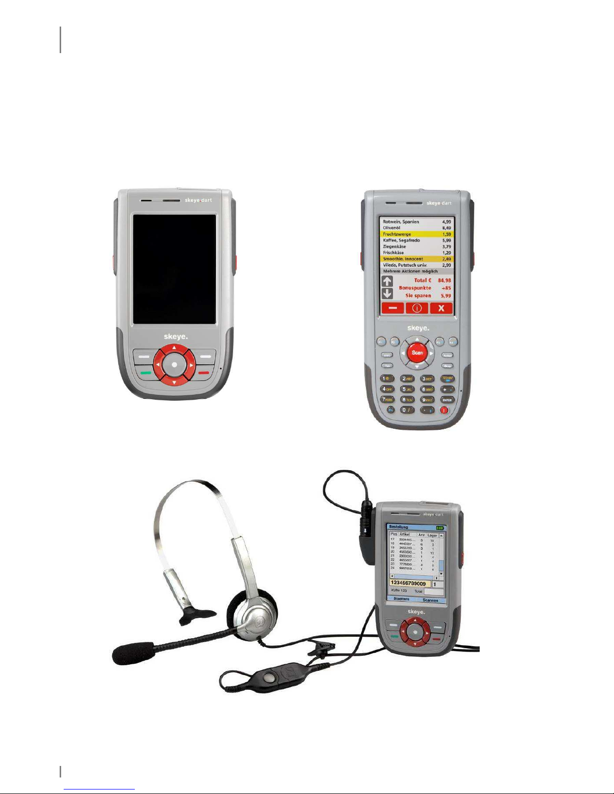
2.1 Variants of the Base Types
There are several different hardware variants available for the skeye.dart. In
contrast to the other variants the FFE variant posseses additional
GSM/GPRS/EDGE- and GPS modules.
Fig. 1: skeye.dart FFE Fig. 2: skeye.dart XKE
Fig. 3: skeye.dart PBV*
*Headset not contained in scope of delivery
Page 17

SKEYE.DART
Accessories
19.05.2010 • 1.04 17
2.2 Accessories
• Battery HW 19240
• Battery HW 19241 (doubled capacity)
• Power supply unit 14240
• Adapter for Sennheiser SH330 Headset
• Case with belt clip
• Stylus
• Display protector
2.3 Communication Cradle
• Communication cradle HW 50240 USB (Standard)
(including power supply unit and USB cable)
• Desktop cradle HW 50242 USB
(including battery charger, power supply and USB-cable)
• Desktop cradle HW 50241 Ethernet
(including battery charger and power supply)
• Car charging cradle HW 51240
(including power cable)
2.4 Hardware Equipment
All variants:
• incl. battery
• 128 MB DDR-RAM, 256 MB Flash
• Integrated Wireless LAN module, 802.11 b/g
• Bluetooth
• SIM card slot (lockable to prevent unauthorised card removal)
• MicroSD card slot (lockable to prevent unauthorised card removal)
skeye.dart:
• ScanCam
• 11 key keyboard
skeye.dart FFE:
• ScanCam
• GPRS
• GPS
• 11 key keyboard
skeye.dart PBV:
• 2D Imager
• Headset-Interface
• 11 key keyboard
skeye.dart XKE:
• ScanCam
• 31 key keyboard
2.5 Software Equipment
Windows Embedded CE 6.0
Page 18
SKEYE.DART
Views
18 1.04 • 19.05.2010
2.6 Views
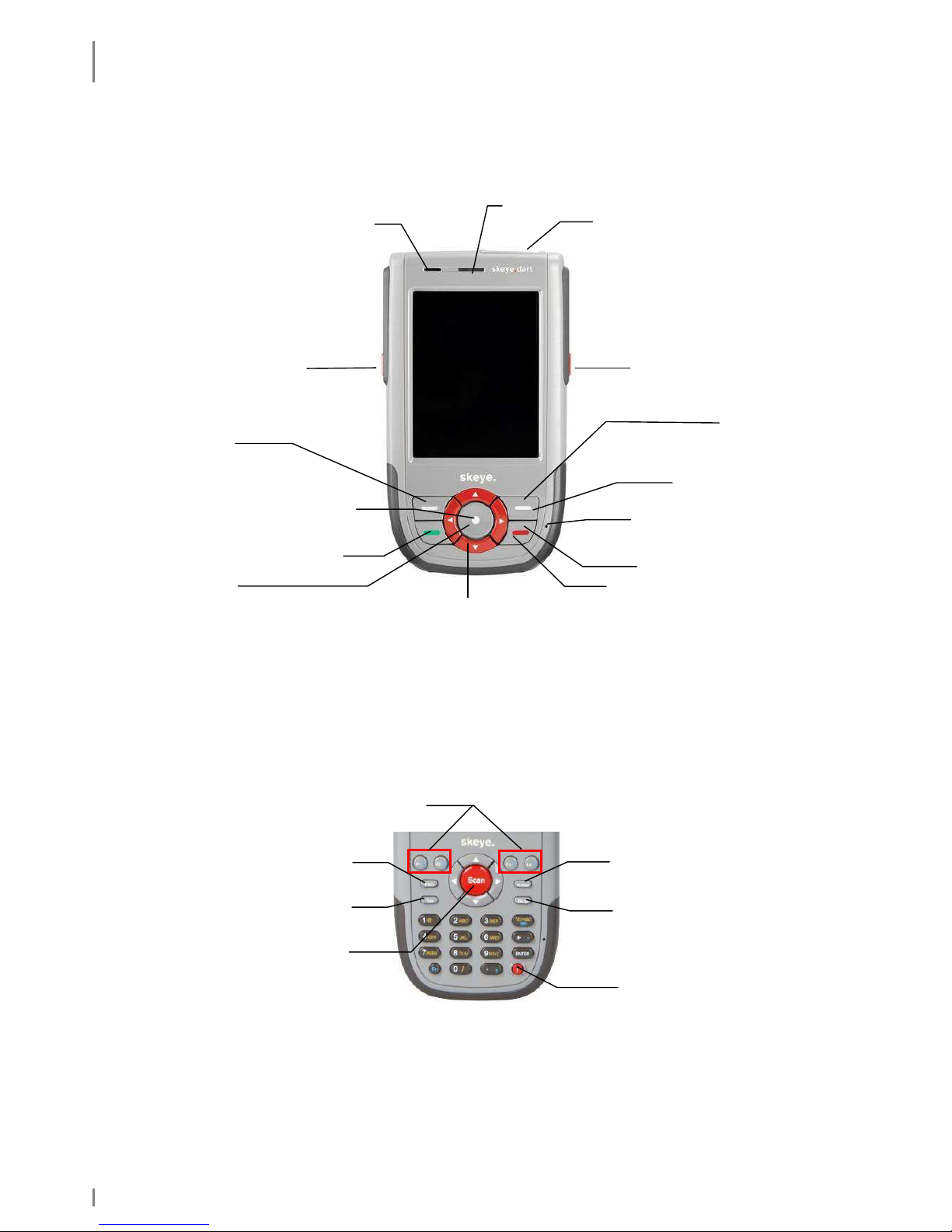
2.6.1 Front View
Fig. 4: Front view
This figure shows the standard keypad assignment for a 5-key-device.
The standard keypad assignment (software) can be optionally changed for all variants.
Keypad assignment for the XKE device
This figure shows the standard keypad assignment for the XKE device.
Fig. 5: Keypad assignment XKE
[Fn] + [
] = show Sip keypad
123>abc = switch between numerical and alphanumerical (yellow) keypad
Loud speaker
LEDs
Imager/Camera
Scanner key
Scanner key
Enter key
Function key 1
In Bootloader:
Enter key
Esc key
Microphone
Standby
(press about 5 s)
Cursor keys
Function key 2
Show/Hide touch
keypad
Power
-
on and Scan key
Function
key
Scanner key
Power
-
on key
E
scape key
Tab key
Action/Enter key
Backspace key
Page 19

SKEYE.DART
LED Function Displays
19.05.2010 • 1.04 19
2.6.2 Side View
Fig. 6: lower side Fig. 7: upper side
2.6.3 Rear View
Fig. 8: Rear view
2.7 LED Function Displays
There are two modi:
• skeye.dart inserted in communication cradle: the LED of the skeye.dart is
o red = battery is charging
o green = battery fully charged
• skeye.dart is mobile: can be operated by the application
Stylus
Battery locking
Loud speaker
Charging contacts
Reset
pushbutton
Power supply
unit
connection
Headset
connection
System
interface
Imager/Camera
DC
GND
1-Wire
Battery compartment
(can be screwed)
With screw
Microstix 3 wing FPHM2-0,4x6
Skeye Order No. 112218
Page 20

TAKING INTO OPERATION
Switching on the Backup Battery
20 1.04 • 19.05.2010
3. Taking into Operation
The mobile terminal comes with a separate battery and a backup battery that is
switched off. The backup battery has to be switched on before you insert the
battery.
3.1 Switching on the Backup Battery
In the battery compartment push the switch () of the backup battery towards the
display using the stylus. The battery is now switched on.
Fig. 9: Backup battery | switched off Backup battery | switched on
Off On
Page 21

TAKING INTO OPERATION
Inserting the Micro SD Card
19.05.2010 • 1.04 21
3.2 Inserting the Micro SD Card
A Micro SD card as well as a MicroSDHC card can be used as storage medium.
• First remove the battery (see chapter
3.4.2).
• Then move the locking mechanism of the
card holder to the right (bottom of
device).
• Flap the cover of the card holder upwards
and insert the micro SD card that the
contacts of the micro SD card point to the
contacts of the circuit board.
• Lock the card holder inclusive inserted
card (move locking mechanism to the
left).
Fig. 10: Inserting a micro SD card
Page 22

TAKING INTO OPERATION
Insertions of the SIM Card
22 1.04 • 19.05.2010
3.3 Insertions of the SIM Card
*only available in the skeye.dart FFE version
The SIM card necessary for the GSM/GRPS/EDGE function is inserted into the
designated slot under the battery.
• Remove the battery (see chapter 3.4.2).
• Push the locking of the card holder
down.
• Swing open the cover of the card
holder.
• Carefully insert the SIM card. The
conical corner should be top left, the
contacts of the SIM card should rest on
the contacts of the board.
• Only slightly insert the SIM card into the
holder. If you push it too far into the
holder the hinges of the holder might
block
• Push the locking upwards, thus locking
card holder incl. inserted card.
Fig. 11: inserting a SIM card
Page 23
TAKING INTO OPERATION
Battery
19.05.2010 • 1.04 23
3.4 Battery
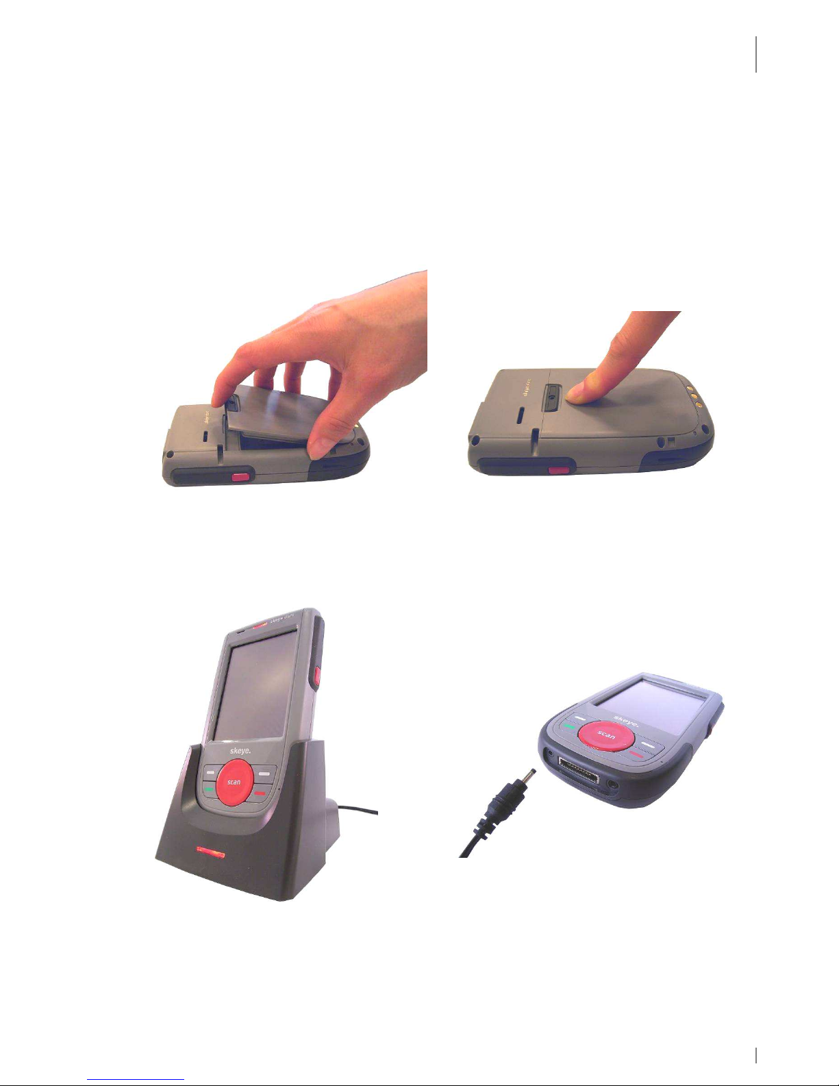
3.4.1 Inserting the Battery
There is only one way to insert the battery.
Insert the battery with its noses at the rounded part into the relevant recesses
inside the battery compartment. Press the battery until it audibly engages. See also
chapter 3.4.2.
Fig. 12: inserting the battery
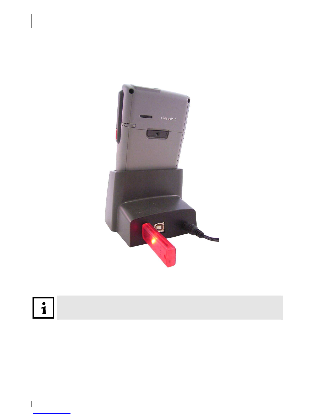
Prior to initial operation the battery should be charged completely. To do so, insert
the mobile terminal including battery into the communication cradle (connected to
power) or connect the power supply unit to the device.
Fig. 13: mobile terminal in communication cradle / mobile terminal connect to power supply unit
To remove the battery press the battery lock down and remove (see chapter 3.4.2).
Page 24

TAKING INTO OPERATION
Battery
24 1.04 • 19.05.2010
3.4.2 Replacing the Battery
1. Back up your data before changing the battery.
2. Switch off the device before changing the battery.
Push the battery locking down, keep it pressed and
remove the battery.
To re-insert the battery, insert it with its noses at the
rounded part into the relevant recesses inside the
battery compartment. Press the battery until it audibly
engages. See also chapter 3.3.
Fig. 14: Changing the battery
3.4.3 Charging the Battery
The battery in the skeye.dart is automatically recharged if the skeye.dart is
• connected to the power supply unit
• placed in the communication cradle (with connected power supply unit)
The Systray displays one of the following symbols:
Battery is charging
The battery is below the first voltage level.
The battery is below the second voltage level.
There is an external power supply but the battery is not charged (full
battery)
Always recharge the battery in time. If the battery is discharged data loss may
occur.
Battery locking
Page 25

TAKING INTO OPERATION
Switching On/Switching Off the skeye.dart
19.05.2010 • 1.04 25
3.5 Switching On/Switching Off the skeye.dart
3.5.1 Switching On
The mobile terminal is switched-on by pressing the round button in the middle.
Fig. 15: switch-on the device
3.5.2 Switching Off the skeye.dart
There are three ways to switch off your skeye.dart:
♦ Suspend mode
♦ Automatic Standby
♦ Complete Power Off by Removing the Battery
3.5.2.1 Suspend Mode
Suspending a device means that it is inactive and thus consumes less power. A
suspended skeye.dart can be activated any time.
While suspending information in the RAM of the skeye.dart is maintained. If the
power supply is interrupted e.g. due to a discharged battery, information in the
RAM gets lost.
It is thus recommended that you store all current data in the flash or on SD card
prior to suspending the skeye.dart
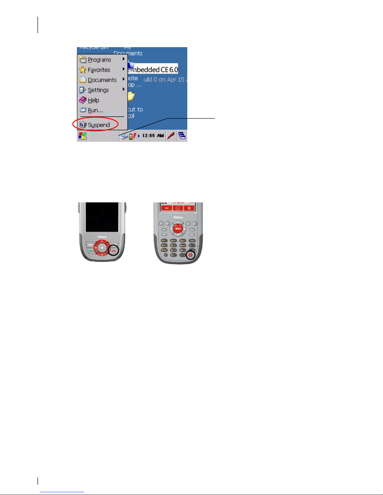
Suspending the skeye.dart:
1. Tap [Start] in the task bar.
The Start menu opens up.
Power-on
button
Power-on
button
Page 26
TAKING INTO OPERATION
Switching On/Switching Off the skeye.dart
26 1.04 • 19.05.2010
Fig. 16: Start menu
2. Tap Suspend.
or
3. Press the red key (bottom right) for about 5 sec or the On/Off key (bottom
right) at the skeye.dart XKE for about 2 sec.
about 5 sec about 2 sec
The skeye.dart will be suspended in its current state. All open windows, documents,
workbooks etc. are not closed but maintained in the working memory.
The skeye.dart is suspended.
If the power supply was not interrupted e.g. due to a discharged battery the data
will be available again when you switch on/start the device.
Task bar
Page 27
TAKING INTO OPERATION
Switching On/Switching Off the skeye.dart
19.05.2010 • 1.04 27
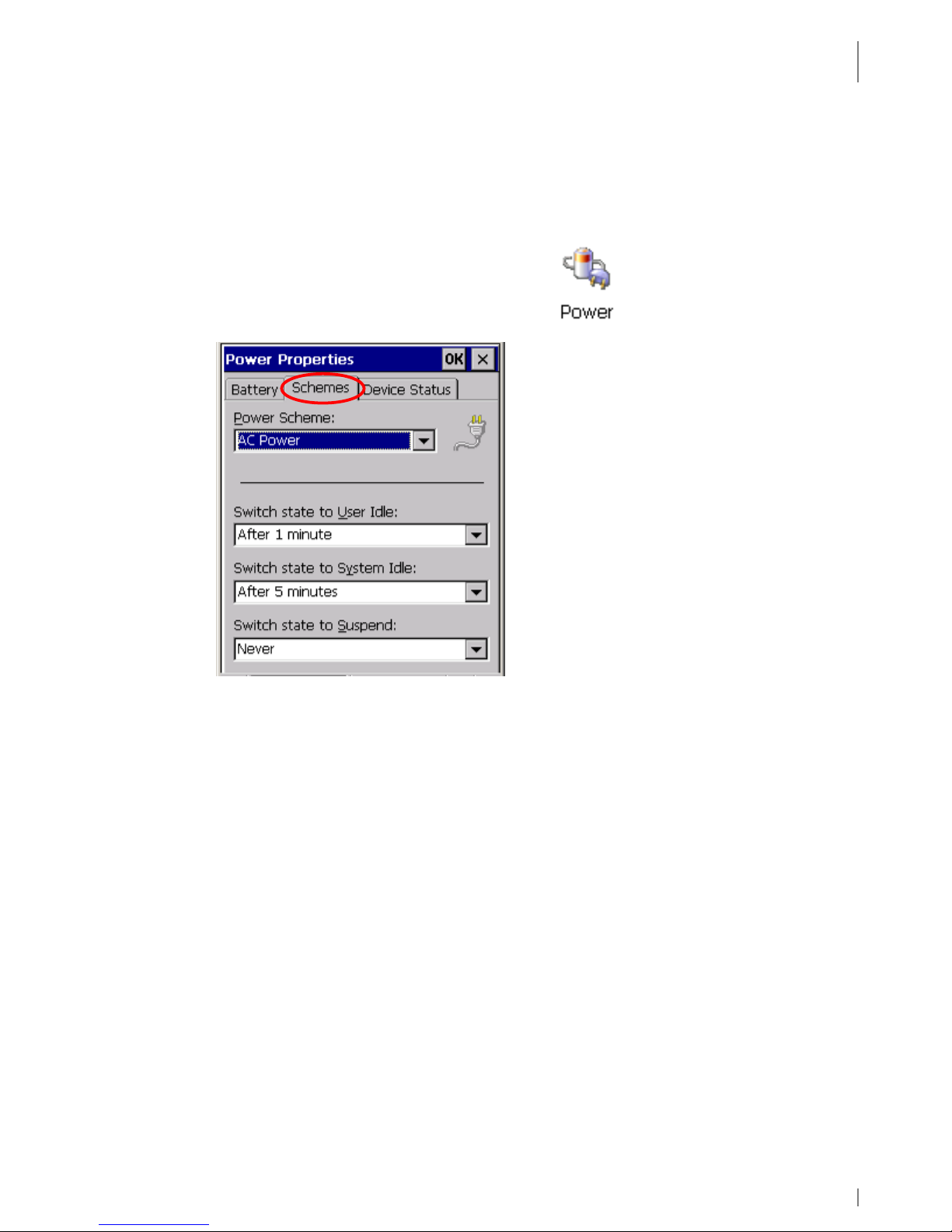
3.5.2.2 Automatic Standby – Power Supply
Use the Power Supply function to save battery life. If you do not operate the unit
for a certain time e.g. the display will be dimmed or the unit is set to suspend
mode.
1. Launch: Start ⇒ Settings ⇒ Control Panel.
The Control Panel menu appears.
2. In the Control Panel menu double tap Power.
The Power Properties window appears.
3. Select the Schemes tab.
Fig. 17: Automatic power off
4. Perform the desired settings.
The entered times are added up.
(Example: after 1 min user idle, after 5 min system idle)
5. Click [OK] to confirm the changes.
6. Close the Control Panel menu.
See also chapter 4.2.7.2.
Page 28

TAKING INTO OPERATION
Switching On/Switching Off the skeye.dart
28 1.04 • 19.05.2010
3.5.2.3 Complete Power Off by Removing the Battery
Completely power off your skeye.dart in the following situations:
♦ if you do not operate your skeye.dart for a longer period of time (battery
saving)
♦ when entering an aircraft.
♦ in explosive areas
♦ for shipping the skeye.dart
Removing the battery will delete the RAM after a while. In this case, all data in the
RAM e.g. installed programs, settings or stored files are lost!
A mobile terminal with 128 MB SDRAM can keep the RAM files about 10 minutes
(if the buffer is completely charged which takes about 20 minutes).
If the buffer is not completely charged, the time decreases correspondingly.
We recommend before removing the battery:
1. Save data first.
2. Suspend the skeye.dart. Then, wait for about 10 sec. Only then the RAM is
sustained.
3. At last, remove the battery.
Page 29

INITIAL STEPS
Operating the skeye.dart with the Stylus
19.05.2010 • 1.04 29
4. Initial Steps
1. Insert the battery (see chapter 3.4.2).
2. Switch on the skeye.dart by pressing the middle scan key.
3. Take out the stylus (Fig. 8: Rear view).
4.1 Operating the skeye.dart with the Stylus
The stylus functions as a computer mouse. It is used to navigate on the screen and
to select elements.
Remove the stylus from its clamp and put it back when you do not need it.
Operate the touch screen only with the stylus supplied or your finger.
Tapping
Tap the screen with the stylus once to open elements and to select
options.
Dragging
On screen, keep the stylus pressed and drag it over the screen to
select text and pictures. Move the stylus to a list to select several
elements.
Double-tap
A double-tap is the same as double-clicking the mouse.
Tap and hold
Tap on an element and keep the stylus pressed onto the screen to
display a list of actions for the element.
In a context menu, select the
action to be performed.
Tapping (close menu)
To close a menu (e.g. the start menu) tap a free space on the
desktop.
Page 30
INITIAL STEPS
Microsoft Windows CE – Basics
30 1.04 • 19.05.2010
4.2 Microsoft Windows CE – Basics
This mobile terminal supports the following Windows CE version: 6.0 (copy
deadline, subject to changes).
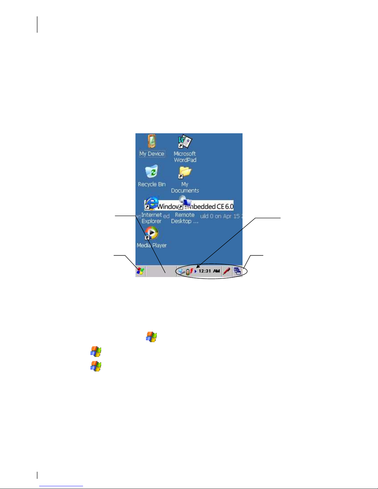
4.2.1 Start Screen
Apart from the application program the Mobile Terminal features the Windows CE
surface. The following figure shows the standard Windows CE workspace which may
vary.
Fig. 18: Start Screen
4.2.2 Start Menu
Use the Start menu to call programs, change settings, manage favourites etc.
• In the task bar tap the symbol to open the Start menu.
• Tap and then select Programs to call further programs.
• Tap and then select Settings to perform further settings.
Desktop
Start
menu
Task bar
Systray
Further
program
symbols
Page 31

INITIAL STEPS
Microsoft Windows CE – Basics
19.05.2010 • 1.04 31
4.2.3 Desktop Symbols
The following list contains an explanation of the symbols which can usually be found
on a Windows CE surface:
Symbol Program Description
My Device
Displays the storage locations available on the mobile terminal
e.g. Flash Storage as well as the network. Due to its link to the
system control the My Device also provides for a direct access
to the system management tools.
My
documents
This is your personal folder.
Windows creates personal folders for
each mobile terminal user.
Recycle bin
Here, Windows stores deleted files. Files deleted by mistake may
be restored.
Internet
Explorer
Searches web and WAP sites and downloads new programs and
files from the internet.
Word Pad
Creates new documents and displays Word documents created
on the desktop PC for further editing.
Remote
Desktop
TerminalClient to establish a terminal server connection
4.2.4 Taskbar
The taskbar is a special workspace component which can be used to switch between
open windows and to access global commands and frequently used objects.
Symbols of the taskbar (examples):
Tap one of these symbols in the taskbar (depending on the activated
keypad) and select the keypad type or “Hide input panel”.
To display all activated programs tap this symbol which can be found in the
bottom right area of the taskbar.
To minimise all open windows tap in the bottom right area of the taskbar
and then select "Desktop"
.
Page 32
INITIAL STEPS
Microsoft Windows CE – Basics
32 1.04 • 19.05.2010
4.2.5 Right Mouse Button Function
The right mouse button is used to open popup menus that support functions like
Copying, Deleting, and Sending.
To call the functions of the right mouse button tap the element for which you want
to perform the action and keep the stylus pressed.
The popup window of the right mouse button displays. Here, you can select the
desired function.
If you do not wish to perform an action, tap any position outside the menu.
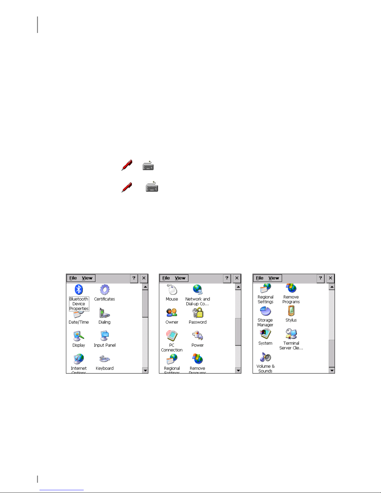
4.2.6 Showing/Hiding the Keyboard
Showing: Tap or
in the taskbar and select the desired keyboard.
Hiding: Tap or in the taskbar (depending on the activated keypad)
and select "Hide input panel".
4.2.7 Basic Settings
The basic settings are mainly performed on the control panel.
Launch: Start ⇒ Settings ⇒ Control Panel
The Control Panel window appears.
Fig. 19: Control Panel
Page 33

INITIAL STEPS
Microsoft Windows CE – Basics
19.05.2010 • 1.04 33
4.2.7.1 Calibrating the Touch Screen
This function is required to fine-tune the touch screen; the better the touch screen
is calibrated the more precisely it will react.
When calibrating the touch screen note the following:
• Touch the cross and keep the stylus pressed at the middle of the cross until the
cross moves to the next marking.
• Do not drag the stylus over the touch screen.
• Do not rest your hand on the touch screen!
1. Launch: Start ⇒ Settings ⇒ Control Panel
2. Double-tap the Stylus symbol.
The Stylus "Properties window" appears.
Fig. 20: Stylus Properties
Page 34

INITIAL STEPS
Microsoft Windows CE – Basics
34 1.04 • 19.05.2010
3. In the Stylus Properties window tap the Calibration tab.
Fig. 21: Stylus Properties | Calibration
4. On the Calibraton tab select Recalibrate.
The window for calibrating the touch appears.
5. Position the stylus in the centre of the cross displayed (the more precise, the
better the touch screen will respond later) and hold the position until the cross
changes its position.
6. Click [ENTER] to confirm.
7. Close the Stylus Properties menu.
8. Please answer the question with [Yes] if the settings should be stored
persistently.
Over time, the touch screen, and thus its calibration, may reset somewhat. Should
you notice that the touch screen does not respond as precisely as before, repeat
the calibration procedure.
Page 35

INITIAL STEPS
Microsoft Windows CE – Basics
19.05.2010 • 1.04 35
4.2.7.2 Setting the Brightness
1. Launch: Start ⇒ Settings ⇒ Control Panel
The "Control Panel" menu appears.
2. In the Control Panel window double tap the following symbol:
The “Display Properties” window appears.
3. In the Display Properties window tap the Backlight tab.
4. Set the interval and situation during which the backlight should be switched off.
Fig. 22: Backlight
5. Then, click [Advanced].
6. In this window, adjust the brightness of the backlight with the slider.
To conserve battery power, keep the brightness setting as low as possible.
7. Click [OK] to confirm the setting.
Page 36

FURTHER FUNCTIONS AND SETTINGS
Setting of Display Orientation and -Dissolution
36 1.04 • 19.05.2010
5. Further Functions and Settings
Start ⇒ Programs ⇒ Utilities …
5.1 Setting of Display Orientation and -Dissolution
Select: Start ⇒ Programs ⇒ Utilities ⇒ DisplaySet
Select the appropriate depiction/dissolution and confirm
with [OK]:
Fig. 23: Display settings
5.2 Scan of Barcodes
Call HWImagerTool to test the scanner function:
Start ⇒ Programs ⇒ Utilities ⇒ HWImagerTool
HWImagerTool executes in the background and can be identified by the SystTray
symbol.
HWImagerTool can be used to scan into any text field (e.g. WordPad).
Calmly and angularly hold the skeye.dart in the direction of the barcode to be
scanned. A peep indicates that the entry of the barcode has been successful. The
gap should amount to about 5-10 cm. An aid to orientation could be the skeye.dart
lettering: aim with the red dot.
For more information please enquire for a separate HWImagerTool user guide.
Programming interfaces for Imager/Camera are available.
Page 37

FURTHER FUNCTIONS AND SETTINGS
Scan Keys
19.05.2010 • 1.04 37
5.3 Scan Keys
For scanning or camera operation you can use the middle round key or the keys at
the sides.
= Scanner keys
Fig. 24: Scanner keys
5.4 SysAP
Launch: Start ⇒ Programs ⇒ Utilities ⇒ SysAP
The following settings are supported:
• WIFI Power: on or off
• Bluetooth Power: on or off
• Vibrator Power: test
• Setting of loudspeaker and microphone
Fig. 25: SysAP
Page 38

FURTHER FUNCTIONS AND SETTINGS
Soundset
38 1.04 • 19.05.2010
5.5 Soundset
Launch: Start ⇒ Programs ⇒ Utilities ⇒ Soundset
The following settings can be performed:
• Speaker: Loudspeaker volume for internal
and/or loudspeaker of headsets
Scroll the controller and tap [sample] to
check the adjusted volume.
You can increase the volume with "Boost".
• Microphone: Microphone volume for the
internal or microphone of the headset
Scroll the slider to increase the recording
volume of the microphone.
• The program Wavetest (Start ⇒ Programs ⇒
Utilities ⇒ wavetest) allows you to take
recordings with the microphone and to replay
them.
Fig. 26: Soundset
Fig. 27: Wav Test
"SysAP" also absorbs the changes made here for the loudspeakers (and vice
versa). Please see previous chapter.
Start ⇒⇒⇒⇒ Programs ⇒⇒⇒⇒ Utilities ⇒⇒⇒⇒ SysAP ⇒⇒⇒⇒ tab "Voice Control"
Page 39
FURTHER FUNCTIONS AND SETTINGS
System Info
19.05.2010 • 1.04 39
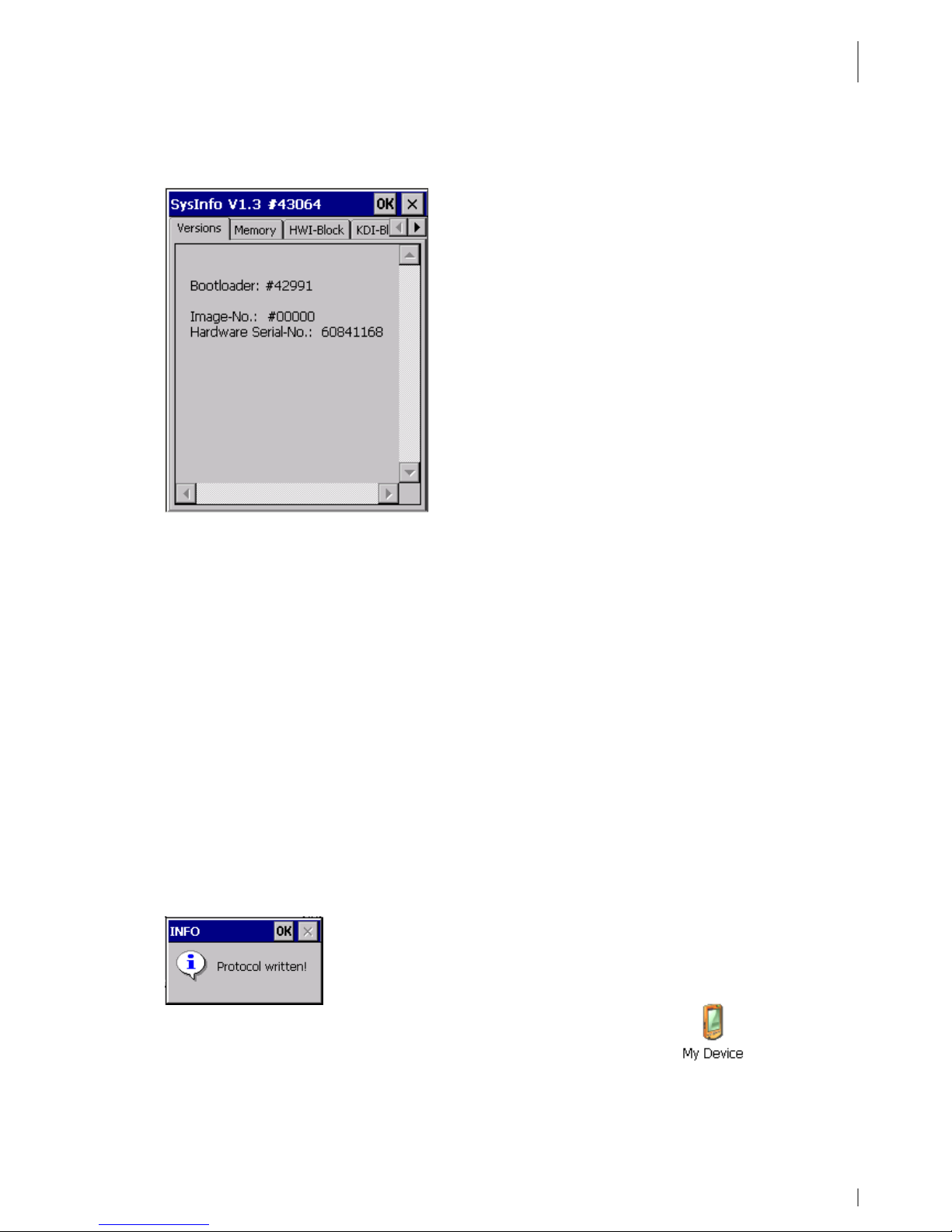
5.6 System Info
Launch: Start ⇒ Programs ⇒ Utilities ⇒ System Info
Fig. 28: SysInfo
♦ The Versions tab displays information on operating system, serial number, and
battery parameters.
♦ The Memory tab displays information on physical memories, drives and data
memories.
♦ Operating system and system programs (e.g. an update tool) can read the
hardware configuration of the devices from the HWI-Block (Hardware
Information Block).
♦ The KDI-Block (Customer information block) stores customer specific settings.
♦ The GSI-Block tab (device specific information block) contains device specific
information.
Tap [x] to close the window.
SysInfo Report File
When closing the SysInfo window with [OK] a report file (SysinfoReport.txt) is
created containing the same information as SysInfo
With a double tap on the symbol My Device you can view the file.
Page 40

FURTHER FUNCTIONS AND SETTINGS
SysBackup
40 1.04 • 19.05.2010
Fig. 29: Report File
Please include the report file in case of a support request.
5.7 SysBackup
Using SysBackup you can
• create
• restore and
• delete a backup.
NOTES:
⇒ Backup data saved with SysBackup should only be restored in one image and on
the same hardware under which they were created, as otherwise problems may
occur.
⇒ If the option for asking the user is deactivated before the backup is created your
are not prompted for confirmation after the booting process.
⇒ SysBackup only stores and restores data but does not delete them. This might be
important in the following szenario:
When you need a cleaned up desktop you can delete the "My Computer" and
"Recycle Bin" symbols using a setting in "ExplorerConfig" as the symbols are
created on the desktop via RegistryKey. However, all other symbols on the desktop
are created in the \windows\desktop directory using *.Ink-files. From there, they
have to be deleted in the autostart directory using a corresponding batch file as
after a cold start of the device these files are automatically stored at this location
while booting and are not deleted when you restore a backup.
Open "SysInfoReport.txt".
Page 41

FURTHER FUNCTIONS AND SETTINGS
SysBackup
19.05.2010 • 1.04 41
5.7.1 Calling SysBackup
Start SysBackup via
• Start ⇒
⇒⇒
⇒ Run ⇒⇒⇒⇒ SysBackup (enter SysBackup) or
• Start ⇒
⇒⇒
⇒ Programs ⇒⇒⇒⇒ System ⇒⇒⇒⇒ SysBackup
The "SysBackup" window appears.
Fig. 30: SysBackup
Select [autobackup settings] to perform further settings.
An automatic backup interval that is too short will have a negative effect on
the performance.
Backup controlled by battery status
Backup is time
-
controlled (every 15 min.)
Page 42
FURTHER FUNCTIONS AND SETTINGS
SysBackup
42 1.04 • 19.05.2010
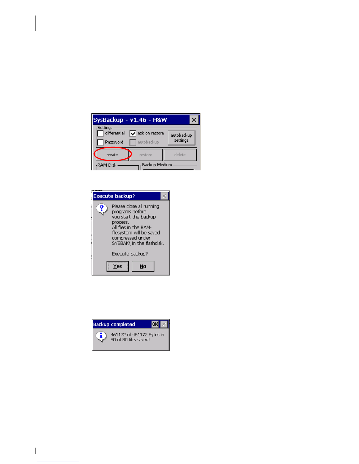
5.7.2 Creating a Backup
Copy all important data to the "\FlashStorage" folder or its subfolders.
Everything must be backed up to ensure system settings are not lost after a battery
has fully discharged or there has been a total shutdown.
1. Open the SysBackup program (see chapter 5.7.1).
2. In the SysBackup window tap [create].
The message "Execute backup?" appears.
Fig. 31: Execute backup?
3. Click [Yes] to confirm.
The SysBackup is performed. After completion the following message
displays:
Fig. 32: Backup completed
4. Click [OK] to close the message.
5. Click [Exit] to close the window.
Page 43

FURTHER FUNCTIONS AND SETTINGS
SysBackup
19.05.2010 • 1.04 43
5.7.3 Restoring the Backup
Backup data saved with SysBackup should only be restored in one image and on
the same hardware under which they were created, as otherwise problems may
occur.
1. Open the SysBackup program (see chapter 5.7.1).
2. Select [restore].
The message "Execute restore?" appears.
Fig. 33: Execute restore?
3. Click [Yes] to confirm the message.
The backup will be imported.
If there is no backup after a restart or if a backup is not required (e.g. after a
warm start) the Sysbackup program searches all flash media (including the
FlashStorage memory card) for the autostat.exe application. If such
application is found it will be executed. There is an autostart mechanism
independent from the registry as Sysbackup will always be automatically
performed after the system start.
Please note:
All RAM data will be overwritten. All data will be updated to the state prevailing at
the time of backup creation.
Page 44
FURTHER FUNCTIONS AND SETTINGS
SysBackup
44 1.04 • 19.05.2010
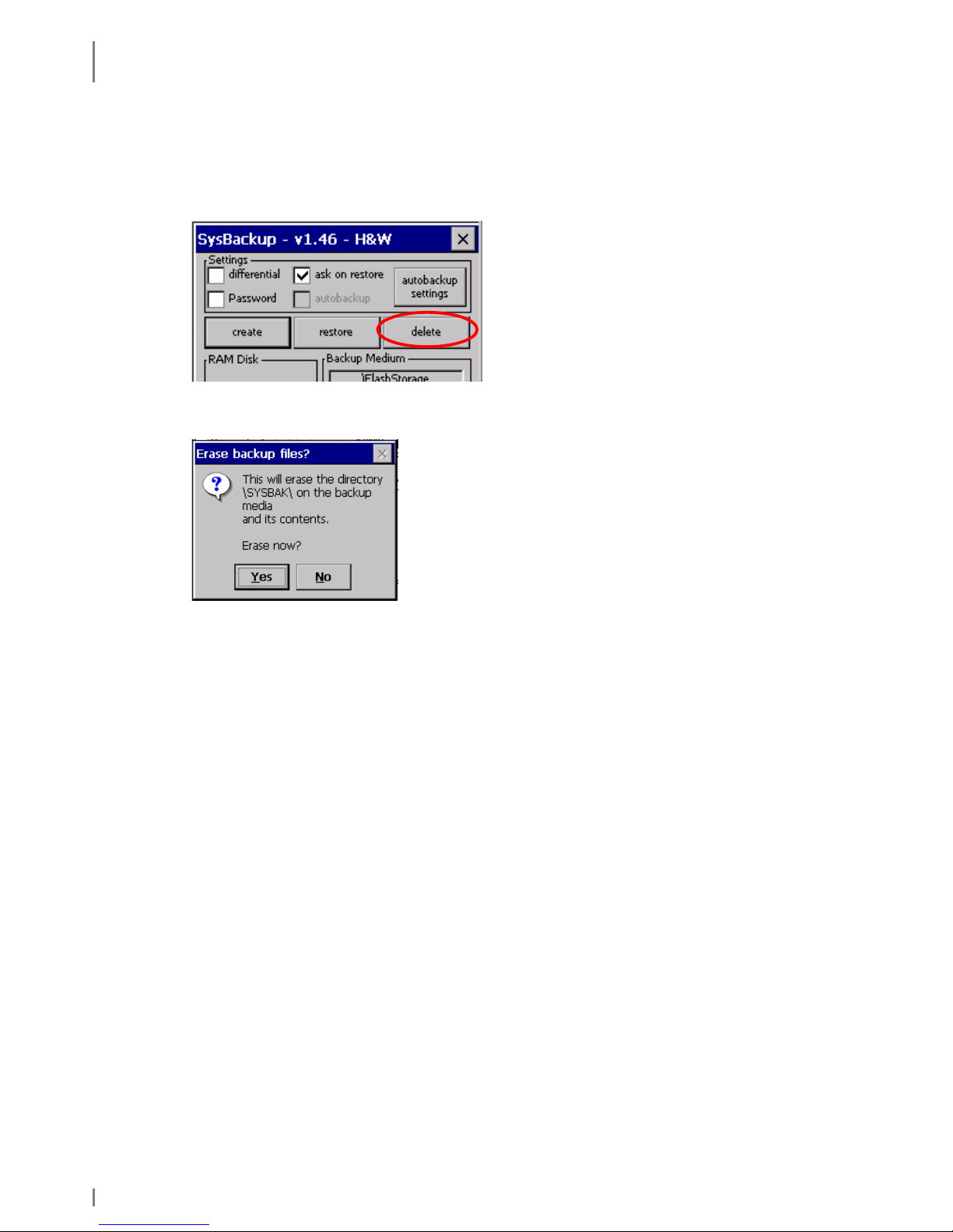
5.7.4 Deleting a Backup
1. Open the SysBackup program (see chapter 5.7.1).
2. Tap [delete].
The message "Erase backup files?" appears.
Fig. 34: Erase backup files
3. Click [Yes] to confirm the message.
The content of the \FlashStorage\SYSBAK directory will be deleted.
Page 45
RADIO
Wireless LAN
19.05.2010 • 1.04 45
6. Radio
6.1 Wireless LAN
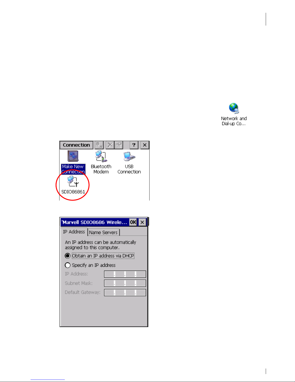
6.1.1 Wireless LAN Network Settings
1. Set up a Wireless LAN access point that provides access to a LAN or the
Internet. Follow the instructions of your Wireless LAN access point
documentation.
2. Launch on the skeye.allegro: Start ⇒ Settings ⇒ Control Panel ⇒
Network and Dial-up Connections
or
Start ⇒ Settings ⇒ Network and Dial-up Connections
3. Double-tap the WiFi module.
4. Activate Obtain an IP address via DHCP. DHCP is activated by default.
Fig. 35: Wireless LAN | IP address
5. To manually set the IP addresses enter the addresses under IP address,
Subnet mask, Gateway and tab Nameservers.
Page 46
RADIO
Wireless LAN
46 1.04 • 19.05.2010
6. Tap [OK] for all queries to exit the dialog.
6.1.2 Wireless LAN Configuration
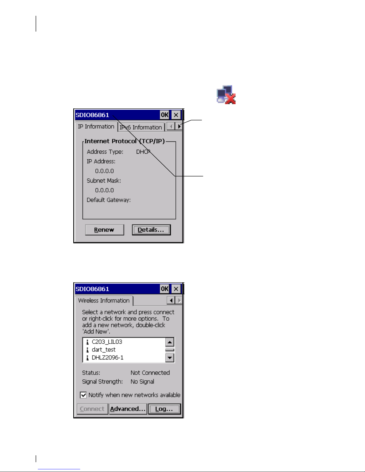
1. Double-tap the network symbol in the Systray.
The following window appears.
Fig. 36: Wireless LAN
2. Below the Wireless Information tab you can select the required network from
the list.
Fig. 37: Wireless LAN | Wireless Information
Further tabs
Here, the name of the module
used displays
Page 47
RADIO
Wireless LAN
19.05.2010 • 1.04 47
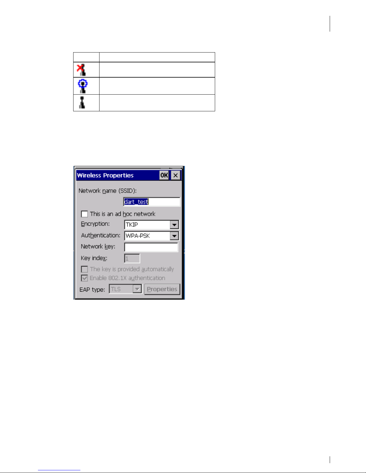
Symbol Meaning
Network not available
Available network connected
Network available
Fig. 38: Network symbols
3. On the Wireless Information tab select a network and double-tap the
corresponding selection for further options.
The following window appears:
Fig. 39: Wireless – Properties
4. If you selected Add new... as the network on the Wireless Information tab
fill in the fields.
• SSID is the name of the network used to determine your Wireless LAN
network. To ensure a communication between all network computers be
sure to use the same SSID for all. SSID is the address set in the access
point.
• When accessing via an access point, option This is a computer-to-
computer (ad hoc) network is not activated.
• Encryption is used to prevent unauthorised access to the network. Enter
the common network key (password). This ensures that data is
encrypted when being transferred over the network.
• The encryption type is set under Encryption. Under Authentication,
set the method used by a Wireless LAN client to logon to an access point
(e.g. WPA).
Page 48

RADIO
Wireless LAN
48 1.04 • 19.05.2010
• The network key and the network name (SSID) must be the same as
used for the configuration of the access point.
5. Tap [OK] to close the window.
The network symbol displays in the taskbar.
Be sure to protect your Wireless LAN network. We recommend that you consult a
specialist (such as a System house).
6.1.3 Entering the Network ID
To get access to network resources enter information on the network identification.
1. Launch: Start ⇒ Settings ⇒ Control Panel ⇒ Owner
The Owner Properties window appears.
2. Select the Network ID tab.
Fig. 40: Owner Properties | Network ID
3. On the Network ID tab fill in the fields and click [OK] to confirm.
Page 49

RADIO
GSM Control
19.05.2010 • 1.04 49
6.2 GSM Control
*only available in the skeye.dart FFE version
If you wish to dial into the internet, for example via GSM/GPRS/EDGE, further
settings are necessary.
First, please check if the GSM module is switched on.
1. Select: Start ⇒ Settings ⇒ Control Panel
2. Double tap the symbol "GsmControl".
3. Tap [OK]. If not already so, the GSM module is now switched on and activated.
6.2.1 Establishing a Connection
Before establishing a connection, please ask your provider for the connection
settings and the APN (Access Point Name).
1. Insert the SIM card given by your provider into the SIM card slot of the mobile
terminal (see also chapter 3.3).
2. Switch on the mobile terminal.
3. After start of the operating system the PIN of the SIM card is asked.
4. Enter the PIN given by your provider into the displayed keyboard.
With every new registration and after a suspend mode the PIN number is asked
again. In case you wish to set the PIN number persistently, please follow the
instructions in chapter 6.2.2.1.
The check mark at "Enable GSM module"
has to be set.
Page 50

RADIO
GSM Control
50 1.04 • 19.05.2010
5. If neither in the module nor in the registry an APN (Access Point Name) is
entered, you will be asked to give the APN of the provider:
6. Double tap the active GSM symbol at the bottom of the Systray.
The following menu is displayed:
7. Select "Connect" to establish a connection via GPRS.
The GPRS connection is established.
Further comment:
With "Connect" or "Disconnect" an Internet connection is activated or deactivated.
The following symbols in the Systray explain the status:
= not connected
= connected
Page 51

RADIO
GSM Control
19.05.2010 • 1.04 51
6.2.2 Further Settings
6.2.2.1 Persistent Setting of the PIN Number
With every new registration and after a suspend mode the PIN number is asked. In
order to avoid its entry each time, please proceed as follows:
1. Call: Start ⇒ Settings ⇒ Control Panel ⇒ GsmControl
2. Select index card SIM.
3. Enter the PIN and activate Persistent; thus, even after a reset the PIN is
sustained and has not to be entered again.
4. Afterwards please tap [Set Pin] and then [OK].
Page 52
RADIO
GSM Control
52 1.04 • 19.05.2010
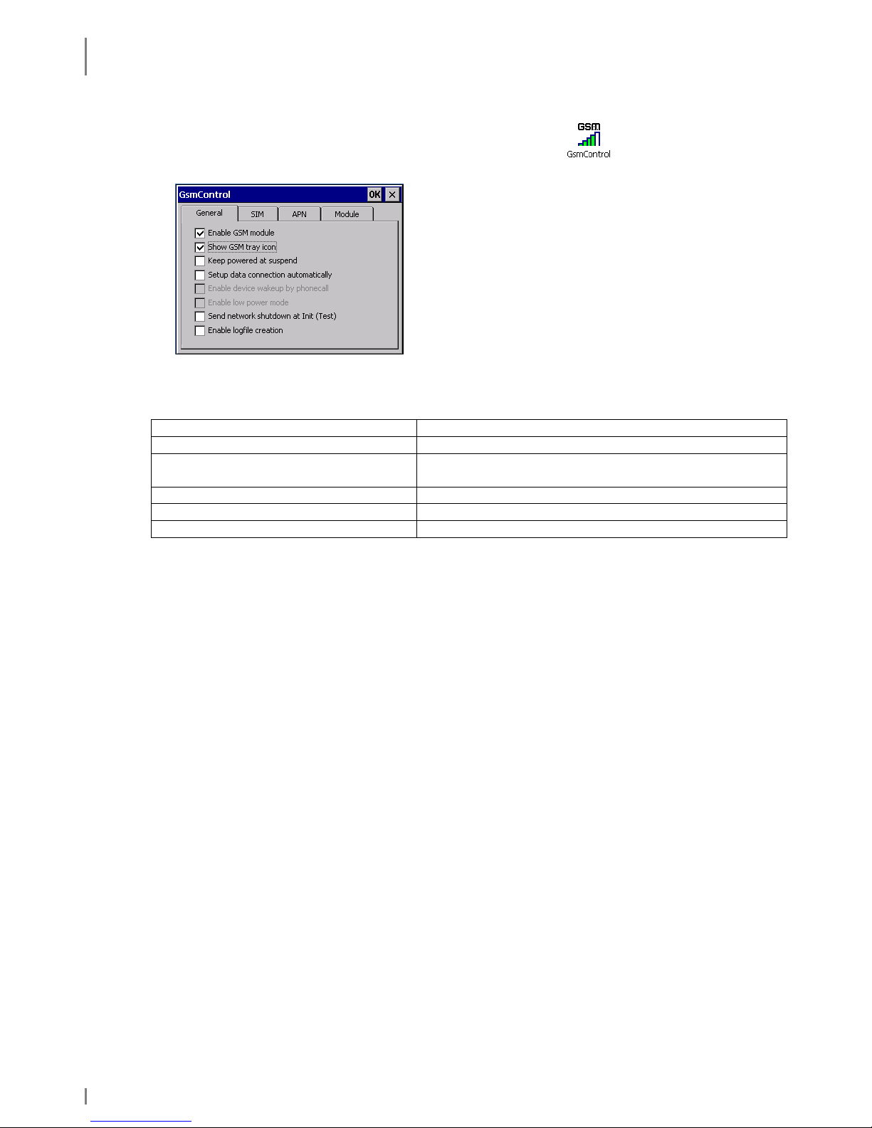
6.2.2.2 General Settings
1. Call: Start ⇒ Settings ⇒ Control Panel ⇒ GsmControl
2. Select index card General.
The following settings are available:
Enable GSM module Enable the GSM module
Show GSM tray icon Show the GSM symbol in the systray
Keep powered at suspend* Power supply of the GSM module also during
suspend mode (battery life time). See below.
Setup data connection automatically GSM connection is always started automatically
Send network shutdown at Init Logout from provider network
Enable logfile creation Generating a log file (under flash storage)
*Keep powered at suspend
Complete GSM switch-off at suspend
Advantage: Low power consumption at suspend
Disadvantage: When switching off the device a new login is necessary (waiting
time). The PIN has to be entered repeatedly (exception: it is set
persistently in the device, see chapter 6.2.2.1)
GSM module is kept powered at suspend
Advantage: Short waiting time after switching-on. The device remains locked in
(allows functions as tracking or Wakeup via call).
Disadvantage: Increased power consumption
Page 53

RADIO
GSM Control
19.05.2010 • 1.04 53
6.2.2.3 APN
1. Call: Start ⇒ Settings ⇒ Control Panel ⇒ GsmControl
2. Select index card APN.
Here you can change the APN afterwards, e.g. in
case of wrong entries or a new provider
6.2.2.4 GSM Info
1. Call: Start ⇒ Programs ⇒ Communication ⇒ GsmInfo
Some important information is displayed in this window.
Here, signal volume and –quality of the GSM
connection as well as further connection information
are displayed.
If you set a checkmark at T, this information is
always in the foreground.
Please set a checkmark in the box below right to
select further items.
Please set a checkmark in the box below right to
select further items
Page 54

RADIO
GPS Module
54 1.04 • 19.05.2010
Data rates:
GSM = 2G
GPRS = 2,5G
EDGE = 2,75G
Depend on provider and net capacity.
6.3 GPS Module
*only available in the skeye.dart FFE version
You can start GPS with a terminal program of your own choice by activating the
GPS module via COM6 with 9600 Baud.
Page 55
COMMUNICATION CRADLES
Communucation Cradle (USB Standard)
19.05.2010 • 1.04 55
7. Communication Cradles
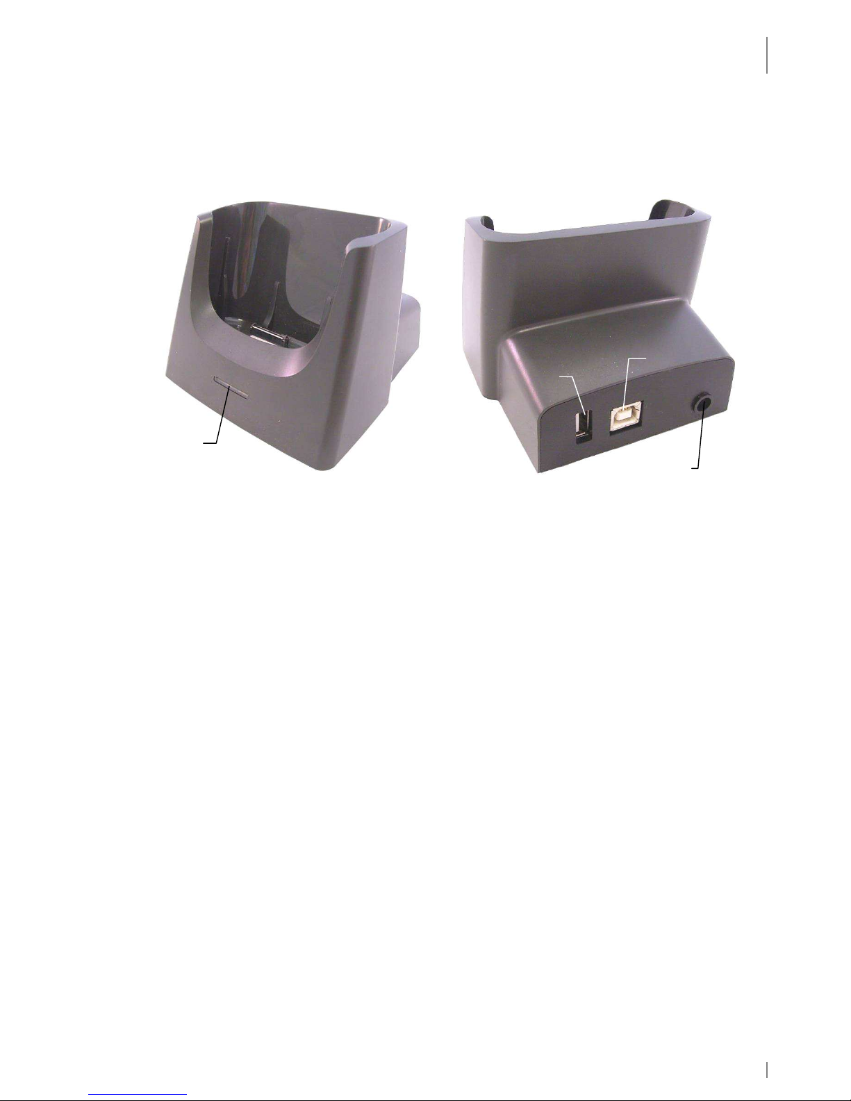
7.1 Communucation Cradle (USB Standard)
Fig. 41: Communication cradle | front and rear view
• LED: The red LED at the communication cradle indicates a
connection to power.
• Connections: USB host, USB device, DC-in, system interface to the mobile
terminal
7.2 Technical Data
Casing: Shock resistant plastic, self-extinguishing according to UL94V-0
Slots: One slot for the mobile terminal including battery.
Ports &
Connectors
• Connection for HW 14240 power supply, DC voltage input
Mini DC Power Jack ∅ 1,3 mm, 5 V / 2.8 A
• System interface to the mobile terminal
• USB device
USB 1.1
Connection to a PC to communicate via
ActiveSync possible
• USB host USB 1.1
Connection to USB devices 500 mA, 5 V
LED: 1 red LED on the front panel signals communication cradle operating
status
Battery
charging:
• Charging in mobile terminal: controlled by the mobile terminal
charging electronics
• Charging duration: approx. 2.5 h (HW 19240)
Ambient
conditions:
• Operate only indoors
• Ensure good ventilation is available
LED
USB host
USB device
power supply
Page 56

COMMUNICATION CRADLES
Charging the Battery in the Communication Cradle
56 1.04 • 19.05.2010
• Operating temperature:
-
limit values: 0 °C to +40 °C,
-
recommended range: 10 °C to +30 °C,
• Storage temperature: -20 °C to +60 °C
• Humidity: up to 85 % (non-condensing)
Rules and
Standards:
• CE conformity
• ElektroG and RoHs conformity
Dimensions: • about 95 mm x 95 mm x 75 mm (L x W x H)
Weight: • about 140 g
7.3 Charging the Battery in the Communication Cradle
• Connect the communication cradle to power. The red LED of the communication
cradle glows.
• Insert the mobile terminal (incl. battery) in the communication cradle. The LED
of the mobile terminal glows red.
• When the LED of the mobile terminal glows green the battery is fully charged.
• Charging time: about 2.5 h
7.4 Connecting the Communication Cradle to the Desktop PC
Fig. 42: Connecting the communication cradle to the desktop PC
Communication cradle: USB device ⇔ PC: USB host
USB host
Page 57

COMMUNICATION CRADLES
Desktop Cradle (USB with Battery Charger)
19.05.2010 • 1.04 57
7.5 Desktop Cradle (USB with Battery Charger)
Fig. 43: Desktop cradle | front and rear view
• LED: • Glows red: spare battery is charging.
• Glows green: spare battery is fully charged.
• Glows blue: cradle is operational, no spare battery in slot.
• Connections: USB host, USB device, DC-in, system interface to the mobile
terminal
7.6 Technical Data
Casing: Shock resistant plastic, self-extinguishing according to UL94V-0
Slots: • One slot for the mobile terminal including battery.
• One additional slot for battery charging.
Ports &
Connectors
• Connection for HW 14240 power supply, DC voltage input
Mini DC Power Jack ∅ 1,3 mm, 5 V / 2.8 A
• System interface to the mobile terminal
• USB device
USB 1.1
Connection to a PC to communicate via
ActiveSync possible
• USB host USB 1.1
Connection to USB devices 500 mA, 5 V
LED: 1 LED on the front panel signals desktop cradle and spare battery (see
above) operating status
Battery
charging:
• Charging in mobile terminal: controlled by the mobile terminal
charging electronics
• Charging in battery charger: controlled by charging electronics in
the desktop cradle
• Charging duration: approx. 2.5 h (HW 19240) or
approx. 5 h (HW 19241)
LED
USB host
USB d
evice
Power supply
Spare battery
Battery charger
Page 58

COMMUNICATION CRADLES
Charging the Battery in the battery charger slot
58 1.04 • 19.05.2010
Ambient
conditions:
• Operate only indoors
• Ensure good ventilation is available
• Operating temperature:
-
limit values: 0 °C to +40 °C,
-
recommended range: 10 °C to +30 °C,
• Storage temperature: -20 °C to +60 °C
• Humidity: up to 85 % (non-condensing)
Rules and
Standards:
• CE conformity
• ElektroG and RoHs conformity
Dimensions: • about 114 mm x 100 mm x 75 mm (L x W x H)
Weight: • about 215 g
7.7 Charging the Battery in the battery charger slot
• Connect the desktop cradle to power. The LED of the desktop cradle glows blue.
• Insert the battery into the battery charger slot of the desktop cradle. The LED
glows red.
• When the LED glows green the battery is fully charged.
• Charging time: about 2.5 h (HW 19240) or about 5 h (HW 19241).
Page 59

COMMUNICATION CRADLES
Communication skeye.dart ( PC
19.05.2010 • 1.04 59
7.8 Communication skeye.dart ⇔⇔⇔⇔ PC
• Install on your PC the program for data synchronisation of a PC with a mobile
device. This program should be appropriate to your operational system:
Microsoft ActiveSync ⇒ for Windows XP
Windows Mobile Device Center (WMDC) ⇒ for Windows Vista
Device Stage ⇒ for Windows 7
These programs are available for free via www.Microsoft.com/getstarted. With
these programs you can handle the following tasks:
• Add and remove programs on your skeye.dart
• Synchronise files
• Transfer and copy files
Page 60
COMMUNICATION CRADLES
Application of USB Host
60 1.04 • 19.05.2010
7.9 Application of USB Host
Example:
Put an USB stick into the connector of the USB Host of the communication cradle.
The skeye.dart has now access to the data of the USB stick.
Fig. 44: Communication cradle | USB stick
NOTE!
Please do connect only USB devices to the USB host of the communication
cradle that consume not more than max. 500 mA to 5 V.
Page 61

TECHNICAL DATA
Application of USB Host
19.05.2010 • 1.04 61
8. Technical Data
Casing: Rugged case, protection level IP54, drop spec 1,2 m
Processor: CPU Marvell PXA 320, 624 MHz
Memory: 128 MB DDRAM, 256 MB Flash
Display: 3,5 " VGA colour TFT with touchscreen
Keyboard: • Two keyboard versionen available (5 keys/9 keys)
• 2-side scan buttons
• Individually backlit keys for intuitive operation
LED: 2-colour LED indication:
• red: battery is charging
• green: battery is fully charged
Further
equipment:
• Camera 2 MP, autofokus, with barcode decodierung function,
camera flash light and aimer or 2D-Imager
• Microphone, Receiver, Speaker
Communication: • Wireless LAN IEEE 802.11 b/g
• Bluetooth 2.0
• GSM/GPRS/EDGE (only FFE)
• GPS (only FFE)
Battery: Rechargeable battery pack 2100 mAh (lockable)
Interfaces: • USB 1.1 host port (Full Speed)
• USB 1.1 device port (Full Speed)
• RS232 port (TxD, RxD, RTS, CTS)
• Micro-SD card slot (lockable)
• DC-in connector
• Headset connector
Temperature
Range:
Operating temperature: –10 °C bis + 50 °C
Size: 145 mm x 79 mm x 25 mm
Weight: 270 g (including battery)
Rules and
Standards:
• CE Marking
• German ElektroG and RoHS conformity
Page 62
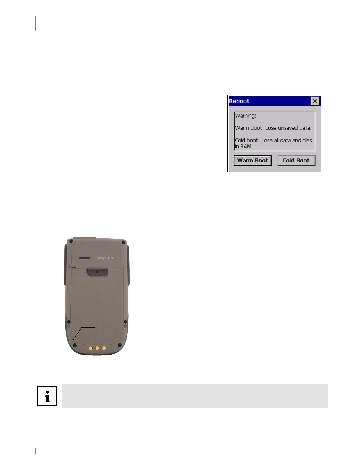
TROUBLESHOOTING
Reset via Software
62 1.04 • 19.05.2010
9. Troubleshooting
9.1 Reset via Software
If an application does not react use the software to perform a restart.
Via function
Start ⇒⇒⇒⇒ Programs ⇒⇒⇒⇒ Utilities ⇒⇒⇒⇒ Reboot
A warm or a cold start of the device can be activated.
The system restarts. Unsaved data will be lost.
Fig. 45: Reboot
9.2 Reset via Hardware
If the touch screen does not react or if you cannot switch on the device, press the
reset button.
Use the stylus to initiate the reset.
Fig. 46: skeye.dart, Reset
First press (according to keyboard version) the middle
key in the navigation field (or the scan key), keep it
pressed and then press additionally the reset key.
Press the reset key carefully with low expenditure
of force.
After a hardware reset, all data and settings in RAM are deleted from your mobile
terminal. Data in FLASH are not deleted.
Reset
key
Page 63

TROUBLESHOOTING
Reset via Hardware
19.05.2010 • 1.04 63
Manufacturer's Address
Höft & Wessel AG
Skeye
Rotenburger Str. 20
30659 Hannover, Germany
Tel. +49 511 6102-0
Fax. +49 511 6102-411
Mail. info@skeye.com
Web. www.skeye.de
Service line.
within Germany: +49 1803 232829
( 0.09 € per min)
from abroad: +49/511/6102-600
 Loading...