

Skee Ball Hot Shot Installation And Operation Manual
Hot Shot Basketball
Installation and Operation
Manual 990445
02 Oct 15; rev 23+
Skee Ball, Inc., 121 Liberty Lane, Chalfont, PA 18914
Voice: (215) 997-8900
Fax: (215) 997-8982

Table of Contents
WARNINGS....................................................................................................................... 4
SPECIFICATIONS ........................................................................................................... 5
ASSEMBLY SEQUENCE ................................................................................................ 6
Power–Up Sequence........................................................................................................ 24
Game Overview ............................................................................................................... 24
Idle Display (Attract Mode) ........................................................................................... 24
Coins ................................................................................................................................. 24
Game Play ........................................................................................................................ 24
Scoring ............................................................................................................................. 24
End Of Game ................................................................................................................... 24
Credits .............................................................................................................................. 24
Tickets .............................................................................................................................. 24
MAJOR COMPONENTS .............................................................................................. 26
Controller Assembly ................................................................................................... 26
Program / Counter PCB (Printed Circuit Board) ................................................... 26
Programming Display ................................................................................................. 26
Power Supply ............................................................................................................... 26
Ball Release Actuator ................................................................................................. 27
Speakers ....................................................................................................................... 27
Ticket Dispenser .......................................................................................................... 28
Coin Mechanisms (Coin Mechs) / Cash Box............................................................. 28
2

Game Time and Score Displays ................................................................................. 29
Opto-Sensors ............................................................................................................... 29
SD Card (contains certain sound data) ..................................................................... 30
Game Options / How to program .................................................................................. 31
“Discount Games” Programming Examples: ............................................................... 33
FOR YOUR RECORDS… ............................................................................................. 34
TICKET DISPENSER .................................................................................................... 35
Basic operation of ticket dispenser model DL1275H ........................................... 35
Ticket Dispenser Components ............................................................................... 35
Conditions That Could Cause the Ticket Error To Be Announced. .................. 36
Loading of Tickets................................................................................................... 36
Ticket Dispenser Replacement ............................................................................... 36
Parts Reference ............................................................................................................... 37
GENERAL TROUBLESHOOTING ............................................................................. 38
Returned Components .................................................................................................... 39
WARRANTY................................................................................................................... 40
Wire Schematic ............................................................................................................... 41
3

WARNINGS
Read this manual thoroughly before assembling your game. Failure to follow the
instructions could cause damage to your game and void your warranty. In addition,
the manual explains the game in detail and the options you have so that you and
your players can enjoy the game to its fullest.
A. The power cord must be plugged into a grounded, three-prong outlet.
Failure to do so could cause permanent injury or game damage.
B. This game is suitable for indoor use only. The game should not be installed
outdoors or in areas directly exposed to sunlight, high humidity, direct water
contact, dust, high heat or extreme cold. Installation in any such environment shall
void the warranty.
C. Only trained personnel should conduct replacement of fuses, lamps and any
other servicing on the product.
4

SPECIFICATIONS
HOT SHOT BASKETBALL GAME
all TBD
Height xx in
Width xx in
Length xx in
Weight xxx lbs. Uncrated
xxx lbs. Crated
Power Maximums:
115 VAC, x.0 AMPS
xxx WATTS
Power Averages:
115 VAC, x.0 AMPS
xxx WATTS
5
ASSEMBLY SEQUENCE
Assembly of Hot Shot will require 2 or 3 strong people, tools, and about 4 hours
of time.
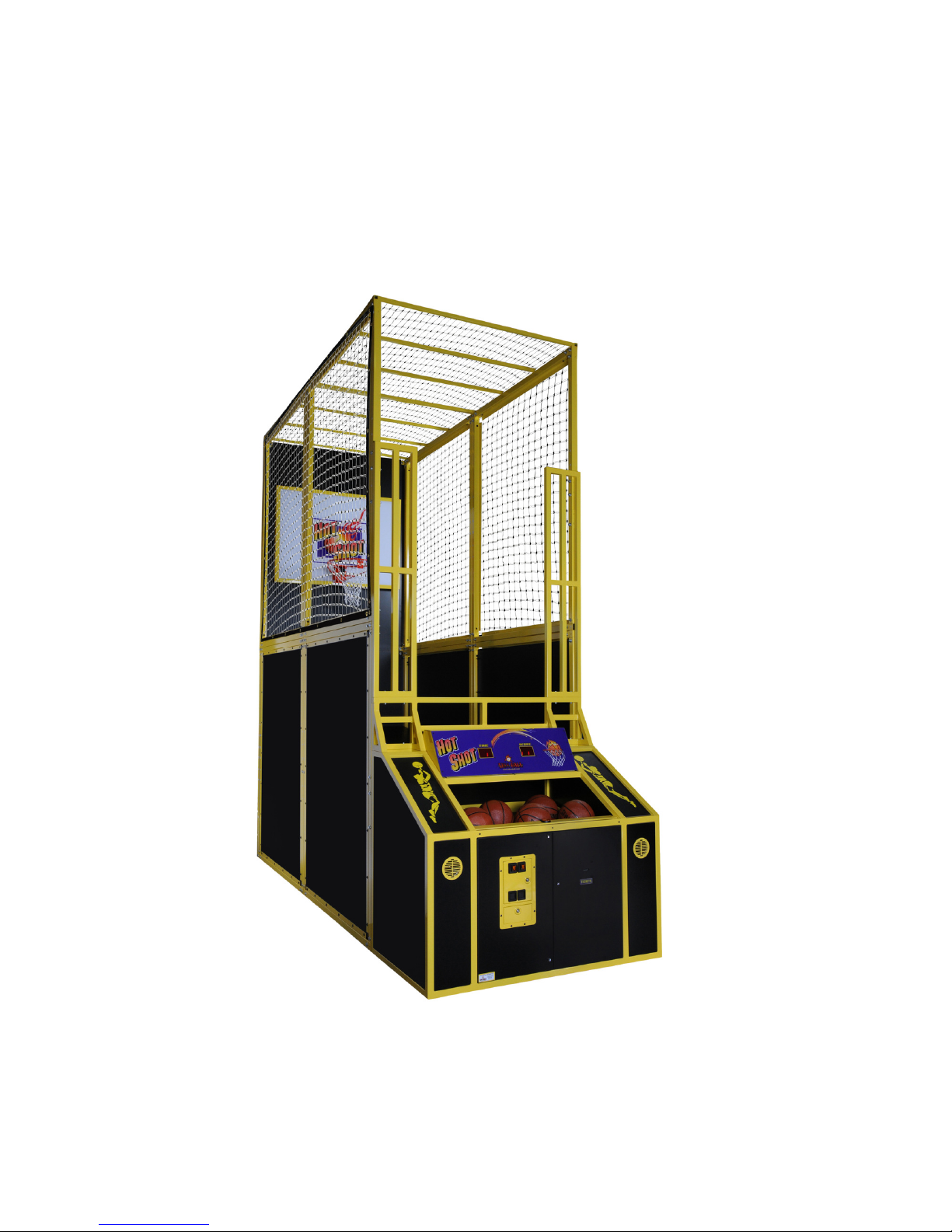
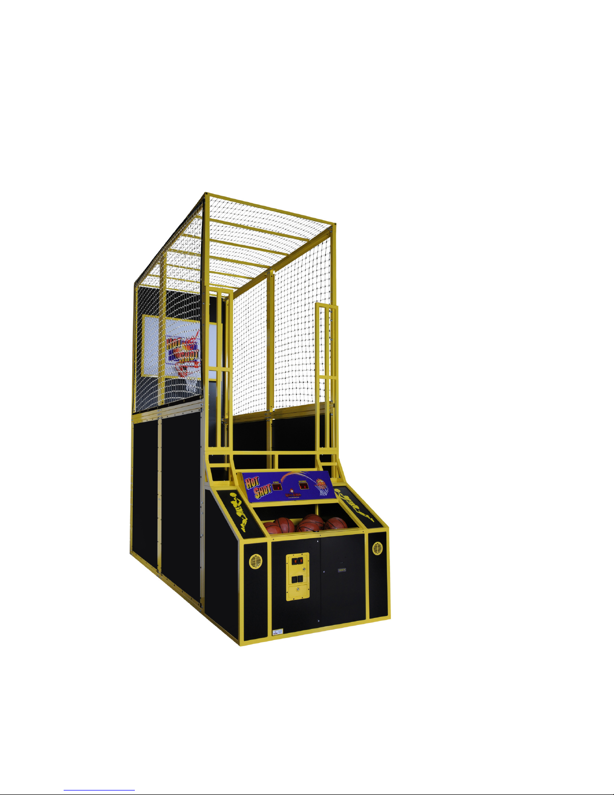
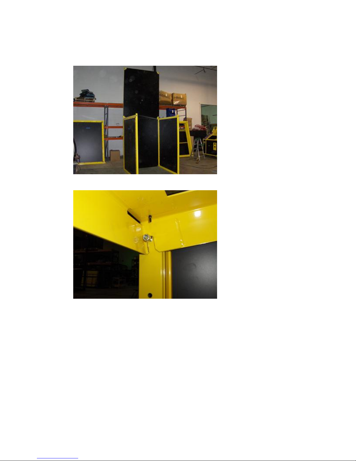
Here is a photo of the finished assembly of the game:
6

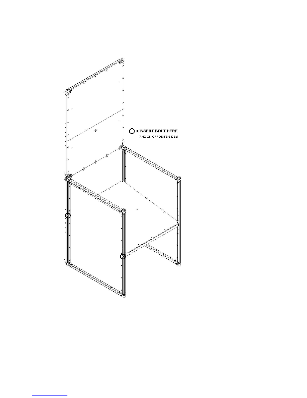
Here is an isometric drawing of the finished assembly of the game:
7

Step 1:
Assemble the lower back panel with both the lower right and left rear panels:
Qty 4) 3/8 16 x 1” bolt
Qty 8) 3/8 washer
Qty 4) 3/8 16 nylock nut
8
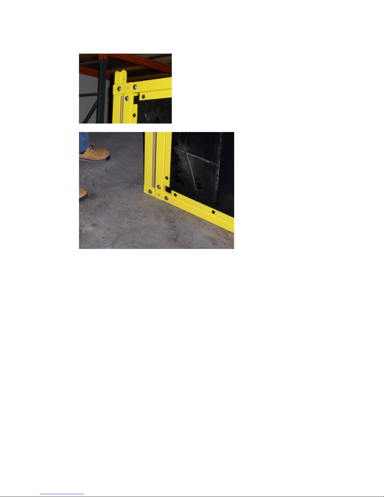
NOTE: Tighten the 1” bolts via the hole in the back of the game.
9
10
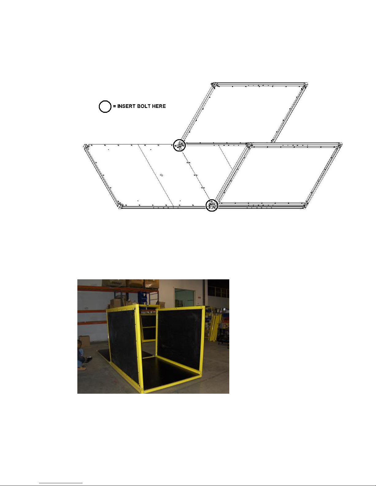
Step 2:
Tip the assembly on its back, and attach the upper back panel to the lower back panel:
Qty 2) 3/8 16 x 2 3/4” bolt
Qty 4) 3/8 washer
Qty 2) 3/8 16 nylock nut
11
12
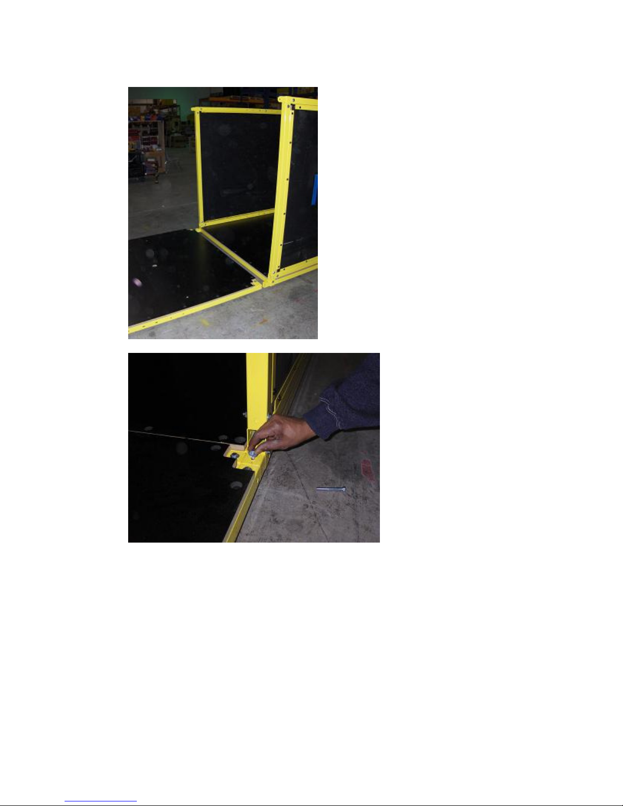
Step 3:
Stand this assembly upright and attach the rear playfield floor:
Qty 4) 3/8 16 x 3” bolt
Qty 4) specially modified 3/8 washer
Qty 4) 3/8 washer
Qty 4) 3/8 16 nylock nut
NOTES: Insert the 3” bolts through the side holes, but do not tighten.
Hang the rear floor onto bolts (underneath.)
13
Use the specially modified washers on the inside of the bolt.
The flat of the specially modified washer avoids a clearance problem.
 Loading...