

Page 1

USER MANUAL
PL20 Series Hybrid Inverter
Page 2

CONTENTS
ABOUT THIS MANUAL
................................................................................................................................................
1
Purpose
............................................................................................................................................................................
1
Scope
................................................................................................................................................................................
1
IMPORTANT SAFETY INSTRUCTIONS
....................................................................................................................
1
General Precautions
.......................................................................................................................................................
1
Personal Precautions
.....................................................................................................................................................
2
INSTALLATION
...............................................................................................................................................................
3
Unpacking and Inspection
.............................................................................................................................................
3
Basic Configuration
.........................................................................................................................................................
3
Batteries
............................................................................................................................................................................
4
Battery Cable Size
..........................................................................................................................................................
6
DC Disconnect and Over-Current Protection
.............................................................................................................
6
Battery Cable Connection
..............................................................................................................................................
6
AC Cable Size
.................................................................................................................................................................
7
AC Connections
..............................................................................................................................................................
7
Machine panel introduction
............................................................................................................................................
9
OPERATION
..................................................................................................................................................................
11
Front Panel and Configuration Switch
.......................................................................................................................
11
Setting Indicators
..........................................................................................................................................................
12
LCD display meaning
...................................................................................................................................................
17
Table 5. display meaning
.............................................................................................................................................
17
Operating Indicators
.....................................................................................................................................................
18
Table 6 Fault code meaning
........................................................................................................................................
19
SPECIFICATIONS
........................................................................................................................................................
20
Table 7. Line Mode Specifications
..............................................................................................................................
20
Table 8. Invert Mode Specifications
...........................................................................................................................
21
Table 9. AC Charger Mode Specifications
................................................................................................................
22
Table 10. Solar Charger Mode Specifications
..........................................................................................................
22
Table 11. General Specifications
................................................................................................................................
23
APPENDIX A
.................................................................................................................................................................
24
How to Select and Configure PV Panels
..................................................................................................................
24
DISPOSAL
.....................................................................................................................................................................
26
Page 3

1
ABOUT THIS MANUAL
Purpose
The purpose of this manual is to provide explanations and procedures for installing, operating and
troubleshooting for the unit. This manual should be read carefully before installations and operations.
Please retain this manual for future reference.
Scope
This document defines the functional requirements of the unit, intended for worldwide use in electronic
processing equipment. All manuals are applicable under all operating conditions when installed in the End
Use system, unless otherwise stated.
IMPORTANT SAFETY INSTRUCTIONS
WARNING: This chapter contains important safety and operating instructions. Read and keep
this User Guide for future reference.
General Precautions
1. Before using the unit, read all instructions and cautionary markings on:
(1) The unit (2) the batteries (3) all appropriate sections of this manual.
2. CAUTION --To reduce risk of injury, charge only deep-cycle lead acid type rechargeable batteries. Other
types of batteries may burst, causing personal injury and damage.
3. Do not expose the unit to rain, snow or liquids of any type. The unit is designed for indoor use only.
Protect the unit from splashing if used in vehicle applications.
4. Do not disassemble the unit. Take it to a qualified service center when service or repair is required.
Incorrect re-assembly may result in a risk of electric shock or fire.
5. To reduce risk of electric shock, disconnect all wiring before attempting any maintenance or cleaning.
Turning off the unit will not reduce this risk.
6. CAUTION --Battery are not already installed by the supplier only a qualified professional (e.g. service
person) may install the Inverter.
7. WARNING: WORKING IN VICINITY OF A LEAD ACID BATTERY IS DANGEROUS.
BATTERIES GENERATE EXPLOSIVE GASES DURING NORMAL OPERATION. Provide ventilation to
outdoors from the battery compartment. The battery enclosure should be designed to prevent
accumulation and concentration of hydrogen gas in “pockets” at the top of the compartment. Vent the
battery compartment from the highest point. A sloped lid can also be used to direct the flow to the vent
opening location.
8. NEVER charge a frozen battery.
9. No terminals or lugs are required for hook-up of the AC wiring. AC wiring must be no less than 10 AWG
gauge copper wire details refer to table 2. Battery cables must be rated for 35mm or higher and should be
no less than table 1. Crimped and sealed copper ring terminal lugs with a HRNB38-8 hole should be used
to connect the battery cables to the DC terminals of the unit. Soldered cable lugs are also acceptable.
10. Be extra cautious when working with metal tools on, or around batteries. The potential exists to drop a
tool and short-circuit the batteries or other electrical parts resulting in sparks that could cause an
explosion.
Page 4

2
11. No AC or DC disconnects are provided as an integral part of this unit. Both AC and DC disconnects
must be provided as part of the system installation. See INSTALLATION section of this manual.
12. Fuses are provided as the over current protection of the battery supply.
13. When PV module or panel is exposed to light, it starts to supply high DC voltage, be sure to turn off DC
switch before commencing the maintenance, and make sure the cables from PV panel are properly
sealed after disconnection.
14. GROUNDING INSTRUCTIONS -This battery charger should be connected to a grounded permanent
wiring system. For most installations, the Ground Lug should be bonded to the grounding system at one
(and only one point) in the system. All installations should comply with all national and local codes and
ordinances.
15. AVOID AC output short-circuit; avoid DC input short-circuit and do not connect the mains while DC input
short-circuit
16. Warning: The maintenance information is only to service persons, If the product is used in a manner
which is not covered by the scope of warranty, the protection provided by the product may be impaired.
Personal Precautions
1. Someone should be within range of your voice to come to your aid when you work near batteries.
2. Have plenty of fresh water and soap nearby in case battery acid contacts skin, clothing, or eyes.
3. Wear complete eye protection and clothing protection. Avoid touching eyes while working near batteries.
Wash your hands when done.
4. If battery acid contacts skin or clothing, wash immediately with soap and water. If acid enters eyes,
immediately flood eyes with running cool water for at least 15 minutes and get medical attention
immediately.
5. Baking soda neutralizes lead acid battery electrolyte. Keep a supply on hand in the area of the batteries.
6. NEVER smoke or allow a spark or flame in vicinity of a battery or generator.
7. Be extra cautious when working with metal tools on, and around batteries. Potential exists to short-circuit
the batteries or other electrical parts which may result in a spark which could cause an explosion.
8. Remove personal metal items such as rings, bracelets, necklaces, and watches when working with
battery. Battery can produce short-circuit current high enough to weld a ring, or the like, to metal causing
severe burns.
9. If a remote or automatic generator start system is used, disable the automatic starting circuit and/or
disconnect the generator from its starting battery while servicing to prevent accidental starting during
servicing.
Page 5

3
INSTALLATION
Unpacking and Inspection
Carefully unpack the inverter/charger from its shipping carton.
Verify all of items list below are present. Please call customer service if any items are missing.
The unit
1 user’s manual
Basic Configuration
PL20 Series hybrid Inverter is designed to serve as a backup power supply for AC loads. The input power of
PL20 Series hybrid Inverter comes from PV system and AC grid which not only supply power to AC loads but
also charge the battery bank when the power from AC grid or AC generator is present (also known as Line
Mode).
In the event of AC grid (or AC generator) outage, the AC loads can be alternatively powered by PV system (if
the illumination is sufficient) and battery bank.
The following illustrations show basic applications for PL20 Series hybrid Inverter.
Figure 1. Typical Application of PL20 series hybrid Inverter
Page 6

4
Note: Appliances like Air conditioner needs at least 3 minutes to restart in case of a power shortage occurs
in a way that the power turns off then back on again rapidly (time is required to balance the refrigerant
gas in inside circuit); so in order to protect your Air conditioner, please consult the Air conditioner
manufacturer whether they have already provided time delay function before installing. Otherwise,
Inverter will trig overload fault and shut off its output to protect your appliance but sometimes it is not
enough and your Air conditioner can be damaged internally beyond repair.
Batteries
The unit support 12volt,24volt or 48vlot battery bank. Please wiring battery correctly. Before proceeding,
ensure you have appropriate size batteries for this inverter. The unit can use flooded lead-acid, or sealed
GEL/AGM lead-acid batteries so ensure that your batteries are in one of these categories. PL20 inverter
with built-in MPPT solar controller, for the battery and solar panel connection please refer to figure 2,figure3
and figure4. If with the built-in 48 MPPT 40A solar charge controller, then please configure solar panels
more than 2350W, otherwise it can not reach the maximum charge current, if with the built-in 48 MPPT 60A
solar charge controller, then please configure solar panels more than 3500W, otherwise it can not reach
the maximum charge current.
Note: if you are using a gel battery or a deep cycle battery, please do not use ordinary lead-acid batteries for
use in solar energy systems. This is likely to damage the lead acid battery or to reach the desired
effect.
The battery must be wired to match with the DC input voltage. Recommend to use battery capacity more
than 200AH .
Figure 2. PL20 12V solar inverter system- the connection diagram of solar panel and battery
Page 7

5
Figure 3. PL20 24V solar inverter system- the connection diagram of solar panel and battery
Figure 4. PL20 48V solar inverter system- the connection diagram of solar panel and battery
Page 8

6
Battery Cable Size
Below table 1 you can find information for recommended battery cable and terminal.
Table 1. Recommended battery cable and terminal size
Model
Number
DC
Voltage
Typical
Amperage
Battery
Capacity
1~3 m
one-way
0.5 m
one-way
Cable Terminal
PL20 1KW
PL20 2KW
PL20 4KW
12V
24V
48V
120A
200AH
25mm
2
25mm
2
RNBS38-8
PL20 5KW
48V
150A
200AH
35
mm
2
25
mm
2
RNBS38-8
PL20 1.5KW
PL20 3KW
PL20 6KW
12V
24V
48V
175A
200AH
50
mm
2
35
mm
2
RNB60-8/RNBS38-8
PL20 2KW
PL20 4KW
PL20 8KW
12V
24V
48V
225A
200AH
50
mm
2
35
mm
2
RNB60-8/RNBS38-8
PL20 5KW
PL20 10KW
24V
48V
275A
200AH
75mm
2
50mm
2
RNB80-8/RNB60-8
PL20 3KW
PL20 6KW
PL20 12KW
12V
24V
48V
315A
200AH
75mm
2
50mm
2
RNB80-8/RNB60-8
DC Disconnect and Over-Current Protection
For safety and to comply with regulations, battery over-current protection and disconnect devices are
required. Fuses and disconnects must be sized to protect the DC cable size used, and must be rated for DC
operation. Do not use devices rated only for AC service – they will not function properly.
Note that some installation requirements may not require a disconnect device, although over-current
protection is still required.
Battery Cable Connection
Observe Battery Polarity! Place the ring terminal of DC cable over the bolt and directly against the unit’s
battery terminal. Tighten the M8 screw with 6-10 Nm. Do not place anything between the flat part of the
Backup System terminal and the battery cable ring terminal or overheating may occur.
DO NOT APPLY ANY TYPE OF ANTI-OXIDANT PASTE TO TERMINALS UNTIL AFTER THE BATTERY
CABLE WIRING IS TORQUED!!
WARNING: Shock Hazard
Installation must be performed with care for the high battery voltage in series.
Caution!! Do NOT place anything between battery cable ring terminals and terminals on the
inverter. The terminal screw is not designed to carry current.
Apply Anti-oxidant paste to terminals AFTER terminals have been screwed.
Verify that cable lugs are flush with the battery terminals. Tighten battery cables to terminals (6-10 Nm).
Page 9
7
AC Cable Size
Before wiring the input and output of inverter, refer to table 2 for minimum recommended cable size and
torque value
Table 2. Recommended cable size and torque value for AC wire
Model Number
Typical
Amperage
AC Input
AC Output
Torque value
PL20 1KW 230Vac
10A
12AWG
14AWG
1.5~2.0 Nm
PL20 1.5KW 230Vac
12A
12AWG
14AWG
1.5~2.0 Nm
PL20 2KW 230Vac
PL20 1KW 110Vac
15A
12AWG
12AWG
1.5~2.0 Nm
PL20 3KW 230Vac
PL20 1.5KW 110Vac
20A
12AWG
12AWG
1.5~2.0 Nm
PL20 4KW 230Vac
PL20 2KW 110Vac
32A
12AWG
12AWG
1.5~2.0 Nm
PL20 5KW 230Vac
40A
12AWG
12AWG
1.5~2.0 Nm
PL20 6KW 230Vac
PL20 3KW 110Vac
50A
10AWG
12AWG
1.5~2.0 Nm
PL20 8KW 230Vac
PL20 4KW 110Vac
60A
10AWG
10 AWG
2.0~2.5 Nm
PL20 10KW 230Vac
PL20 5KW 110Vac
70A
8AWG
10 AWG
2.0~2.5 Nm
PL20 12KW 230Vac
PL20 6KW 110Vac
80A
6AWG
8AWG
2.0~2.5 Nm
AC Connections
Installation should be done by a qualified electrician. Consult local code for the proper wire sizes,
connectors and conduit requirements.
On the left of rear chassis is the AC hardwire cover. Two three-station terminal block is provided to make the
AC connections. The terminal block is used to hardwire the AC input, AC output, and ground. The National
Electrical Code requires that an external disconnect switch be used in the AC input wiring circuit. The AC
breakers in a sub panel will meet this requirement.
Page 10

8
Figure 5. AC Cable Connect to unit
Step 1: Disconnect the unit from the battery by removing the battery cables. Turning off the unit before
disconnect from the battery.
Step 2: Following the wiring guide located in the AC input wiring compartment as figure 5, connect the GND
(green/yellow), Line (brown), and neutral (blue) wires from the AC input (utility, generator, etc) to
the terminal block.
Caution!! Be sure that AC source is disconnected before attempting to hardwire it to the unit.
Step 3: Connect the AC Line output wiring to the terminal marked AC Line (output), following the wiring
guide inside the compartment. Torque the wires into the terminal block.
Step 4: Lock the AC covers.
Page 11

9
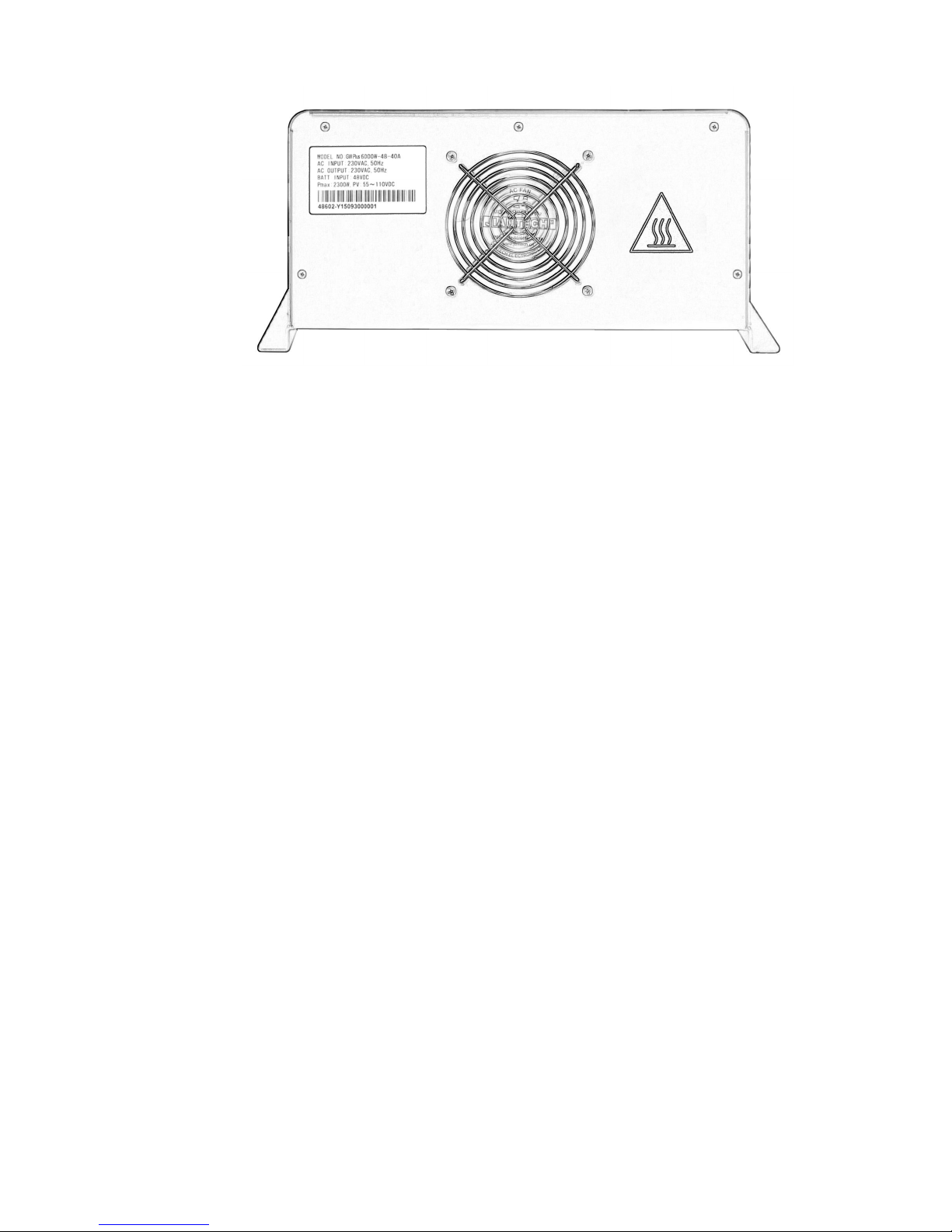
Machine panel introduction
Figure 6. PL201-3KW
Front
panel
Figure 7. PL201-3KW Back panel
Figure 8. PL204-6KW
Front
panel
Page 12
10
Figure 9. PL204-6KW Back panel
Figure 10. PL208-12KW Front panel
Figure 11. PL208-12KW Back panel
Page 13
11
OPERATION
Front Panel and Configuration Switch
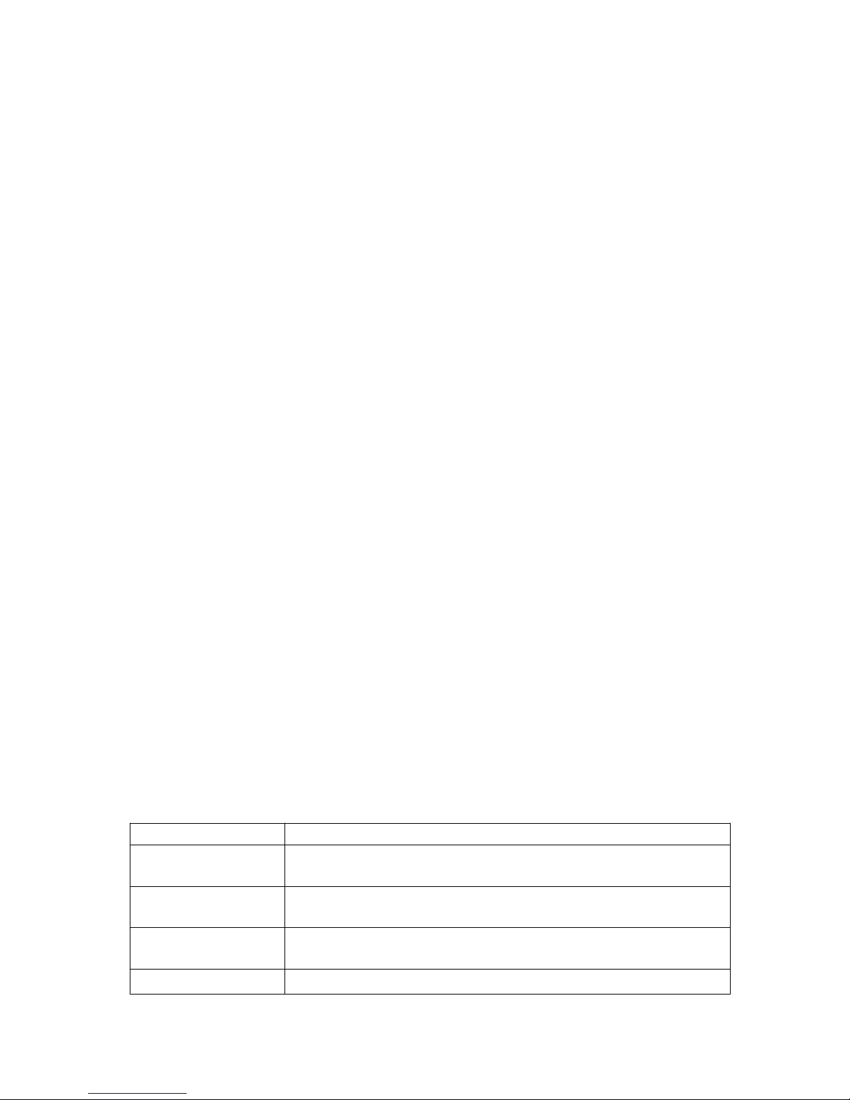
Table 3. Configuration button function
Switch
Description
CONF
long press "1S" button to enter the setting interface, can be used for
selecting different contents( Voltage, frequency, charging current...)
Up SELECT
Up SELECT button can be used for selecting parameter on the function
setting mode
Down SELECT
Down SELECT button can be used for selecting parameter on the function
setting mode
ENTER
Confirm, data save function
Page 14
12
LED Indicator
LED
Description
PV-LED
GREEN LED Lighting on PV normal
Battery-LED
YELLOW LED lighting on Battery normal
AC-LED
GREEN LED lighting on AC Line Mode
INV-LED
GREEN LED lighting on Battery Inverter Mode
Alarm-LED
RED LED lighting on Alarm
Setting Indicators
Table 4. Configuration option
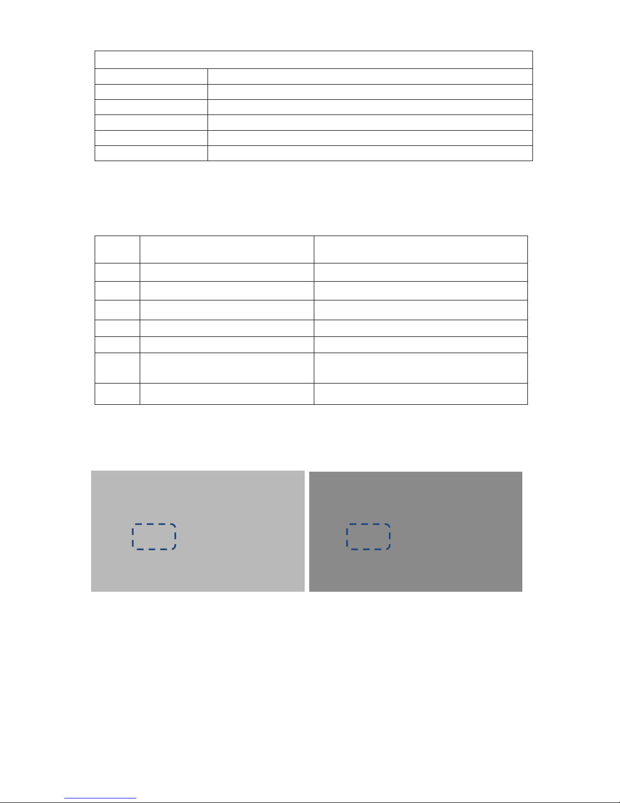
1. Input voltage range Setting
Narrow range mode Wide range mode
NO.
Description
Selectable option
1
Input voltage setting
Wide/Normal.
2
Output voltage setting
208/220/230/240Vac.
3
Output frequency setting
50/60Hz/Automatic.
4
AC charge on, off
AC charge on/AC charge off.
5
AC Charger current setting
20A/35A/50A/70A/90A
6
DC/AC/ Intelligent mode selection
setting
DC mode priority / AC mode priority,
Intelligent mode.
7
DC conversion voltage point setting
11.0Vdc/11.5Vdc/12.0Vdc.
Page 15
13
2. Output voltage Setting
208Vac/220Vac/230Vac/240Vac four kinds of output voltage can be set.
3. Output frequency Setting
50/60Hz frequency output can be adjusted, as well as the adaptive AC input frequency.
Page 16
14
4. AC charger ON/OFF Setting
.5. AC Charger current Setting
Maximum rated charge current can be divided into 5 different stall for adjusting
20A charger can be adjusted into 4A/8A/12A/16A/20A
35A charger can be adjusted into 7A/14A/21/28A/35A.
50A charger can be adjusted into 10A/20A/30A/40A/50A.
70A charger can be adjusted into 14A/28A/42A/56A/70A.
90A charger can be adjusted into 18A/36A/54A/72A/90A.
Page 17
15
6. DC/AC/ Intelligent mode selection setting
AC mode priority DC mode priority
7. Battery capacity setting
Page 18
16
11 kinds of battery capacity settings,
65AH,80AH,100AH,150AH,200AH,250AH,300AH,400AH,500AH,600AH,800AH.
Page 19
17
LCD display meaning
Table 5. display meaning
When inverter is faulty, this sign will appear.
When the inverter enter the setup interface, this flag will appear.
Battery capacity display.
Load capacity display.
Display AC input voltage and frequency, will change to the other info in every 3s.
Display AC output voltage and frequency, will change to the other info in every 3s.
Working mode and fault code.
Battery indicator:
Battery capacity segment will lighting to comply with battery voltage.
Battery
voltage
>26V
25V~26V
24V~25V
23V~24V
21.6V~23V
20V ~21.6V
<20V
ALARM--------
1beep/2s
continue
Load indicator:
The load indicate the load percentage comply with load VA or W (show the bigger value),the overload label will
flash when overload.
Load(±4%)
>85%
65%~85%
45%~65%
25%~45%
0%~25%
Page 20

18
Operating Indicators
AC Mode:
Inverter AC mode, bypass output, mains and battery
indicator light
DC Mode:
Battery inverter mode, inverter output, the inverter
and battery indicator light
PV+DC Mode:
.PV charging battery, battery invert output, PV and
battery mode indicator light.
AC + PV mode:
.AC input and PV charging battery,indicator light.
PV Mode:
Inverter without work, PV charging battery, PV and
battery mode indicator light.
Fault Mode:
Inverter fault. fault indicator light and buzzer alarming
Page 21
19
Table 6 Fault code meaning
Fault code
Fault
Reason and Solution
F01
Over temperature,
fan fault
(alarm light on)
Inverter operate environment is very bad, insufficient ventilation
and indoor temperature is very high. Close the inverter and wait
for 10 minutes, after inverter cool, start again, if fan fault, please
replace with a new fan.
F02
Overload
(alarm light on)
Connecting load power is over than inverter’s rated power, if
reduce the load equipments quantity, inverter will work again.
F03
Output short circuit
(alarm light on)
Close the inverter and disconnect all load equipment, inspect
load equipments if any of them had fault or internal short circuit,
then start the inverter again. If still fault, please consult with
manufacture.
F04
Over temperature
(alarm light on)
Inverter operate environment is very bad, insufficient ventilation
and indoor temperature is very high. Close the inverter and wait
for 10 minutes, after inverter cool, start again.
F05
Low battery voltage
(alarm light on)
Battery damage; Battery deeply discharged, so need to charge
again; battery problem, please replaces the battery. Inverter
charger no work, please consult manufacture.
F06
Reverse input
(alarm light on)
Connect input and output again in correct way.
F07
Semi-wave short circuit
(unusual load)
The connecting load power is over than inverter’s rated power,
after reduce load equipments quantity, inverter will work again.
F08
Over charge
(alarm light on)
Battery type selection incorrect; Charger damage, please consult
manufacture for help.
F09
Battery over voltage
(alarm light on)
Check if battery bank dc voltage is corresponding to this inverter
requested dc voltage.
Page 22
20
SPECIFICATIONS
Table 7. Line Mode Specifications
MODEL
PL201~12KW
Rated power
1 ~ 12KW(230VAC)
1 ~ 6KW(120VAC)
Input Voltage Waveform
Sine wave(Utility or Generator)
Nominal Input Voltage
230Vac
120Vac
Low Line Disconnect
184Vac±4%(NOR)
85Vac±4%(NOR)
135Vac±4%(WID)
80Vac±4%(WID)
Low Line Re-connect
194Vac±4%(NOR)
95Vac±4%(NOR)
145Vac±4%(WID)
85Vac±4%(WID)
Note: 1.NOR setting can be used for general electrical appliance
2. WID setting can be used only for some special load,
Such as lamp, fan.
High Line Disconnect
263Vac±4%(NOR)
136Vac±4%(NOR)
263Vac±4%(WID)
140Vac±4%(WID)
High Line Re-connect
253Vac±4%(NOR)
131Vac±4%(NOR)
253Vac±4%(WID)
135Vac±4%(WID)
Max AC Input Voltage
270VAC
150VAC
Nominal Input Frequency
50Hz / 60Hz (Auto detection)
Low Line Frequency Disconnect
40+0.3Hz for 50Hz, 50+0.3Hz for 60Hz
Low Line Frequency Re-connect
41+0.3Hz for 50Hz, 51+0.3Hz for 60Hz
High Line Frequency Disconnect
55+0.3Hz for 50Hz, 65+0.3Hz for 60Hz
High Line Frequency Re-connect
54+0.3Hz for 50Hz, 64+0.3Hz for 60Hz
Output Voltage Waveform
As same as Input Waveform
Output Short Circuit Protection
Air switch
Efficiency (Line Mode)
>97%
Transfer Time
15ms (typical) 20ms max(WID)
Bypass charger enable in off mode
Yes
Note: NOR – Normal range; WID-Wide range
Page 23
21
Table 8. Invert Mode Specifications
MODEL
HV Model: PL201-12KW
LV Model: PL201-6KW
Output Voltage Waveform
Pure Sine Wave
Rated Output Power
1 ~ 12KW(230VAC)
1 ~ 6KW(120VAC)
Power Factor
0.9 - 1.0
Nominal Output voltage
230Vac
120Vac
Minimum Peak Output Voltage at
Rated Power
>200V
>100V
Output Frequency(Hz)
50Hz / 60Hz ± 0.3Hz
Output Voltage Regulation
±10%
Nominal Efficiency
>87% (@Normal DC Input; >60% R load)
Over-Load Protection
105% <load<150%, beeps 0.5s every 1s, and Fault after 60s.
Load>150%, beeps 0.5s every 1s, and Fault after 20s.
Capable of starting electric motor
YES
Output Short Circuit Protection
Current limit (Fault after 10s), Air switch
Power saver
Load ≦25
±5W
(Enabled on “P/S auto” setting of Remote control
DC voltage
Nominal DC Input Voltage
12VDC
24VDC
48VDC
Min DC start voltage
10.5Vdc
21Vdc
42Vdc
Low DC Alarm
10.5Vdc ± 0.2Vdc
21Vdc ± 0.4Vdc
42.0 ± 0.8Vdc
Low DC Shut-down
10.0Vdc ± 0.2Vdc
20Vdc ± 0.4Vdc
40.0 ± 0.8Vdc
Low DC Shut-down Recovery
11.0Vdc ± 0.2Vdc
22Vdc ± 0.4Vdc
44.0 ± 0.8Vdc
High DC Shut-down
16.0Vdc ± 0.2Vdc
32Vdc ± 0.4Vdc
64.0 ± 0.8Vdc
High DC Shut-down Recovery
15.5Vdc ± 0.2Vdc
31Vdc ± 0.4Vdc
62.0 ± 0.8Vdc
Page 24
22
Table 9. AC Charger Mode Specifications
Nominal Input Voltage
230Vac
120Vac
Input Voltage Range
194V~253Vac(NOR)
160V~253Vac(WID)
95V~131Vac(NOR)
85V~135Vac(WID)
High Voltage Disconnect
253Vac±4%(NOR)
253Vac±4%(WID)
131Vac±4%(NOR)
135Vac±4%(WID)
High Line Re-connect
248Vac±4%(NOR)
248Vac±4%(WID)
128Vac±4%(NOR)
132Vac±4%(WID)
Low Voltage Disconnect
194Vac±4%(NOR)
160Vac±4%(WID)
95Vac±4%(NOR)
85Vac±4%(WID)
Low Line Re-connect
200Vac±4%(NOR)
165Vac±4%(WID)
98Vac±4%(NOR)
88Vac±4%(WID)
Nominal Output Voltage
According to the battery type
Nominal Charge Current
12VDC model: Max 90A
24VDC model: Max 70A
48VDC model: Max 50A
Charge current tolerance
±5A
Over Charge Protection
Bat. V ≥15.5Vdc, Fault, Buzzer alarm for 12Vdc
Bat. V ≥31.0Vdc, Fault, Buzzer alarm for 24Vdc
Bat. V ≥61.0Vdc, Fault, Buzzer alarm for 48Vdc
(beeps 0.5s every 1s & fault after 60s)
Charge Algorithm
Three stage:
Boost CC (constant current stage) → Boost CV (constant voltage
stage) → Float (constant voltage stage)
Note: NOR – Normal range; WID-Wide range
Table 10. Solar Charger Mode Specifications
Rated Battery voltage
12VDC
24VDC
48VDC
Rated charge current
40A
40A
40A
Input voltage range
15-40Vdc
25-55Vdc
50-110Vdc
Max. PV open circuit array voltage
40Vdc
55Vdc
110Vdc
Max. recommended input power (W)
600W
1200W
2350W
Rated Battery voltage
12VDC
24VDC
48VDC
Rated charge current
60A
60A
60A
Input voltage range
15-40Vdc
25-55Vdc
50-110Vdc
Max. PV open circuit array voltage
40Vdc
55Vdc
110Vdc
Max. recommended input power (W)
900W
1750W
3500W
Page 25
23
Table 11. General Specifications
MODEL
PL201-3KW
PL204-6KW
PL208-12KW
Indicators
LED+LCD Display
Protections
Low battery, over charging, over load, over temp.
Remote control
YES
Operating Temperature
Range
0°C ~ 40°C
Storage temperature
-15ºC ~ 60ºC
Operation humidity
5% ~ 95% (non-condensing)
Earthing(ABYC
standard)
Follow customer requirement:
Inverter mode: the neutral and the earth joined ;
Line mode: the neutral and the earth separated.
Use a Relay to realize the function.
Audible Noise
65dB max
Cooling
Forced air, variable speed fan
Size (L*W*H mm)
482.5*336.5*189.5
517.5*396.5*189.5
627.5*416.5*204.5
MODEL
1K
1.5K
2K3K4K5K6K8K10K
12K
Net weight (Kg)
22.0
23.0
24.0
28.0
30.5
35.5
38.5
48.0
55.0
62.0
Product specifications are subject to change without further notice.
Page 26

24
APPENDIX A
How to Select and Configure PV Panels
The following parameters can be found in each PV panel’s specification:
P
max
: Max output power (W)
Voc: open-circuit voltage (V)
Isc: short-circuit current (A)
Vmp: max power voltage (V)
Imp: max power current (A)
PV panels can be connected in series or parallel in order to obtain the desired output voltage and current
which meets the inverter’s allowed range.
When connecting PV panels in series, the max voltage and current of the string is
V
string
= V1+V2+V3+V4…
I
string
= I1=I2=I3=I
4
When connecting the above PV string in parallel, the max voltage and current of the total string is
V
total
= V
string1=Vstring2=Vstring3=Vstring4
…
I
total
= I
string1+Istring2+Istring3+Istring4
In either case, the total output power is P
total
= P
panel
X Number of PV panel
The guideline to select and configure PV string is
P
total
shall be equal or slightly larger than the max. capacity of solar battery charger (900W for 3000VA
model and 2600W for 5000VA model). Surplus capacity of PV string does not help the solar charger’s
capacity and only result in higher installation cost.
Total Vmpof the string shall be within the operating voltage range of solar battery charger (60~72V for
3000VA model and 120~144V for 5000VA model are recommended).
Total Impof the string shall be less than the max. input charging current of the solar battery charger (20A
for 3000VA and 30A for 5000VA model)
Total Vocof the string shall be less than the max. PV input voltage of the solar battery charger (75V for
3000VA and 150V for 5000VA model).
Total Iscof the string shall be less than the max. PV input current of the solar battery charger (20A for
3000VA and 35A for 5000VA model).
Example 1 - How to connect 3000VA model to PV panels with the following parameters?
P
max
: 260W
Voc: 37.7V
Isc: 8.89A
Vmp: 30.9V
Imp: 8.42A
(1) The max. PV input power for 3000VA model is 900W,
900W / 260W = 3.46min. 4 PV panels shall be connected.
(2) Best Operating Voltage Range is 60~72V,
Page 27

25
72V/30.9V = 2.33max. number of PV panel in series is 2.
(3) Max. input charging current is 20A,
20A/8.42A = 2.37
max. number of PV panel in parallel is 2.
(4) Taking (1)~(3) into consideration, the optimized configuration is 2 PV panels in series as a string and
2 strings in parallel, as shown below.
(5) Check again the Vocand Iscof PV string,
Vocof string is 61.8V < 75V (Max. PV Input Voltage)OK
Iscof string is 2 x 8.89A = 17.78A < 20A (Max. PV Input Current)OK
Example 2 - How to connect 5000VA model to PV panels with the following parameters?
P
max
: 260W
Voc: 37.7V
Isc: 8.89A
Vmp: 30.9V
Imp: 8.42A
(1) The max. PV input power for 5000VA model is 2600W,
2600W / 260W = 10min. 10 PV panels shall be connected.
(2) Best Operating Voltage Range is 110~144V,
144V/30.9V = 4.66max. number of PV panel in series is 4.
(3) Max. input charging current is 30A,
30A/8.42A = 3.56
max. number of PV panel in parallel is 3.
(4) Taking (1)~(3) into consideration, the optimized configuration is 4 PV panels in series as a string, and 3
strings in parallel (as shown below).
Page 28

26
(5) Check again the Vocand Iscof PV string,
Vocof string is 4 x 30.9V = 123.6V < 150V (Max. PV Input Voltage) OK
Iscof string is 3 x 8.89A = 26.67A < 30A (Max. PV Input Current) OK
DISPOSAL
In the event the product reaches the end of its service life, please contact the local dealer for disposal
instructions.
The product must not be disposed of with the household
waste.
Disposal of the product at the end of its service life shall be done in accordance with applicable disposal
regulations for electronic waste.
Version:00
614-00020-00
 Loading...