

Page 1

Operating Instructions
863 Valley View Road, Eighty Four, PA 15330 USA
Tel: 724-941-9701 • www.skcinc.com
Sioutas Cascade Impactor
The patented† personal Sioutas Cascade Impactor consists of four impaction stages
and an after-fi lter that allows the separation and collection of airborne particles in
fi ve size ranges. The Sioutas Cascade Impactor is used with the Leland Legacy
Sample Pump (SKC Cat. No. 100-3002) or any other pump capable of maintaining
a constant fl ow rate of 9 L/min. Particles above each cut-point are collected on a
25-mm PTFE fi lter in the appropriate stage. Particles below the 0.25 μm cut-point
of the last stage are collected on a 37-mm PTFE after-fi lter. The Sioutas Cascade
Impactor clips onto a worker’s collar in the breathing zone and the pump clips onto
the worker’s belt. For area sampling, the impactor can be a ached to a tripod or
clipped in an appropriate location. The Sioutas Impactor may be used for ambient
outdoor sampling with special provisions. See Sampling. Size-fractionated samples
can be analyzed gravimetrically, chemically, and microscopically.
† U.S. Patent No. 6,786,105
®
Page 2

Performance Profi le
Flow Rate: 9 L/min
50% Cut-point at 9 L/min: Stage A 2.5 μm
Stage B 1.0 μm
Stage C 0.50 μm
Stage D 0.25 μm
Recommended
After-fi lter Type: (SKC Cat. No. 225-1709)
Recommended Filter
for Stages: 25-mm, 0.5-μm PTFE fi lter* with laminated PTFE
support (SKC Cat. No. 225-3708)
Certification: EPA-ETV has verified the Sioutas Impactor
Wind Velocity: < 5 mph
After-fi lter Operating
Temperature (maximum): 464 F (240 C) based on PMP support ring
Maximum Particle Load: Varies per stage. See NUATRC Report No. 2 at
www.sph.uth.tmc.edu/mleland/a achments/
MLeland_Sioutas2.pdf.
Impactor Material: Inlet/oulet plates and stages are anodized
autoclavable aluminum; O-rings are Buna-N
(Nitrile); fi lter retainers are acrylic; compression
ring is PTFE
Inlet and Outlet Inlet: 3/8-in OD, 1/4-in ID
Diameters: Outlet: 3/8-in OD, 1/4-in ID
Dimensions: 3.4 x 2.2 in (8.6 x 5.6 cm)
Weight: 5.6 oz (159 gm)
37-mm, 2.0-μm PTFE fi lter* with PMP support ring
performance with the Leland Legacy sample
pump. See h p://archive.epa.gov/nrmrl/archive-etv/
web/pdf/vs_skcsioutas.pdf for details.
Tubing: 3/8-in ID
* Back pressure on PTFE fi lters can vary within the same lot.
2
Page 3

Disassembly
1
4
The Sioutas Impactor will arrive already assembled with the exception of the fi lter
retainers, which are included, but packaged separately. Disassemble it to clean
(see Cleaning), to load with filters (see Assembly), or to remove filters after
sampling.
Disassemble the impactor from inlet to outlet. See Figure 1 and follow Steps 1-7.
Thumb
nuts
Inlet
plate
Clip
Figure 1. Sioutas Impactor, exploded view
Remove thumb nuts.
Accelerator plate A
Accelerator plate B
Collector plate
Accelerator plate C
Collector plate
Accelerator plate D
Collector plate
Remove inlet plate.
Collector plate
Threaded
studs
Outlet
plate and
after-fi lter
housing
Lift off together accelerator plate A and
collector plate.
Lift accelerator plate A off
collector plate.
3
Page 4
567
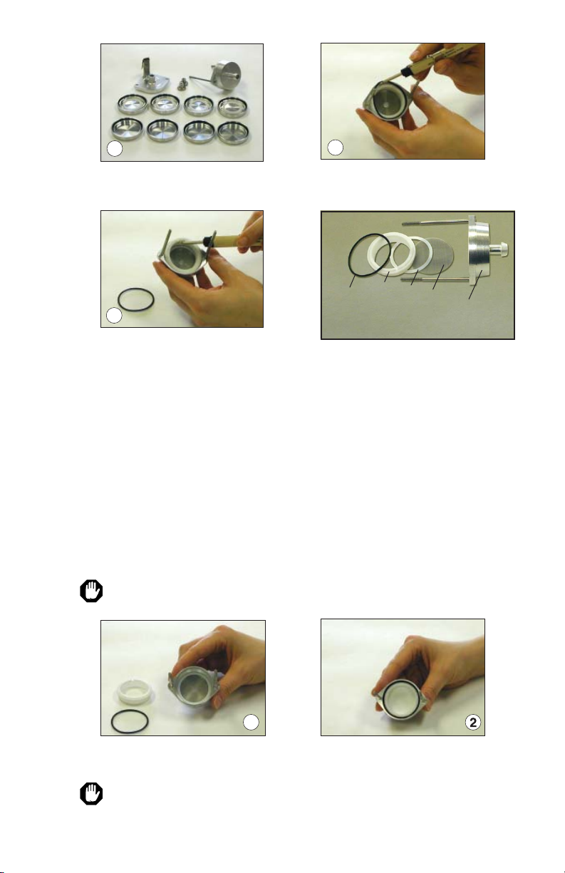
Repeat Steps 3 and 4 for stages B-D.
1
Remove O-ring from outlet plate.
See Figure 2.
Remove compression ring from outlet
plate. See Figure 2.
O-ring
ring
Spacer ring
Compression
Figure 2. Outlet plate, exploded view
Screen
Outlet
plate
Note: Use forceps to carefully insert or remove impaction substrate, after-fi lter,
and fi lter retainers.
Media and Impactor Preparation
Equilibrate and pre-weigh the fi lters in a clean environment according to appropriate
procedures. Record the weight as the pre-sample weight.
Clean the Sioutas Impactor in between samples to remove any residual particles.
See Cleaning.
Assembly
In a clean environment, assemble the Sioutas Impactor from outlet to inlet as
follows:
Caution: Handle all fi lter material with forceps.
Remove O-ring and compression ring
from outlet plate. See Disassembly,
Steps 6 and 7 and Figure 2.
Insert 37-mm after-fi lter in outlet plate.
Replace compression ring and O-ring.
Ensure that the screen and spacer ring (Figure 2) are in place before inserting
fi lter. The screen prevents the fi lter from restricting the outlet.
4
Page 5

3
4
Align
5
6
7
marks
Filter
Nest a collector plate in top of outlet
plate. Align the marks.
Filter
retainer
Filter
Use forceps to place a fi lter retainer on
top of the fi lter. Press down fi rmly
until snug.
Use forceps to place a 25-mm fi lter in
collector plate.
Align
“D” with
mark
Place accelerator plate D (O-ring
side up) on top of collector plate.
Align “D” with mark.
Note: Tighten thumb nuts using an
alternating pa ern. It is important
to the operation of the impactor to
tighten the thumb nuts completely.
Repeat Steps 3 through 6 for stages C-A,
slide inlet plate into place, and screw on
thumb nuts.
One, Two, or Three-stage Sampling
Place desired number of loaded stages (accelerator and collector plate pairs) onto the
outlet plate. Replace the inlet plate, replace and tighten the thumb nuts, calibrate,
and sample.
5
Page 6

Calibration
Calibrate pump fl ow rate with the Sioutas Impactor and representative after-fi lter
in place. It is not necessary to pre or postweigh representative media. You may also
calibrate with representative fi lters in all the stages if desired, however, it is not
necessary for proper calibration.
1. Using fl exible tubing, connect the outlet of the Sioutas Impactor to the inlet of a
Leland Legacy Sample Pump or other pump capable of maintaining a constant
9 L/min fl ow rate.
2. Connect the inlet of the Sioutas Impactor to the outlet of a calibrator capable of
calibrating 9 L/min.
Sioutas Impactor in calibration train with Leland Legacy Pump and TSI 4146 Calibrator
3. Calibrate the sample pump to 9 L/min. See calibrator and pump operating
instructions.
6
Page 7

Sampling
• As the particle load on the after-fi lter increases during sampling, the pressure drop will
also increase. Therefore, use a compensating sample pump such as the Leland Legacy
(SKC Cat. No. 100-3002).
• Back pressure on PTFE fi lters can vary within the same lot.
• The Sioutas Impactor may be used for ambient outdoor sampling with the following
provisions:
1. Wind velocity is < 5 mph.
2. The impactor plates are not overloaded. See NUATRC Report No. 2 at
www.sph.uth.tmc.edu/mleland/attachments/MLeland_Sioutas2.pdf for
information on maximum particle load per stage.
1. Following calibration, remove and set aside the
representative sample media. Replace with new,
preweighed media. See Media and Impactor
Preparation and see Assembly.
2. Turn on the pump and record sample start time
and other pertinent data.
3. After the desired sample time has elapsed, turn
off the pump and record sample stop time.
4. Remove pump and tubing. Transport samples and
pertinent sampling information to a laboratory for
analysis. See Removing and Transporting the Samples.
Sioutas Impactor in
sampling train
Removing and Transporting the Samples
Disassemble the stages. See Disassembly. Using forceps, carefully remove fi lters
for weighing and analysis. If transporting samples to an off site laboratory, place
samples in marked, sealed containers and transport.
Clearly indicate on sample containers and chain-of-custody forms the stage from
which each fi lter was removed.
Package and transport samples in a manner that will prevent sample loss and
contamination.
Analysis
Size-fractionated gravimetric, chemical, and microscopic analyses
7
Page 8

Cleaning
Clean the Sioutas Impactor in between samples to remove residual particles.
Disassemble all stages (see Disassembly) and O-rings. To remove O-rings, align the
head of a small fl at-head screwdriver with the notch in the inner wall of the plate.
Gently lift the O-ring up and out. Wash all parts except fi lter retainers either in
water with detergent or in isopropyl alcohol. Wash fi lter retainers only in water
with detergent. Parts may also be cleaned in an ultrasonic bath. Rinse and dry all
parts thoroughly with compressed air if available. Otherwise, air dry in a clean
environment. Inspect all accelerator plates by holding them up to a light to ensure
that none of the impaction slits are clogged. Impaction slits may be cleaned with
compressed air.
Do NOT use any mechanical object to clear an obstruction from a clogged
impaction slit.
Tips
• Additional collector plates can be loaded and ready to use when sampling
at multiple sites. See Accessories for ordering replacement collector plates.
• Handle all fi lter material and fi lter retainers with forceps. See Accessories for
ordering forceps.
• The Sioutas Impactor may be used for ambient outdoor sampling with the
following provisions:
1. Wind velocity is < 5 mph.
2. The impactor plates are not overloaded. See NUATRC Report No. 2
at www.sph.uth.tmc.edu/mleland/a achments/MLeland_Sioutas2.pdf for
information on maximum particle load per stage.
8
Page 9

Ordering Information
Description Cat. No.
Sioutas Personal Cascade Impactor 225-370
Pump for Sioutas Impactor Cat. No.
#
Leland Legacy Sample Pump,
5 to 15 L/min, with Li-Ion battery pack,
CE marked 100-3002
Filters for Sioutas Impactor Cat. No.
After-fi lter, 37 mm PTFE*
‡
with PMP support ring, 2.0 μm, pk/50, optional 225-1709
Collection Substrate (fi lter for 4 stages), 25-mm PTFE* with PTFE support,
0.5 μm, pk/250, required 225-3708
* Back pressure on PTFE fi lters can vary within the same lot.
‡ Maximum operating temperature is 464 F (240 C) based on PMP support ring.
# Use in non-explosive environments only, not UL Listed for intrinsic safety
Accessories Cat. No.
Tubing, Tygon, 3/8-inch ID, fi ts Sioutas Impactor and Leland Legacy pump,
10 feet 225-1351
Replacement Collector Plates, set of 4 P55016
Ring/Spacer Set includes 4 fi lter retainer rings, 9 O-rings, 1 PTFE spacer ring P51917
Filter Retainers only, pk/4 P20151
Forceps, precision stainless steel with serrated tips for inserting fi lters 225-13-1
Development
Developed by Dr. Constantinos Sioutas of the University of Southern California in
partnership with the Mickey Leland National Urban Air Toxics Research Center
(NUATRC).
References
Misra, C., Singh, M., Shen, S., Sioutas, C., and Hall, P., “Development and Evaluation of a Personal
Cascade Impactor Sampler (PCIS),” Journal of Aerosol Science, 33, 2002, pp. 1027-1047
Ono-Ogasawara, M., Myojo, T. “A Proposal of Method for Evaluating Airborne MWCNT
Concentration,” Industrial Health, 49, 2011, pp. 726-734
Ono-Ogasawara, M., Myojo, T., “Characteristics of multi-walled carbon nanotubes and background
aerosols by carbon analysis; particle size and oxidation temperature,” Advanced Powder
Technology, 2012, http://dx.doi.org/10.1016/j.apt.2012.06.013
Singh, M., Misra, C., Sioutas, C., “Field Evaluation of a Personal Cascade Impactor Sampler
(PCIS),” Atmospheric Environment, 37, 2003, pp. 4781-4793
Sioutas, C., “Development of New Generation Personal Monitors for Fine Particulate Matter (PM)
and its Metal Content,” NUATRC Research Report No. 2, 2004, www.sph.uth.tmc.edu/mleland/
attachments/MLeland_Sioutas2.pdf
SKC Limited Warranty and Return Policy
SKC products are subject to the SKC Limited Warranty and Return Policy, which
provides SKC’s sole liability and the buyer’s exclusive remedy. To view the complete
SKC Limited Warranty and Return Policy, go to h p://www.skcinc.com/warranty.
9
Page 10

101112
Page 11

Page 12

www.skcinc.com
Form 40086 Rev 1902
 Loading...