

Operating Instructions
SKC Deployable Cartridge
Sampler (DCS) System
SKC Inc.
863 Valley View Road
Eighty Four, PA 15330
Form #38048 Rev 1008

DCS System Quick Guide
Sampling Head and Cartridge Installation
1. Disassemble sampling head: Unscrew inlet from cartridge holder section. Unscrew
cartridge holder section from exhaust section. Clean parts and allow to dry.
2. Thread cartridge holder section onto exhaust section.
3. Insert cartridge into cartridge holder (arrow pointing toward exhaust).
4. Reinstall inlet section onto cartridge holder section.
Setup and Calibration
1. Set up sample pump. (See Leland Legacy
programming, see Leland Legacy Operating Instructions.)
2. Ensure cartridge is installed in sampling head.
3. Thread calibration adapter into sampling head inlet.
4. Use tubing with quick-connect fi tting to connect pump inlet to outlet of sampling head.
5. Use short tubing to connect inlet of calibration adapter to outlet of calibrator.
6. Calibrate pump fl ow rate to 10 L/min and record the pre-sample fl ow rate.
7. Disconnect calibrator and remove calibration adapter from sampling head.
8. Mount bracket at desired location.
9. Install sampling head on mounting bracket.
10. Install rain cover on sampling head.
®
Quick Guide on page 9. For advanced
Sampling
1. Turn on pump and record pertinent data. (Leland Legacy pump may be started
manually or automatically, see Quick Guide on page 9.)
2. After desired sampling period, record sample stop time. Remove rain cover. Reinstate
calibration train to verify pump fl ow rate. Record post-sample fl ow rate.
3. Turn off pump. Record pertinent information.
4. Remove sampling head: Use quick-connect to detach tubing from pump inlet. Remove
tubing from sampling head. Remove sampling head from bracket. Move sampling head
to a clean area.
Sample Removal
1. Disassemble sampling head: Unscrew inlet from cartridge holder section.
2. Lift cartridge from cartridge holder section, wrap in aluminum foil, and place in supplied
PTFE jar. Transport to lab.
SKC Inc., 863 Valley View Road, Eighty Four, PA 15330 • www.skcinc.com
Pre3

Table of Contents
Introduction ............................................................................................1
Performance Profi le ...............................................................................2
Principle of Operation ............................................................................3
Media Preparation .................................................................................4
Cartridge Preparation ............................................................................4
Deployment of Cartridges for Field Sampling ............................................................ 5
Sampling Head Preparation ..................................................................5
Cleaning the Sampling Head ..................................................................................... 5
O-ring Care for the Sampling Head ...........................................................................5
Inserting a Cartridge into the Sampling Head ...........................................................6
Sample Pump Operation .......................................................................7
Charging the Battery .................................................................................................7
Reading the Charging Status LED ............................................................................ 8
Battery Setup ............................................................................................................. 8
Battery Replacement .................................................................................................8
Leland Legacy Quick Guide ...................................................................................... 9
Calibration and Sampling ....................................................................10
Calibration ...............................................................................................................10
Sampling .................................................................................................................11
Sample Removal, Shipping, and Analysis ...........................................12
Removing the Cartridge from the Sampling Head ................................................... 12
Transporting Samples ............................................................................................. 12
Sample Storage ....................................................................................................... 12
Removing Filter and Sorbent from Cartridge ........................................................... 13
Analysis ...................................................................................................................13
Ordering Information............................................................................14
Li-Ion Battery Shipment .......................................................................15
Warranty ..............................................................................................15
Indicates a reminder or note
Indicates a warning or caution
Pre5
INTRODUCTION
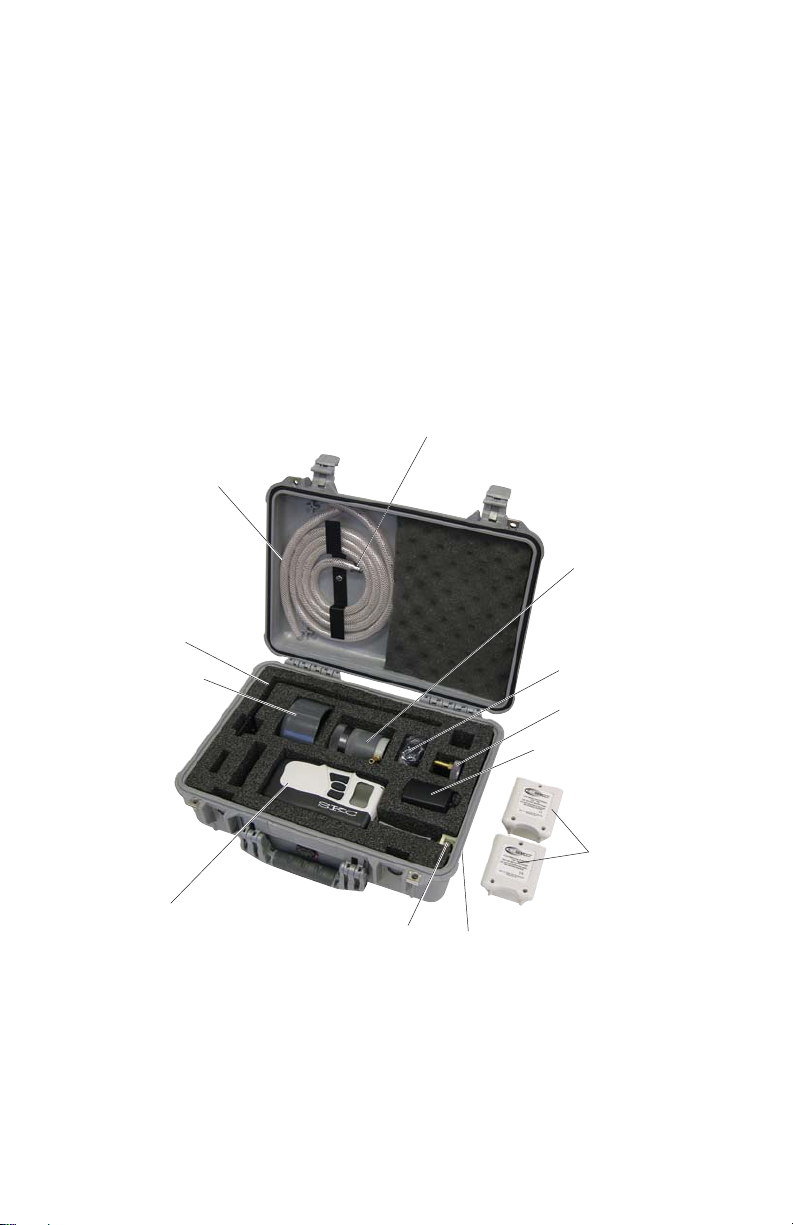
The SKC Deployable Cartridge Sampler (DCS) System is a compact, portable,
and ba ery-operated sampling system that ensures the ability to sample gaseous
polycyclic aromatic hydrocarbons (PAHs), polyhalogenated dibenzo-p-dioxins
(PHDDs), and polyhalogenated dibenzofurans (PHDFs) and particulate-associated
PHDDs and PHDFs in ambient air. The system features the fully programmable
constant fl ow Leland Legacy Sample Pump and an easy-to-use sampling head
that houses a stainless steel cartridge. The cartridge can be loaded with a 47-mm
quartz fi lter and PUF (EPA TO-9A) or XAD
deployed system is packaged in a portable heavy-duty Pelican
the system operates.
quick-connect fi tting
Calibration tubing
Mounting
bracket
Rain cover
®
-2 sorbent (EPA TO-13A). The easily
Tubing with
®
case from which
Sampling head
Worldwide plugs
for charger
Calibration adapter
Charging unit and
power supply
External battery
assemblies
with battery
Leland Legacy
pump with
connection
cable
The SKC DCS System includes a Leland Legacy Sample Pump with connection case and cable,
charger (100-240 V), sampling head, calibration adapter, rain cover, sample tubing with quick-connect
fi ing, calibration tubing, and mounting bracket in a heavy-duty lockable carry case. Two external
ba ery assemblies with adapters are packaged separately. Cartridges, fi lters, and sorbent media
are available separately.
Quick-connect
release
Quick-connect plug
(not shown)
adapters (2)
1

PERFORMANCE PROFILE
Flow Rate: 10 L/min
Run Time: > 24 hrs on one battery charge
Power: Rechargeable lithium-ion (Li-Ion) battery, 7.4 V,
12-Ah capacity
Battery Recharge Time: 15 hrs
Pre-fi lter: 47-mm quartz, QM-A, 450-μm thickness
(Not supplied with system)
Sorbent: EPA TO-9A: PUF (polyether type), 40-mm diameter, cleaned
(Not supplied with system) or
EPA TO-13A: XAD-2 sorbent, cleaned
Analysis: TO-13A: Gas chromatography/mass spectrometry (GC/MS)
TO-9A: High resolution gas chromatography/High resolution
mass spectrometry (HRGC/HRMS)
Tubing: 3/8-in ID reinforced fl exible PVC (supplied)
Temperature: Charging: 32 to 113 F (0 to 45 C)
Operating: 32 to 113 F (0 to 45 C)
Storing: -4 to 95 F (-20 to 35 C)
Altitude: Do not use pump beyond 7500 ft.
RFI/EMI Shielding: CE marked
Case Dimensions: 18.5 x 14.1 x 6.9 in (47 x 36 x 18 cm)
Complete System Weight: 12.20 lbs (5.5 kg)
Sampling Head
Dimensions: 2.6 dia. x 3.6 H x 3.8 L in (7 x 9 x 10 cm)
Sampling Head Weight: 0.60 lb (.27 kg)
(without cartridge)
Cartridge Weight: 0.75 lb (.34 kg)
†
, 88.8 Wh
† DCS Systems contain Li-Ion ba eries and may be subject to special shipping
regulations dependent upon quantity.
2
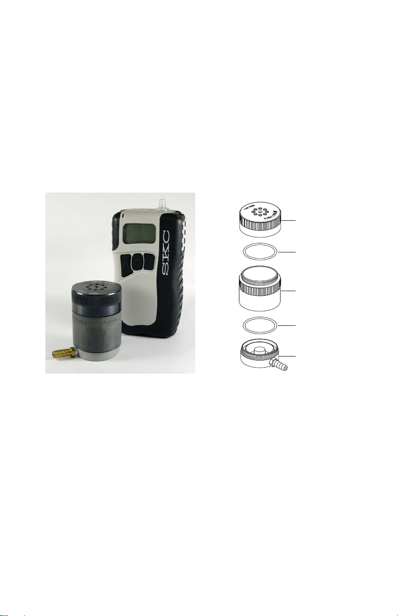
PRINCIPLE OF OPERATION
A sample pump draws air at a fl ow rate of 10 L/min through nozzles on top of
the sampling head and into the cartridge. The cartridge is designed to be loaded
with a cleaned 47-mm quartz fi lter that collects particles and cleaned PUF or
XAD-2 sorbent that adsorbs gases and vapors. The aluminum foil-wrapped
cartridge is supplied in a PTFE jar so that the sample is protected from light and
contamination during transport. The fi lter and sorbent media are combined for
extraction followed by GC/MS analysis for EPA TO-13A or HRGC/HRMS for
EPA TO-9A.
Inlet section
PTFE O-ring
Cartridge holder
section
BUNA-N O-ring
DCS Sample Head and
Leland Legacy Sample Pump -
the two main components of
the DCS System
Exhaust section
Exploded view of the
DCS Sample Head
3

MEDIA PREPARATION
For Laboratory Use
Use clean hexane-rinsed PTFE-tipped forceps to handle fi lters.
Wear disposable, clean, lint-free nylon or powder-free surgical gloves
to handle the sorbent and cartridge.
Quartz Filter: Prepare following the procedure outlined in EPA TO-9A or
TO-13A, Section 10.2.1. (h p://www.epa.gov/ namti1/airtox.html)
XAD-2 Sorbent: Purchase precleaned or use procedure outlined in EPA TO13A, Section 10.2.5.
PUF: Purchase precleaned or use procedure outlined in EPA TO-9A or TO-13A,
Section 10.2.4.
CARTRIDGE PREPARATION
For Laboratory Use
Use clean hexane-rinsed PTFE-tipped forceps to handle fi lters.
Wear disposable, clean, lint-free nylon or powder-free surgical gloves
to handle the sorbent and cartridge.
1. Rinse cartridge with appropriate organic solvent and allow to dry.
2. Ensure PTFE gasket 1, the stainless steel support screen 1, and PTFE
gasket 2 are in place on bo om cartridge cap.
3. Insert PUF or XAD-2 into the cartridge.
4. Ensure the PTFE gasket 3 and stainless
steel screen 2 are in place on cartridge
body top.
5. Using cleaned forceps, align quartz fi lter
with screen radially, and place PTFE
gasket 4 on top of fi lter. Thread top
cartridge cap onto cartridge.
6. Wrap the cartridge with hexane-rinsed
aluminum foil, place in supplied PTFE
jar, and label jar. Analyze (certify) at least
1 cartridge from each batch of cartridges
prepared using the procedure described
in Section 10.3 of EPA TO-9A or EPA
TO-13A (h p://www.epa.gov/ namti1/
airtox.html) prior to fi eld use. See Section
10.3.8 for acceptable background levels.
Cartridges are considered clean for up to
30 days from date of certifi cation when
sealed in their containers.
4
Insert
47-mm
t
fi lter
Insert
PUF or
t
XAD-2
sorbent
Cartridge for EPA TO-13A
Top
cartridge cap
PTFE gasket 4
Stainless steel
support screen 2
PTFE gasket 3
Stainless steel
cartridge body
PTFE gasket 2
Stainless steel
support screen 1
PTFE gasket 1
Bottom
cartridge cap

Deployment of Cartridges for Field Sampling
Immediately prior to fi eld deployment, follow the procedure in EPA TO-9A or
TO-13A, Section 10.4.
SAMPLING HEAD PREPARATION
Cleaning the Sampling Head
All cleaning, loading, and unloading should be conducted in a controlled
environment to minimize any chance of potential contamination. When new
or when using the sampler at a diff erent location, all sample contact areas need
to be cleaned. Rinse with appropriate organic solvent. Allow the solvent to
evaporate before loading a cartridge.
For deployed applications where method-specifi ed solvents are
unavailable, use isopropyl (rubbing) alcohol or a clean tissue wipe.
Do not place any mechanical object in the inlet nozzles.
O-ring Care for the Sampling Head
Visually inspect the condition of the BUNA-N exhaust O-ring (see illustration
on page 3 for location). Ensure the O-ring surface is smooth (i.e., without cracks,
cuts, or other damage). Ensure the O-ring is fi ed properly in its channel.
Replace the exhaust O-ring if there is apparent damage, stretching, or thinning.
It is recommended that the PTFE inlet O-ring be replaced by the manufacturer
only.
5

Inserting a Cartridge into the Sampling Head
4
1
Wear disposable, clean, lint-free nylon or powder-free surgical gloves
to handle the sorbent and cartridge.
1. Disassemble sampling head (see drawing
on page 3 for placement of parts).
a. Unscrew inlet section from cartridge
holder section.
b. Unscrew cartridge holder section
from exhaust section.
Clean and allow to dry (see Cleaning the
Sampling Head on page 5).
2. Thread cartridge holder section onto
exhaust section.
3. Remove cartridge from aluminum foil
and insert into cartridge holder section.
Ensure airfl ow arrow on cartridge points
to exhaust section. The fi lter should be on
the inlet side of the cartridge.
Cartridge
Inlet
section
Disassemble sampling head.
Thread cartridge holder onto
exhaust section.
holder
section
Exhaust
section
Insert cartridge into cartridge
holder section.
4. Thread inlet section onto cartridge
holder section until just tight. Further
hand-tighten by 1/4 turn only.
Thread inlet section onto cartridge
holder section.
6

SAMPLE PUMP OPERATION
1
The user may choose to:
• Operate the pump manually in the fi eld (on/off )
• Program a schedule into the pump manually
• Program the pump for multiple schedules from a PC
with optional DataTrac
(see Ordering Information, Accessories on page 14).
See page 9 for a Quick Guide to operate the SKC Leland
Legacy Sample Pump. For advanced programming, see the
complete Leland Legacy Pump Operating Instructions.
Charging the Battery
Completely charge a new ba ery pack using the SKC-approved charger (Cat. No.
223-241) before operating the pump. It may be necessary to charge the ba ery a
few times before maximum ba ery capacity is achieved.
Cautions:
• Do not charge or operate pump with or without charger in hazardous
locations.
• Use only the SKC-approved charger for this pump. Use of an
unapproved charger may damage the ba ery and pump.
• Use of a non-approved charger voids any warranty.
• Do not open, disassemble, short circuit, crush, incinerate, or expose the
ba ery to fi re or high temperatures.
• Tampering with the ba ery pack voids any warranty.
• Ensure proper orientation of charging cable before plugging it into the
charging jack. Improper orientation/contact will short-circuit the ba ery
and voids any warranty.
• Short-circuiting the ba ery pack will render it immediately inoperative.
• Failure to follow warnings and cautions voids any warranty.
®
for Leland Legacy So ware
The ba ery pack may be kept on the SKC-approved charger for an
indefi nite time.
1. Insert the plug from the charging unit into the
charging port on the ba ery adapter (on top of the
external ba ery assembly).
2. Insert plug from power supply into the jack on the
charging unit.
Battery
adapter
External
battery
assembly
Charging
unit plug
3. Install the appropriate wall plug on the power
supply and plug power supply into a wall outlet.
The ba ery will recharge in approximately 15
hours. For a complete charge, do not run the pump
Power
supply
Charging
unit
External
battery
assembly
connected to the external ba ery assembly during
charging. A er charging is complete, disconnect
7
ba ery from charger and connect pump to ba ery (see Ba ery Setup below).
1
A er charging the ba ery pack, it is good practice to run the pump for
approximately 5 minutes before calibrating. This ensures the ba ery is
in more steady-state conditions and improves the agreement in pre and
post-sampling calibrations.
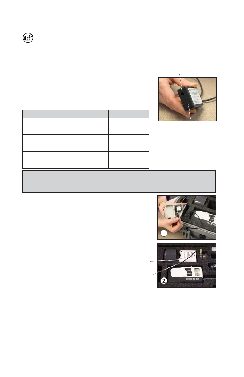
Reading the Charging Status LED
Power supply jack
The Li-Ion Charging Unit indicates ba ery charge
status via an LED on the unit that blinks in specifi c
pa erns. Observe the LED steadily for > 5 seconds
to read charge status.
LED Action Charge Status
ON
Ò
2 sec
OFF
{
2 sec
OFF
{
.25 sec
ON
Ò
.25 sec
ON
Ò
steady
ON
(Repeats) Approximately
Ò
2 sec
OFF
(Repeats) Charge completed
{
2 sec
Charge in progress
80% charged
Charge status LED
For more information on SKC pump batteries, go to http://www.skcinc.
com/instructions/1756.pdf.
Battery Setup
1. Insert the plug on connecting cable from pump
into the jack on the ba ery adapter (on top of
the external ba ery assembly).
2. Insert external ba ery assembly into a foam
compartment in the case. Ensure there is no
tension on the connecting cable.
External battery
assembly
Connecting cable
Battery Replacement
1. Record all necessary data before unplugging pump from ba ery.
2. Remove plug on connecting cable from jack on ba ery adapter (on top of
the external ba ery assembly).
3. Insert plug on connecting cable into ba ery adapter jack on new, fully
charged external ba ery assembly.
4. Insert external ba ery assembly into foam compartment in case. Ensure
there is no tension on the connecting cable.
8

Leland Legacy Quick Guide
Terms »
Star button Ò
• Scrolls through run time data and Setup options
Up and down arrow buttons ST
• Toggle between display choices and increase or decrease sampling parameters in Setup
Button sequence
T Ò= press buttons individually
[ST] = press simultaneously
ÒSTÒ = security code, always press in sequence
Security code ÒSTÒ
• Prevents unauthorized changes to the pump’s sampling program
Programming Sequences »
• To activate pump (e.g., to change pump from Sleep to Hold):
Press any button.
• To change pump from Hold to Run or Run to Hold:
Press [ST].
• To reset accumulated data:
Press [ST], then ÒSTÒ. Press Ò until CLr displays then press [ST]; press Ò until End displays then
press [ST].
• To set pump fl ow rate:
Press [ST], then ÒSTÒ. Flow rate and SET fl ash. Press S or T to change fl ow rate. Press Ò until End
appears then press [ST] to save setting and place pump in Hold.
• To calibrate fl ow rate with standard calibrator:
Press [ST], then ÒSTÒ. Flow rate and SET fl ash. Press S or T to change fl ow rate. Press Ò once. ADJ
displays. Press S or T until desired fl ow rate is indicated on calibrator. When fi nished, press Ò until End displays
then press [ST] to save new setting and place pump in Hold. For CalChek Calibration, see operating instructions.
• To change temperature scale from F to C or C to F:
Press [ST], then ÒSTÒ. Press Ò until temperature displays. Press S or T to switch units; press Ò until
End displays then press [ST] to save new setting.
• To change atmospheric pressure scale (mm, mb, In):
Press [ST], then ÒSTÒ. Press Ò until pressure displays then press S or T to switch units; press Ò until
End displays then press [ST] to save new setting.
• To change time scale (12 Hr/24 Hr/Dela):
Press [ST], then ÒSTÒ. Press Ò until 12 Hr, 24 Hr, or Dela displays then press S or T to switch units;
press Ò until End displays then press [ST] to save new setting. To set delayed start (Dela), see operating
instructions.
• To change clock:
Press [ST], then ÒSTÒ. Press Ò until clock displays then press S or T to change fl ashing hour; press Ò to
move to minutes and S or T to change setting. Press Ò until End displays then press [ST] to save new setting.
• To change the sampling time function:
Press [ST], then ÒSTÒ. Press Ò until ST L/min displays then press S to change fl ashing digit; press Ò
End displays then press [ST] to save new setting. To delete, follow above steps and press T until 0 appears.
Exit Setup.
Note: When in Setup, choosing Esc instead of End will exit Setup without saving new settings.
until
SKC Inc., 863 Valley View Road, Eighty Four, PA 15330 • www.skcinc.com
9

CALIBRATION AND SAMPLING
1
Calibration
Calibrate pump fl ow rate with the sampling head loaded with a cartridge in
line. See pump and calibrator operating instructions.
Wear disposable, clean, lint-free nylon or powder-free surgical gloves to
handle the sorbent and cartridge.
Ensure pump has run for 5 minutes
before calibrating. Ensure rain
cover is removed from inlet and
that sampling head is completely
assembled with a fully loaded
cartridge (see Inserting a Cartridge
into the Sampling Head).
Thread calibration adapter into
sampling head inlet.
Inlet line
to pump
Inlet
Quick-
connect
plug
Unscrew quick-connect plug on side of case. Use tubing with quick-connect
fi ing to a ach case (pump) inlet to exhaust of sampling head.
Ensure O-ring is installed on the quick-connect fi ing before inserting it
into the inlet. Absence of the O-ring can aff ect measurements. See page 14
for Replacement Parts.
Quick-
connect
fi tting on
tubing
Use provided short length of calibration tubing to connect inlet of calibration
adapter to outlet of a calibrator to form a calibration train.
Inlet to
Calibration adapter
pump
Set and calibrate pump fl ow rate to 10 L/min (see Leland
Legacy Quick Guide on page 9). Record the pre-sample fl ow
rate. See pump and calibrator operating instructions.
Sample
head
outlet
Flowmeter
outlet
10
When calibration is completed,
disconnect calibrator and tubing
from calibration adapter. Remove
calibration adapter from sampling
head.

Sampling
1
3
6
Locate system in an unobstructed area, at least 6 feet (2 meters) from
any obstacle to airfl ow.
Wear disposable, clean, lint-free nylon or
powder-free surgical gloves to handle the
sorbent and cartridge.
Before use, allow pump to equilibrate a er
moving it from one temperature extreme to
another.
1. A ach mounting bracket at the desired location
and at breathing zone height (6 feet or 2 meters)
using wire ties or other fasteners. Mount sampling
head loaded with cartridge on mounting bracket by
threading clamp knob into bo om of sampling head.
2. Insert screw on rain cover into top of the sampling
head inlet and rotate cover until tight.
3. Turn on pump and record sample start time, ambient
temperature, ambient pressure, and other pertinent
data.
Sample start time and duration can be programmed into the Leland Legacy Sample Pump
in advance and sampling may be started manually or automatically.
Record all necessary data before disconnecting
pump from ba ery and reconnecting to new
ba ery.
4. A er desired sample time has elapsed, record sample stop time. Remove
rain cover from sampling head and reinstate calibration train (see
Calibration on page 10). Record post-sample fl ow rate.
5. Turn off pump. Record total volume, ambient temperature, ambient
pressure, and other pertinent data.
6. Reach inside case and press quick-connect
release while pulling tubing from case (pump)
inlet. Remove tubing from sampling head.
Quick-connect
release inside
case
Remove sampling head from bracket.
7. Remove sampling head to a clean area.
Technical Tidbits
• The supplied rain cover should be used for all
Press quick-connect release to
remove tubing.
Tubing with
quick-connect
fi tting
outdoor sampling.
• Keep Leland Legacy Sample Pump inside the Pelican case and the case
closed during sampling to protect sample pump from weather.
11

SAMPLE REMOVAL, SHIPPING, AND
1
3
ANALYSIS
Removing the Cartridge from the Sampling Head
Wear disposable, clean, lint-free nylon or powder-free surgical gloves
to handle the sorbent and cartridge.
1. Unscrew inlet section from cartridge
holder section.
Ensure cartridge remains vertical to
avoid loss of sample from fi lter.
Remove inlet section
from cartridge holder section.
2. Li cartridge from cartridge holder
section.
Li cartridge from cartridge
holder section.
3. Wrap cartridge in supplied foil or clean
aluminum foil and place in supplied
PTFE jar to protect sample from light and
contamination.
Wrap cartridge in foil and
insert in PTFE jar.
Transporting Samples
Package and transport samples and blanks under ice (< 39.2 F [4 C]) until
receipt at the analytical laboratory.
Sample Storage
Store samples under ice (< 39.2 F [4 C]) in the fi eld or at < 39.2 F (4 C) in a re-
frigerator in the laboratory. Extraction must be performed within seven days of
sampling and analysis within 40 days a er extraction.
12

Removing Filter and Sorbent from Cartridge
For Laboratory Use Only
1. Remove fi lter and sorbent(s) from cartridge.
2. Combine for extraction.
3. a. For XAD-2 sorbent: Use procedure outlined in EPA TO-13A,
Section 12.2.
b. For PUF sorbent: Use procedure outlined in EPA TO-9A,
Section 12.1.
Analysis
TO-13A: Gas chromatography/mass spectrometry (GC/MS)
TO-9A: High resolution gas chromatography/High resolution mass
spectrometry (HRGC/HRMS)
13
ORDERING INFORMATION
Description Cat. No.
DCS System
case and cable, charger (100-240 V), 2 external battery assemblies,
sampling head, calibration adapter, rain cover for sampling head, sample
tubing with quick-connect fi tting, calibration tubing, and mounting bracket
in a heavy-duty lockable carry case. Two external battery assemblies
with adapters are packaged separately. Cartridges, fi lters, and sorbent
media available separately 100-3960
† DCS Systems contain Li-Ion batteries and may be subject to special shipping regulations dependent
upon quantity.
# Use in non-explosive environments only. Not UL Listed for intrinsic safety
DCS Cartridges
DCS Cartridge Marked for TO-9A, supplied without media in PTFE jar
DCS Cartridge Marked for TO-9A, supplied with PUF/quartz fi lter in a
glass cartridge
DCS Cartridge Marked for TO-13A, supplied without media in PTFE jar
DCS Cartridge Marked for TO-13A, supplied with XAD-2 sorbent/quartz
fi lter in a glass cartridge
Media
Required. Not included in system. Select based on application.
PUF, (polyether type), 40-mm diameter, cleaned, each PUF wrapped in
foil and supplied in glass jar with lid, pk/3 P226DCS
XAD-2 Sorbent, 100 gm, 20/60 mesh size, cleaned, supplied in glass
jar with lid P226201
Quartz Filter, QM-A, 47 mm, 450-μm thickness, pk/100 225-1811
Accessories
Forceps, stainless steel 225-8371
DataTrac for Leland Legacy Software includes software on CD,
DataTrac adapter, DataTrac cable, requires Windows 98 or higher and
available serial port or USB to serial adapter that is compatible with the
PC and system 877-92
†#
includes a Leland Legacy Sample Pump with connection
226-200
226-203
226-201
226-202
Replacement Parts Cat. No.
DCS Sampling Head 225-620
Quick-connect Fitting O-rings, pk/3 P31996
Rain Cover, grey 225-398
Mounting Bracket 225-399
Stainless Steel Support 225-2647A
Quick-connect Fitting, on 6.5-foot reinforced fl exible PVC tubing P42741
Reinforced Flexible PVC Tubing, 6.5 feet P30004
Calibration Tubing, 1 foot, reinforced fl exible PVC P300041
Silicone Tubing, 0.4 foot, pk/2 P30255A
DCS Case, Pelican, with foam and hardware 225-3901
Calibration Adapter 225-394
Mass Flow Controller P16110
Leland Legacy Pump Operating Instructions P40075
Leland Legacy Pump Quick Guide P37138
Quick-connect Plug with retaining chain P42742
External Battery Assembly with battery adapter 223-247
Battery Adapter 223-248
Connection Case with cable and plug 223-249
14

LI-ION BATTERY SHIPMENT
Rechargeable lithium-ion ba eries for use with SKC sample pumps have been
tested in accordance with the UN Manual and are proven to meet requirements
of each test in the UN Manual of Test Criteria, Part III, subsection 38.3. They
have a wa -hour (Wh) rating below 100.
Per 2010 IATA regulations, packaging must meet the specifi cations of and contain
labeling and documentation required by IATA Packing Instructions 965, 966, and
967. See IATA Guidance Document: Transport of Lithium Metal and Lithium Ion
Ba eries, Revised for the 2010 Regulations.
SKC LIMITED WARRANTY AND RETURN POLICY
SKC products are subject to the SKC Limited Warranty and Return Policy, which
provides SKC’s sole liability and the buyer’s exclusive remedy. To view the
complete SKC Limited Warranty and Return Policy, go to h p://www.skcinc.
com/warranty.asp.
15
 Loading...