

Page 1
ENGLISH | LAST UPDATED: 30.03.2016
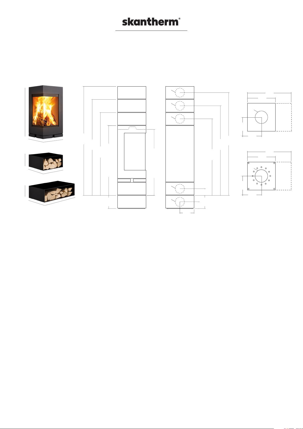
MODEL ELEMENTS | MODEL ELEMENTS (RLU)
Chimney stove for solid fuels (split logs)
Shared chimney flues admissible. This stove is not a low burning stove!
European Standard EN 13240 I Test Report N°: RRF - 40 13 3220 I certification from DIBt: Z-43.12-348 | Test Centre ID: 1625
80,6 cm
19,7 cm
19,7 cm
ø 175
ø 175
ø 175
40,0 cm
40,0 cm
40,0 cm
40,0 cm
40,0 cm
60,3 cm
Data in cm
** Flush mounting depth with stationary firing chamber / *** Flush mounting depth with rotatable firing chamber
162,6
142,3
122,0
101,7 [Minimum height]
20,3
Height of different
combinations of »elements«
101,1 ** / 102,6 ***
ø 175
ø 175
Standard dimensions height smoke
discharge and external fresh air supply
20,0
10,7
10,7
20,3
112,2
132,5
152,8
60,3
40,0
ø 180
20,0
20,0
Smoke discharge (top)
60,3
40,0
ø 180
20,0
20,0
Fresh air supply (bottom)
technical data
The following values were determined under test conditions:
CO emission in %:
Average feed pressure in Pa:
Nominal thermal output in kW:
Room heat output in kW:
Energy efficiency in %:
Dust mg/Nm³ (13 % O2):
Operation with closed fire box (construction type 1):
Waste gas mass flow rate in g/s:
Average OGC content in mg/Nm³:
Average CO content in mg/Nm³:
Waste gas connection piece temperature in °C:
Waste gas temperature (ta-tr) in °C:
Weight and dimensions:
Weight of the fire place in kg (steel, firing chamber/small/ big box):
Stove dimensions in mm (height / width / depth):
Fire box dimensions in mm (height / width / depth):
Fire box opening dimensions in cm²:
Pipe diameter (waste smoke) in mm:
Connectivity flue tube top and bottom or laterally (t /b* /l*):
Fresh air connection piece diameter in mm:
Connectivity combustion air rear, side and bottom (r /s/ b):
..............................................................................................................................................0,06
................................................................................................................................12
...........................................................................................................................5,0
.............................................................................................................................2,5 - 5,5
........................................................................................................................................80,0
.....................................................................................................................................< 40
..........................................................................................Yes
......................................................................................................................4,60
........................................................................................................................37
........................................................................................................................750
.................................................................................................300
..................................................................................................................270
...........................................................................806 / 400 / 400
.......................................................................520 / 310 / 310
...............................................................................................................1712
................................................................................................................150
...................................................................t / b* / l*
.....................................................................................................100
......................................................................r / s / b
.................................................130 / 18 / 24
*Smoke discharge, bottom or laterally from a box above the firing chamber possible (technical and/or base box)
Page 2
Safety distances
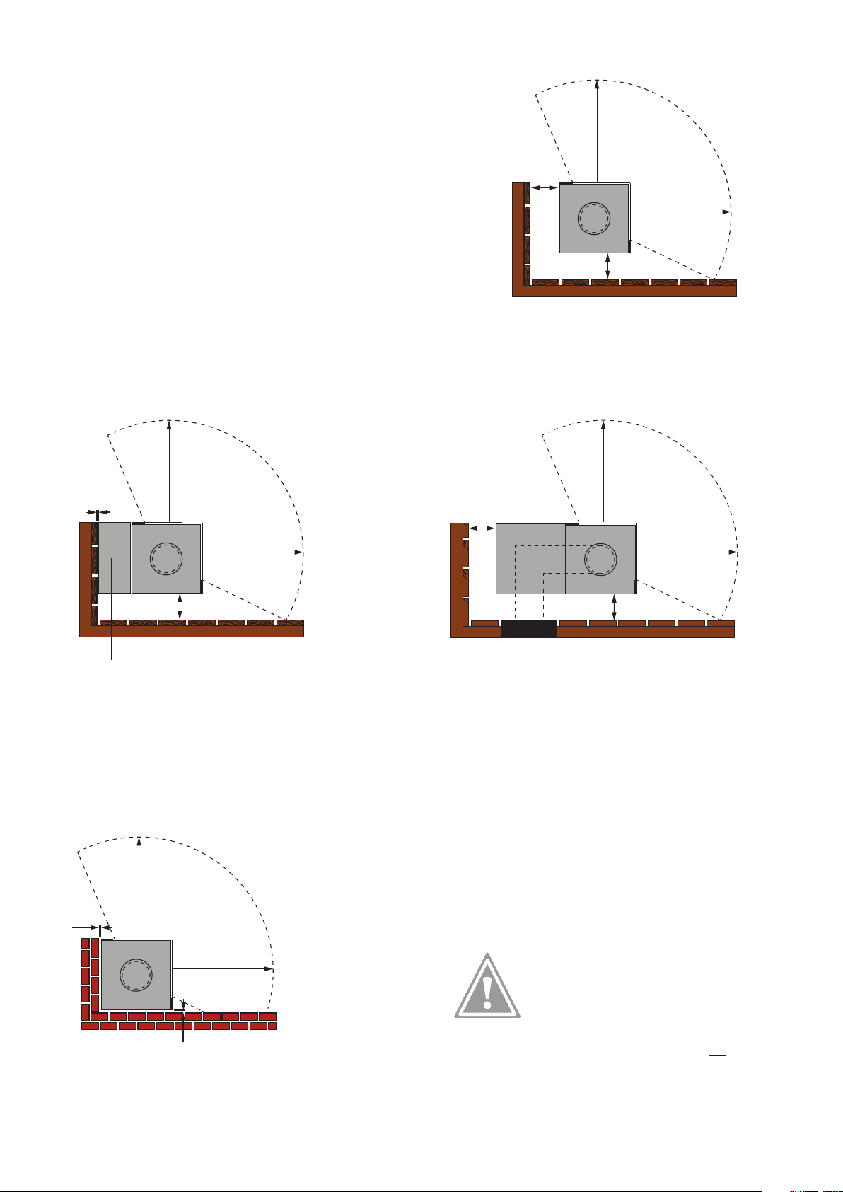
Safety distances to INFLAMMABLE walls / materials
For »elements« without lateral extension element, the following safety
distance to combustible elements and walls should be observed.
Lateral:
......................................................................min. 15 cm
15 cm
80 cm
radiation area of the
front glass
Front (within the radiation area of the front glass):..min. 80 cm
combustion
chamber
15 cm
(Top view)
Further safety distances to INFLAMMABLE walls / materials when extension elements are used
80 cm
radiation area of the
front glass
< 1 cm
80 cm
radiation area of the
front glass
15 cm
80 cm
80 cm
combustion
chamber
15 cm
(Top view)
Extension element without smoke discharge tube Extension element with smoke discharge tube ducts
The external side of extension elements, where smoke
discharge tubes cannot be guided through, can be
installed at only some millimetres to inflammable
elements or walls, since it is heated only slightly during
operation.
Safety distances to NON COMBUSTIBLE walls / materials
80 cm
2 cm
radiation area of the
front glass
80 cm
combustion
chamber
15 cm
(Top view)
Extension elements, through which smoke discharge tubes
are fed can be installed at a distance of at least 15 cm to
combustible elements or walls (please observe the DIN of
the smoke discharge tubes).
80 cm
combustion
chamber
(Top view)
2 cm
For »elements« with or without lateral extension elements,
the above mentioned safety distance to non combustible
elements and walls (such as concrete, stone, plaster)
should be observed.
Please observe that the stated distances to combustible
materials are fire protection information that does not
take possible material changes caused by heat such as
discoloration or stress fractures into consideration.
Page 3
Important installation instructions
_Installation:
It is imperative that the chimney stove be installed in strict conformity with any prevailing national and European standards as well as
any applicable local regulations. Please contact your local chimney sweep prior to installing your chimney stove.
_This skantherm fireplace model is suitable for integration into an alcove/cladding provided the safety distances indicated are observed.
_Installation of chimney stove:
Make sure that the floor‘s carrying capacity is sufficiently high. In case of inadequate carrying capacity, suitable adjusting measures
(e.g. plate for load distribution) are to be taken.
_Cleaning:
Make sure to clean your chimney stove at regular intervals. This also applies to emptying the ash box and cleaning the shaking grate.
Also make sure to clean the connection pieces and flues at least once a year and to apply a heat resistant copper paste on all moving
parts such as hinges at least once a year, too. Use a damp cloth and clear water to clean window glasses. Contact your local chimney
sweeper for professional cleaning of your chimney at regular intervals.
_Ventilation of room and chimney stove:
Please ensure sufficient ventilation of the room. Never close air supply openings or convection shafts of the stove.
_The fire chamber door of a stove operating independently of ambient air always has to be kept closed as otherwise, the
operation independent of ambient air cannot be guaranteed!
_Combustion air: In order to ensure a proper operation, sufficient air flow for the combustion has to be guaranteed. This
chimney stove is constructed to operate independently of ambient air and can either be connected directly outwards with a
combustion air conduit (type: FC41x) or to the air channel of an air exhaust chimney– LAS- (type: FC51x). The pressure loss
of the combustion air conduit may not be higher than 3 Pa. When using a flexible aluminium tube, please ensure that the pipe
is protected against mechanical damages. The combustion air should be lockable outwards with an air damper and the position
of the air damper should be visible in the installation room. Combustion air conduit as well as the connection piece need to be
airtight.
_The fireplace is not allowed for waste incineration!
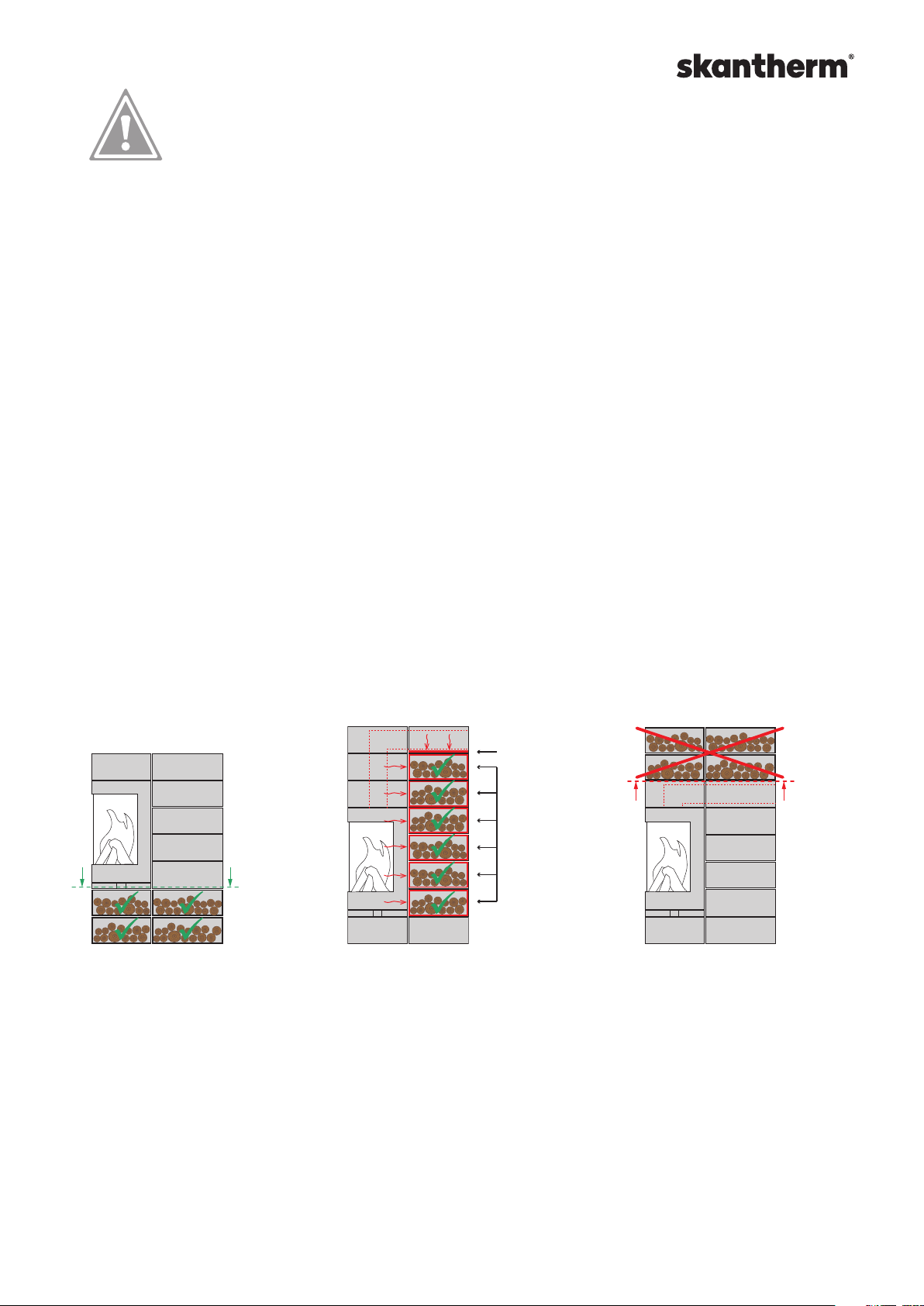
_Note concerning the STORAGE OF INFLAMMABLE MATERIALS (e.g. firewood) in attached ELEMENTS:
The following prerequisites must be fulfilled if you want to store highly flammable materials such as firewood which are sufficiently
ventilated to the front/to the side:
Necessary radiation
protection plate
Necessary radiation
protection insert
1.
The element is located below or below/
laterally from the firing chamber. Here,
no significant heat transmission takes
place. It is also possible to close this
element by means of a flap.
2.
The element is mounted laterally at the
firing chamber and is equipped with a special radiation protection insert against heat
transmission. If further extension elements
with smoke discharge tubes are provided
3.
The storage of flammable materials
above extension elements where
smoke discharge tubes are fed
through is not possible.
above this element (for the storage of fuel),
these must be equipped additionally with a
radiation protection plate on the ground.
_Elements above the firing chamber may only be used for storage stones.
The storage of objects and in particular of flammable materials is not possible.
For more detailed information please refer to the general assembly and operation instructions.
Page 4
Instructions regarding the installation of radiation protection inserts and plates
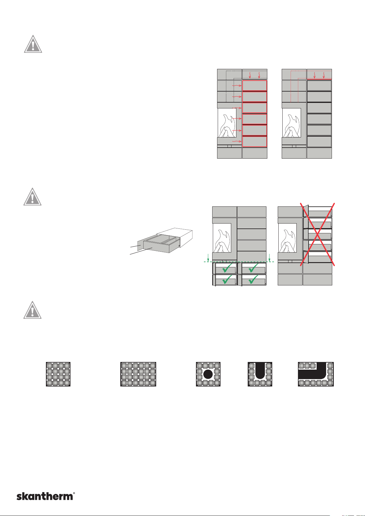
For fire protection requirements, each element that can be used as a
heating box or storage space (e.g. for the storage of flammable materials
such as firewood) and which are directly located at the side of the firing
chamber or adjacent to an element with a flue tube require the use of an
additional radiation protection insert that is inserted into the element.
No radiation protection insert is required below the firing chamber.
Radiation protection insert, 38,0 x 39,0 x 17,7 cm, art. # 8070121
Radiation protection insert, 58,3 x 39,0 x 17,7 cm, art. # 8070122
Should an element with a flue tube be provided above the heating
box or a storage place with a flue tube, a radiation protection plate
must additionally be inserted into the below element against heat
transmission.
Radiation protection plate, 39,0 x 39,0 x 2,0 cm, art. # 8070224
Radiation protection plate, 59,0 x 39,0 x 2,0 cm, art. # 8070225
Instructions regarding the lockable door
Due to a possible heat accumulation, the basic boxes with lockable doors
must be installed below or below/laterally from the firing chamber!
Optical boxes with
radiation protection insert
Technical box with radiation
protection plate inserted
Correct installation: Incorrect installation:
Lockable door
Wooden drawer
Lockable door, 38,8 x 18,5 cm, art. # 8070123
Lockable door, 58,8 x 18,5 cm, art. # 8070124
Wooden drawer, 36,0 x 38,5 x 10,0 cm, art. # 8070222
Wooden drawer, 56,0 x 38,5 x 10,0 cm, art. # 8070223
Instructions regarding skantherm thermostones
The thermostones can be integrated into an element box of a width of 40,0 cm and 60,3 cm. The weight of a thermostone is
approx. 5 kg. Please observe that the total weight of all thermostones in elements lying one above the other must not exceed 160 kg.
Declaration of weight regarding the element
boxes with integrated themostones:
(Top view) (Top view)
elements box,
40,0 cm wide,
16 thermostones
(approx. 80 kg)
elements box,
60,3 cm wide,
24 thermostones
(approx. 120 kg)
Examples of weight declarations for element boxes with
integrated thermostones and flue tube:
12 thermostones,
approx. 60 kg
10 thermostones,
approx. 50 kg
12 thermostones,
approx. 60 kg
skantherm Wagner GmbH & Co. KG
Von-Büren-Allee 16 | D-59302 Oelde | T 00 49 (0) 25 22-59 01 0 | F 00 49 (0) 25 22-59 01 149 | [email protected] | www.skantherm.de
Page 5
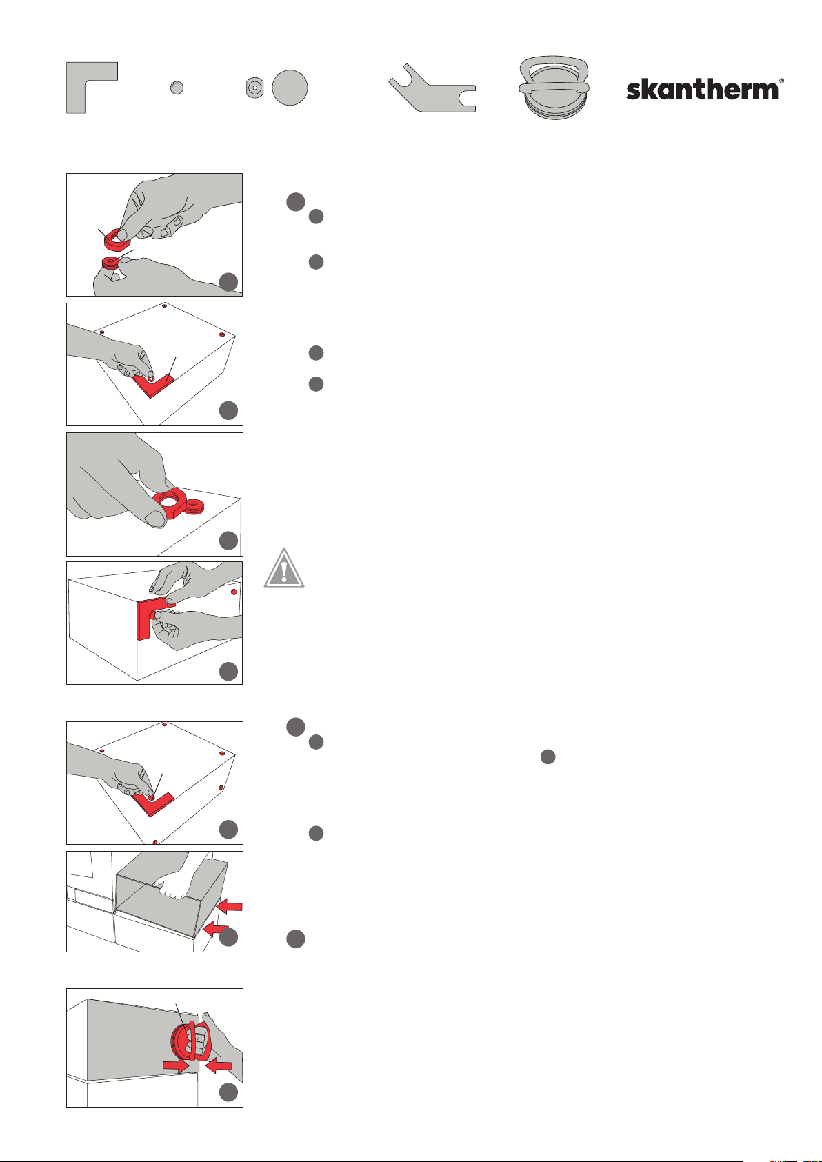
Accessories:
1 pc. wooden positioning
bracket (MDF)
nut
threaded piece
6 pcs. magnet
per optical box
positioning
angle
Optionally: 4 pcs. adjustment
feet, including rubber disk,
art. #: 80702111
1
1.1
1.2
1 pc. adjustment feet key 1 pc. vacuum lifting tool
Installation of the extension elements
Installation of the 1st extension elements
1.1
Mounting of the adjustment feet by gluing. An adjustment foot consists of an internal
threaded piece and the pertaining nut. The threaded piece is additionally provided with an
adhesive layer on one side. Remove the nut from the threaded piece and put it aside.
1.2
Place the positioning bracket onto the extension element and align it in accordance
with the external edges of the extension element. Remove the paper protection from the
adhesive layer. Now, you can position the threaded piece with the adhesive layer carefully
into the rounded inner side of the bracket. Press the threaded piece firmly in order to
make sure it will stick to the bracket. For the three other adjustment feet of the extension
elements, proceed the same way as described above.
1.3
Now, screw the nuts on the mounted threaded plates and turn the extension feet
upright on its adjustment feet.
Now, using the positioning bracket - position two magnets on the lateral surfaces of
1.4
the external element that you intend to add to the already existing stove combination. For
this purpose, align the positioning bracket at the external edges and position the magnet
into the rounded inner side of the bracket. Erect the extension element at a distance of
approx. 1.5 to 2 cm to the final position. Push one of the rubber disks under each adjusting
leg in order to prevent the extension element from slipping.
Now, push the extension element carefully towards the fireplace. The magnets now cling
audibly to the combustion chamber. Using the adjustment feet key, you can now align the
extension element with regard to its height.
magnet
vacuum lifting tool
1.3
1.4
2.1
2.2
Warning:
The magnet position determined by the positioning bracket must be observed by all
means. Non-observance could lead to an unintended heat transmission to the extension
elements.
Pace maker
Magnets may have an impact on the function of pace makers and implanted defibrillators.
As a person concerned you should keep a sufficient distance to such magnets. Please
warn other people wearing such devices before they approach the magnets.
2
Installation of one further extension element
2.1
Position the positioning bracket onto the extension element again and carefully
position four magnets as described under step .
Now, determine the lateral surface that is to be placed adjacent to the firing chamber or
another extension element. Place the magnets in two corners each using the positioning
bracket. Make sure the surface is nonmagnetic. Rotate the extension element onto the
four magnets.
2.2
Now, lift the extension element into that position where it is to be mounted. Align one
of the outer edges of the extension element in such a way that it is flush with the outer
edge of the extension element below and tilt the extension element slowly onto the
magnets. It is very important to work with precision since the subsequent alignment is
possible only to a small extent.
3
Removal of the lid
A lid can be removed using the vacuum lifting tool supplied.
Place the vacuum lifting tool carefully near the external edge of the lid tool.
Press both brackets together. The lid can now be pulled out of the box. Please loosen the
vacuum lifting tool from the lid immediately in order to avoid damage to the paintwork.
The use of a vacuum lifting tool is not needed for the insertion of a lid. The sheet is simply
pushed into the open side of the extension element.
1.4
3
skantherm Wagner GmbH & Co. KG | Von-Büren-Allee 16 | D-59302 Oelde | T 00 49 (0) 25 22-59 01 0 | F 00 49 (0) 25 22-59 01 149 | [email protected] | www.skantherm.de
 Loading...