

Page 1

Manual
Weighing Machine
AMV1
A/S SKALS MASKINFABRIK
HOVEDGADEN 56
DK-8832 SKALS, DENMARK
Tel.: +45 87 25 62 00
Fax: +45 86 69 49 99
Email: skals@skals.dk
http://www.skals.dk/
1
Page 2

1 Contents
1 Contents ........................................................................................................................ 2
2 Introduction ................................................................................................................... 3
3 Safety ............................................................................................................................ 4
3.1 Pictograms .......................................................................................................................... 4
4 In general ...................................................................................................................... 5
4.1 Feed belt ............................................................................................................................. 6
4.2 Vibration chutes .................................................................................................................. 6
4.3 Weighing tank ..................................................................................................................... 7
4.4 Cross conveyor ................................................................................................................... 8
4.5 Sack platform ...................................................................................................................... 9
4.6 Operating panel .................................................................................................................. 9
5 Operation ...................................................................................................................... 9
5.1 Set-up ................................................................................................................................. 9
5.2 Electrical connection ........................................................................................................... 9
5.3 Start-up ............................................................................................................................. 10
6 Control ......................................................................................................................... 11
6.1 Homescreen ..................................................................................................................... 11
6.2 Settings ............................................................................................................................. 11
6.3 Skals ................................................................................................................................. 12
6.4 Automatic operation settings ............................................................................................ 13
6.5 Manual operation settings ................................................................................................ 17
6.6 Emptying the machine ...................................................................................................... 18
7 Service and maintenance ............................................................................................ 18
7.1 Bearings ........................................................................................................................... 18
7.2 Gear .................................................................................................................................. 18
7.3 Belt ................................................................................................................................... 18
7.4 Vibration chutes ................................................................................................................ 20
7.5 Cleaning ........................................................................................................................... 21
8 Transport ..................................................................................................................... 22
9 Troubleshooting .......................................................................................................... 23
9.1 Fault described in display. ................................................................................................ 23
2
Page 3

9.2 Other faults. ...................................................................................................................... 24
10 Spare parts list ......................................................................................................... 25
10.1 Weighing tank ................................................................................................................... 26
10.2 Vibrator chute ................................................................................................................... 27
10.3 Feed belt ........................................................................................................................... 28
10.4 Cross conveyor ................................................................................................................. 29
11 Diagrams .................................................................................................................. 31
12 EU Declaration of Conformity ................................................................................... 32
2 Introduction
Read this user manual thoroughly before using the machine.
The machine is use for weighing potatoes, onions, carrots and other similar products.
The machine can weight portion sizes from 1–50 kg.
The machine can weigh large portions up to 1000 kg.
The machine may be operated in a temperature range of -10 to +40 C°.
The information plate and CE label are positioned on the side of the machine, close to the
control panel.
3
Page 4
3 Safety
Any persons working in the close vicinity of the machine must not wear loose-fitting
clothing as this will be hazardous.
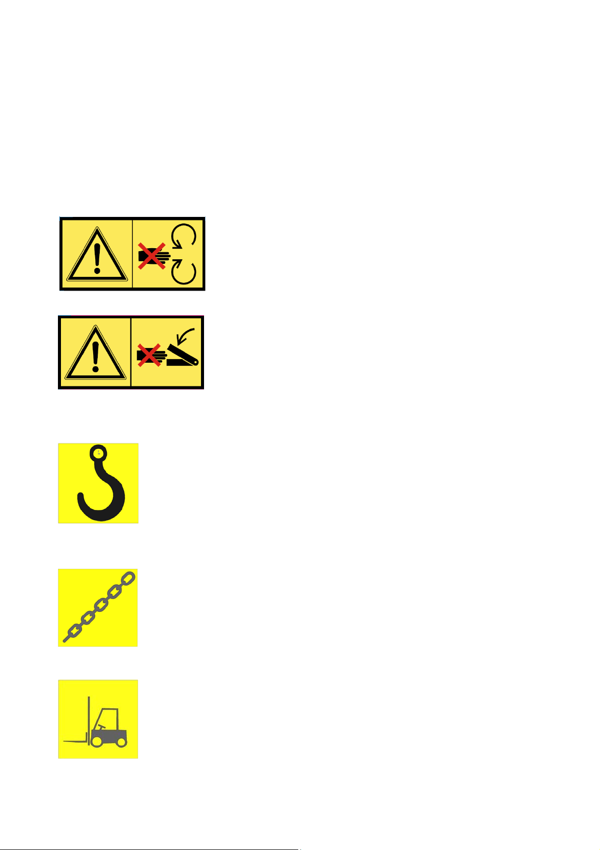
3.1 Pictograms
Two types of pictograms are positioned on the machine. Warnings and instructions.
Warnings
HAZARD - ROTATING PARTS.
Avoid touching or coming into contact with the machine's
moving parts. This applies to fingers and clothing, since this
can lead to mutilation.
CRUSH HAZARD.
Avoid touching or coming into contact with the machine's
moving parts. This applies to fingers and clothing, since this
can lead to mutilation.
Instructions
HOOK
Describes where the hook must be positioned when the machine is to be
lifted by a crane.
STRAP HERE
Describes where the machine shall be secured during transport.
FORKLIFT TRUCK
Describes where the forks must be positioned when lifting with a forklift
truck.
4
Page 5
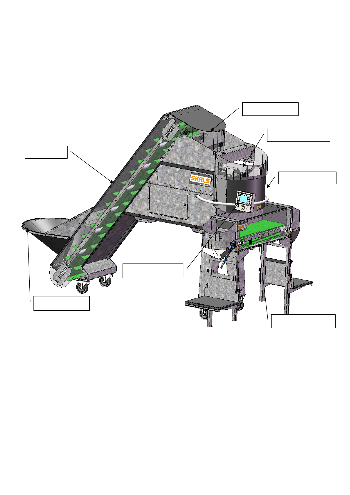
4 In general
Description of machine
Feed belt
Buffer tank
Vibration chutes
Weighing tank
Feed hopper
Operating panel
Cross conveyor
5
Page 6
4.1 Feed belt
The feed belt transports the products from the feed hopper up to the buffer tank above the
vibration chutes. The buffer tank has two sensors that activate and deactivate the feed
belt.
To achieve optimal operation, it is important that the feed hopper is always filled
with products.
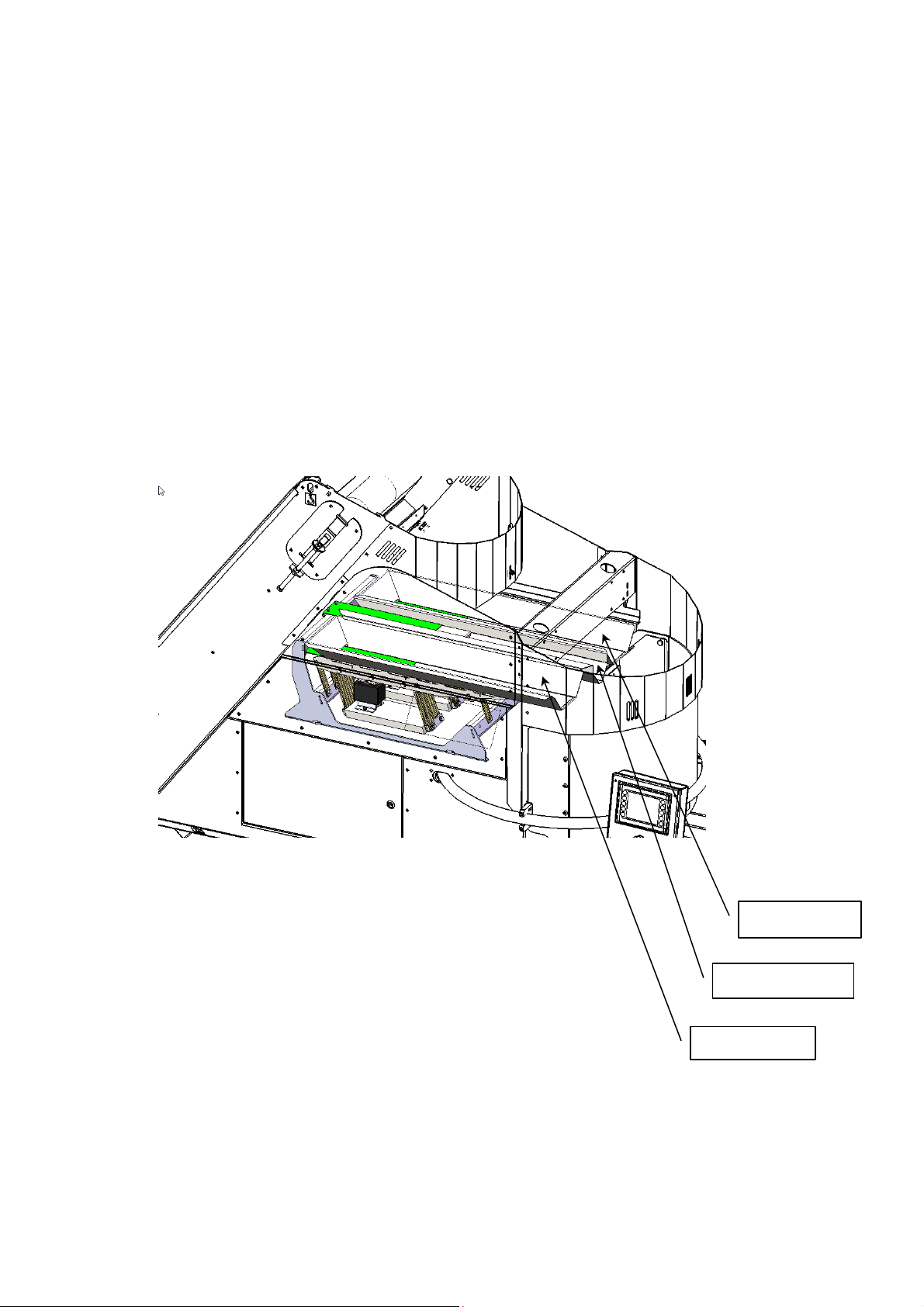
4.2 Vibration chutes
The machine is equipped with three vibration chutes, designed to fill and dose the
weighing tank.
All three of the vibration chutes switch on automatically when the weighing tank shall be
filled and only two of the chutes operate when dosing for the required weight.
Fill chute.
Dosing chute
Fill chute.
6
Page 7
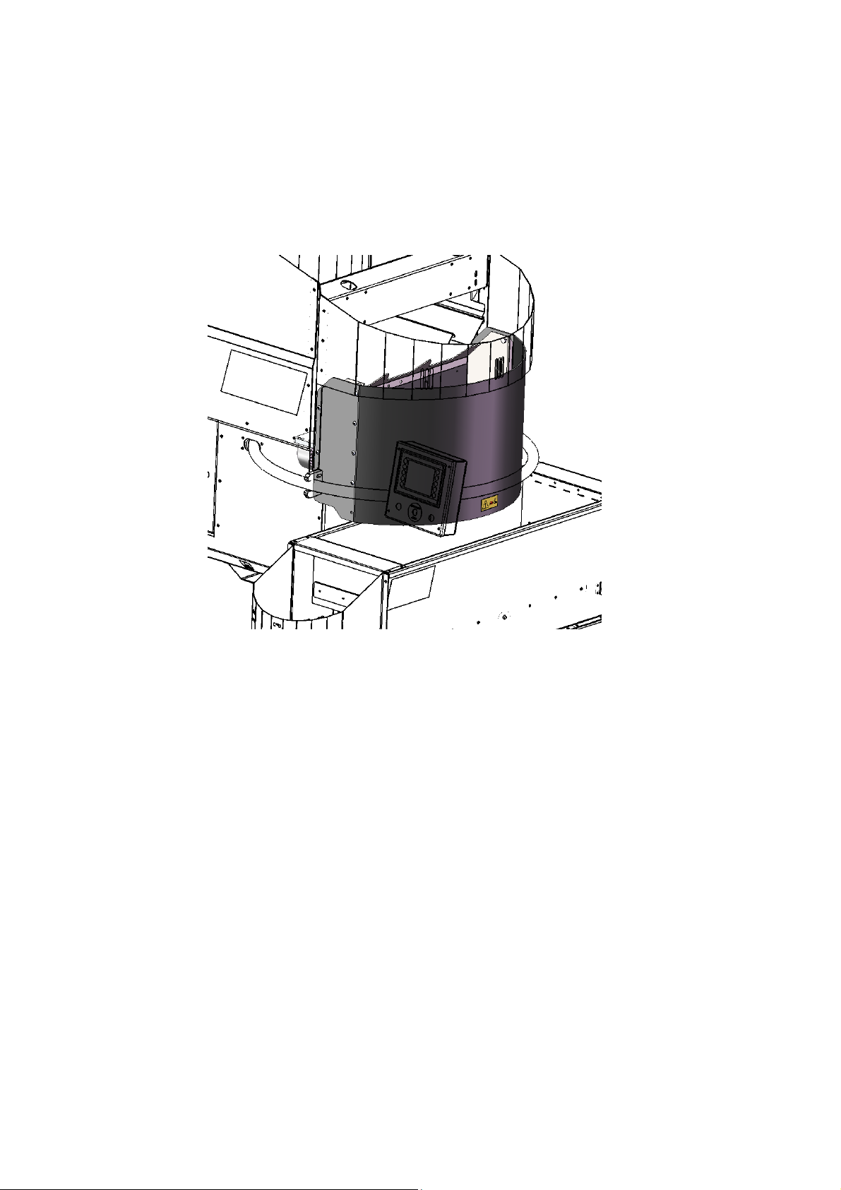
4.3 Weighing tank
The weighing tanks' volume capacity is 57 l.
The weighing tank must be checked regularly and if required, cleaned of any soil that has
accumulated.
During operation, the weighing tank must not be touched otherwise the weighing result will
not be correct.
7
Page 8
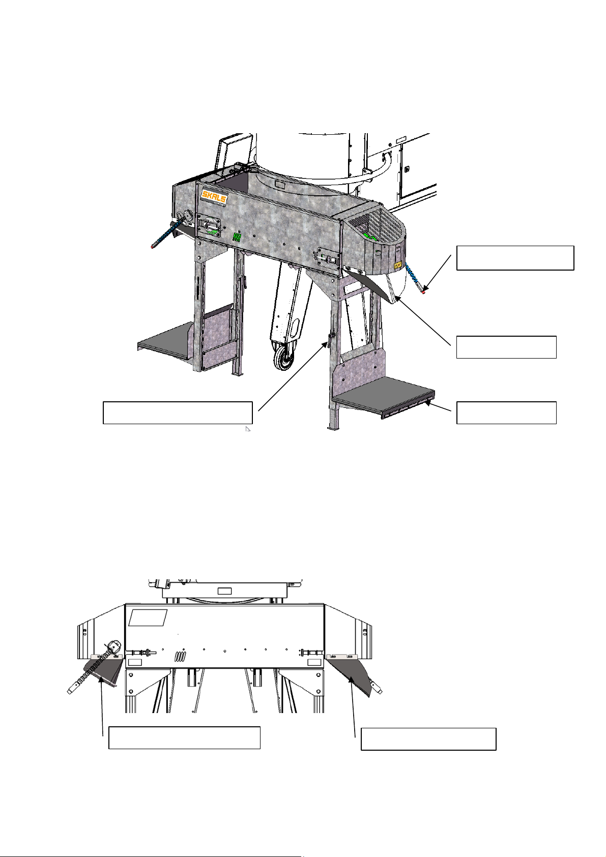
4.4 Cross conveyor
The cross conveyor allows the machine to be operated by two people at the same time.
Operation sensor
Outlet hopper
Handle for stabiliser leg
Sack platform
When the operating sensor is activated on a specific side, the cross conveyor will transport
the next portion to that side.
NB: The machine 'remembers' an activation of the operating sensor, even though the
cross conveyor is not ready to deliver a portion!
The machine is supplied with four outlet hoppers as standard. Two hoppers for portion
sizes 1–9 kg and two hoppers for 10–50 kg.
Outlet hopper 10–50 kg
Outlet hopper 1–9 kg
8
Page 9

4.5 Sack platform
When the height of the sack platform shall be changed, loosen the two finger screws on
the platform and raised/lower the platform and then re-tighten the finger screws.
When weighing portions that weigh more than 10 kg, lower the stabiliser leg at the sack
platform until it supports on the level surface.
Handle for
stabiliser leg
Stabiliser leg
4.6 Operating panel
The operating panel consists of a touch display and a stop.
All of the machine's electrical functions are operated via the touch display.
5 Operation
Before commissioning the machine, check it to ensure it has not been damaged during
transport.
Any defects must be reported to the dealer immediately.
5.1 Set-up
To ensure correct weighing, the machine must be placed on a stable and level surface.
5.2 Electrical connection
The electrical connection must comply with national applicable regulations.
1 Phase 230 V - N + PE
9
Page 10

5.3 Start-up
1. Enter the desired portion size and total number of portions that are to be weighed
using the operating panel.
2. Next, select the programme that is to be used (potatoes, carrots, onions or
optional).
3. Press the "Start" button on the display.
4. The operating sensor is activated.
NB: In the case of start-up after the portion size has been changed the machine may
initially weigh inaccurately. The machine will regulate this automatically after a few
weighings.
10
Page 11
6 Control
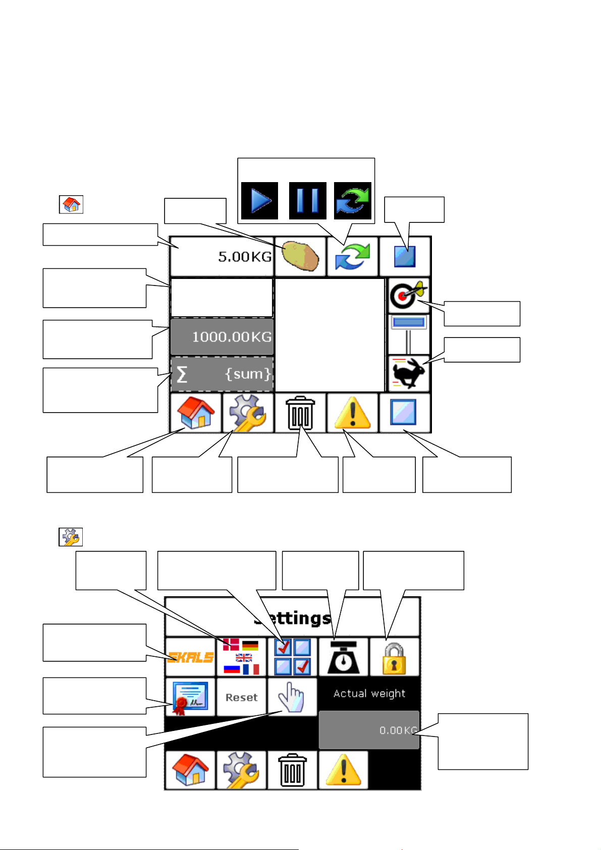
6.1 Homescreen
Portion sizes
Total number of
portions
Actual weight in
the weighing tank
∑ Sum of weighings
X Average value
Ϭ Standard deviation
Return to
homescreen
Start/Pause/Repeat
Product
6/10
Settings Empty function Alarms
6 5.01 kg
5 5.10 kg
4 5.04 kg
3 5.00 kg
2 5.03 kg
1 5.07 kg
Stop
Precision
Speed
Reset alarms
6.2 Settings
Language
setting
Skals contact
information
Verification
Manual
operation
settings
Automatic
operation settings
Calibration
of scales
Scales settings
locked
Actual weight
in the
weighing tank
11
Page 12

6.3 Skals
Skals contact information is shown here
Should you have any questions about the machine, contact your dealer in the first
instance.
Verification
The verification ID and date of last filling is show here.
12
Page 13
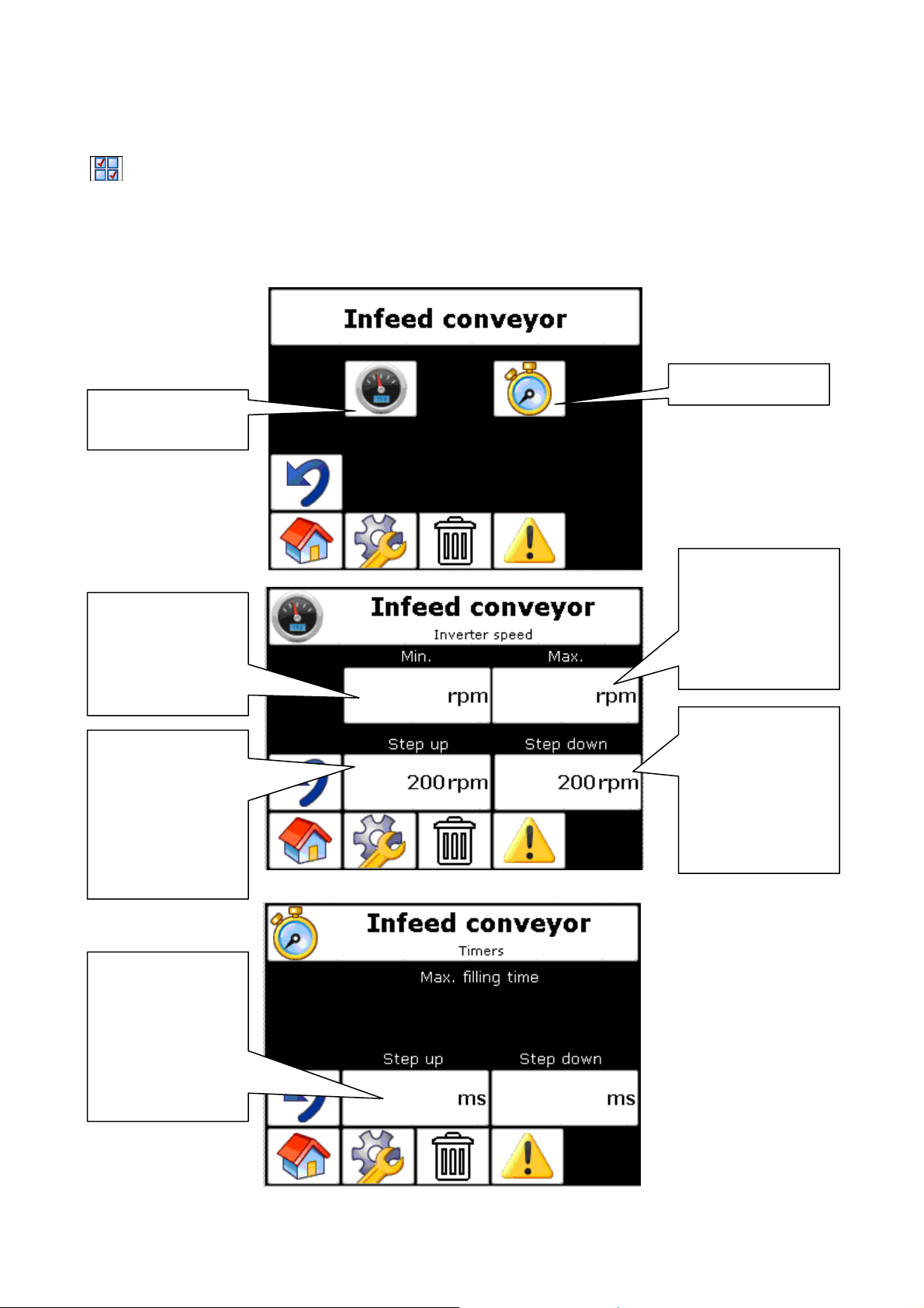
6.4 Automatic operation settings
There are four areas that can be set: Feed belt, vibration chutes, weight and cross
conveyor, of which the last three are relevant for normal operation.
Feed belt
Speed, see next
image
Time setting
Minimum rpm of
the drum motor
for the feed belt
should be set to
700 rpm.
Total rpm, the
drum motor
speed increases
every time it
accelerates.
Should not be
changed.
700 1500
Maximum rpm
of the drum
motor for the
feed belt should
be set to
1500 rpm.
Total rpm, the
drum motor
speed lowers
every time it deaccelerates.
Should not be
changed.
Time interval
between
automatic
change of
speed.
1000 2000
13
Page 14
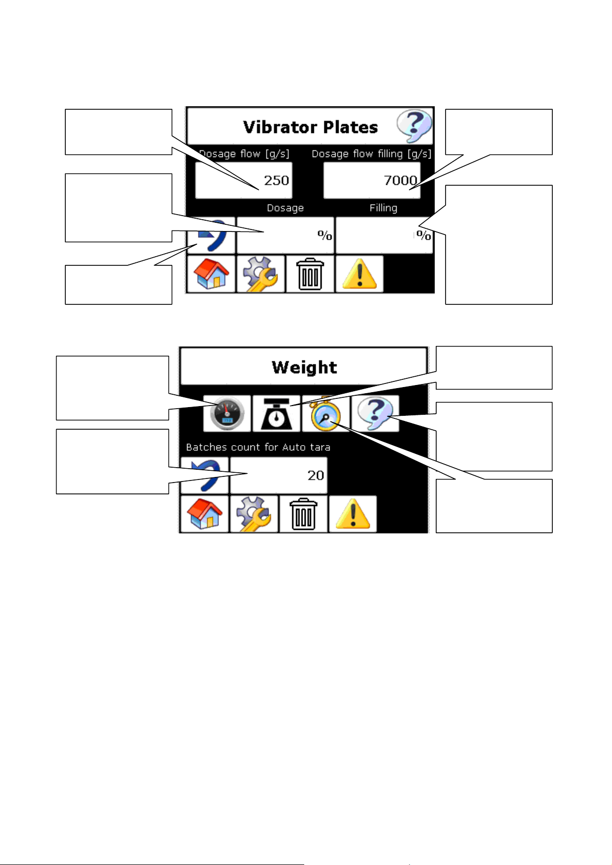
chute
Vibration chutes
Estimated flow
when dosing
Vibration power
in percent.
Should not be
less than 50%
Back to
previous menu
Scales
Motor speed for
tank shutter
Should not be
changed.
Total number of
portions between
each auto taring.
See explanation
Auto taring
Automatically tares the scales zero point after a set number of portions (e.g. 20).
In the case of dirty products, it is relevant to have a low total number of weighings between
each auto taring. Build up of dirt in the weighing tank affects the weighing result.
75
85
Estimated flow
when filling
Vibration power
in percent.
Should not be
less than 55%
and should
always be
greater than
2
Scales settings
See next image
Product specific
settings.
(potatoes, carrots
etc.)
Alarm times
Should not be
changed.
14
Page 15

Weight Speed
Weight settings
Back to
previous menu
Offset 25 kg:
When a double portion is made (over 25 kg), Offset 25 kg must be between 1500 and
3500 g to stop around the 25 kg. This is necessary to compensate for the run-on time and
prevent the weighing tank from becoming over filled with the first portion.
Tolerance
This is the limit for when the scales begins to be regulated.
If the products that are being weighed weigh up to 100 g, the tolerance must be the same
or 10 % greater.
Controller parameter
Parameter that determines how aggressive the controller reacts
Weigher opening
speed
Tolerance interval
in grams, see
explanation
Controller
parameter
15
Page 16
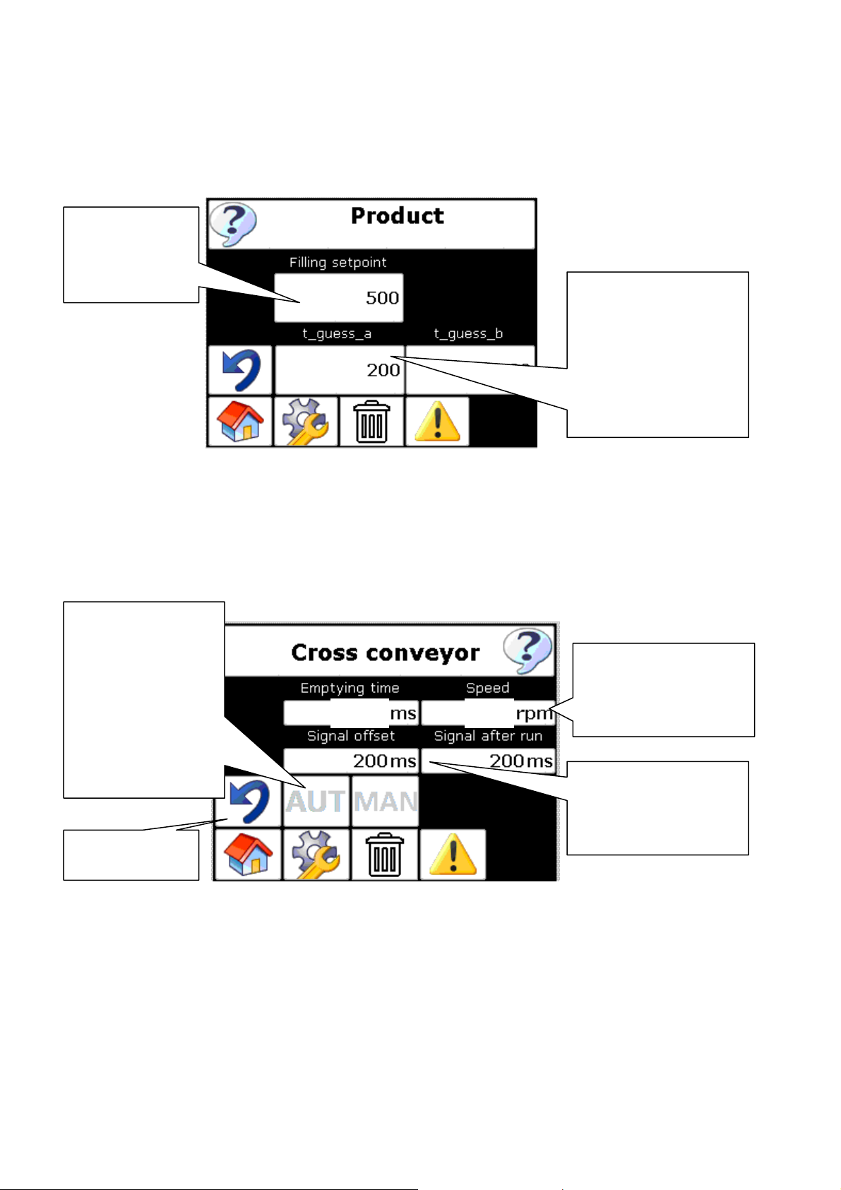
Product specific parameters
Filling setpoint
is controlled by
the slider on
the main page
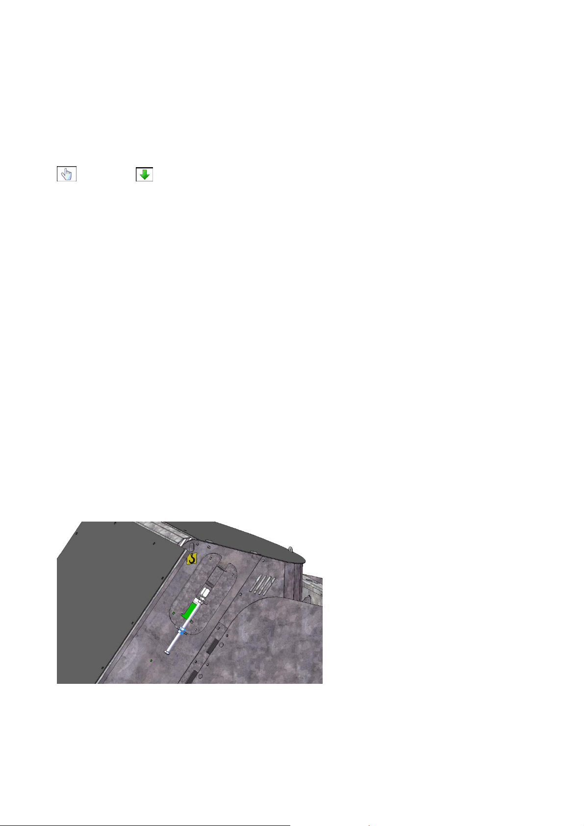
Cross conveyor
Aut. or manual
outfeed mode.
Manual = sensor
Aut. = after first
touch of the
sensor, next
portions are
feeded
automatically
Back to
previous menu
Empty time
The time that is set to ensure that the belt is completely empty.
Speed
If there are problems with the products coming out of the outlet hopper, reduce the speed.
2300 700
Time guess_a is a
value used for
portions up to 10kg.
Lighter products =
higher value.
The speed of the
cross conveyor
should be between
600 and 900 rpm
Delay and run-signal
to next machine
External signal
16
Page 17

6.5 Manual operation settings
During manual operation, all of the functions can be set and the machine operated.
NB: In manual operation mode, all of the alarms and sensors are de-activated.
Language
Five languages are available.
English
German
Danish
French
Russian
Lock
When the scales are locked, there is limited access to certain functions.
Scales guide
Programme 0-3
Scales guide (calibration)
To calibrate the scales, follow the instructions in the display.
Place a known weight in the weighing tank during calibration.
The weighing tank must be clean inside.
Every time the scales are calibrated a new ID number is generated, which can be seen
under the verification ID and a date for the last calibration.
Alarms
All of the alarms that can be triggered are shown in the troubleshooting section.
When an error is observed and corrected, the alarm is reset
17
Page 18
6.6 Emptying the machine
If the machine is to be completely emptied, continue to weigh portions without filling the
intake hopper with any products. Once the vibration chutes have operated for a longer
period than normal, press Stop.
Next, empty the weighing tank and the cross conveyor by accessing the manual settings
and press to empty.
7 Service and maintenance
During service and maintenance, ensure power has been disconnected at the main switch
and the main switch is locked.
7.1 Bearings
All of the bearings and motors and the loose drum have been lubricated at the factory and
require no maintenance.
7.2 Gear
The worm gear that drives the weighing tank's open/close function has been lifetime
lubricated with synthetic grease for operation in standard temperature range (-10 to +40
°C).
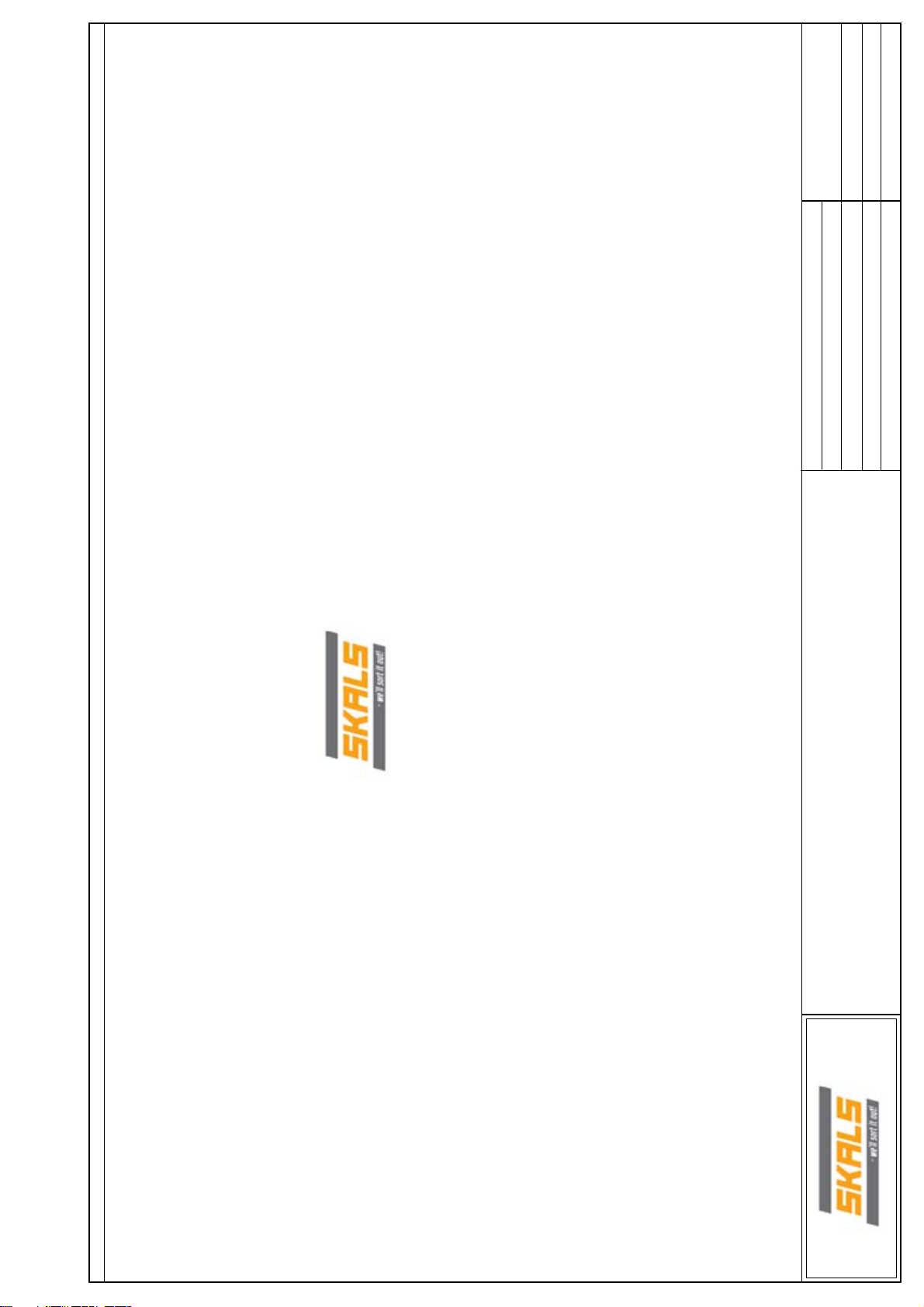
7.3 Belt
The machine has two PVC belts fitted. A feed belt and a cross conveyor.
Both belts must be checked regularly and adjusted if required to ensure a long lifetime.
Tighten the belts by loosening the two nuts marked with blue (on both sides) and then
tighten the belt by tightening the top nut. Once the belt has been adjusted, re-tighten the
18
Page 19

bottom nut. The same procedure is used to adjust the belt to operate in the centre.
However, the tightening must only be done in the side the belt moves to.
At all times it is the responsibility of the owner to ensure the belts have been adjusted
correctly.
If the belts have not been adjusted correctly, the warranty for the belts is void.
19
Page 20

7.4 Vibration chutes
All bolts and vibration chutes should be re-tightened every 200 hours of operation.
To access the bolts, remove the screen marked in blue.
The bolts are marked in blue, and should be tighten to 18 Nm.
20
Page 21

7.5 Cleaning
In the case of high-pressure cleaning, direct spraying must be avoided in the following
areas: loose drum, gear motors, control cabinet, electronic control box, load cell,
connectors and motors on vibrators.
If products with loose skin are being weighed, the vibrator chutes should be cleaned on a
daily basis.
Good cleaning and maintenance are important to achieve a high degree of reliable
operation and low maintenance costs.
21
Page 22

8 Transport
If the machine shall be lifted by crane, this must be done using the integrated lifting points
in the top of the machine. If the machine shall be moved by forklift truck, this must be done
using the integrated fork pockets.
NB: Always stay well clear of suspended loads.
During transport the machine must be secured to the surface, as shown with the orange
lines.
22
Page 23

9 Troubleshooting
NB: The machine must ALWAYS be switched off at the main switch when work on
mechanical parts shall be carried out.
9.1 Fault described in display.
Alarm text Cause Solution
Shutter in weighing tank
taking too long to close.
Scales taking too long to fill
up.
Sensor is not adjusted
correctly.
Defective sensor. Check the conductor to the
Foreign bodies are blocking
the shutter in the weighing
tank.
There are not enough
products in the buffer tank.
Feed belt not regulating to
faster speed.
Products are blocked in the
buffer tank.
Adjust the sensor closer to
the crank plate
(distance 1-3 mm).
sensor. Replace sensor.
Remove foreign bodies.
Fill the intake hopper with
products.
See other faults.
Remove the blockage in the
buffer tank.
Set the plate in the buffer
tank to the applicable
product's size.
Fault on all of the frequency
converters.
Aborting of both belts and
scales.
Automatic fuse switched off. Switch on automatic fuse
(see control).
23
Page 24

9.2 Other faults.
Error Cause Solution
Weighing tank or cross
conveyor does not start with
operation of operation
Operation sensor is
defective.
Check the conductor to the
sensor. Replace sensor.
sensor.
Buffer tank is not full and the
feed belt is not operating.
The top sensor in the buffer
tank is dirty or defective.
Clean sensor and reflector.
Feed belt not regulating to
faster speed.
The bottom sensor in the
buffer tank is dirty or
defective.
Green LED on sensor must
be lit at all times (indicates
Clean sensor and reflector.
Check the conductor to the
sensor.
Replace sensor.
sensor is in contact with the
control system).
24
Page 25

10 Spare parts list
When ordering spare parts, please state machine type, serial number and any product
number.
25
Page 26

10.1 Weighing tank
26
Page 27

10.2 Vibrator chute
27
Page 28

10.3 Feed belt
28
Page 29

10.4 Cross conveyor
29
Page 30

Complete capacitive sensor
30
Page 31

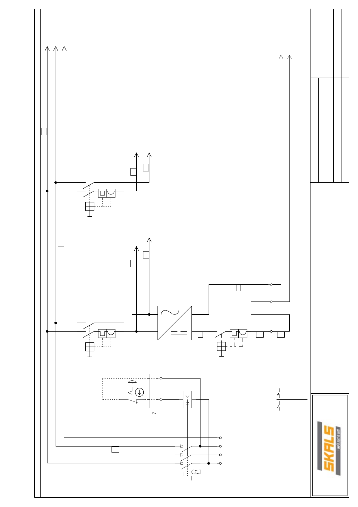
11 Diagrams
31
Page 32

12 EU Declaration of Conformity
Manufacturer
Company name: A/S Skals Maskinfabrik
Address: Hovedgaden 56
DK-8832 Skals, Denmark
Telephone: +45 87 25 62 00
hereby declares that
Machine: Weighing machine
Brand:
Type, serial no., year:
Has been manufactured in conformity with the:
1 Machinery Directive 2006/42/EC
2 Low Voltage Directive (LVD) 2006/95/EC
3 Electromagnetic Compatibility (EMC) Directive 89/336/EEC and the
amended 93/68/EEC.
Title:
Name: Søren Lund Madsen
Company: A/S Skals Maskinfabrik
Date:____________ Signature:_____________________________
AMV1
Production Manager
32
Page 33
Filnavn:C:\Scanstore\Scanstore\projekter\Skals - Vægt\Vægt_2 Render_V2
Sagsnr: 2010-11-24
Konstruktør: SGT
Sidst udskrevet: 12/10/2012 11:00:40 PM
Antal brugte sider: 25
Side F1 af 27
Sidst ændret: 11/18/2012
Godk.:
EL-DOKUMENTATION
Vægt 3 Render/ Weight 3 lines
EL - DOCUMENTATION
Hovedgaden 58
8832
Skals
Kunde: Skals Maskinfabrik
Page 34

T2
1
2
3
4
6
7
8
9
10
11
12
13
15
20
26
Filnavn:C:\Scanstore\Scanstore\projekter\Skals - Vægt\Vægt_2 Render_V2
Page number
5/27/2009 2:17:38 PM
10/22/2012 9:48:20 PM
Last corretion date
SIDSTE RETTE LSE TIDTITEL SIDE NUMMER
Antal brugte sider: 25
Sidst udskrevet: 12/10/2012 11:00:40 PM
Sidst ændret: 12/10/2012
Side I1 af 27
Godk.:
Sagsnr: 2010-11-24
Konstruktør: SGT
11/27/2012 9:42:28 AM
11/27/2012 9:49:32 AM
11/27/2012 9:49:16 AM
11/27/2012 9:48:42 AM
11/27/2012 9:40:46 AM
12/10/2012 10:54:12 PM
12/10/2012 10:47:24 PM
12/10/2012 10:51:56 PM
12/10/2012 10:51:38 PM
12/10/2012 10:55:16 PM
11/27/2012 9:37:28 AM
12/10/2012 10:56:02 PM
12/10/2012 10:55:02 PM
12/10/2012 10:56:48 PM
11/18/2012 5:14:22 PM
12/10/2012 10:56:48 PM
Contents
INDHOLDSFORTEGNELSE
Plant dataT1Plant data
Main circle
Main circle Inverter
Main circle Inverter
Main circle Inverter
Hovedgaden 58
8832
Skals
Kunde: Skals Maskinfabrik
Modul 4 - Output
Modul 1 - Input
Modul 1 - Input
Current PLC
Operatør / Panel
Modul 1 - Input
Modul 1 - Input
Modul 1 - Input
Sync signal
Part list
Mekanisk PLC25Components list
DATA
Diagram_Vægt
Part list
Layout
Page 35

DATA
Page 36

Filnavn:C:\Scanstore\Scanstore\projekter\Skals - Vægt\Vægt_2 Render_V2
Sagsnr: 2010-11-24
Konstruktør: SGT
Sidst udskrevet: 12/10/2012 11:00:40 PM
Godk.:
Side T1 af 27
Antal brugte sider: 25
Sidst ændret: 5/27/2009
Side titel: Plant data
LEDNINGSNUMMER
STYRESTRØM
1. = + (plus)
2. = - ( minus)
3. Styre signal
4 - 21. = Styre signal
4 - 21 Pilot signal
Hovedgaden 58
8832
Skals
Kunde: Skals Maskinfabrik
Pilot power
Red 230/24 pilot power
Main power Pilot power
Light blue Neutral 2. = - (minus)
Black L1-L2-L3 - 380/230V 1. = + (plus)
Sort L1-L2-L3 - 380/230V
Hovedstrøm
Lyseblå Nul
Rød 230/24V styrestrøm
Grøn/Gul Jord
STYRESTRØM
Dark blue 24V DC pilot power
Mørke Blå 24V DC styrestrøm
Orange Fremmede styrestrøm
Lilla Analog
LEDNINGSFARVER
WIRE COLOR WIRE NUMBER
Projekt titel: Vægt 3 Render/ Weight 3 lines
Green/Yellow Grounding 3. Pilot signal
Orange External pilot power
Purple Analog
Page 37

Filnavn:C:\Scanstore\Scanstore\projekter\Skals - Vægt\Vægt_2 Render_V2
: 1x230V+N+PE
: 3A
: 50 Hz
: TN-C-S
: 6KA
: 16 A
Sagsnr: 2010-11-24
Konstruktør: SGT
Sidst udskrevet: 12/10/2012 11:00:40 PM
Godk.:
Side T2 af 27
Antal brugte sider: 25
Sidst ændret: 10/22/2012
Side titel: Plant data
Tavle data
Spænding
Fuldlaststrøm
Frekvens
Controlbox data
Current : 1x230V+N+PE
Full load current : 3 A
Styrestrøm
Maks. kortslutningstrøm
Maks. Forsikring
Kw forbrug : 2Kw
Hovedgaden 58
8832
Kunde: Skals Maskinfabrik
Frequency : 50 Hz
Control current : TN-C-S
Max. short-circuit current : 6 KA
Max. supply fuse : 16 A
Kw load : 2 Kw
Skals
Projekt titel: Vægt 3 Render/ Weight 3 lines
Page 38

Diagram_Vægt
Page 39
L1
Dc 1
NPE201
0V
201
+2
201
Filnavn:C:\Scanstore\Scanstore\projekter\Skals - Vægt\Vægt_2 Render_V2
Sagsnr: 2010-11-24
20
N_FR
201
L1_FR
201
15
NN`
NN`
21
21
10A
-F113
PE
14
31
901
30
901
Konstruktør: SGT
Sidst udskrevet: 12/10/2012 11:00:40 PM
Godk.:
Side 1 af 27
Antal brugte sider: 25
Sidst ændret: 11/27/2012
Side titel: Main circle
31
30
NN`
NN`
21
21
10A
-F106
Emergency-stop
-S103
/
/>-W103
4
4
/
/
3
3
Power supply
>-T107
2
2
11
OPS1050.1
A1 A2
A1 A2
-K103
-
Fuse 4A
12
12
-F106/1
--
+2+2
+2
+2
+2
+2+
>-X1
Hovedgaden 58
8832
Skals
Kunde: Skals Maskinfabrik
PEPE
56
18
Projekt titel: Vægt 3 Render/ Weight 3 lines
56
34
34
12
12
VBF01
>-Q0101
NN
L1
>-X10
Supply
1Fase 230V - N + PE
50Hz
Load Kw
Max Fuse16A
12345678910111213141516171819
Page 40

L1_FR
301
PE
N_FR
301
301
0V
301
+2
301
Filnavn:C:\Scanstore\Scanstore\projekter\Skals - Vægt\Vægt_2 Render_V2
Sagsnr: 2010-11-24
SN
SN
RS485
RS485
SP
SP
RS485
RS485
Do1
Do1
GND
GND
-
15
14
+24V
+24V
R2C
R2C
R2A
R2A
SHILD
SHILD
X2X+
X2X+
X2X\
X2X\
X2x GND
X2x GND
X2X
X2X
Shild
308
X2X+
Rød/red308
X2X\
Blå/Blue308
X2X GND
Sort/Black308
X2X
Hvid/White308
Konstruktør: SGT
Sidst udskrevet: 12/10/2012 11:00:42 PM
Godk.:
Side 2 af 27
Antal brugte sider: 25
Sidst ændret: 11/27/2012
Side titel: Main circle Inverter
115
115
119
PE PE
PE PE
W
W
N
N
L1
L1
-T205
Frekv. 0,37Kw
4PP045.0571-062
V
V
U
U
-W207
-W205
PE
PE
3
3
2
2
1
1
X2X
X2X\
Shild
X2X+
X2X GND
-
+2
1,56A
Weiging hopper
Hovedgaden 58
8832
3x200volt 0,37Kw
-M205
Skals
Kunde: Skals Maskinfabrik
123456789101112131415161718192021
Projekt titel: Vægt 3 Render/ Weight 3 lines
L1_FR
+2
PE
N_FR
119
0V
119
Page 41

L1_FR
401
PE
N_FR
401
401
0V
401
+2
401
Filnavn:C:\Scanstore\Scanstore\projekter\Skals - Vægt\Vægt_2 Render_V2
Sagsnr: 2010-11-24
SN
SN
RS485
RS485
SP
SP
RS485
RS485
Do1
Do1
GND
GND
-
15
14
+24V
+24V
R2C
R2C
R2A
R2A
SHILD
SHILD
X2X+
X2X+
X2X\
X2X\
X2x GND
X2x GND
X2X
X2X
Shild
408
X2X+
Rød/red408
X2X\
X2X GND
Blå/Blue408
Sort/Black408
X2X
Hvid/White408
Konstruktør: SGT
Sidst udskrevet: 12/10/2012 11:00:42 PM
Godk.:
Side 3 af 27
Antal brugte sider: 25
Sidst ændret: 11/27/2012
Side titel: Main circle Inverter
220
220
220
PE PE
PE PE
W
W
N
N
L1
L1
-T305
Frekv. 0,37Kw
4PP045.0571-062
V
V
U
U
-W208
-W305
PE
PE
3
3
2
2
1
1
211
Shild
X2X+
Rød/red211
X2X\
X2X GND
Blå/Blue211
Sort/Black211
-M305
X2X
Hvid/White211
1,91A
Elevator_1
3x200volt 0,37kw
-
+2
Hovedgaden 58
8832
Skals
Kunde: Skals Maskinfabrik
123456789101112131415161718192021
Projekt titel: Vægt 3 Render/ Weight 3 lines
L1_FR
+2
PE
N_FR
220
0V
220
Page 42

L1_FRL1_FR
PE
N_FR
7
0V
7+27
Filnavn:C:\Scanstore\Scanstore\projekter\Skals - Vægt\Vægt_2 Render_V2
Sagsnr: 2010-11-24
SN
SN
RS485
RS485
SP
SP
RS485
RS485
Do1
Do1
GND
GND
-
15
14
+24V
+24V
R2C
R2C
R2A
R2A
SHILD
SHILD
X2X+
X2X+
X2X\
X2X\
X2x GND
X2x GND
X2X
X2X
ShildShild
X2X+
Rød/red1205
X2X\
X2X GND
Sort/Black1206
Blå/Blue1204
X2X
Hvid/White1203
Konstruktør: SGT
Sidst udskrevet: 12/10/2012 11:00:42 PM
Godk.:
Side 4 af 27
Antal brugte sider: 25
Sidst ændret: 11/27/2012
Side titel: Main circle Inverter
320
320
320
PE PE
PE PE
W
W
N
N
L1
L1
-T405
Frekv. 0,37Kw
4PP045.0571-062
V
V
U
U
-W207
-W405
PE
PE
3
3
2
2
1
1
311
X2X+
Rød/red311
X2X\
X2X GND
Blå/Blue311
Sort/Black311
-M405
X2X
Hvid/White311
1,93A
Belt Outlet
3x400volt 0,55Kw
-
+2
Hovedgaden 58
8832
Skals
Kunde: Skals Maskinfabrik
123456789101112131415161718192021
+2
PE
N_FR
Projekt titel: Vægt 3 Render/ Weight 3 lines
320
0V
320
Page 43
Filnavn:C:\Scanstore\Scanstore\projekter\Skals - Vægt\Vægt_2 Render_V2
Sagsnr: 2010-11-24
Konstruktør: SGT
Sidst udskrevet: 12/10/2012 11:00:42 PM
Godk.:
Side 6 af 27
Antal brugte sider: 25
Sidst ændret: 12/10/2012
Side titel: Current PLC
X20BT 9400
-K605
X20DO 2322
-K604
X20CS 1030
-K603
X20D02633
-K602
X20BT 9300
-K601
Input
Bus Output
Analog
Weight
modul
Vibration
BUS Panel
Kunde: Skals Maskinfabrik
12345678910111213141516171819
Hovedgaden 58
8832
Skals
Projekt titel: Vægt 3 Render/ Weight 3 lines
Page 44

+2 801
801
0V
PE
Filnavn:C:\Scanstore\Scanstore\projekter\Skals - Vægt\Vægt_2 Render_V2
IF4_4
Sagsnr: 2010-11-24
PORT 1
Konstruktør: SGT
Sidst udskrevet: 12/10/2012 11:00:42 PM
Godk.:
Side 7 af 27
Antal brugte sider: 25
Sidst ændret: 11/27/2012
Side titel: Operatør / Panel
D410
PP65B&R
/-EHT_1
/ -IF4_4
///
ETHERNET IF4PE
ETHERNET IF4PE
+-
+-
///
/
/-W103
PE
PE
/
/
2
2
/
/
1
1
PE
PE
--
++
-X1
-
PE
Hovedgaden 58
8832
Skals
Kunde: Skals Maskinfabrik
+2
12345678910111213141516171819
+2
420
0V
420
PE
PE_420
Projekt titel: Vægt 3 Render/ Weight 3 lines
Page 45

Dc
Dc0v0v
Page 46

3131
25
16
30
Filnavn:C:\Scanstore\Scanstore\projekter\Skals - Vægt\Vægt_2 Render_V2
Viberator Line 1+3
Viberator Line 1+3
Sagsnr: 2010-11-24
26
26
16
16
Konstruktør: SGT
25
25
15
15
24
24
14
14
1414
1313
30
31
4
Sidst udskrevet: 12/10/2012 11:00:42 PM
Godk.:
Side 9 af 27
Antal brugte sider: 25
Sidst ændret: 12/10/2012
Side titel: Modul 1 - Input
Viberator Line 2
Viberator Line 2
X20D02633
3
23
23
13
13
22
22
12
12
21
21
11
11
1414
13
13
12
12
1111
1
-K910
-K908
2
-K903
Magnet Line 3
Magnet Line 1
Hovedgaden 58
8832
Skals
Kunde: Skals Maskinfabrik
Magnet Line 2
-K602
(6/3)
30
111
110
12345678910111213141516171819
Projekt titel: Vægt 3 Render/ Weight 3 lines
Page 47

1101
Black/White
Green
Red
7
+2
1101
0V
Filnavn:C:\Scanstore\Scanstore\projekter\Skals - Vægt\Vægt_2 Render_V2
Sagsnr: 2010-11-24
26
26
16
16
Konstruktør: SGT
25
25
15
15
-
+2
24
24
Sidst udskrevet: 12/10/2012 11:00:42 PM
Godk.:
Side 10 af 27
Antal brugte sider: 25
Sidst ændret: 12/10/2012
Side titel: Modul 1 - Input
10088100
X20CS 1030
Analog/ Weight
14
14
23
23
LC
LC
13
13
Sort/Hvid
Sort/Hvid
22
22
Grøn
Grøn
12
12
Rød
Rød
21
21
11
11
-X1004
Amplifire
Loadcell
-
-
+
+
-W1007
+
+
DATADATA
-T1008
LoadCell
Hovedgaden 58
8832
Skals
Kunde: Skals Maskinfabrik
-K603
(6/3)
+2
0V
819
819
12345678910111213141516171819
Projekt titel: Vægt 3 Render/ Weight 3 lines
Page 48

+2
14
131413
0V
1201
1201
26
26
Sagsnr: 2010-11-24
Side 11 af 27
Antal brugte sider: 25
Filnavn:C:\Scanstore\Scanstore\projekter\Skals - Vægt\Vægt_2 Render_V2
16
16
Sidst udskrevet: 12/10/2012 11:00:42 PM
Godk.:
Sidst ændret: 12/10/2012
Side titel: Modul 4 - Output
Konstruktør: SGT
25
25
15
15
24
24
14
14
23
23
13
13
-
+2
22
22
12
12
Hovedgaden 58
8832
21
21
11
11
5151
Empty To Left
.
551
Emty To Right
K1
0V
1019
+2
1019
12345678910111213141516171819
Skals
Kunde: Skals Maskinfabrik
-K604
10088070
X20DO 2322
(6/4)
Bus Output
Projekt titel: Vægt 3 Render/ Weight 3 lines
Page 49

1501
+2
1501
0V
Filnavn:C:\Scanstore\Scanstore\projekter\Skals - Vægt\Vægt_2 Render_V2
Sagsnr: 2010-11-24
26
26
16
16
Konstruktør: SGT
25
25
15
15
24
24
Sidst udskrevet: 12/10/2012 11:00:42 PM
Godk.:
Side 12 af 27
Antal brugte sider: 25
Sidst ændret: 12/10/2012
Side titel: Modul 1 - Input
10088060
X20BT 9400
Bus Input
14
14
23
23
13
13
-
Sort/Black411
Sort/Black
22
22
12
12
21
21
11
11
Sort/Black
Rød/Red
Rød/Red
Blå/Blue
Blå/Blue
Hvid/white
Hvid/white
X2X GND
Rød/Red411
X2X+
Blå/Blue411
X2X\
Hvid/White411
X2X
+2
Hovedgaden 58
8832
Skals
Kunde: Skals Maskinfabrik
-K605
(6/5)
-W207
+2
0V
1119
1119
12345678910111213141516171819
Projekt titel: Vægt 3 Render/ Weight 3 lines
Page 50

Filnavn:C:\Scanstore\Scanstore\projekter\Skals - Vægt\Vægt_2 Render_V2
/-W1312
Multi/Multi
Sagsnr: 2010-11-24
21
21
Power
Power
21
21
8
8
Power1Bus In 32
Power1Bus In 32
5
5
Power24V / 0V
/-W1310
Multi/Multi
Weight Bottom Sensor
Konstruktør: SGT
Sidst udskrevet: 12/10/2012 11:00:42 PM
Godk.:
Side 13 af 27
Antal brugte sider: 25
Sidst ændret: 11/27/2012
Side titel: Modul 1 - Input
Ready signal Left Ready signal Right
/-W1304
Multi/Multi
21
21
-X1305
X67DI1371
7
7
6
6
4
4
BUS OUT
BUS OUT
/-W1308
Multi/Multi
/-W1305
Multi/Multi
BUS Cabel
Dark Violet
Weight Close Sensor
Top Sensor input
Kunde: Skals Maskinfabrik
12345678910111213141516171819
Hovedgaden 58
8832
Skals
Projekt titel: Vægt 3 Render/ Weight 3 lines
Page 51

+2
0V0V
Filnavn:C:\Scanstore\Scanstore\projekter\Skals - Vægt\Vægt_2 Render_V2
Sagsnr: 2010-11-24
-
+2
Konstruktør: SGT
Sidst udskrevet: 12/10/2012 11:00:42 PM
Godk.:
Side 15 af 27
Antal brugte sider: 25
Sidst ændret: 12/10/2012
Side titel: Sync signal
14 11
14 11
12
12
-K1
14 11
14 11
12
12
-K
(11/3)
(11/4)
/
66
-X43
55
-X43
44
-X43
33
-X43
--
-X1
+2+2
-X1
/-W1507
5
5
/
/
4
4
/
/-W1503
4
4
/
/
3
3
44
-X101
33
3030
2929
-X101
-9X
-9X
Emty To Right
Tømme signal Højre
Emty To Left
ømme signal Venstre
T
12345678910111213141516171819
Hovedgaden 58
8832
Skals
Kunde: Skals Maskinfabrik
1219
+2
1219
Projekt titel: Vægt 3 Render/ Weight 3 lines
Page 52

Part list
Page 53

PC|SCHEMATIC Automation Fil navn: C:\Scanstore\Scanstore\projekter\Skals - Vægt\Vægt_2 Render_V2
Part list
10065160..5703847533049
Varenummer Type MængdePos. Fabrikat
1
10065160 34PP045.0571-062
2
10088010
3
10088050
4
10088060
5
10088070
6
10088080
7
10088100
8
10088110
9
10088190
10
10088220
11
3250614565144
12
3303430215561
13
3389110201000
14
4PP045.0571-062
X20BT 9300
X20BT 9400
X20DO 2322
X20D02633
X20CS 1030
X67DI1371
OPS1050.1
RS185 69314011 4140
MZ528N
21556
VBF01
13
1
1
1
1
1
1
1
1
1
1
2
1
3389110888706
15
4008190077969
16
4008190444884
17
4008190996765
18
4008190996789
19
4536854407956
20
5703847533049
21
ZB4BS44
ZDU 2,5
ZDK 1.5 167430
ZDU 16 174523
ZPE 16 174525
G2R-1-SNDI 24DC
1492-RFB424
1
8
10
3
1
2
1
Kunde: Skals Maskinfabrik
Projekt titel: Vægt 3 Render/ Weight 3 lines
Sidetitel: Part list
Sidst udskrevet: 12/10/2012 11:00:42 PM
Sagsnr.: 2010-11-24
Projekt rev.:
Side rev.:
Sidst ændret: 12/10/2012
Side 20 af 27
Antal brugte sider: 25
Page 54

Layout
Page 55

Konstr.: SGT
Side rev: Sidst udskrevet: 12/10/2012
Godk.: Projekt rev:
Side 25 af 27Sidst ændret: 11/18/2012
Antal brugte sider: 25
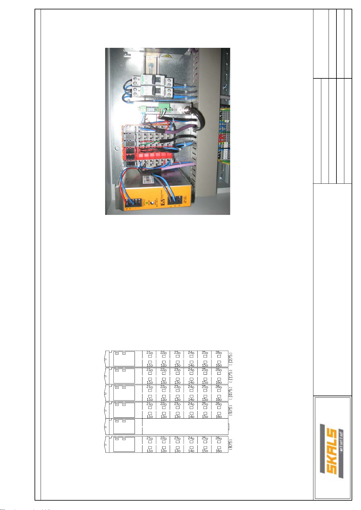
Inside cabinet Backside cabinet
Projekt t itel: Væg t 3 Render/ Weight 3 lines Sags nr: 2010-11-24
Kunde: Skals Maskinfabrik
Side titel: Mekanisk PLC
Side reference:
Side reference beskrivelse:
Page 56

15/4
2512/10/2012
25
27
1:1
7
7
6/1
6/3
6/3
6/4
6/5
9/3
9/8
9/10
11/3
11/4
2/5
3/5
4/5
1/1
1/7
2/6
3/6
4/6
10/8
1/3
2/4
2/8
PC|SCHEMATIC Automation
Page
Previous page:
Next page:
Number of pages:
Last printed:
Last correction:
Page rev.:
Project rev.:
Wexøe A/S Double feed through terminal
ZDK 1.5 167430
X20BT 9300
X20D02633
X20CS 1030
X20DO 2322
X20BT 9400
Relay, plug-in, 5-pin, SPDT, 10A, mech & LED indicators, coil suppress
Relay, plug-in, 5-pin, SPDT, 10A, mech & LED indicators, coil suppress
OMRON Electronics A/S
---
OMRON Electronics A/S
OMRON Electronics A/S
G2R-1-SNDI 24DC
G2R-1-SNDI 24DC
Telemecanique Main switch disconnector 20A 3P
Telemecanique
VBF01
OPS1050.1
4PP045.0571-062
4PP045.0571-062
4PP045.0571-062
Type SPSS 150kg
Appr. (date/sign.)
Constructor (project/page)
Drawing no.:
Project no.:Project title:
DCC: Scale:
Components list
Customer:
Vægt_2 Render_V2 12/10/2012
Page title:
Filename:
Page ref.:
Vægt 3 Render/ Weight 3 lines 26
Bus Dark Violet
4008190444884
-9X Weidmüller
Component Part no. ManufacturerPos. Type Source Description Position
1
10065160
-T305
20
10065160
-T405
-T1008
21
22
-W103
23
-W205
24
-W207
25
-W20826 Bus Dark Violet 3/8
-W30527 3/4
-W40528 4/4
3389110201000
10088190
-T107
18
10065160
-T205
19
10088050
10088080
10088100
10088070
10088060
-EHT_1
-IF4_4
-K601
-K602
-K603
-K604
-K605
-K903
-K908
2
3
4
5
6
7
8
9
10
4536854407956
-K910
-K1103
11
12
4536854407956
-M205
-K1104
13
-M305
14
15
-M405
16
-Q0101
17
Page 57

8/2
10/7
13/4
13/5
13/8
13/10
13/12
15/3
15/7
1/8
15/2
1/1
1/1
15/8
15/9
10/4
13/5
1/6
1/6
1/13
1/3
1/3
1/8
2512/10/2012
26
1:1
7
PC|SCHEMATIC Automation
Page
Previous page:
Next page:
Number of pages:
Last printed:
Last correction:
Page rev.:
Project rev.:
Feed through terminal
Double feed through terminal
Wexøe A/S
---
Weidmüller
Weidmüller
ZDU 2,5
ZDK 1.5 167430
Feed through terminal
---
Weidmüller
ZDU 16 174523
Double feed through terminal
PE terminal
---
---
Weidmüller
Weidmüller
ZDK 1.5 167430
ZPE 16 174525
Double feed through terminal
---
Weidmüller
ZDK 1.5 167430
RS185 69314011 4140
X67DI1371
Mcb iDPN 1P+N C10
Merlin Gerin
Merlin Gerin
21556
1492-RFB424
Mcb iDPN 1P+N C10
Merlin Gerin
Merlin Gerin
21556
Under voltage release MZ528N
Mushroom pushbutton red Ø30, push-turn
Feed through terminal
HAGER
Telemecanique
Wexøe A/S
HAGER
Telemecanique
Weidmüller
MZ528N
ZB4BS44
ZDU 2,5
4PP045.0571-062
Drawing no.:
Project no.:Project title:
DCC: Scale:
Components list
Vægt 3 Render/ Weight 3 lines 27
Customer:
Page title:
Appr. (date/sign.)
Constructor (project/page)
Vægt_2 Render_V2 12/10/2012
Filename:
Page ref.:
4008190444884
4008190444884
10088220
10088110
3303430215561
5703847533049
3303430215561
3250614565144
3389110888706
4008190077969
-X1
---
10088010
D410
4008190077969
4008190444884
4008190996765
4008190996789
-X43
-X101
-X1004
-X1305
-F106
-F106/1
-F113
-K103
-W802
-W1007
-W1304
-W1305
-W1308
-W1310
-W1312
-W1503
-W1507
-X1
-X1
-X10
-X10
---
Component Part no. ManufacturerPos. Type Source Description Position
---
-S103
---
---
=V1+K1
42
43
44
45
46
47
48
49
50
51
29
30
31
32
33
34
35
36
37
38
39
40
41
52
 Loading...