

Page 1
I
GB
F
ver: ott. 96 - stampato ...
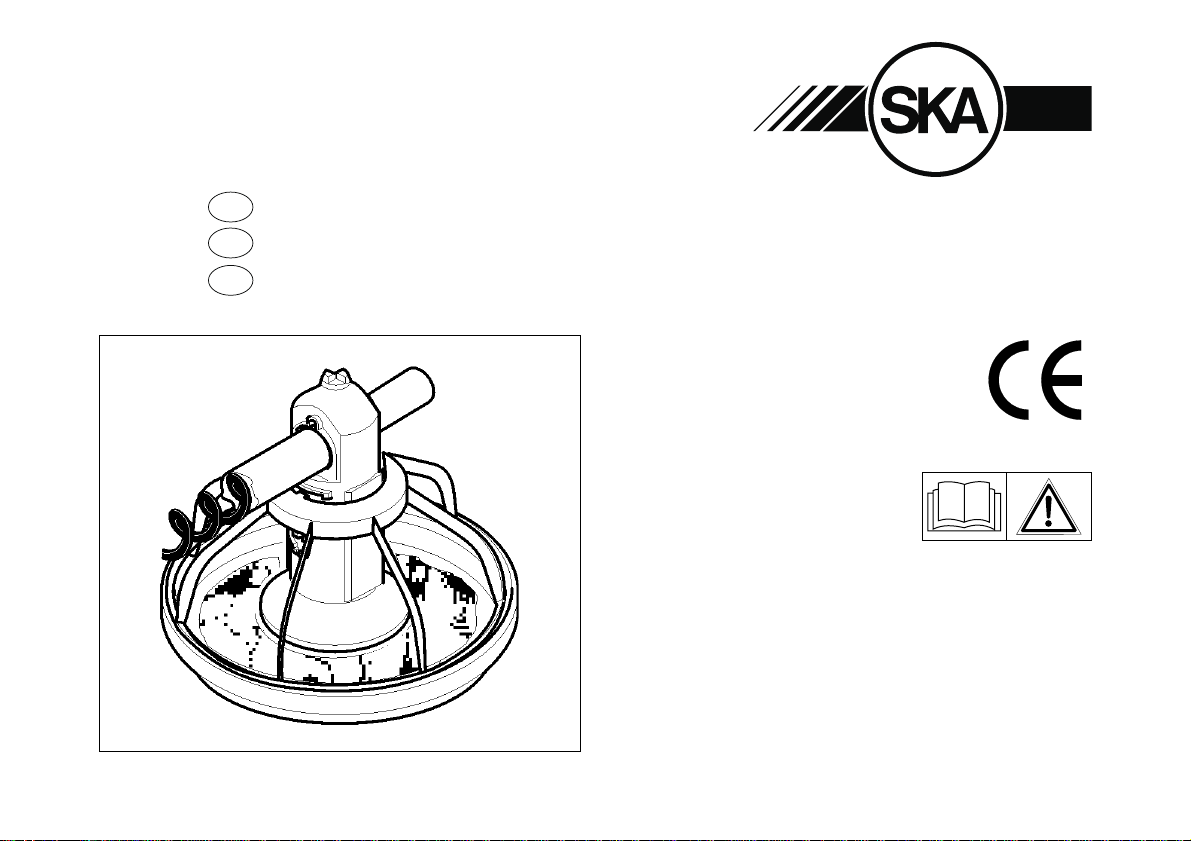
ISTRUZIONI PER IL MONTAGGIO ALIMENTATORE “GAMMA”
ASSEMBLY INSTRUCTIONS FOR THE “GAMMA” FEEDER
INSTRUCTIONS DE MONTAGE DU NOURISSEUR “GAMMA”
Prima di iniziare ad
operare, leggere
attentamente il
libretto di istruzioni
SKA S.p.a. Via Agosta, 3
Tel. +39-0444- 659700 Fax+39-0444- 659322
Attrezzature e
prefabbricati per l’avicoltura e la zootecnia.
Poultry and livestock equipment.
Equipements et préfabriqués pour l’avicolture et la
zootechnie.
36066 Sandrigo (VI) Italy
e-mail: [email protected]
http://www.ska.it
Page 2

Page 3

I
INDICE:
PREMESSA ..........................................4
NOTE TECNICHE SULLA SICUREZZA ....................4
MONTAGGIO TRAMOGGIA ............................10
MONTAGGIO LINEA DI ALIMENTAZIONE .................12
PREMONTAGGIO MANGIATOIA ........................16
INSERIMENTO TUBI DI SCARICO .......................16
MONTAGGIO TUBAZIONE .............................20
MONTAGGIO DELLE MANGIATOIE......................22
INSERIMENTO SPIRALE ..............................24
TENSIONE SPIRALE .................................26
APPLICAZIONE ANTISOSTA ...........................28
AVVIAMENTO DELLA MANGIATOIA .....................28
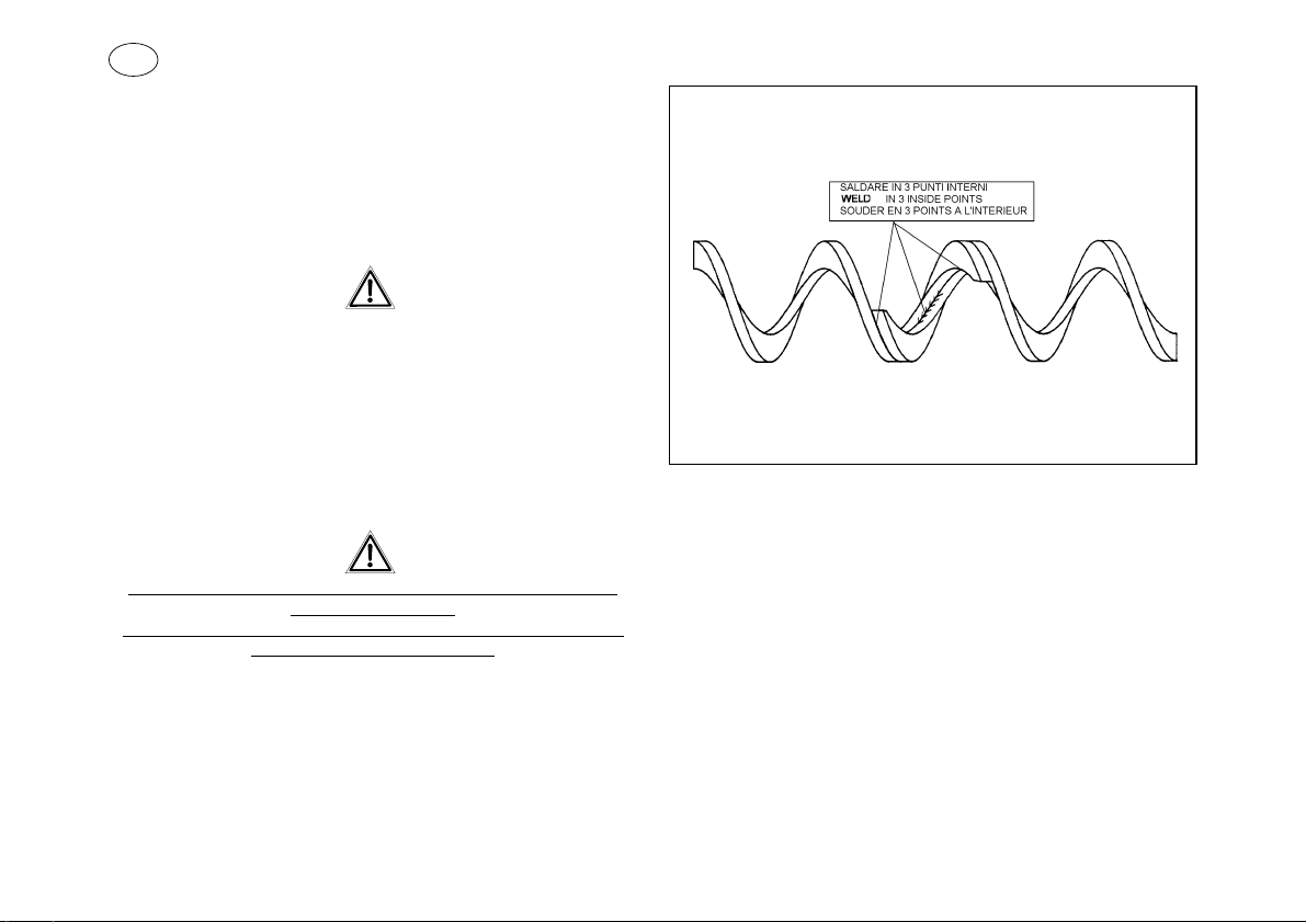
SALDATURA SPIRALE ................................32
MANUTENZIONE.....................................34
SCHEMAELETTRICOPERILCOMANDODEIMOTORI.......36
RICAMBI............................................37
GB
CONTENTS:
MEMORANDUM.......................................5
TECHNICAL NOTES ON SAFETY ........................5
HOPPER ASSEMBLY .................................11
INSTALLATIONOFTHEFEEDINGLINE ...................15
PREASSEMBLYOFTHEFEEDPAN......................17
INSERTIONOFTHEDROPTUBES.......................17
ASSEMBLY OF THE PIPES ............................21
FEED PAN ASSEMBLY ................................23
PLACEMENT OF THE AUGER ..........................25
AUGER TENSION ....................................27
ANTIPERCH INSTALLATION ...........................29
STARTING OF THE SYSTEM ...........................29
WELDING OF THE AUGER.............................33
MAINTENANCE ......................................35
WIRINGDIAGRAMFORMOTORSCONTROL ..............36
SPARE PARTS ......................................37
F
INDEX:
PREMISSE...........................................5
NOTESTECHNIQUESSURLASECURITE..................5
ASSEMBLAGE DE LA TREMIE..........................11
ASSEMBLAGEDELALIGNED’ALIMENTATION ............15
PREASSEMBLAGE DE LA MANGEOIRE..................17
MONTAGE DES DESCENTES ..........................17
MONTAGE DES TUBES ...............................21
ASSEMBLAGE DES MANGEOIRES ......................23
INSTALLATION DE LA SPIRAL..........................25
TENSION SPIRAL ....................................27
INSTALLATION ANTIPERCHAGE........................29
DEMARRAGE DE LA MANGEOIRE ......................29
SOUDAGE DE LA SPIRAL .............................33
MANUTENTION ......................................35
SCHÉMA ELÉCTRIQUE POUR LE CONTRÔLE
DES MOTEURS ......................................36
PIECES DE RECHANGE ...............................37
Page 4
I
PREMESSA:
Gentile Cliente Vi ringraziamo per aver scelto i nostri prodotti, siamo
sicuri che resterete soddisfatto per la qualità e le prestazioni della
mangiatoia GAMMA.
Prima di iniziare il montaggio controllate se la spedizione è completa,
aprite tutte le scatole e verificate che non vi siano parti danneggiate
durante il trasporto.
Vi consigliamo di leggere attentamente il presente manuale,
in particolar modo le note tecniche sulla sicurezza.
Idati, le notizie ed i suggerimenti, benchè redatti conogni cura, hanno
valore soltanto indicativo e non impegnativo.
LaSKA S.p.A. pertanto nonsi assume nessuna responsabilitàcirca la
loro utilizzazione e i risultati ottenuti dal loro impiego.
LaSKA S.p.A. perseguendo una politica di continuo miglioramento, a
suo giudizio e anche senza preavviso siriserva di apportare qualsiasi
modifica ai prodotti descritti.
NOTE TECNICHE SULLA SICUREZZA :
L’alimentatore automatico per broilers “GAMMA” è stato costruito in
conformità con le vigenti norme di sicurezza, DPR n.547 del 27 aprile
1957 e in particolare seguendo i principi della Direttiva CEE 89/392 e
91/368.
Nonostante ciò è bene richiamare alla vostra attenzione alcuni punti
molto importanti.
SKA / 4
Page 5
GB
MEMORANDUM:
Dear Customer, we thank you for choosing our product. We are sure
you will be satisfied with the quality and the performance of the
“GAMMA” pan feeding system.
Before assembling, please check if the delivery is complete andif any
part has been damaged during transport.
F
PREMISSE:
Cher Client, nous vous remercions d’avoir choisi nos produits, nous
sommes sûrs que vous resterez satisfaits de la qualité et de la
performance de la mangeoire “GAMMA”.
Avant de commencer le montage, vérifier si la livraison est complète,
ouvrir toutes les boîtes et vérifier s’il y a des pièces endommagées
pendant le transport.
We suggest reading this manual carefully, particularly the
technical notes on safety.
The information, comments and proposals presented, although
studied with great care, are suggestions and are not in any way
compulsory.
SKAS.p.A. therefore does not accept any responsibility for the results
obtained through their use.
Furthermore SKA S.p.A. reserves the right to make any necessary
modification to the described products and without notice.
TECHNICAL NOTES ON SAFETY:
The automatic feeder for broilers GAMMA has been designed
according to current Italian safety laws DPR n.547 of 27 April 1957
and in particular following the principles of the EEC Directives 89/392
and 91/368.
In spite of this, we would like to bring the following very important
points to your attention.
Nous vous conseillons de lire avec attention ce manuel, en
particulier les notes techniques sur la sécurité.
Lesinformations, noticeset suggestions,bien querédigées avecsoin,
ont une valeur seulement indicative qui n’engage pas.
La SKA S.p.A. n’assume aucune responsabilité en ce qui concerne
leur installation et les résultats obtenus de leur utilisation.
La S.p.A., une politique d’amélioration continue, selon son avis et
sans préavis se réserve le droit d’apporter n’importe quelle
modification aux produits décrits.
NOTES TECHNIQUES SUR LA SECURITE:
L’alimentateurautomatique pourbroilers GAMMA aété construitavec
les règles de sécurité en vigeur DPR n.547 du 27 Avril 1957 et, en
particulier,suivantlesprincipesdelaDirectiveCEE89/392et91/368.
Malgré cela il est bien rappeler à vote attention aucuns points très
importants.
GAMMA / 5
Page 6
I
L’attrezzatura qui di seguito descritta è un insieme di componenti che
vannoassemblati direttamentenel luogodove verranno utilizzati.Ogni
singolocomponente è stato costruito tenendo bene in considerazione
la sicurezza degli operatori che utilizzeranno l’alimentatore, tuttavia
operazionidi assemblaggio mal eseguite possono compromettere sia
il funzionamento del sistema che la sicurezza delle persone che
verranno a contatto con l’impianto.
Per questo motivo vi consigliamo di assicurarvi che il montaggio ed
i collegamenti elettrici vengano effettuati da personale qualificato.
L’alimentatore “GAMMA” è stato progettato esclusivamente per il
trasporto e la distribuzione di mangime nell’ambito di allevamenti
avicoli; pertanto è severamente vietato utilizzarlo ( interamente o
anche nelle sue parti ) per scopi diversi senza la preventiva
autorizzazione del costruttore.
L’alimentatore a spirale può servire per trasportare mangime del tipo
avicolo, farine, pellettati di dimensioni non superiori a mm 12 di
lunghezza e mm 5 di diametro, sbriciolati, granaglie (senza però
garantire l’integrità delle stesse).
E’ fatto divieto di utilizzare il presente alimentatore per trasportare
liquidi, materiali semisolidi, polpe di barbabietola, alimenti destinati
agli umani, scarti di macello, residui dell’industria alimentare e
conciaria, animali vivi, polveri metalliche e inerti e quant’altro possa
danneggiare o intasare il tubo e la spirale.
Vi ricordiamo inoltre che lasciare del mangime fermo all’interno del
tubo per troppo tempo può alterare il corretto funzionamento del
trasportatore.
SKA / 6
Page 7
GB
The equipment described is a group of components which should be
assembled directly in the place of use. Every single component was
manufacturedkeeping in mind the safety of the operators who use the
feeder.
Please note that bad assembly can compromise both the working of
the system and the safety of the persons who come into contact with
the installation.
Therefore, we advise you to ensure that the assembly and electrical
connections will be done by authorised and qualified personnel.
The GAMMA feeder was planned for the transport and the
distribution of feed in poultry rearing farms; it is therefore forbidden
to use it ( the whole system or its components ) for other purposes
without the authorisation of the manufacturer.
F
composant a été construit en tenant compte de la sécurité des
operateurs qui utiliseront l’alimentateur, toutefois les opérations
d’assemblage mal exécutés peuvent compromettre soit le
fonctionnementdusystèmesoit la sécurité des personnes que seront
en contact avec l’installation.
Pour ces raisons nous vous conseillons de demander que
l’assemblage et les branchements eletriques, soient faits toujours
par personnel autorisé et qualifié.
L’alimentateur GAMMA a été conçu pour le transport et la
distribution d’aliment dans les limites des élevages avicoles;
pourtant il est sévèrement interdit de l’utiliser pour des buts
différents sans l’autorisation du constructeur.
The auger feeder can beused to transport poultry feed,flours, pellets
which have a diameter of less than 5 mm and are no longer than 12
mm,grain(without,however,guaranteeingtheintegrityofthesame).
It is forbidden to use the present feeder for the transport of liquids,
semisolid materials, by-product of sugar beet, food destined for
human use, slaughter house waste, feed industry and tannery
residues, live animals, inert and powdery metals and anything else
that could damage or clog the pipe and the auger.
We recommend that you avoid in any way feed retention inside the
pipe for long periods becausethis could seriously spoil the working of
the system.
L’équipementdécrit de suite est un ensembledecomposants qui vont
s’assemblés directement dans le lieu ou ils seront utilisés. Chaque
L’alimentateur à spiral peut servir pour le transport d’aliment du type
avicole, farine, granules et cubes avec dimensions inférieur à mm 12
de longueur et mm 5 de diamètre, grains (sans garantir l’integrité
d’elles-mêmes).
Il est fait interdit utiliser cet alimentateur pour le transport des
liquides, des materiels semisolides, des aliments destinés aux
humains, des éliminations des abattoirs, des restes de l’industrie
alimentaire et de la tannerie, animaux vifs, poudres metalliques et
inertes etc...
Nous conseillons d’eviter le retenu d’aliment dans le tube pour
beaucoup de temps; faisant ça peut détraquer le fonctionnement du
système.
GAMMA / 7
Page 8
I
La SKA declina ogni responsabilità per eventuali danni a persone o
cose derivanti da un non autorizzato utilizzo dell’alimentatore
“GAMMA”, da un non corretto montaggio delle parti meccaniche o
elettriche nonchè dalla rimozione o manomissione delle protezioni.
Dichiarazione CE di conformità per macchine.
(Direttiva 89/392/CEE, Art. 4.2 e Allegato II, parte B)
Divieto di messa in servizio
Indirizzo: Via Agosta 3
Dichiara che il prodotto:
ALIMENTATORE AUTOMATICO “GAMMA”
è costruito per essere incorporato in una macchina o per essere
•
assemblato con altri macchinari per costruire una macchina
considerata dalla Direttiva 89/392/CEE, come modificata;
non é dunque conforme in tutti i punti alle disposizioni di questa
•
Direttiva;
e inoltre dichiara che non è consentito mettere in servizio il
macchinario fino a che la macchina in cui sarà incorporato o di cui
diverrà componente sia stata identificata e ne sia stata dichiarata la
conformità alle condizioni della Direttiva 89/392/CEE ed alla
legislazione nazionale che la traspone, vale a dire fino a che il
macchinariodi cuialla presentedichiarazione nonformiun complesso
unico con la macchina finale.
Sandrigo 01/01/96
Fabbricante: SKA S.p.A.
36066 Sandrigo (VI) Italy
SKA S.p.A.
MARA BORRIERO
SKA / 8
Page 9
GB
F
SKA declines any responsability for eventual damages to persons
and objects arising from the non-authorised use of the feeder
GAMMA, by the incorrect assembly of the mechanical or electrical
Manufacturer: SKA S.p.A.
Address: Via Agosta 3
Herewith declares that:
“GAMMA” AUTOMATIC FEEDER
•
•
andfurthermoredeclaresthatitis notallowed toput themachinery into
service until the machinery into which it is to be incorporated or of
which it is to be a component has been found and declared to be in
conformity with the provisions of Directive 89/392/EEC and with
national implementing legislation, i.e. as a whole, including the
machineryreferredtointhisdeclaration.
Sandrigo 01/01/96
parts or from the removal of the protections .
(Directive 89/392/CEE, Art. 4.2 and Annex II, sub B)
36066 Sandrigo (VI) Italy
is intended to be incorporated into machinery or to be assem
bled with other machinery to constitute machinery covered by
Directive 89/392/EEC, as amended;
does therefore not in every respect comply with the provisions of
this directive;
Declaration by the manufacturer
Prohibition to put into service
-
SKA S.p.A.
MARA BORRIERO
La SKA decline toutes responsabilités pour d’eventuels dommages
à des personnes ou choses, qui derivent d’une utilisation pas
autorisé de l’alimentateur GAMMA ou d’un assemblage incorrecte
Fabricant: SKA S.p.A.
Adresse: Via Agosta 3
Déclaire ci-après que:
NOURISSEUR AUTOMATIQUE “GAMMA”
est prévue pour etre incorporée dans una machine ou etre as
•
semblée avec d’autres machines pour constituer une machine
couverte par la directive 89/392/CEE, modifiée koneen;
•
n’est donc pas conferme en tout point aux dispositions da direc
tive;
etdeclare par ailleurs qu’il est interdit de mettre la machine en service
avant que la machine dans laquelle elle sera incorporée ou dont elle
constitue une parte ait été considérée et declarée conforme aux
dispositions de la Directive 89/392/CEE et aux législations nationales
la trasponsant, c’est-à-dire format un ensemble incluant la machine
concernée par la présente déclaration.
Sandrigo 01/01/96
des parties mecaniques ou électriques.
Declaration du fabricant
(Directive 89/392/CEE, Article 4.2 et Annex II,
Chapitre B)
Interdiction de mettre en service
36066 Sandrigo (VI) Italy
-
-
SKA S.p.A.
MARA BORRIERO
GAMMA / 9
Page 10
I
MONTAGGIO TRAMOGGIA:
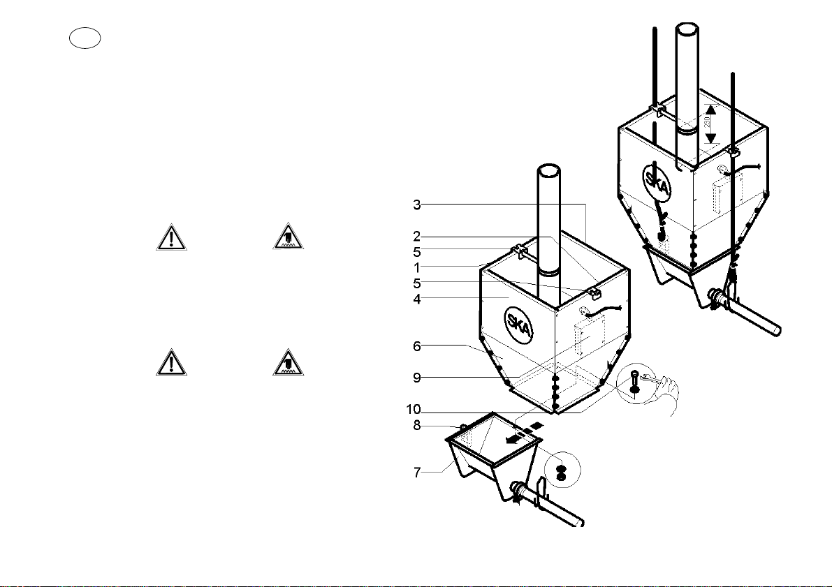
La tramoggia viene assemblata unendo le pareti (1.2.3.4) in modo da
formare un corpo unico mediante le viti e i dadi in dotazione.
All’esternodella tramoggia vengono fissati condelleviti i ganci (5) che
servono per il sostegno della sovrasponda vedi fig. A.
Sudi unlato esternodel pozzettofissareper mezzodelle vitil’apposito
gancio (8).
Su di una parete della sovrasponda sono previsti dei fori per il
fissaggio del pressostato (9).
A montaggio eseguito la tramoggia (6) viene inserita tramite apposite
feritoie di scorrimento sopra al pozzetto (7).
Il bloccaggio della tramoggia sul pozzetto va fatto con
vite (10) dado e rosette fig A.
Questa vite non deve essere rimossa.
La rimozione di questa vite permette l’accesso alla spirale la quale
può provocare ferimenti alle mani!
Nel caso l’impianto sia fornito con tramoggia bassa (art
4572000) e’ necessario montare la rete di protezione usando le
apposite viti.
SKA / 10
Fig. A
Page 11
GB
HOPPER ASSEMBLY:
Theextension hopper is assembledby joiningthe walls(1.2.3.4)soas
to form a single body.
On the outside of the tank the hooks (5) supporting the extension
hopper are fixed by means of screws (see drawing A).
On one outside wall of the boot, fix the appropriate “C” hook (8) using
the special screws.
Holes to fix the pressure switch (9) have been provided in the
extension hopper.When the assembly has been carried out, the
extension hopper (6) is connected through special slip slits over the
boot (7).
F
ASSEMBLAGE DE LA TREMIE :
La trémie est montée en assemblant les parois (1.2.3.4), de façon à
former un corps unique avec les vis et les écrous en dotation.
A l’extérieur du réservoir fixer, par moyen des vis, les crochets (5)qui
servent à soutenir la trémie (voir dessin A).
Sur la partie extérieure du boitard, fixer le crochet (8) approprié par
des vis.
Sur une paroi de la trémie on a prévu des trous pour le fixage du
palpeur à membrane (9).
Lorsqu’ona achevé l’assemblage, la trémie (6)est inserée par moyen
des fentes de glissement sur le coffre (7).
The fixing of the hopper onto the boot must be done by
(10), nut and washer ill. A.
This screw must not be removed.
Removing this screw allows the access to the auger which could
hurt your hands!
In case the system is provided with a low hopper (art 4572000), it is
necessary to mount the protection mesh by using the special
screws.
screw
Le blocage des deux parties est effectué par moyen de
(10), écrou et rondelle (dessin A).
Cette vis ne doit pas être enlevée.
L’enlèvement de cette vis permet l’àcces à la spirale qui peut
provoquer des blessures aux mains!
Dans le cas où l’installation soit pourvue d’une trémie basse (art
4572000), monter le filet de protection
à l’aide de ses vis.
vis
GAMMA / 11
Page 12
I
MONTAGGIO LINEA DI ALIMENTAZIONE:
Essendo una linea sospesa con un verricello (20)per il sollevamento,
è necessario individuare il punto dove si vuole applicare il verricello
(normalmente in centro rispetto alla lunghezza della linea ).
Il verricello viene fissato saldamente alla travatura, eventualmente si
costruiscono in loco i relativi sostegni.
Alle estremità vengono fissate allo stesso modo del verricello delle
carrucole del diametro di 80 mm (21). Utilizzare due carrucole
diametro 80 mm per fare il rinvio, se previsto.
Dopo aver fissato verricello e carrucole, viene fatta passare la fune
principaledidiametro6mm(22)cheservirà asostenere tuttala linea.
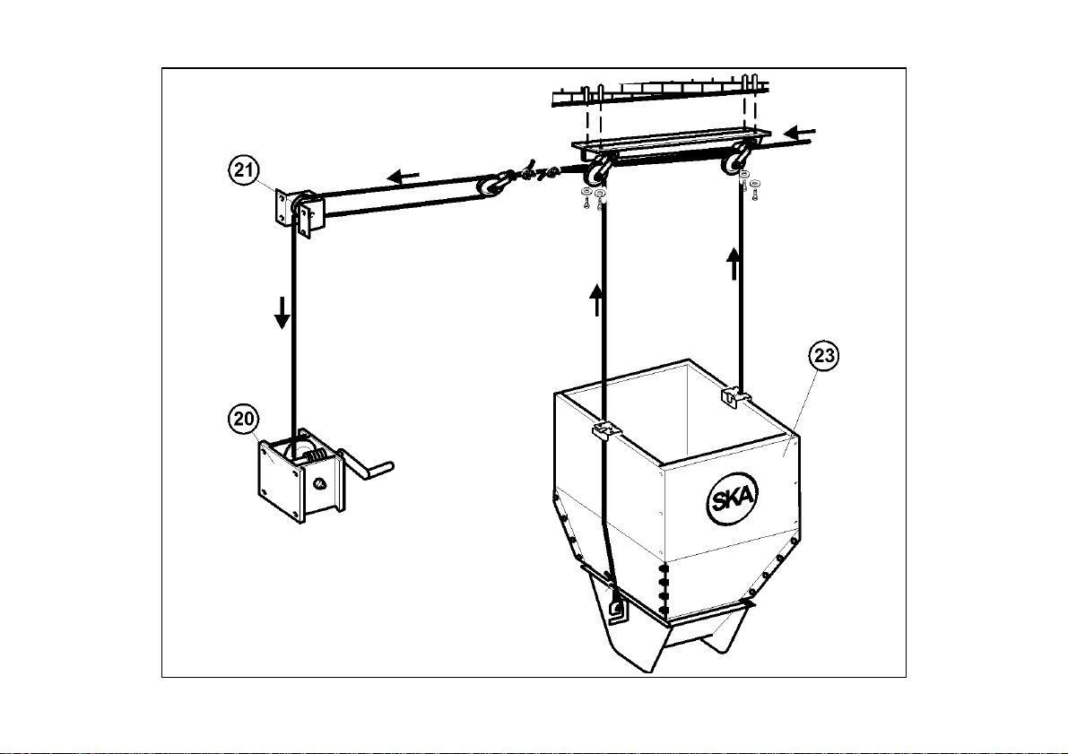
Peril posizionamento edil fissaggio delle funialla tramoggia (23)edal
gruppo di traino (24) vedere fig. B eC.
Su tutta la lunghezza della linea vengono fissate al soffitto delle
carrucole intermedie (25) del diametro di 40 mm in plastica, ogni 3
metri (max 4 metri
carrucole in plastica ma esternamente ad esse, ad una
).
La fune principale non deve essere passata dentro le
distanza di pochi centimetri.
SKA / 12
Page 13
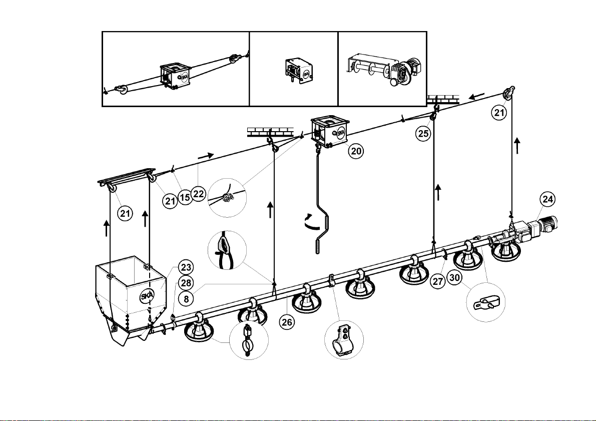
fig. B
GAMMA / 13
Page 14
SKA / 14
fig. C
Page 15
GB
INSTALLATION OF THE FEEDING LINE:
F
ASSEMBLAGE DE LA LIGNE
D’ALIMENTATION:
Asit isa linesuspended by awinch (20) for lifting,it isnecessary to find
theexact point where to place the winch (generallyin the middle of the
line).
The winch is fixed firmly to the truss, and if needed, the necessary
supports are built on place.
At the ends some pulleys diameter 80 mm (21) are also fixed, in the
same way as the winches. Use two pulleys Ø 80 mm to form the belt
gear, if provided.
Afterfixing winchand pulleys,the ropes diameter6 mm(22) holding all
the lines are let in.
For the positioning and fixing of ropes to the hopper (23) and to the
drive unit (24) see drawing B e C.
Along the line, every 3 metres (max 4 metres), intermediate plastic
pulleys (25) diameter 40 mm are placed.
The main cable must not be passed through the plastic
pulleys but must be laid outside them, at a distance of a few
centimetres.
Puisqu’ils’agit d’une ligne suspendue par moyen d’un treuil (20),pour
le soulèvement il est nécessaire déterminer le point d’application du
treuil (généralement au milieu de la longueur de la ligne).
Le treuil est fixé solidement à la charpent; sur demande on construit
sur place les appuis.
Auxextrémités on fixe,de la mêmefaçon qu’on afait pour letreuil, des
poulies du diamètre 80 mm (21). Utiliser deux treuils de diamètre 80
mm pour faire le renvoi si prevu.
Après avoir fixé poulie et treuil, on fait passer les cables diamètre 6
mm (22)qui devront soutenir toute la ligne.
Pour positionner et fixer les cables à la trémie (23) et au groupe
d’entrainement (24), voir dessin B e C.
Tous le long de la ligne, chaque 3 mètres (max. 4 mètres
inserer des poulies intermédiares (25) de diamètre 40 mm en
plastique.
La cable principale ne doit pas être passé dans les treuils en
plastique mais à l’extérieure, à une distance de peu de
centimètres.
), on doit
GAMMA / 15
Page 16
I
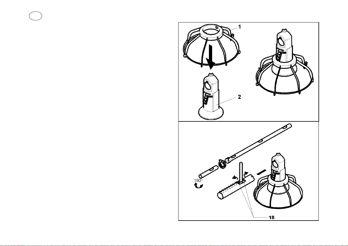
PREMONTAGGIO MANGIATOIA:
Prima di procedere con il collegamento dei tubi è necessario
premontare la griglia (1) sullo scarico (2) fig.D.
INSERIMENTO TUBI DI SCARICO:
Itubi zincati vengonoforniti a lunghezzestandard, 6 metrio 3 metri;su
ognitubo vengonoposizionate rispettivamente8/6 mangiatoieoppure
4/6 mangiatoie, a seconda della versione.
I fori sui tubi servono per l’uscita del mangime, mentre i naselli (18)
hanno lo scopo di bloccare le mangiatoie in corrispondenzadel foro e
vanno ripiegati come in fig.E.
Prendere i tubi zincati (26) e partendo dalla tramoggia (23) disporli a
terra per tutta la lunghezza dell’impianto con i relativi giunti e viti di
fissaggio (27) fig. B.
Accanto ad ogni tubo, disporre tanti scarichi GAMMA con griglia,
quanti sono i fori di uscita del mangime.
Dopo aver infilato gli scarichi sul tubo, disporli sopra i naselli e far
ruotare di 180° ogni scarico in modo che vada adincastrarsi tra idue
naselli.
Fig. D
SKA / 16
Fig. E
Page 17
GB
PREASSEMBLY OF THE FEED PAN:
Beforeconnecting the pipesit is necessary tomount the grid(1)onthe
drop tube (2) fig. D.
F
PREASSEMBLAGE DE LA MANGEOIRE:
Avantdemonterlestubes,infilerrlesgrilles(1)sur letube (2)fig. D.
INSERTION OF THE DROP TUBES:
The zinc plated pipes in standard lengths of 6 or 3 metres; 8/6
feeders or 4/3 feeders are placed on each tube according to the
version.
On every pipe there are holes for the feed exit and some nibs (18)
which block the feeders and they must be bent as per fig.E.
Take the zinc plated pipes (26) and, starting from the hopper (23),
placethem onthe groundalong thewhole lengthof theinstallation with
the corresponding joints and fastening screws (27) fig. B.
Near each pipe place on the ground some drop tubes with grid
according to the number of holes.
After inserting the drops on the pipe, place them in corrispondance
withthenibsthen turn thedrops inorder toblock themonto thepipes.
MONTAGE DES DESCENTES :
Les tubes zingués sont fournis avec une longueur standard de 6 ou 3
mètres et sur chaque tube on place 8/6 mangeoires ou 4/3
mangeoires, suivant les models.
Les trous sur le tube servent pour le sortie de l’aliment, alors que les
déclics (18) ont le but de bloquer lamangeoire encorrespondance du
trou et sont repliés comme dans les dessin E.
Prendreles tubes zingués(26) eten commençant delatrémie (23)les
mettre à terre pour tous le longueur de l’installation avec les joints
rélatifs et les vis de fixage (27) fig. B.
A côté de chaque tube, mettre des descentes GAMMA avec grille
aussi tant que les trous de sortie.
Depuisavoir infilé les descentes sur le tube, mettez-les sur les déclics
et · tourner de 180° les descentes en moyen qu’ils vont à s’encrocher
entre le deux déclics
GAMMA / 17
Page 18

I
Disporre i ganci delle griglie (19) fig. F tutte dalla stessa parte, al
fine di agevolare la pulizia delle mangiatoie.
Nel caso di due linee, è consigliabile orientare i ganci delle griglie
verso l’esterno del capannone.
Fig. F
SKA / 18
Page 19
GB
F
Arrange all hooks of the grids (19) fig. F on the same side, in order
to facilitate the cleaning of the pan feeders. In case of two lines, it is
advisable to orientate the hooks of the grids towards the outer side
of the shed.
Arranger tous les crochets des grilles (19) fig. F de la même côté,
afin de faciliter le nettoyape des mangeoirs. En cas de deux lignes,
il est conseilleable d’orienter les crochets des grilles vers l’extérieur
de la halle.
GAMMA / 19
Page 20
I
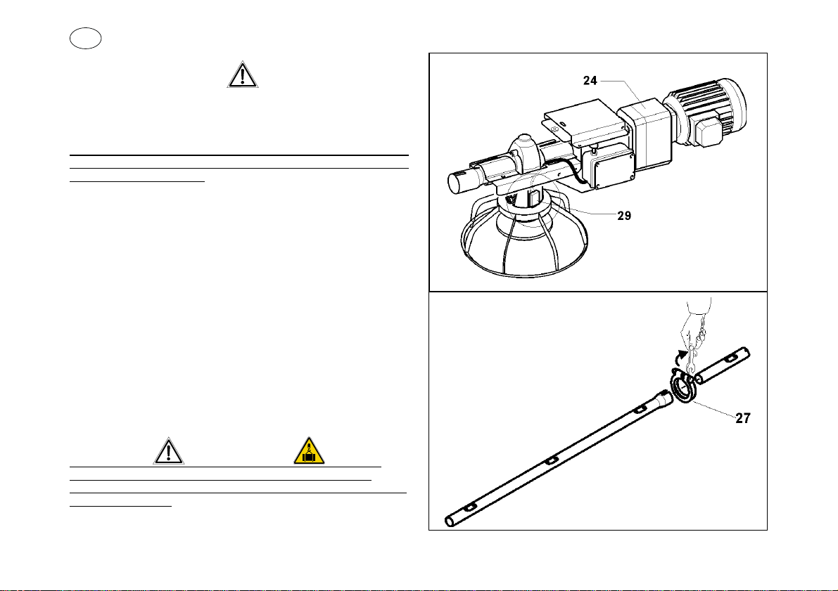
In prossimità del gruppo traino (24) deve essere montato lo scarico
con il pressostato (29) fig.G.
La stessa cosa deve essere fatta in corrispondenza dei divisori per
la pulcinaia, nel caso siano stati previsti i pressostati intermedi.
Consigliamo di tagliare circa 75 cm dall’ultimo tubo e di sostituirlo con
quello con foro maggiorato, altrimenti la linea avrà una lunghezza
superiore a quella prevista.
MONTAGGIO TUBAZIONE(fig.BeH):
Completatoilmontaggio dei tubi con gli scarichi, cominciare ad unire i
tubi zincati tra di loro partendo dalla tramoggia e fissarli con le relative
fascette (27) fig. B.
Sulla lunghezza della linea si possono inserire, a seconda delle
esigenze, più mangiatoie con pressostato.
Si può inoltre disinserire il pressostato quando si utilizza la linea in
tutta la sua lunghezza.
Fatto questo far passare le cordine in nylon, che avrete fissato sulla
fune principale con i morsetti (15) e fatto passare per le carrucole in
plastica, attorno alla linea.
Utilizzate le piastrine di regolazione (8) come in fig. B.
Dopo aver messo in tensione le cordine sollevare con il verricello in
modo da poter applicare le rimanenti parti lavorando in posizione
comoda.
Verificate la solidità dei fissaggi del verricello e delle carrucole!
La linea è un carico sospeso pertanto occorre usare cautela.
Una volta sollevata, per un buon funzionamento è importante che la
linea sia orizzontale.
Fig. G
Fig. H
SKA / 20
Page 21
GB
F
The drop with the pressur switch (29) must be assembled close to
The same thing must be done where the partitions for the brooding
areas are, if the pressure switches in that positions were planned.
We suggest cutting about 75 cm from the last pipe installed and
replacing it with the piece of pipe with the oversize hole, otherwise the
line will be longer than the planned length.
the drive unit (24), fig.G.
ASSEMBLY OF THE PIPES(fig.B e H):
Once completed these operations, begin connecting the pipes,
starting from the hopper; fix them with their joints (27) fig. B.
Along the length of the line more feeders with pressure switch can be
inserted according to what is needed.
Youcan alsodisinsert thepressure switchwhen thewhole lineis being
used.
Insertthe nylon cables, after having fixed them onto the main cable by
meansoftheclamp(15),intothe plasticpulleys andaround thepipes.
Block the cable using the cable adjuster (8) as per fig. B.
After stretching the cables, lift the line with the winch so as to have the
opportunity of applying the missing items in a more comfortable
position.
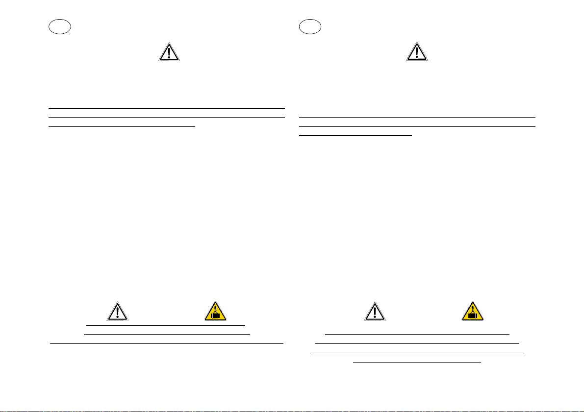
Verify the solidity of pulleys, winch and cables
The line is a suspended load so be very careful.
Once lifted, for good operation the line must be perfectly horizontal.
!
En proximité du groupe d’entrainement (24) la descente avec
palpeur à membrane (29) doit être installée, fig. G.
La même chose doit être fait en correspondance aux diviseurs de la
poussinière, en cas qu’ils aient été prevus les palpeurs
intermediares.
Nous conseillons de couper approx. 75 cm du dernier tube et de le
remplacer avec le tube avec trou majoré, sinon la ligne aura une
longueur supèrieure de ça prevu.
MONTAGE DES TUBES (fig.BeH):
Une fois completé l’assemblage des tubes avec descente, vous
pouvez commencer à joindre les tubes zingués entre eux, en
commençantde latrémie, et deles fixer avecles bandes rélatives(27)
fig. B.
Sur la longueur de la linge on peut inserer, selon les exigences, plus
mangeoires avec palpeur. On peut aussi disinserer le palpeur quand
on utilise la longueur complète de la ligne.
Faitça, faire passer les cordelettes de nylon, que vous avezfixé sur le
cable principal avec les serre-cables (15) et fait passer pour les
poulies en plastqiue, autour de la ligne. Utiliser les plaquettes de
regulation (8) comme fig. B.
Daprès avoir mis en tension les cordelettes, soulever avec les treuils
pour pouvoir appliquer les parts restants, en travaillant en position
confortable.
Verifier la solidité des fixages du treuil et des poulies.
La ligne est une charge suspendue qu’ on doit utiliser avec
prudence.Une fois soulevé, pour un bon fonctionnement il est
important que la ligne soit horizontal.
GAMMA / 21
Page 22
I
MONTAGGIO DELLE MANGIATOIE:
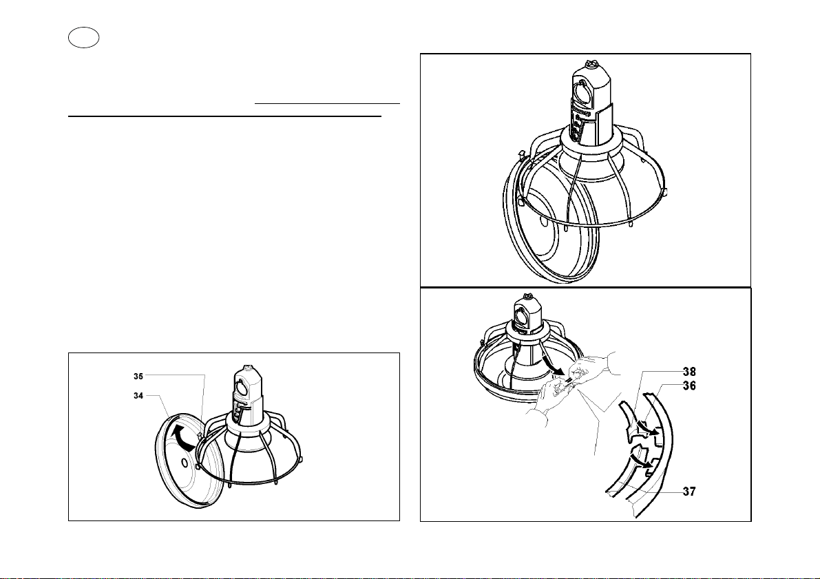
Agganciare il piatto alla griglia infilando il piatto tramite la feritoia (34)
sulgancio(35) della griglia stessa fig.I. Eseguire l’operazionein modo
che la feritoia del piatto segua il profilo del gancio senza forzare.
Una volta che il gancio della griglia con il relativo dente sono entratti
nella feritoia il piatto è agganciato e si trova nella posizione di “fine
ciclo” per le operazioni di pulizia fig. L.
Comprimere ora le due alette della griglia che sono diametralmente
opposte al gancio fig. M, contemporaneamente accompagnare il
piattoverso la grigliafino a chelagriglia stessa siincastri nel piattoper
mezzo dei denti (36).
Assicurarsi che il bordo antispreco (37) si adatti perfettamente al
bordointerno delpiatto, dopodichè farscattare i “bottoncini”(38)perla
chiusura di sicurezza della griglia.Una volta che questi “bottoncini”
sono scattati e sono aggangiati nella loro sede, il montaggio della
mangiatoia può definirsi ultimato.
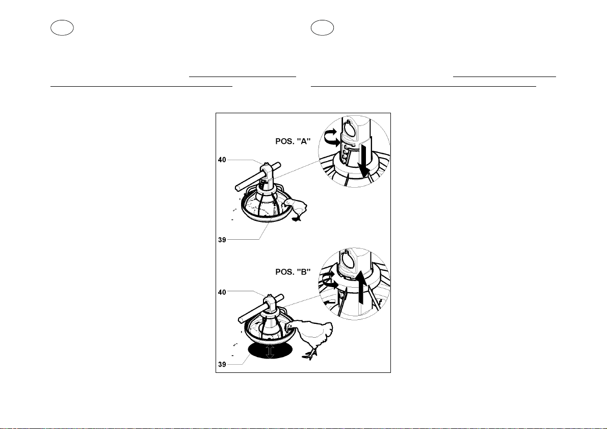
Terminataquesta fase mettere tuttele mangiatoie nella pos.“A” fig.N.
Per fare questo ruotare la griglia (39) rispetto allo scarico (40);
posizionare la griglia nell’ultima tacca in basso dello scarico.
Allafine del ciclo di crescita, quando i pulcini saranno diventati polli, si
dovrà fare rif. alla 1a tacca superiore dello scarico, pos. “B” fig. N.
Fig. L
SKA / 22
Fig. M
Fig. I
Page 23
GB
FEED PAN ASSEMBLY:
Hook the pan to the grid while inserting the pan onto the hook (35)of
thegrid itself through the slot (34) fig. I.Carry out the operation so that
the pan slit follows the hook profile without forcing.
Once the hook of the grid withthe relativetooth have entered the slot,
the plate is hooked onto the grid and is in the “end of cycle” position,
ready for cleaning fig. L.
Press the two wings of the grid which are
diametrically opposite the hook fig. M and at
the same time bring the pan towards the grid
until it is caught in the pan by the teeth (36).
Ensure that the antiwaste rim (37) fits
perfectly on the inside rim of the pan, then
snap shut the “buttons” (38) which securely
close the grid.Once these “buttons” have
snapped and are inside their hole, the
assembly of the feed pan is complete.
Now put all the pans in the “chick position”.
After having completed this phase put in “A”
position fig. N allpan feeders. Todo this slew
the grid (39) with reference to drop tube (40);
settle the grid in the lowest notch of the drop
tube. At the end of growth cycle, when the
chiks will have grown up (into chicken), it will
be necessary to settle the grid in the highest
notch of the drop tube, pos. “B” fig. N.
F
ASSEMBLAGE DES MANGEOIRES:
Depuisça, accrocher l’assiette à la grigle sur le ressort(35) de la grille
même, en utilisant la gravure (34). fig. I. Effectuer l’opération desorte
que la fente de l’assiette suive le profil du crochet sans forcer.
Quand le crochet de la grille avec le dent rélatif sont entrés dans la
gravure, l’assiette est accrochée à la grille et elle se trouve dans la
Fig. N
position de “fin du cycle” pour l’operation de
nettoyage fig. L.
Pousser maintenant les 2 ailes de la grigle
quesont diamètralement opposésducrochet
-dess. M, au même temps accompagner
l’assiette vers la grigle jusqu’au point que la
grigle s’emboîte dans l’assiette avec les
dents (36).
Asurer que le bord antigaspillage (37) est
aligné parfaitment au bord intérieur de
l’asiette. Depuis ça, faire jouer les “boutons”
(38)pourlafermeture desecurité dela grigle.
Quand les “boutons” sont joués et achrochés
dans leur siège le montage de la mangeoire
est complèt.
Depuis cette phase, mettre toutes les
mangeoires en position de “poussinière”.
Terminéecette phase, ilfaur placer toutesles
mangeoirs dans la position “A” fig. N. Pour
faireça, il faurtourner la grille (39)par rapport
au tube de sortie (40); positionner la grille
dansle derniercran enbas dutube. A lafin de
la période d’élevage, quand les poussins
seront devenus poulets, il faundra se
rapporter au premier crans supérieur du tube
de sortie, position “B” fig. N.
GAMMA / 23
Page 24
I
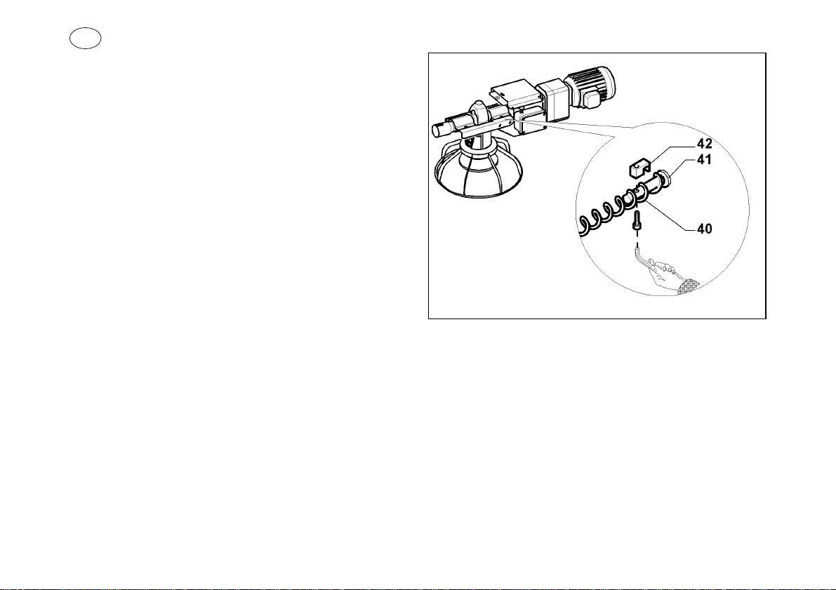
INSERIMENTO SPIRALE(fig. O):
La spirale (40) viene inserita nel tubo zincato dalla parte della
tramoggia dopo aver tolto l’alberino di testa.
Ad inserimento avvenuto la spirale fuoriesce fino ad interessare
l’alberino del gruppo di traino (41).
A questo punto inserire la spirale nel morsetto (42).
Fissare il tutto con la vite, vedi fig.O.
Fatta questa operazione di bloccaggio, la spirale deve essere
agganciata dalla parte della tramoggia, come spiegato di seguito.
Fig. O
SKA / 24
Page 25
GB
PLACEMENT OF THE AUGER(fig. O):
The auger (40) is connected with the zinc plated pipe on the hopper
side, after removing the little head shaft.
F
INSTALLATION DE LA SPIRAL(fig. O):
La spiral (40) doit être inséré dans la partie de la trémie depuis avoir
enlevé la tige de tête.
Afterconnection, the augerexit and runs alongthe drive unit shaft(41)
to the end.
Atthispoint insert the auger in the holdfast (42) and fix with the screw,
see drawing O.
After accomplishing this blocking operation, the auger must be
hooked on the hopper side, as explained in the following page.
Une fois inséré, la spiral sort jusqu’à intéresser la tige du groupe
d’entraînement (41).
A ce moment insérer la spiral dans le serre-cable (42). Fixer le tous
avec la vis (voir dessin O).
Une fois achevé cette operation, la spiral doit être accroché à côté de
la trémie, comme expliqué de suite.
GAMMA / 25
Page 26
I
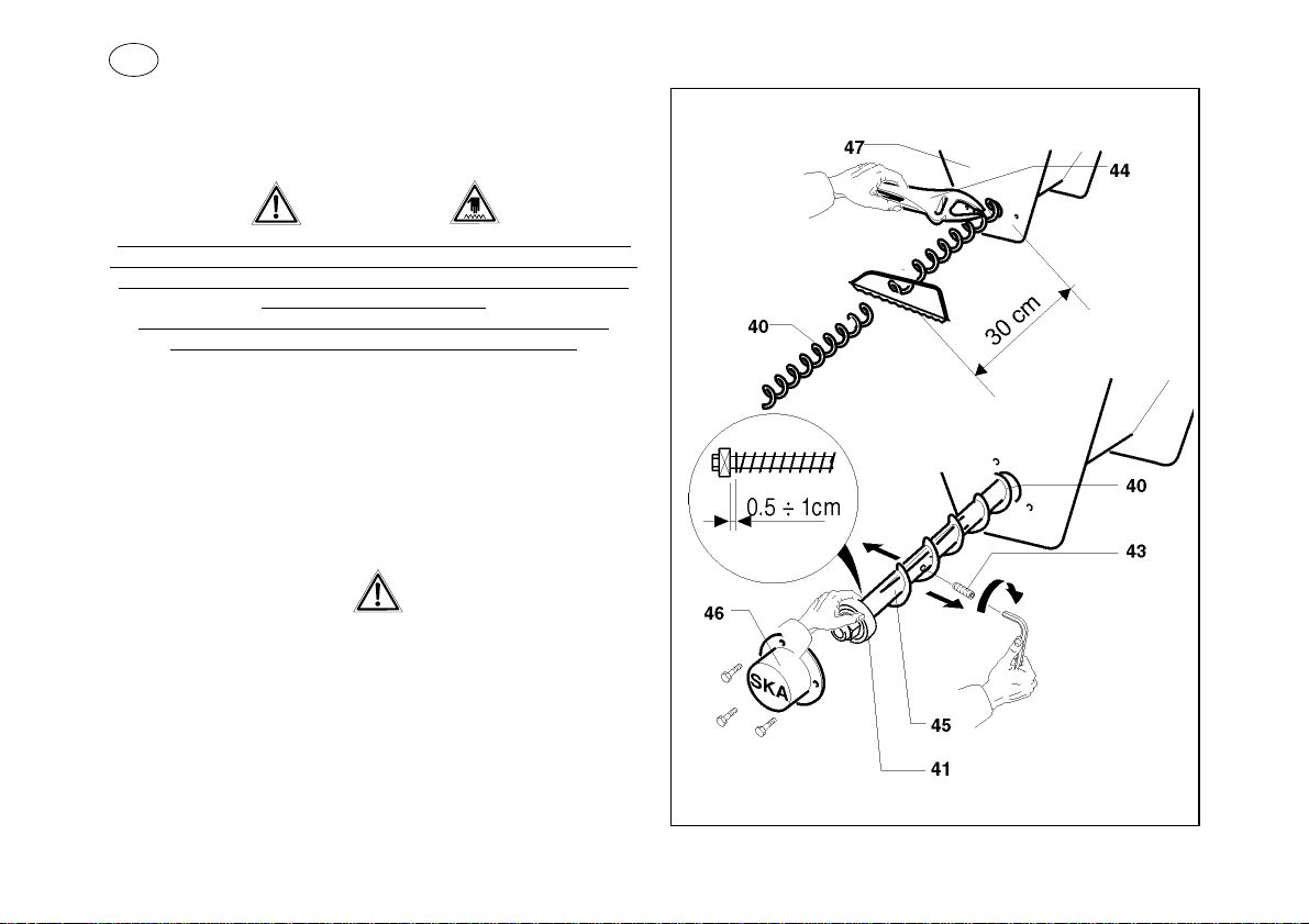
TENSIONE SPIRALE(fig. P)
La spirale (40) deve subire un pretiraggio in modo che questa si
assesti all’interno del tubo zincato.
L’operazione di mettere la spirale in tensione deve essere fatta da
personale qualificato, chiunque intervenga sulla spirale deve essere
conscio che eseguendo questa operazione ci si può ferire le mani
La spirale, se tesa, agisce come una molla, pertanto tende a
rientrare nel tubo trascinando le mani dell’operatore.
Mettere in tensione la spirale come segue:
•
la spirale (40) deve essere tesa per l’ 1% della lunghezza
dell’impianto e di ulteriori 30 cm circa, per l’inserimento
dell’alberino (45);
•
con una pinza a scatto (44) bloccarla a ridosso del pozzetto
(47);
tagliare la spirale a 30 cm dal pozzetto ed inserire, nella parte
•
eccedente, l’alberino (45) con cuscinetto (41);
LA SPIRALE NON DEVE TOCCARE IL CUSCINETTO (41),
ALTRIMENTI SI ROVINA! MANTENERE UNA DISTANZA DA
anche se la spirale non gira.
QUEST’ ULTIMO DI CIRCA 0.5÷1 CM.
•
dilatare l’alberino (45) con il grano (43) fino a bloccare completa
mente la spirale.
Togliere con molta attenzionela pinza a scatto, reinserire l’alberino
con la spirale nel pozzetto e fissare assieme alla protezione (46) con
viti.
SKA / 26
-
Fig. P
Page 27
GB
AUGER TENSION(ill. P)
The auger (40) must be pre-stretched in order to set it inside the
zinc-plated pipe.
F
TENSION DE LA SPIRALE(fig. P)
La spirale (40) doitsubir unprétirage de façonqu’elle puisses’ajuster
à l’intérieur du tube zingué.
The operation of stretching the auger must be done by qualified
personnel; the one who operates on the auger must be aware of the
risks that this operation includes.It is possible to injure the hands
The auger has the same behaviour as a spring i.e. it tends to go
back into the pipe, pulling with it the hand of the operator.
The auger can be stretched as follows :
•
the auger (40) must be stretched for a 1% of the installation
lenght and then of about 30 cm in order to insert the shaft (45);
block the auger close to the boot (47) with a release collet (44);
•
•
cut the auger at 30 cm from the boot and insert the shaft (45)in
the protruding end with bearing (41);
THE AUGER MUST NOT TOUCH THE BEARING (41),
THE GAP BETWEEN THEM MUST BE 0.5÷1 CM.
expand the shaft (45) with the dowel screw (43) to completely
•
block the auger.
By paving much caretakeoff the release collet, re-connect the shaft
withthe auger in the boot and fix togetherwith protection (46)by using
some screws.
even if the auger isn’t working.
OTHERWISE IT CAN BE DAMAGED!
L’operation de mettre en tension la spirale doit être fait de
personnel qualifié. Celui qui intervient sur la spirale doit être
conscient que, en exécutant cette opération, peut blesser ces
mains bien que la spirale ne tourne pas. La spirale, si tendue, agit
comme un ressort et tente de rentrer dans la tube entraînant les
Mettre en tension la spirale, comme suit:
la spirale doit être tendue pour l’1% de la longueur de
•
l’installation et encore pour 30 cm afin d’insérer l’arbre (45);
avec une pince à ressort (44) bloquer la spirale au-dessus du
•
boitard (47);
•
couper la spirale à 30cm du boitard et dans la partie en excès
faire passer la tige (45)avec roulement (41).
LA SPIRALE NE DOIT PAS TOUCHER LE COUSSINET (41),
GARDER UNE DISTANCE ENTRE LES DEUX D’ENVIRON 0.5÷1 CM.
dilater la tige (45) avec le grain (43) jusqu’à bloquer complète
•
ment la spirale.
Enlever avec beaucoup d’attentionla pince à ressort, réinsérer la tige
avec la spirale dans l’embasement et fixer la protection (46) avec des
vis .
mains de l’opérateur.
POUR NE LA DÉTÉRIORER PAS!
-
GAMMA / 27
Page 28
I
APPLICAZIONE ANTISOSTA:
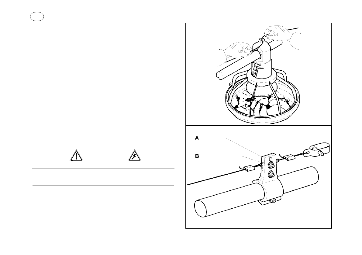
Il cavo antisosta viene applicato sulla parte superiore del tubo zincato
in modo da impedire agli animali di sostare sopra al tubo stesso,
eventualmente l’antisosta può essere elettrificato tramite un apposito
generatore di impulsi elettrici.
Infilateilcavoantisostasullasommitàdiciascuntubodiscaricofig. Q.
Per garantire una buona tensione dell’antisosta, applicare l’apposita
staffa di ancoraggio (A) con tenditore ogni 36 m c.a., vedi fig. R.
Utilizzate il foro inferiore (pos. B fig. R).
Utilizzare in prossimità della tramoggia e del gruppo traino le due
staffe isolate in acciaio (28) fig.B.
A conclusione di quanto precedentemente esposto, tutto èpronto per
funzionare.
AVVIAMENTO DELLA MANGIATOIA:
A questo punto non resta che ultimare i collegamenti tra il gruppo
traino, il microinterruttore di sicurezza, i pressostati ed il quadro
elettrico.
Fig. Q
Vi ricordiamo che i collegamenti eletrici devono essere eseguiti da
personale qualificato.
Fate molta attenzione al senso di rotazione della spirale : deve
corrispondere alla direzione di avanzamento del mangime verso il
gruppo traino .
SKA / 28
Fig. R
Page 29
GB
ANTIPERCH INSTALLATION:
Theantiperch wire is installed on the upper partof the galvanized pipe
to prevent animals stopping on the tube itself.The antiperch wire can
be fed by a special high tension generator.
Insert the wire onto the top of each drop tube, fig. Q.
To ensure good tension of the antiperch line, apply the anchor shatf
(A) with stretcher every 36 m., fig. R.
Use the lower hole (see position B fig. R)
Use the two insulated iron brackets (28), fig. B, respectively near the
hopper and the drive unit.
Onceeverything iscompleted as explainedabove, everythingisready
to be used.
F
INSTALLATION ANTIPERCHAGE:
L’antiperchageest appliqué sur la paroisupérieure du tube zingué, de
façon à empêcher que les animaux s’arrêtent sur le tube même;
eventuellement l’antiperchage peut être electrifié avec un generateur
d’impulsions électriques approprié.
Infiler le cable antiperchage sur la sommité de chaque tube de
descente, fig. Q.
Pour assurer une bonne tension de l’antiperchage, appliquer la tige
d’ancrage (A) avec tendeur chaque 36 mt. approx fig.R.
Utiliser le trou inférieur, (voir position B fig. R).
Utiliseren proximité de latrémie et du groupe d’entrainementles deux
étriers isolés en acier (28) fig.B
A la conclusion de ce qu’est exposé précédemment, tous est pret à
fonctionner.
STARTING OF THE SYSTEM:
At this point, the only thing left to do is to finish the connections
between the drive unit, the safety microswitch, the switch and the
electric panel.
Please remember that all electrical connections must be carried out
by qualified personnel.
Be careful of the sense of rotation of the auger: it must correspond
to direction in which the feed goes toward the drive unit !
DEMARRAGE DE LA MANGEOIRE:
A ce point il ne reste que terminer les jonctions de la groupe
d’entrainement, le microinterrupteur de securté, les palpeurs et le
tableau électrique.
Nous vous rappellons que les branchements électriques doivent
être faits des personnes qualifiées. Faire attention au sens de
rotation de la spiral: elle doit corrispondre à la direction d’aliment
vers le group d’entrainement !
GAMMA / 29
Page 30
I
Inserite la sfera di alluminio all’interno della tramoggia; quando la
spirale gira la sfera si muove mantenendo il mangime in agitazione, si
eviteranno così ristagni dentro la tramoggia.
Vi ricordiamo che nel gruppo traino esiste un microinterruttore che
viene azionato dal sollevamento dello sportellino, questo
microinterruttore deve essere collegato al quadro elettrico in modo
che quando si solleva lo sportellino il motore della spirale si arresta.
Se per qualche motivo il mangime arriva dentro il gruppo traino in
quantità rilevanti lo sportellino si solleverà arrestando la spirale.
Il microinterruttore ha inoltre la funzione di proteggere da accidentali
ferimenti.
E’ severamente vietato manomettere questo microinterruttore e tutti
i dispositivi che impediscono l’accesso con le mani dentro al gruppo
Chiunque manometta questi dispositivi con o senza l’ausilio di
attrezzi si rende responsabile degli incidenti che ne derivassero.
di traino.
SKA / 30
Page 31
GB
Insertthe aluminiumball inside thehopper; whenthe spiralrotates the
ball moves, keeping the feed moving. This avoids stagnation inside
the hopper.
F
Insérer la sphère d’alluminium à l’intérieure de la trémie; quand la
spiraltourne la sphèresedeplace en tenantl’alimenten agitation pour
éviter des stagnations dans la trémie.
Please note that there is a microswitch inside the drive unit which is
put into action when the door is raised. This microswitch must be
connected to the electric panel so that when the door is raised the
auger motor stops.
If, for some reason, feed enters the drive unit in relatively large
quantities the door will be raised, thus stopping the auger.
The microswitch also has the function of protecting from any
accidents.
It is prohibited to manhandle this microswitch and all the
components which block access of the hands inside the drive unit..
Whoever manhandles these components with or without the help of
equipment should be held responsable for any arising accidents.
Veuillez rappeller que dans le groupe d’entrainement il y a un
microinterrupteur qu’est actionné du soulevement du guichet, ce
microinterrupteur doit être joint au cadre électrique pour faire que
quand on soulève le guichet, le moteur de la spiral s’arrete.
Si pour quelque raison l’aliment arrive dans le groupe d’entrainement
en quantité rélévante, le guichet se leve en arretant la spiral.
Le microinterrupteur a ,en plus, la fonction de proteger des blessures
accidentelles!
Il est interdit severement de modifier ce microinterrupteur et tous les
dispositifs qu’empechent l’acces avec les mains dans le groupe
d’entrainement.
Ce qui manomette ces dispositifs sans l’aide d’équipement se rent
responsable des incidents qui arrivent.
GAMMA / 31
Page 32
I
SALDATURA SPIRALE:
Sela spirale avesse bisogno di essere allungata o per qualche motivo
si fosse rotta, può essere saldata, vedi fig. S.
L’operazione deve essere fatta da personale qualificato, una errata
saldatura può danneggiare la tubazione e compromettere il
funzionamento dell’impianto.
Per la saldatura usare un elettrodo universale basico diametro 2.5
mm.
A saldatura ultimata il cordone di saldatura non deve sporgere
verso l’esterno altrimenti lo sfregamento finirebbe per danneggiare il
tubo.
La spirale deve essere raffreddata all’aria: un raffreddamento rapido
causerà un indurimento ed una fragilità che può portare ad una facile
rottura.
Per prevenire surriscaldamento e curvature, per mantenere la spirale
diritta, evitare attorcigliamenti, porla in un angolare o tubo in ferro e
tenerla ben rigida.
Non devono mai essere saldate tra di loro spirali che non siano
perfettamente uguali.
Anche pochi millimetri di differenza possono creare danni ai tubi,
oppure intasare il trasportatore.
SKA / 32
Fig. S
Page 33
GB
WELDING OF THE AUGER:
Should the auger need to be lengthened or should it be broken, it can
be welded, see fig. S.
F
SOUDAGE DE LA SPIRAL:
Si la spiral a besoin d’être prolongée, ou si pour quelque raison elle a
été cassée, elle peut être soudée, voir dessin S.
The operation must be done by qualified staff; bad welding could
cause damages to the pipes and alterate the working of the system.
Fortheweldinguseanalkalineuniversalelectrodediametre2.5mm.
Once finished welding, it should not be rough because it will
damage the tube if it rubs.
The auger must be air-cooled : quick cooling might cause hardening
and brittleness, easily allowing breakage.
To prevent overheating and bendingof the auger, keep itstraight and
toavoid bending andtwisting, place it inan angle or inan iron tube and
keep it stiff.
Augers which are not perfectly equal should never be welded
together.
Even a few millimeters can damage the tube, or block the feed
conveyor.
Une personne qualifiée doit faire cet opération, une soudure erronée
peut endomager les tubes et compromettre le fonctionnement de
l’installation.
Pour la soudure utiliser un electrode universal alcalin, diametre 2.5
mm.
A termination soudure le cordon de soudure ne doit pas saillir, vers
l’exterieure, sinon le frottement terminera pour endomager le tube.
La spiral doit être refroidi à l’aire: un refroidissement rapide causera
undurcissementetunfragilitéquepeuventporteràunrupturefacile.
Pour éviter surchauffage et courbes, pour maintenir la spiral droite, et
pour éviter entortillements, il faut la placer dans une cornière ou dans
un tube de fer et la tenir bien tendue.
Nous ne devez jamais souder ensemble des spirals que ne sont
pas parfaitement égals.
Peu de millimètres de difference peuvent dommager les tubes, ou
bloquer le transporteur.
GAMMA / 33
Page 34
I
MANUTENZIONE:
La manutenzione viene fatta settimanalmente.
Pochi minuti spesi per la manutenzione o più semplicemente per un
controllo fanno risparmiare tempo, denaro e allungano la vita del
Vostro impianto.
Controllare il pressostato posto nella tramoggia, deve essere pu
•
lito da incrostazioni e da ristagni di mangime.
Controllare il cuscinetto posto nel pozzetto (deve ruotare libera
•
mente)
Controllare l’allineamento della tubazione.
•
Controllare il pressostato dell’ultimo piatto.
•
Controllare il buon funzionamento del microinterruttore posto sul
•
gruppo di traino.
Controllare il buon funzionamento della centralina antisosta (at
•
tenzione alle dispersioni di corrente che rendono inefficace la
centralina ).
Ingrassare con regolarità i cuscinetti, gli ingranaggi dei verricelli
•
e i tratti di fune che si avvolgono sui tamburi.
•
Controllare il serraggio dei bulloni.
Controllare lo stato delle funi di sollevamento.
•
•
Verificare il buono stato dell’impianto elettrico.
Non lasciare mai per nessun motivo del mangime fermo dentro la
tubazione per lungo tempo; se tale mangime assorbe umidità
oppure fermenta può causare anche il blocco della spirale.
Non lasciare entrare nell’impianto bulloni, chiodi, utensili, topi
etc.Corpi estranei come questi possono causare gravi danni alla
spirale.
-
-
-
Per evitare ciò vi consigliamo di acquistare la rete di protezione da
porre sulla tramoggia art.45753000 oppure il coperchio di
protezione art.45752000.
SKA / 34
Page 35
GB
MAINTENANCE:
Maintenance must be done weekly.
A few minutes spent doing maintenance or a check-up means time
and money saved, and also lengthens the life of your system.
Check the microswitch inside the hopper, it must be clear from
•
cake and from retention of feed.
•
Check the bearing in the boot (it must run free without too much
friction).
Check the level of the line.
•
•
Check the microswitch on the last pan.
Check the security limit switch on the drive unit.
•
Check the shocker wire ( be careful of loss of current which ma
•
kes the device unusable).
Grease periodically the bearings, the gears of the winches and
•
the parts of the cable which are wrapped onto the rolls.
•
Check the fixing of the nuts.
Check the condition of the lifting ropes.
•
Check the good condition of electric system
•
F
MANUTENTION :
La manutention doit être fait chaque semaine.
Peude minutes utilisés pour la manutention ouplus semplement pour
uncontrol font un gain de temps, d’argent etl’allongement de la vie de
votre installation.
Contrôler le palpeur mis dans la trémie, il doit être net des incro
•
stations et des stagnations d’aliment.
Contrôler le palier dans le boitard (il doit se tourner librement).
•
Contrôler l’alignement des tubes.
•
•
Contrôler le palpeur de la dernière assiette.
Contrôler le bon fonctionnement du microinterrupteur mis sur le
•
-
groupe d’entrainement.
•
Contrôler le bon fonctionnement du tableau antiperchage (atten
tion aux dispersions de courant qui rendent inefficace le ta
bleau).
•
Grasser regulièrement les paliers, les engrenages des treuils, et
les pièces de cable qui se tournent sur les tambours.
Contrôler le serrage des boulons.
•
Contrôler l’état des câbles de levage.
•
Contrôler le bon état de l’installation électrique
•
-
-
-
Never leave feed for long periods inside the pipe for any reason
without moving it; if the feed absorbs moisture or ferments, it can
cause a blockage of the auger.
Never leave bolts, nuts, nails, rivets, tools, mice, etc. inside the
system.Foreign bodies or objects like the above could seriously
damage the auger and the pipe.
To avoid this we suggest buying the protection mesh item
45753000 to be put on the hopper or the protection cover item
45752000.
Ne laisser jamais pour aucun motif de l’aliment dans les tubes pour
beaucoup de temps; si cet aliment absorbe humidité ou fermente il
peut causer un blocage de la spiral.
Ne laisser pas entrer dans l’installation des boulons, clous, outils,
souris etc. Les corps étrangers comme ceux-la peuvent causer des
domages graves à la spiral.
Pour éviter ça nous vous conseillons de commander le filet de
protection à mettre sur la trémie
art. 45753000, sinon le couvercle de protection art. 45752000.
GAMMA / 35
Page 36
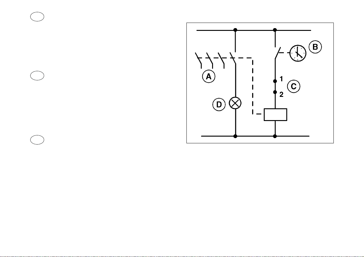
I
SCHEMA ELETTRICO PER IL COMANDO
DEI MOTORI
K Contattore di potenza per comando motore
H Luce spia
S1 Finecorsa mangiatoie
S2 Finecorsa sicurezza gruppo traino
GB
WIRING DIAGRAM FOR MOTORS
CONTROL
K power contactor for motors control
H Warning light
S1 Feeder end switch
S2 Safety end switch for drive unit
F
SCHÉMA ELÉCTRIQUE POUR LE
CONTRÔLE DES MOTEURS
K Contacteur de puissance pour contrôle moteurs
H Lampe témoin
S1 Fincourse mangeoir
S2 Fincourse de sécurité pour le groupe de entraînement
SKA / 36
 Loading...