

SJE Rhombus VS21-7.0-N3RD, VS21-10.0-N3RD, VS23-16.5-N3RD, VS23-31.8-N3RD, VS23-45.0-N3RD User Manual
...Page 1
VARIOspeed®3R Duplex
User Manual
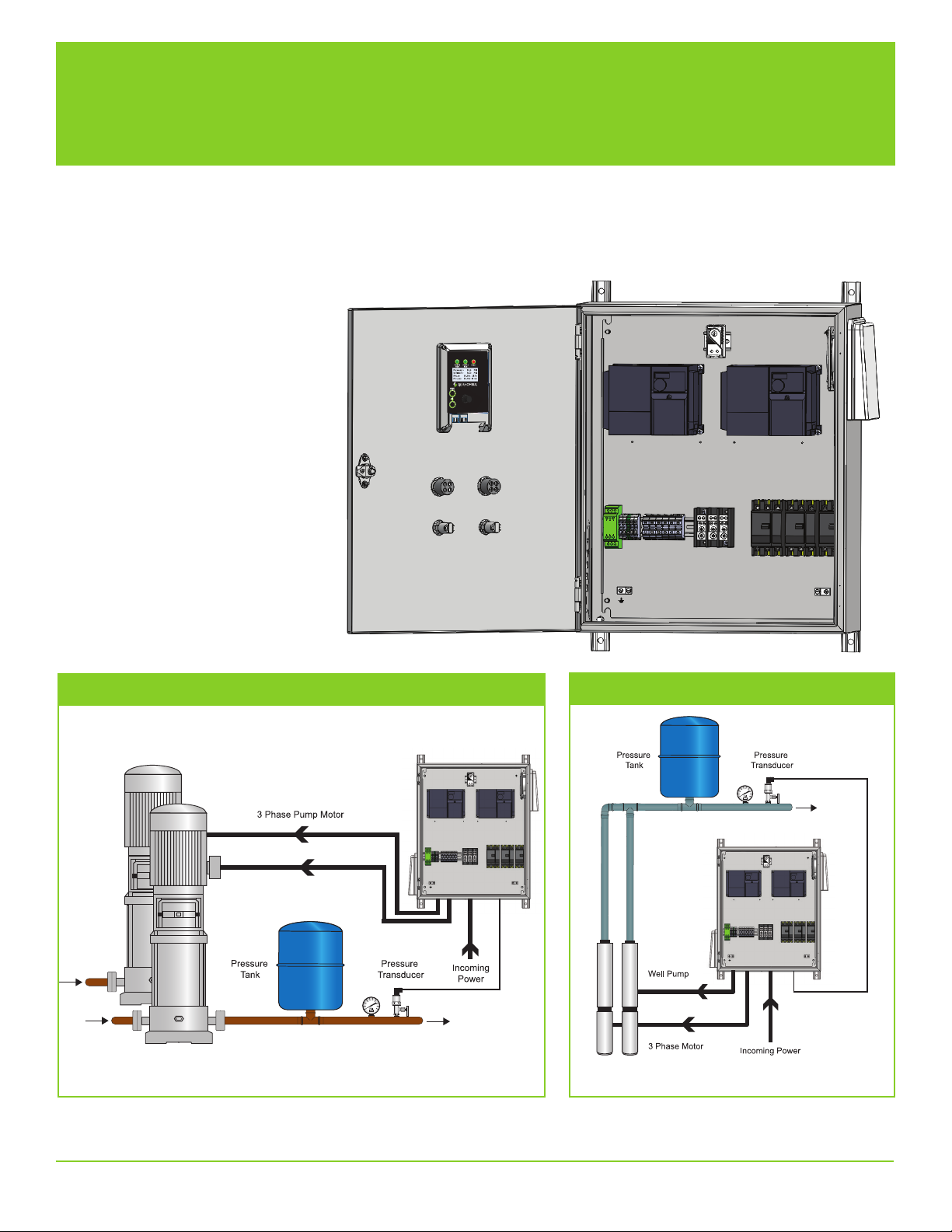
This VARIOspeed® 3R Duplex control panel is designed to provide constant pressure control for your pumping system.
Should you need to make minor adjustments, please consult the parameter table enclosed in this document.
Consult the factory for assistance.
Pressure Booster Pump Application
Deep Well Submersible Pump Application
VARIOspeed® 3R Duplex User Manual 1
Page 2
WARNINGS
Failure to read and understand the information provided in this manual may result in personal injury
or death, damage to the product or product failure. Please read each section in its entirety and be
sure you understand the information provided in the section and related sections before attempting
any of the procedures or operations given.
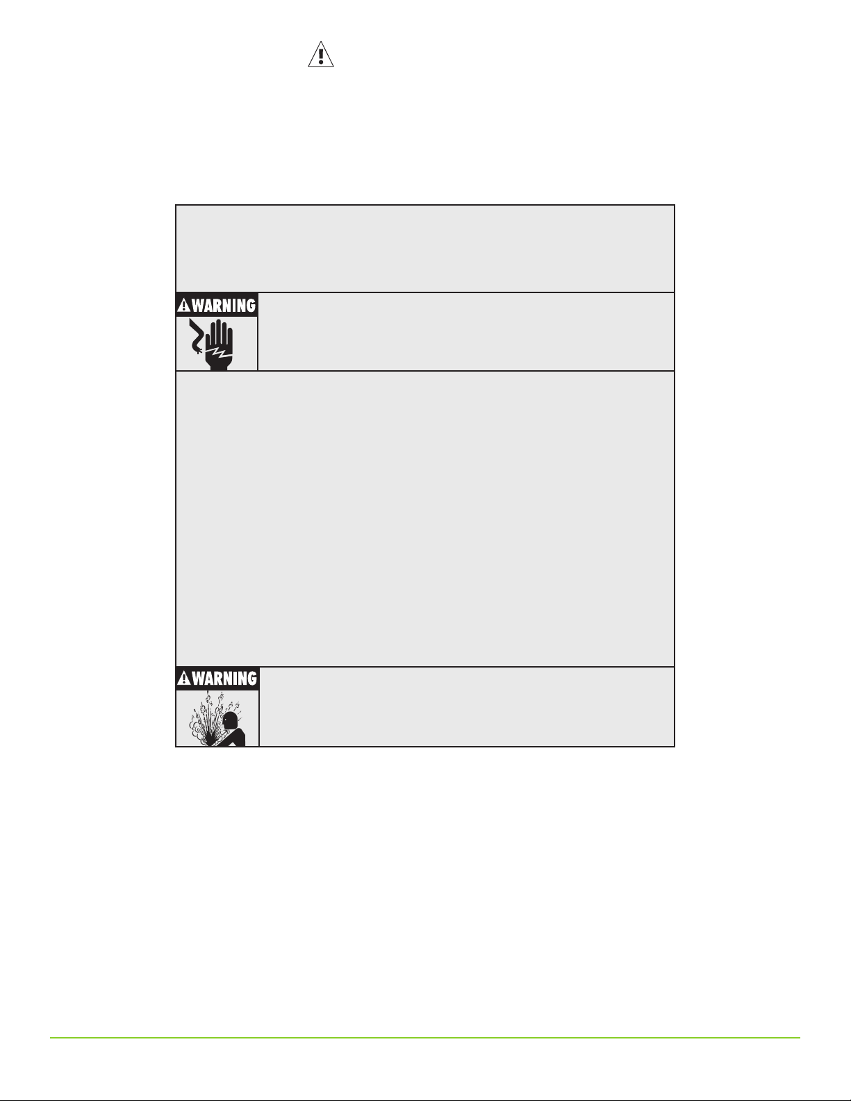
Failure to follow these precautions could result in serious injury or death. Keep these
instructions with warranty after installation. This product must be installed in accordance with National Electrical Code, ANSI/NFPA 70 so as to prevent moisture from
entering or accumulating within the controller housing.
See additional specifications on page 3 of this manual.
ELECTRICAL SHOCK HAZARD
Disconnect power to the VARIOspeed® 3R Duplex Panel and wait 10
minutes before removing the VFD covers.
A qualified service person must install and service this product according
to applicable codes and electrical schematics.
• Lethal voltages are still present inside the VARIOspeed® 3R Duplex Panel after power
is disconnected. Wait 10 minutes to allow internal capacitors to fully discharge before
attempting to connect or disconnect wire or to service this equipment.
• Do not connect incoming power to motor terminals U, V, W. Doing so will result in
irreversible damage to the drive.
• Do not connect power to this equipment if it has been damaged or has any missing parts.
• Verify that the incoming voltage supply matches the VFD rating before applying power to the
unit.
• The VARIOspeed® 3R Duplex VFD’s contain no serviceable parts, do not attempt to repair
this equipment.
• The VARIOspeed® 3R Duplex Panel must be grounded at the grounding terminal according
to N.E.C. Refer to the electrical connection on page 12.
• Do not install in areas with: excessive or conductive dust, corrosive or flammable gas,
excessive heat, regular impact shocks or excessive vibration.
• Do into install in areas where ambient temperature exceeds 40ºC (104ºF).
EXPLOSION OR FIRE HAZARD
Do not use this product with flammable liquids. Do not install in
hazardous locations as defined by National Electrical Code,
ANSI/NFPA 70.
2 VARIOspeed® 3R Duplex User Manual
Page 3
Specification/Selection
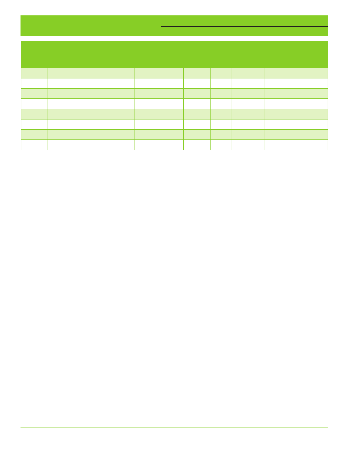
PART
NUMBER DESCRIPTION MODEL
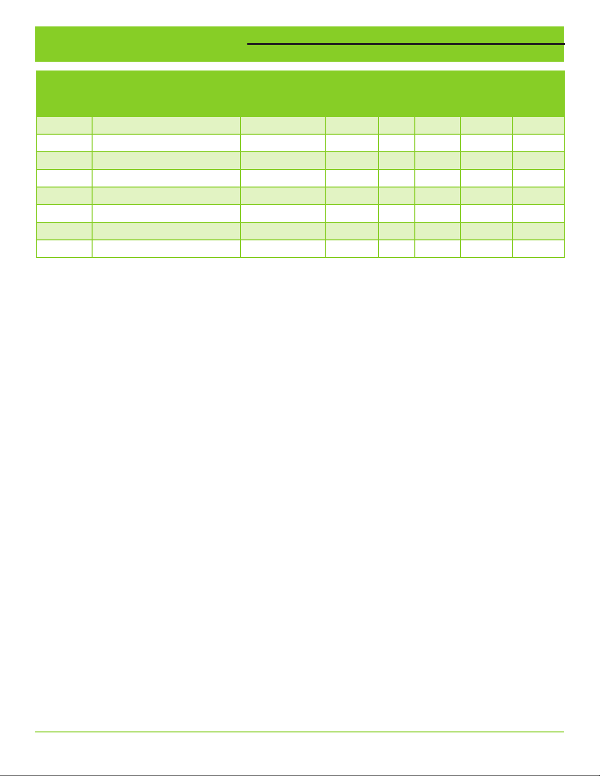
1051672 VARIOspeed® 3R Duplex, 240V VS21-7.0-N3RD 7.0 1.5 1 3 115 lbs.
1051673 VARIOspeed® 3R Duplex, 240V VS21-10.0-N3RD 10.0 3 1 3 115 lbs.
1051674 VARIOspeed® 3R Duplex, 240V VS23-16.5-N3RD 16.5 5 3 3 115 lbs.
1051675 VARIOspeed® 3R Duplex, 240V VS23-31.8-N3RD 31.8 7.5-10 3 3 146 lbs.
1051676 VARIOspeed® 3R Duplex, 240V VS23-45.0-N3RD 45.0 15 3 3 154 lbs.
1051677 VARIOspeed® 3R Duplex, 240V VS23-58.0-N3RD 58.0 20 3 3 154 lbs.
1051678 VARIOspeed® 3R Duplex, 480V VS43-16.0-N3RD 16.0 7.5-10 3 3 150 lbs.
1051679 VARIOspeed® 3R Duplex, 480V VS43-29.5-N3RD 29.5 15-20 3 3 161 lbs.
Note: HP rating is based on standard NEMA B 4-pole motor (used for indication only, use nameplate FLA for sizing). The
output voltage of the VFD cannot exceed the incoming voltage. Example: 208V in, 208V out (max).
Selecting the Correct VFD
1. Determine the voltage available on site.
2. Select pumps with the same voltage (motor must be 3 phase).
3. Check pump motor nameplate Full Load Amps (FLA) for proper VFD sizing.
4. Select a VFD with an output amp rating higher than motor FLA.
5. Use motor Service Factor Amps (SFA) for submersible well pump applications for VFD sizing.
Phase Conversion
It is possible to supply single phase 240V input power to VS23 models. The VFD output amp must be derated by 50%.
Example: The VS23-45.0-N3RD will be derated to 22.5A output (max).
*Use three-phase input power if available. VS23 VFD’s are not UL listed with single-phase supply. Always use a 3 phase motor.
OUTPUT
AMPS HP
INPUT
PHASE
OUTPUT
PHASE
SHIP
WEIGHT
Maximum Motor Cable Lengths
For 208V-240V pumps: 400 ft. For cable lengths greater than 400 ft., use a load reactor for each pump. Do not exceed
800 ft.
For 480V pumps: 50 ft. For cable lengths greater than 50 ft., use a load reactor for each pump. Do not exceed 300 ft.
Environmental
Operating temperature: 14ºF to 104ºF (-10ºC to 40ºC)
Storage temperature: -4ºF to 131ºF (-20ºC to 55ºC)
Altitude: Maximum of 3280 ft (1000m) above sea level
VARIOspeed® 3R Duplex User Manual 3
Page 4
Display Features and Navigation
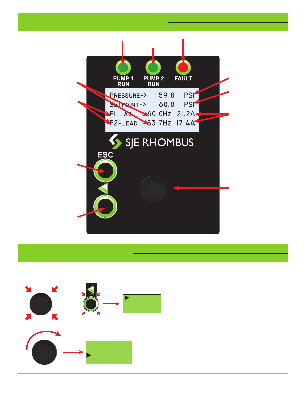
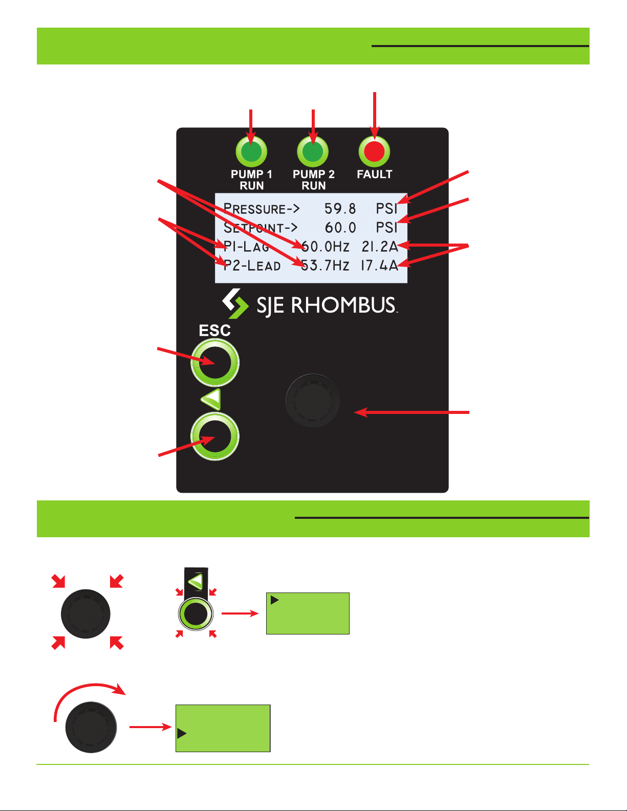
PUMP 1 and PUMP 2
Output Frequency
PUMP 1 and PUMP 2
Lead/Lag Status
Escape Button:
Used to exit without
saving setting values
or to return to the
main monitor screen.
PUMP 1
Run Indicator
Fault Indicator
PUMP 2
Run Indicator
Current Pressure
Set Point Pressure
PUMP 1 and PUMP 2
Motor Current
Left Button:
Used for digit
selection during
editing.
Programming Examples
Changing the Pump 1 Motor Overload Amps
1. From the main display, press the Left or Enter button to enter the settings menu.
Set Pressure
OR
2. Rotate the rotary selector until the selection arrow highlights “Set Pump 1 Motor OL Amps”.
Set Start Di Press
Set Lag Start Di
Set Lag Stop Di
Rotary\Push Knob:
Used to scroll through
the menu and edit
setting values
Set Lag Stop Di
Set Lag Stop Time
Set Alternation Time
Set Pump 1 OL Amps
4 VARIOspeed® 3R Duplex User Manual
Page 5
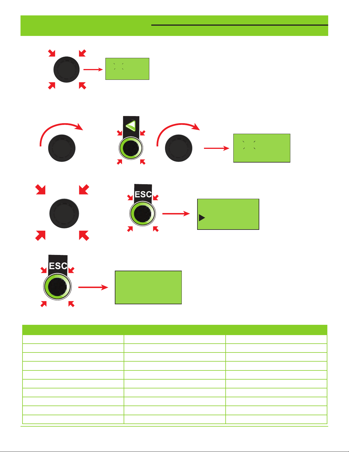
Programming Examples
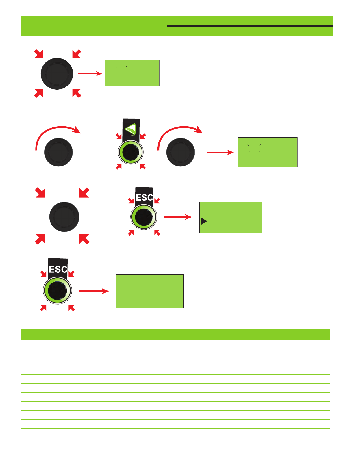
3. Press the rotary selector to enter Pump 1 Current editing.
Set Pump 1 Current
12.3 Amps
(Use nameplate data)
Min 0 Max 60
4. Rotate the selector to begin editing the value. Pressing the left arrow button will move the editing position left one
digit. This is useful when making large adjustments to the edited value quickly.
Set Pump 1 Current
OR
5. Press the rotary selector to save the edited value and exit the editing screen. Or press the ESC button (escape) to
exit the editing screen without saving.
+
13.3 Amps
(Use nameplate data)
Min 0 Max 60
Set Lag Stop Di
OR
Set Lag Stop Time
Set Alternation Time
Set Pump 1 OL Amps
5. If no further setting needs to be edited, press the ESC button to return to the main display.
SETUP PARAMETER + LOG MENU
Set Pressure Set Pump 2 Voltage Set 1st Decel Time
Set Start Diff Pres Set Sleep Frequency Set Accel 2 Sw Freq
Set Lag Start Diff Set Sleep Time Set Acc/Dec Time
Set Lag Stop Diff Set Xducer Max Range Set High Press Alarm
Set Lag Stop Time Set Min Frequency Set Run Dry Press
Set Alternation time Set Max Frequency Set Run Dry Restart
Set Pump 1 OL Amps Set PID Prop Term View Run Times
Set Pump 1 Voltage Set PID Integ Term View VFD1 Fault Hist
Set Pump 2 OL Amps Set 1st Accel Time View VFD2 Fault Hist
View Error Log
VARIOspeed® 3R Duplex User Manual 5
Page 6
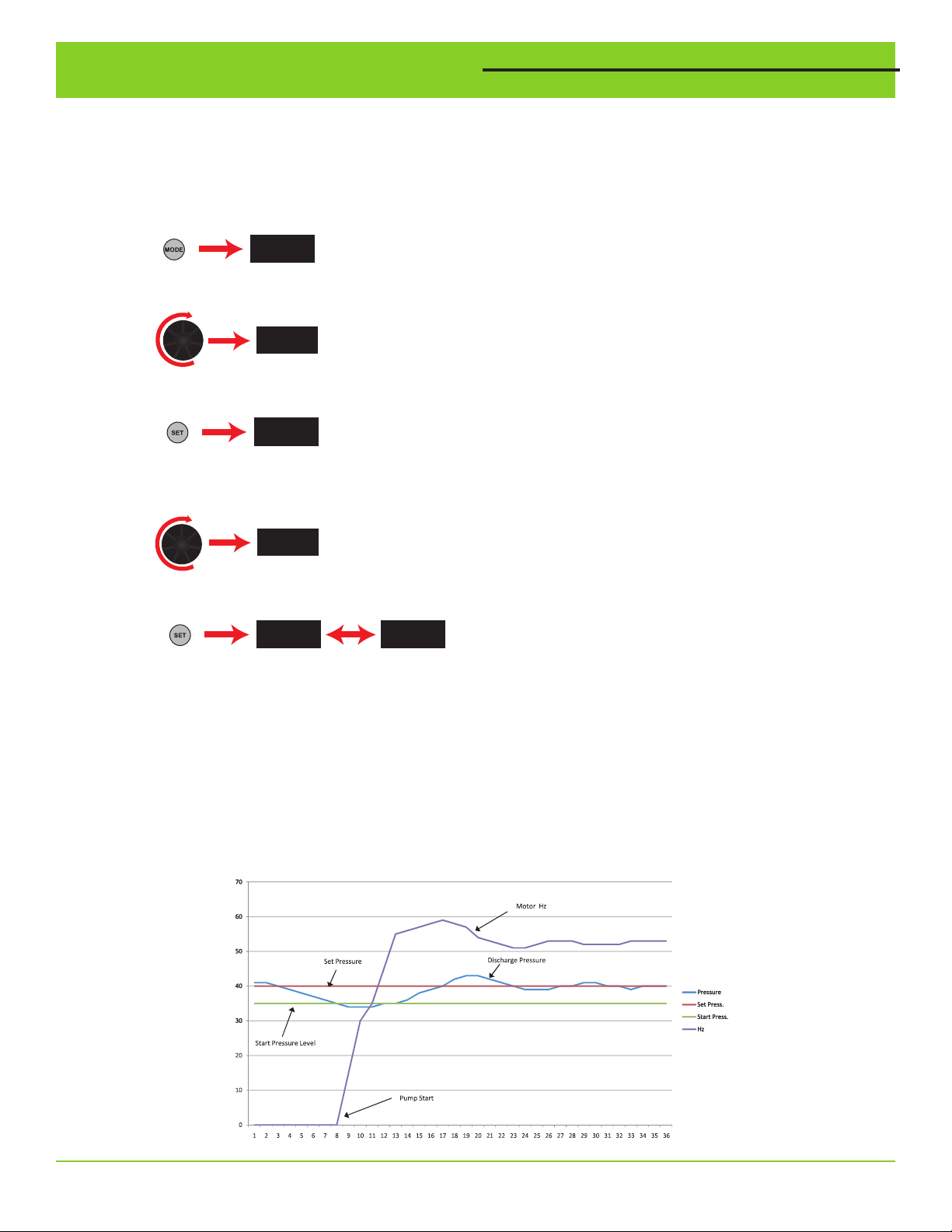
HAND/OFF/AUTO Operation
P. 000
P. 004
P. 000
P. 004
P. 000
60.00
55.00
55.00
P. 004
P. 000
P. 004
P. 000
60.00
HAND position
The pump will run at a fixed speed. The HAND mode frequency can be set in the VFD by entering a value in P.4.
NOTE: In HAND mode, the system pressure is not monitored so the system must be supervised at all times while being
used.
Changing the HAND Speed Reference (changes made on each VFD)
1. On the VFD, press MODE to choose the parameter setting mode.
(The parameter number read
previously appears.)
2. Turn the SETTING DIAL until P.4 appears.
P. 004
3. Press SET to read the current hand speed value. “60.00” (initial
value) appears.
60.00
4. Turn the SETTING DIAL to change it to the new hand speed value
“55.00”.
55.00
5. Press SET to save. Flash --- Parameter setting complete!
• Press MODE twice to return the monitor to frequency monitor.
OFF position
The pump will not run.
AUTO position
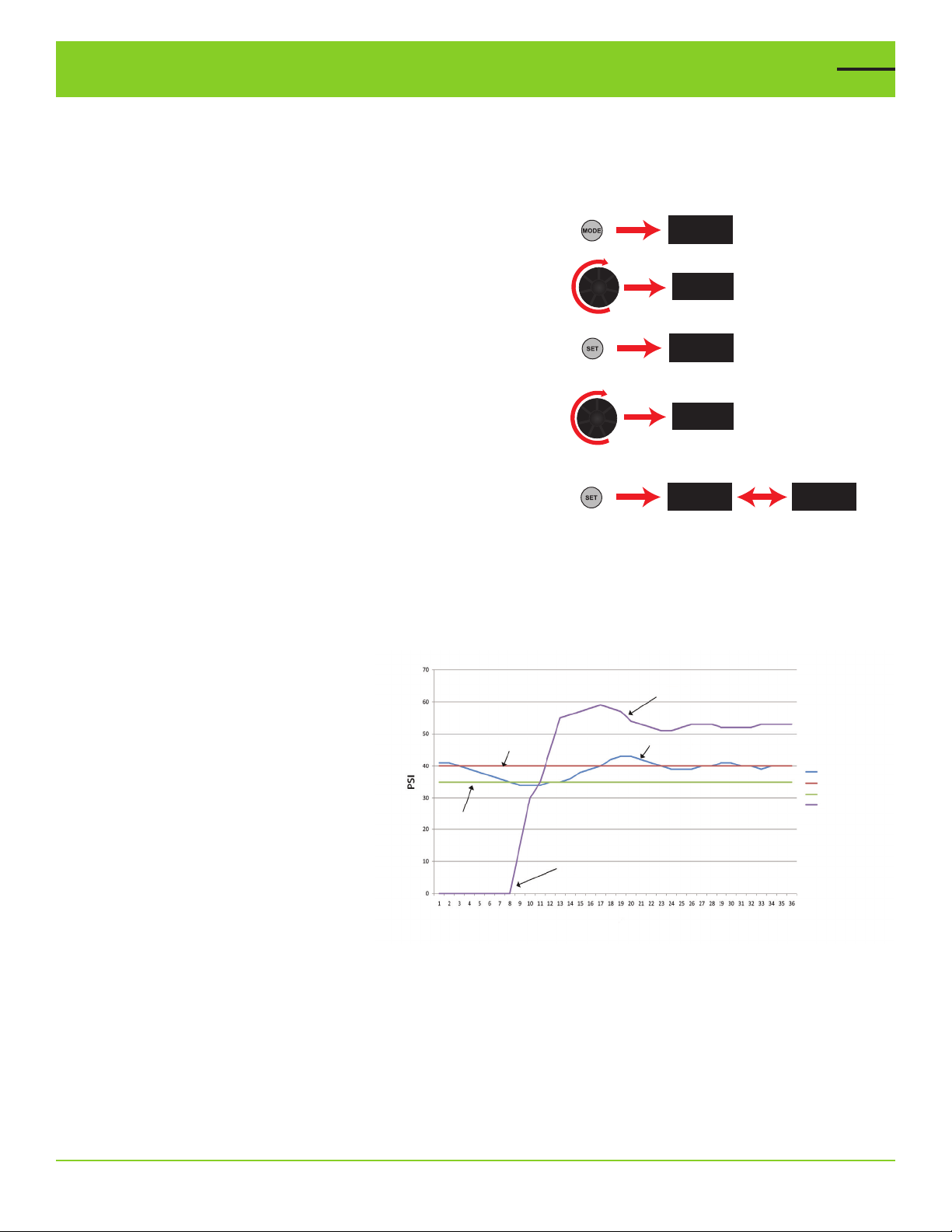
The lead pump will not run if the pressure is above the Set Pressure. The lead pump will start automatically if the
pressure drops below the Set Pressure less the Start Diff. Press. Example: If the Set Pressure is 40 PSI, and the Start
Diff. Pressure is 5 PSI. The lead pump will start when the pressure drops below 35 PSI (see example below). The lag
pump will start when the lead pump is running at full speed and the pressure is below the Set Pressure less the Lag
Start Differential for five seconds. The lag pump will run at full speed while in operation. The lag pump will stop when
the pressure exceeds the Set Pressure plus the Lag Stop Differential for the Lag Stop Time.
6 VARIOspeed
PSI
Sec.
®
3R Duplex User Manual
Page 7
Pressure Transducer Fail Shutdown
In the event that the pressure transducer signal should be lost, the system will shut the pump(s) off. During the
transducer fail error, the display will flash “SENSOR FAILURE” on the main display and the fault indicator will illuminate.
If the transducer failure is corrected, the display will return to its normal condition and normal pressure control will
resume.
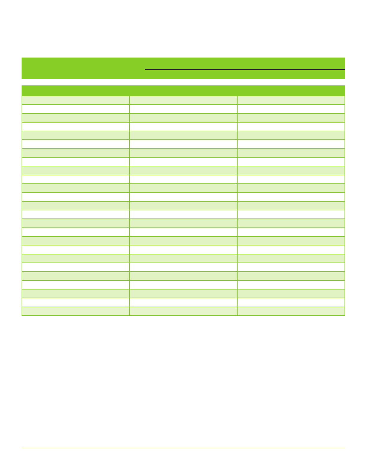
Parameter Setup List
SETTING DESCRIPTION RANGE DEFAULT
Set Pressure 0 to “Xducer Max Range” -0.1 60.0 PSI
Start Diff Pressure 0 to “Set Pressure” -1 5 PSI
Lag Start Diff Pressure 0 to “Set Pressure” -1 7.0 PSI
Lag Stop Diff Pressure 0 to “Xducer Max Rng” - “Set Pressure” 5.0 PSI
Lag Stop Delay Time 0 to 999 seconds 2.0 seconds
Alternation Time 1 to 168 hours 24 hours
Pump 1 OL Amps 0 to VFD Amp Rating Model Specific
Pump 1 Voltage 0 to 1000 Volts Model Specific (240/480)
Pump 2 OL Amps 0 to VFD Amp Rating Model Specific
Pump 2 Voltage 0 to 1000 Volts Model Specific (240/480)
Sleep Frequency 0 to “Max Frequency” 35.0 Hz
Sleep Time 0 to 3600 seconds 10 seconds
Xducer Max Range 0 to 1000 PSI 200 PSI
Min Frequency 0 to “Max Frequency” 30.0 Hz
Max Frequency “Min Frequency” to 120 Hz 60.0 HZ
PID Proportional Term 0.1 to 1000% 100.0%
PID Integral Term 0.1 to 3600 seconds 1.0 seconds
1st Accel Time 0 to 3600 seconds 2 seconds
1st Decel Time 0 to 3600 seconds 2 seconds
Accel 2 Switchover Freq 0 to “Max Frequency” 30 Hz
Accel/Decel Time 0 to 3600 seconds 3 seconds
High Pressure Alarm 0 to “Xducer Max Range” - 0.1 90.0 PSI
Run Dry Pressure 0 to “Set Pressure” -1 15 PSI
Run Dry Delay Time 0 to 6.0 minutes 0.5 minutes
Run Dry Restart Time 0 to 999.9 minutes 0.0 minutes (manual restart)
Set Pressure
Set Pressure is the target pressure to be maintained at the pump discharge. It cannot exceed the maximum range of
the pressure transducer.
Start Diff Pressure
The Start Diff. Pressure is the amount of pressure drop from the Set Pressure, at which the lead VFD will wake from
sleep and run to maintain the system pressure. The lead pump will start if the pressure drops below the Set Pressure
less the Start Diff. Pressure. Example: If the Set Pressure is 40 PSI and the Start Diff. Pressure is 5 PSI, the lead
pump will start when the pressure drops below 35 PSI.
Lag Start Diff Pressure
The Lag Start Diff. Pressure is the amount of pressure drop from Set Pressure, while the lead VFD is running full
speed and five seconds has passed, before the lag VFD is started. The lag VFD is run at full speed while in operation.
The lead VFD will not be allowed to enter sleep mode while the lag VFD is running.
Lag Stop Diff Pressure
The Lag Stop Diff. Pressure is the amount of pressure over the Set Pressure, after the Lag Stop Time has passed,
before the lag VFD is stopped.
VARIOspeed® 3R Duplex User Manual 7
Page 8
Parameter Setup List
Alternation Time
The Alternation Time is the total accumulated run time of the current lead VFD, before the lead operation is passed to
the other VFD. Alternation Time is intended to even out the wear of the VFD’s by transferring the lead operation after
a set period of run time.
Pump 1/Pump 2 OL Amps
The VFD’s electronic overload will signal an overload fault and protect the motor from damage in the event of an
overload condition. Set the Pump1/Pump 2 Motor OL Amps setting to the motor nameplate Full Load Amps for nonsubmersible pumps and to the Motor Max Amps for submersible pumps.
Pump 1/Pump 2 Voltage
Set the Pump 1/Pump 2 Motor Voltage setting to the voltage rating found on the motor nameplate. This value must
not exceed the voltage of the incoming power.
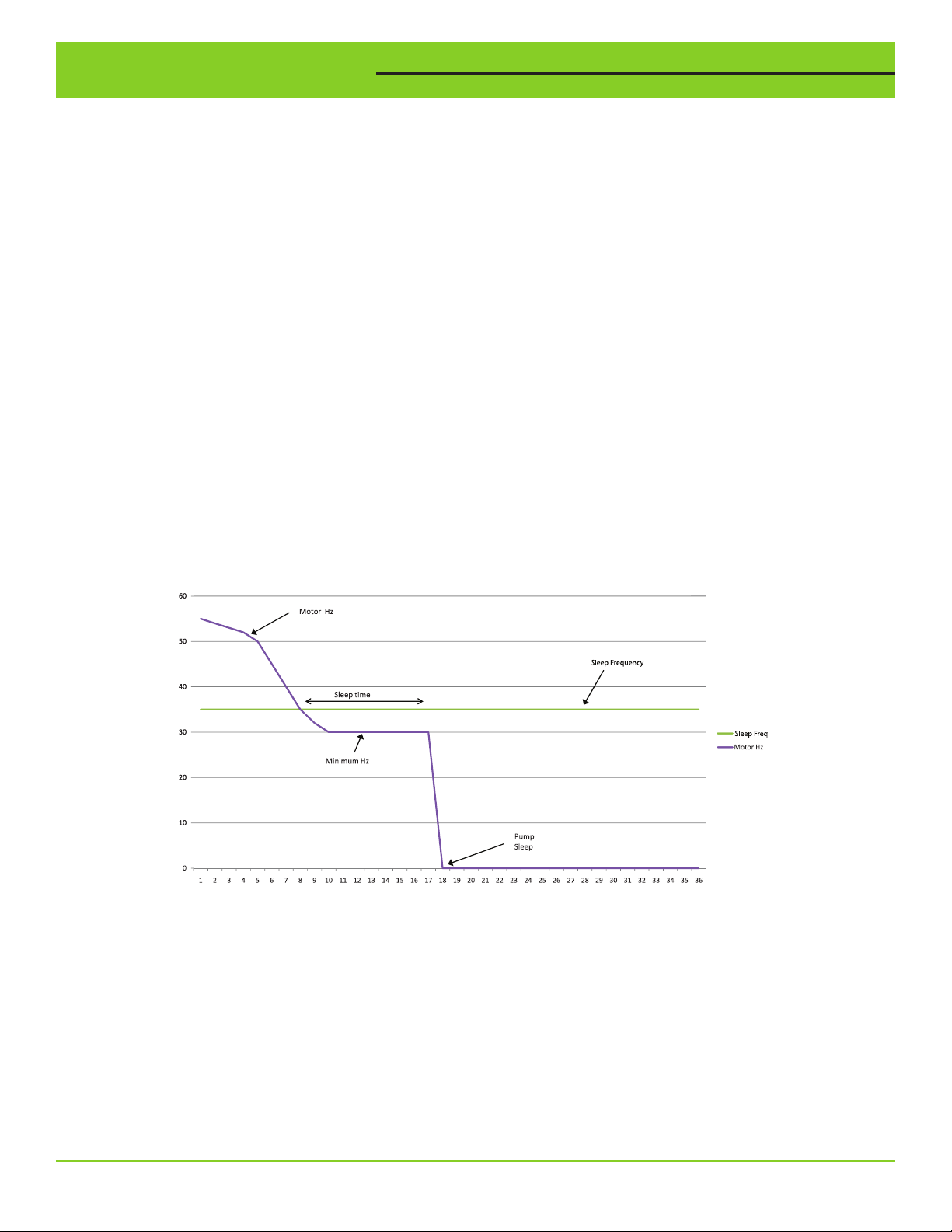
Sleep Frequency
Set the Sleep Frequency to the frequency at which the lead pump no longer builds pressure when operating at or near
the Set Pressure. The lead VFD will enter the “sleep” mode when the output frequency of the lead VFD drops below
the Sleep Frequency for a period of time (Sleep Time). The sleep function is temporarily suspended while the lag VFD is
in operation.
Sleep Time
Set the Sleep Time to the amount of time that the lead VFD will wait before entering “Sleep” mode after the output
frequency drops below the Sleep Frequency. Note: If the system cycles on and off too frequently, try the following:
increase the Sleep Time, lower the Sleep Frequency, or increase the Start Pressure. A combination of changes of all
three settings may be necessary. If the lead VFD does not enter “Sleep” mode when there is no flow of water in the
system, the Sleep Frequency must be increased.
Hz
Sec.
Sleep Function
Xducer Max Range
If using a different transducer other than supplied, set the Xducer Max Range to the full span rating of the pressure
transducer. The Set Pressure and Start Diff. Pressure values must also be updated after changing the Xducer Max
Range, as these values are automatically scaled based on the Xducer Max Range.
Min Frequency
The Min Frequency should be set to the minimum output frequency that the pumps should be allowed to run. Contact
your pump manufacturer to obtain the pump safe operation ranges.
8 VARIOspeed® 3R Duplex User Manual
Page 9

Parameter Setup List
Max Frequency
The Max Frequency should be set to the maximum output frequency that the pumps should be allowed to run. Contact
your pump and motor manufacturer for operation above 60 Hz.
PID Proportional Term
The PID Proportional Term is intended to be adjusted by advanced users only. The PID Proportional Term is used to
adjust the reaction of the output frequency to changes in the system pressure. Decreasing the PID Proportional Term
will allow the lead VFD to make larger corrections to the output frequency with differences between the Set Pressure
and actual system pressure. Increasing the PID Proportional Term will allow the lead VFD to make smaller corrections
to the output frequency with differences between the Set Pressure and actual system pressure.
PID Integral Term
The PID Integral Term is intended to be adjusted by advanced users only. The PID Integral Term is used to adjust how
quickly the output frequency reacts to changes in the system pressure. Decreasing the PID Integral Term will allow
the lead VFD to make quicker corrections to the output frequency with differences between the Set Pressure and
actual system pressure. Increasing the PID Integral Term will allow the lead VFD to make slower corrections to the
output frequency with differences between the Set Pressure and actual system pressure.
1st Accel Time
Set the 1st Accel Time to the rate at which the output frequency will accelerate from 0 Hz to the Accel 2 Switchover
Frequency. This time is based on the time the VFDs would take to accelerate from 0 Hz to 60 Hz. Example: If the
pump is required to accelerate from stop to 30 Hz in 1 second the 1st Accel Time should be set to 2 seconds.
1st Decel Time
Set the 1st Decel Time to the rate at which the output frequency will decelerate from the Accel 2 Switchover
Frequency to a stop. This rate is based on the time the VFDs would take to decelerate from 60 Hz to 0 Hz. Example: If
the pump is required to decelerate from 30 Hz to a stop in 4 seconds the 1st Decel Time should be set to 8 seconds.
Accel 2 Switchover Frequency
The Accel 2 Switchover Frequency should be set to the frequency at which the acceleration and deceleration rates
change. This is typically used on submersible type pumps, where the manufacturer requires a fast acceleration from a
stop to 30 Hz for proper thrust bearing operation.
Accel/Decel Time
Set the Accel/Decel Time to the rate at which the output frequency will change as the VFDs are operating above
the Accel 2 Switchover Frequency. This time is based on the time the VFDs would take the accelerate or decelerate
between 0 Hz to 60 Hz.
High Pressure
Set the High Pressure Alarm setting to the pressure at which the VFDs outputs will shut off due to high system
pressure. There is a 2 second delay before the VFDs will activate the High Pressure Alarm. If system pressure drops
below the High Pressure alarm setting for 10 seconds, the high pressure alarm will automatically reset and normal
operation of the VFDs will resume.
Run Dry Pressure
Set the Run Dry Pressure to the low pressure setting that will indicate the pumps cannot build pressure due to the
lack of supply water. The VFDs must be running at maximum output frequency and the system pressure must be
below the Run Dry Pressure for the amount of time set in Run Dry Delay Time for the VFDs to stop due to a Run Dry
Alarm.
Run Dry Delay Time
Set the Run Dry Delay Time to the amount of time the VFDs must be running at maximum output frequency while the
system pressure is below the Run Dry Pressure, before the VFDs will stop due to a Run Dry alarm.
Run Dry Restart Time
Set the Run Dry Restart Time to the amount of time the VFDs will remain stopped due to a Run Dry alarm, before
restarting. This time allows the well or water source to “recharge” before the system restarts. If a manual restart is
desired, set the Run Dry Restart Time to “0.0”. For a manual restart of the system, the “ESC” button must be pressed
for 2 seconds, or the power must be cycled. The display will indicate “Run Dry Fault” if a manual restart is required.
VARIOspeed® 3R Duplex User Manual 9
Page 10
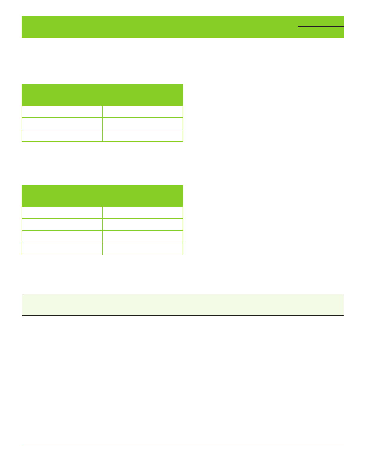
Pressure Tank/Pressure Relief Valve/Low Pressure
To maintain constant pressure and prevent frequent startup, a small-capacity pressure tank is needed in the system (refer to the minimum capacity of pressure tank table below). The VARIOspeed® 3R Duplex control panel may
use a pressure tank of a larger capacity than listed on the table below.
Minimum Capacity of Pressure Tank
Flow Rate (GPM)
Tank Size
(Total Capacity)
Less than 12.0 4 Gallons
More than 12.0 8 Gallons
More than 50.0 14 Gallons
Pre-Charge Pressure
1. Initial charge pressure should be set at 70% of the system pressure (Set pressure).
2. To maintain the optimum pressure control, check the air pressure in the tank regularly.
Set Pressure (PSI)
Initial Charging
Pressure (PSI)
50 (default) 35
55 39
60 42
65 46
A Pressure Relief Valve Must be Installed.
A pressure relief valve MUST be installed as close as possible to the pump discharge and plumbed to a drain able
to handle the full flow of the pump in the event of a malfunction.
WARNING!
Failure to use a pressure relief valve could result in burst pipes and flooding if a system failure should occur.
10 VARIOspeed® 3R Duplex User Manual
Page 11
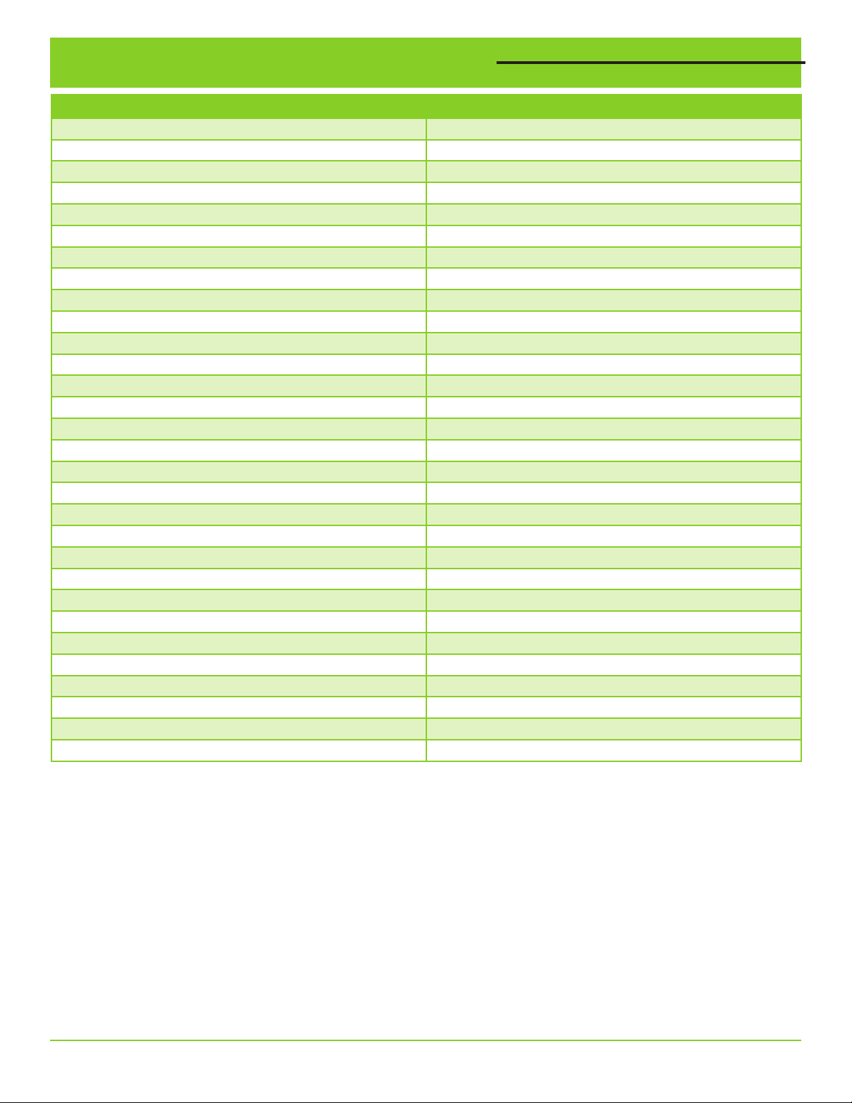
Faults, Alarms and Warning Codes
MAIN DISPLAY MESSAGE DESCRIPTION OF FAULT ALARM
COMMS LOST (P1/P2) Loss of Communications
SENSOR FAILURE Pressure Sensor Fault
HIGH PRESS WARNING High Pressure Warning
RUN DRY WARNING Run Dry Warning (Automatic Reset)
RUN DRY FAULT Run Dry Fault (Manual Reset required)
SHUTDOWN INPUT External Shutdown Input Activated
OL ACCEL (P1/P2) E.OC1 Overcurrent Trip During Acceleration
OVER CURR (P1/P2) E.OC2 Overcurrent Trip During Constant Speed
OL DECEL (P1/P2) E.OC3 Overcurrent Trip During Deceleration
OVER VOLT 1 (P1/P2) E.OV1 Regenerative Overvoltage
OVER VOLT 2 (P1/P2) E.OV2 Regenerative Overvoltage
OVER VOLT 3 (P1/P2) E.OV3 Regenerative Overvoltage Trip
VFD OL TRIP (P1/P2) E.THT Inverter Overload Trip
MOTOR OL TRIP (P1/P2) E.THM Motor Overload Trip
VFD OVERHEAT (P1/P2) E.FIN Fin Overheat
STALL PREVENTION (P1/P2) E.OLT Stall Prevention
GROUND FLT (P1/P2) E.GF Output Side Earth (ground)
OUTPUT PHASE LOSS (P1/P2) E.LF Output Phase Loss
INRUSH CURR LIMIT (P1/P2) E.IOH Inrush Current Limit Circuit
ANALOG INPUT (P1/P2) E.AIE Analog Input Fault
INPUT PHASE LOSS (P1/P2) E.ILF Input Phase Loss
BRAKE XSTR ALARM (P1/P2) E.BE Break Transistor Alarm Detection
XTRNL THERM (P1/P2) E.OHT External Thermal Relay Operation
XTRNL THERMIST (P1/P2) E.PTC PTC Thermistor Operation
VFD EEPROM FAULT (P1/P2) E.PE Parameter Storage Device Fault
DISCONNECTED PU (P1/P2) E.PUE PU Disconnection
FLT RETRY EXCEED (P1/P2) E.RET Retry Count Excess
VFD CPU FAULT (P1/P2) E.5/E.CPU CPU fault
OUTPUT AMPS DET (P1/P2) E.CDO Ouput Current Detection Value Exceeded
SAFETY CIRC FLT (P1/P2) E.SAF Safety Circuit Fault
IMPORTANT:
Faults can be reset by pressing the STOP/RESET button on the VFD. The HAND/OFF/AUTO selector switch must be
in the “OFF” position when resetting any fault. Please contact your distributor if you are unable to reset a fault by
removing power from the VFD and repowering after one minute.
VARIOspeed® 3R Duplex User Manual 11
Page 12
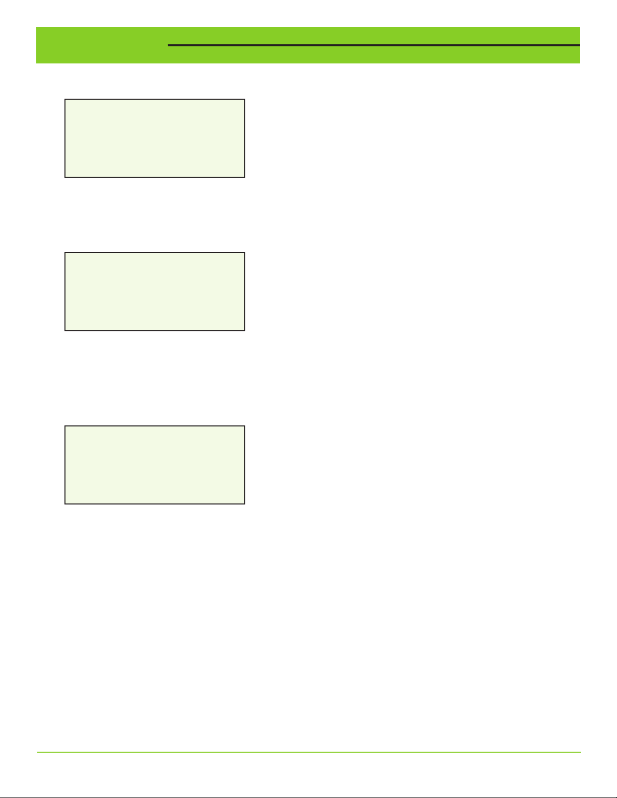
Viewing Log
Viewing Pump Motor Run Time
Pump Motor Run Time
Pump 1 1234567 hours
Pump 2 1234567 hours
The accumulated run time of the motor can be viewed by accessing the View Run Time screen in the setting menu.
The run time is displayed in total hours run.
Viewing VFD Fault History
VFD OVERLOAD TRIP
STALL PREVENTION
VFD OVERLOAD TRIP
VFD OVERLOAD TRIP
The VFD fault history of each VFD can be viewed by accessing the VFD1/VFD2 Fault History screen in the settings
menu. The last eight faults of each VFD can be viewed by scrolling through the Fault History screen, with the most
recent faults first. If a fault is currently active, the fault will flash on the main screen.
Viewing System Fault Log
- - Time Since Fault - HPress 42d 16:23:42
RunDry No Faults
ShdnIn No Faults
The System Fault Log can be viewed by accessing the View Sys Fault Log screen in the settings menu. The System
Fault Log shows the length of time since a HIGH PRESSURE CONDITION, RUN DRY CONDITION, SHUTDOWN INPUT,
PUMP1 SENSOR, or PUMP2 SENSOR FAILURE occurred. Rotating the dial allows the user to scroll through the System
Fault Log. If no fault has occurred, the “No Faults” message is shown.
12 VARIOspeed® 3R Duplex User Manual
Page 13
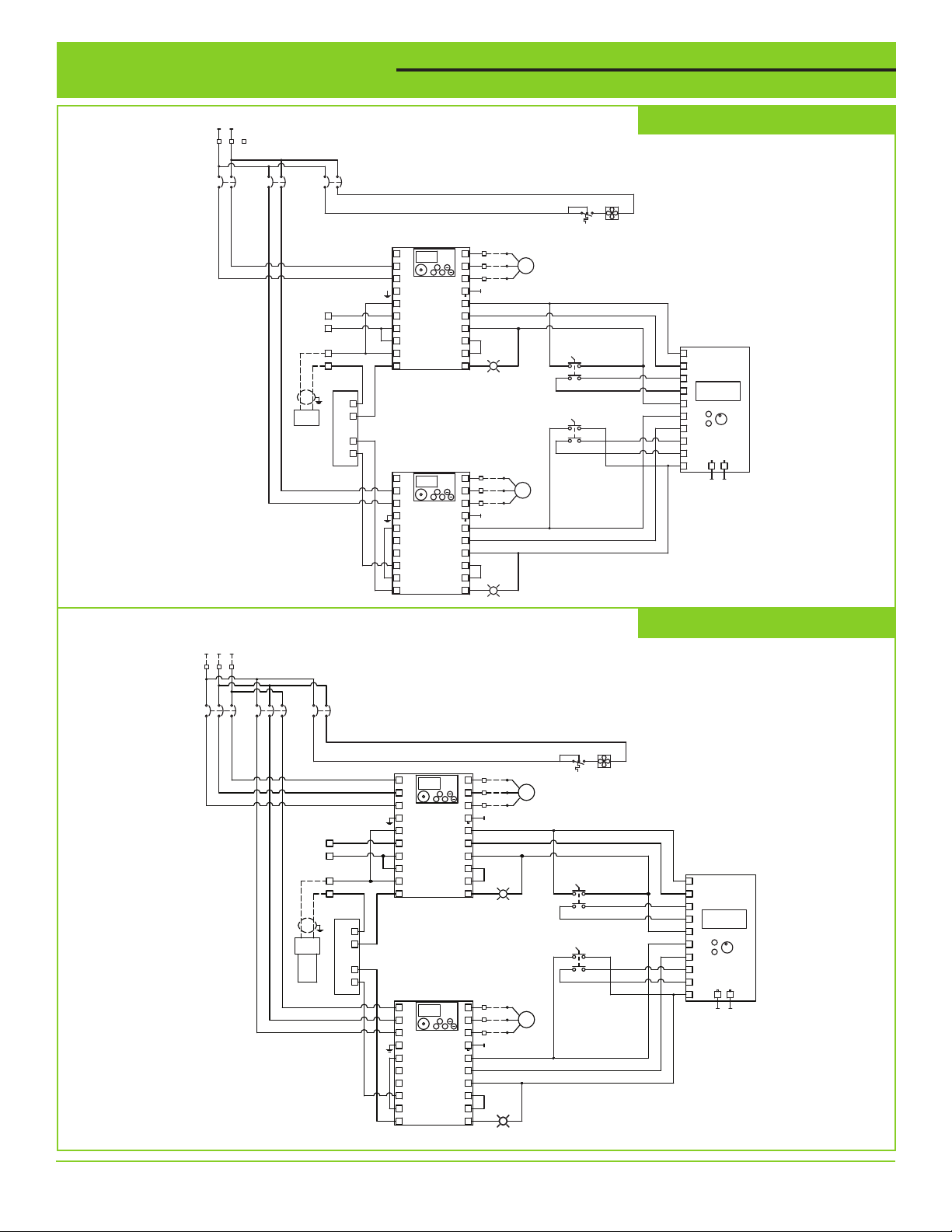
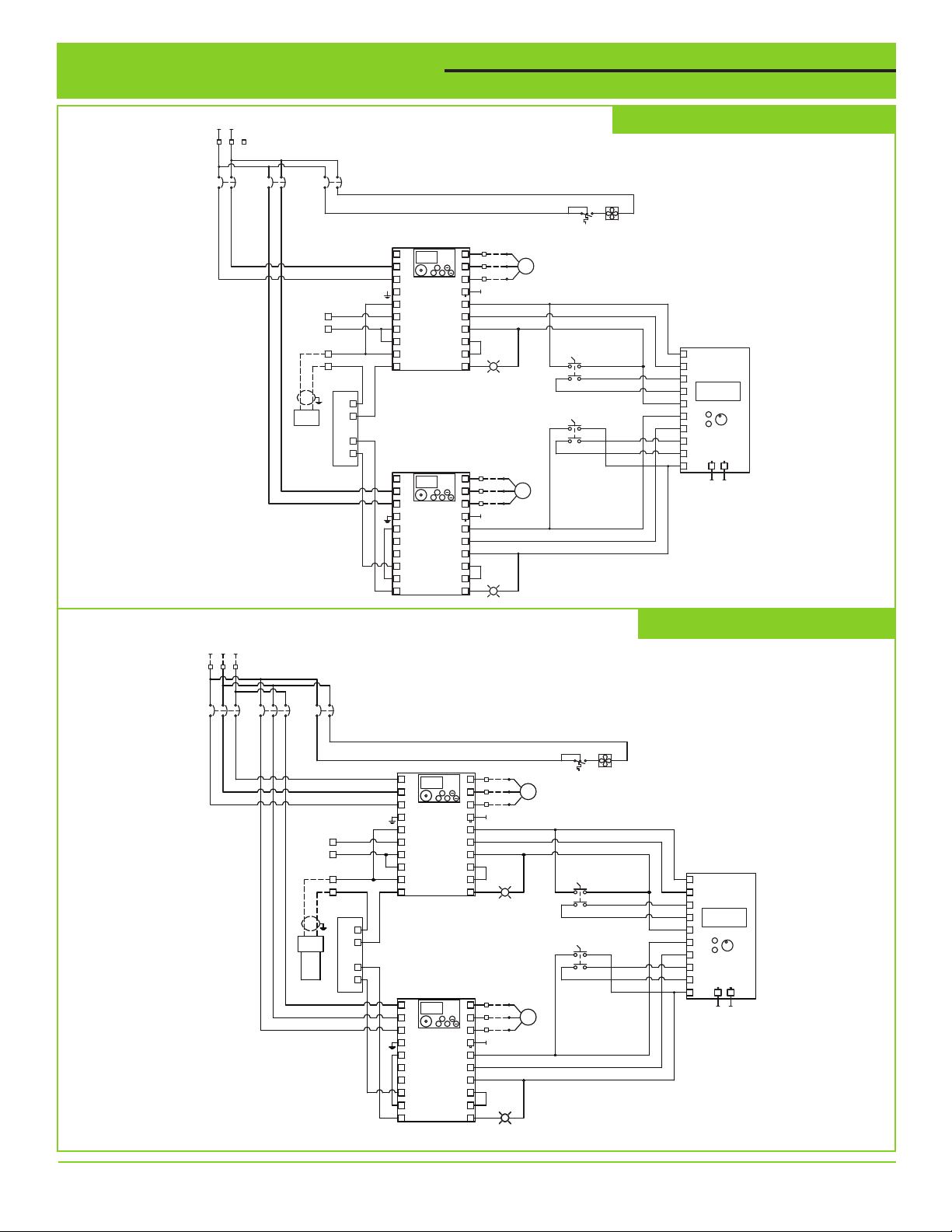
Terminal Connections
208/240 VAC
SINGLE PHASE
INCOMING POWER
L1
L2
NFC
1
2 3
DB1
208/240V-SINGLE PHASE PANELS
3
1
324
4
CB105
CIRCUIT
BREAKER
2
1
CB105.1
CIRCUIT
BREAKER
1
2
CB105.2
CIRCUIT
BREAKER
4
3
TS136 FAN136
FAN
THERMOSTAT
TB2
3
RUN MON_PRM
SHUTDOWN
INPUT
RED
BLACK
PRESSURE
TRANSDUCER
200 PSI
T/L3
S/L2
R/L1
G
TB1
3
4
TB1
1
2
SE
RM
SD
5
PC
4
VARIABLE FREQUENCY DRIVE
IN+
IN-
LOOP
ISOLATOR
OUT+
OUT-
T/L3
S/L2
R/L1
G
SE
RM
SD
5
PC
4
VARIABLE FREQUENCY DRIVE
D700 DRIVE
VFD112
D700 DRIVE
VFD129
W
PU_EXT NET
2
STOP
V
RUN
RESET
PU
SET
MODE
EXT
1
U
PU
A/1.29
RH
STF
SD
RL
SO
LT120
RUN
PUMP 1 RUN
TB2
6
RUN MON_PRM
W
PU_EXT NET
5
STOP
V
RUN
RESET
PU
SETMODE
EXT
4
U
PU
B/1.29
RH
STF
SD
RL
SO
LT138
RUN
PUMP 2 RUN
3 PHASE
PUMP 1
PUMP 1
HOA
2324
G
XOO
1314
OOX
PUMP 2
HOA
2324
XOO
1314
OOX
MTR112
PUMP 2
208/240VAC
3 PHASE
1
2
3
4
5
6
7
8
9
10
B/1.32
A/1.14
G
208/240 VAC
THREE PHASE
INCOMING POWER
L1
L2
L3
1
2 3
DB1
31 5
642
CB105
CIRCUIT
BREAKER
31 5
642
CB105.1
CIRCUIT
BREAKER
TRANSDUCER
SHUTDOWN
INPUT
RED
PRESSURE
200 PSI
142
3
BLACK
208/240V-3 PHASE PANELS
CB105.2
CIRCUIT
BREAKER
TS110
FAN110
T/L3
S/L2
R/L1
G
TB1
3
4
TB1
1
2
SE
RM
SD
5
PC
4
VARIABLE FREQUENCY DRIVE
D700 DRIVE
VFD112
W
PU_EXT NET
2
STOP
V
RUN
RESET
PU
SET
MODE
EXT
1
U
PU
A/1.29
RH
STF
SD
RL
SO
RUN
PUMP 1 RUN
LT120
208/240VAC
PUMP 1
3 PHASE
G
TB2
3
RUN MON_PRM
IN+
IN-
LOOP
ISOLATOR
OUT+
OUT-
TB2
6
5
4
B/1.29
LT138
G
PUMP 2 RUN
MTR112
PUMP 2
208/240VAC
3 PHASE
RUN MON_PRM
T/L3
PU_EXT NET
STOP
S/L2
RUN
RESET
SETMODE
R/L1
D700 DRIVE
G
SE
RM
SD
VFD129
5
PC
4
VARIABLE FREQUENCY DRIVE
W
V
PU
EXT
U
PU
RH
STF
SD
RL
SO
RUN
THERMOSTAT
PUMP 1
O
H
PUMP 2
HOA
FAN
A
XOO
2324
OOX
1314
1
2
3
4
5
XOO
2324
OOX
1314
6
7
8
9
10
B/1.32
A/1.14
VARIOspeed® 3R Duplex User Manual 13
Page 14
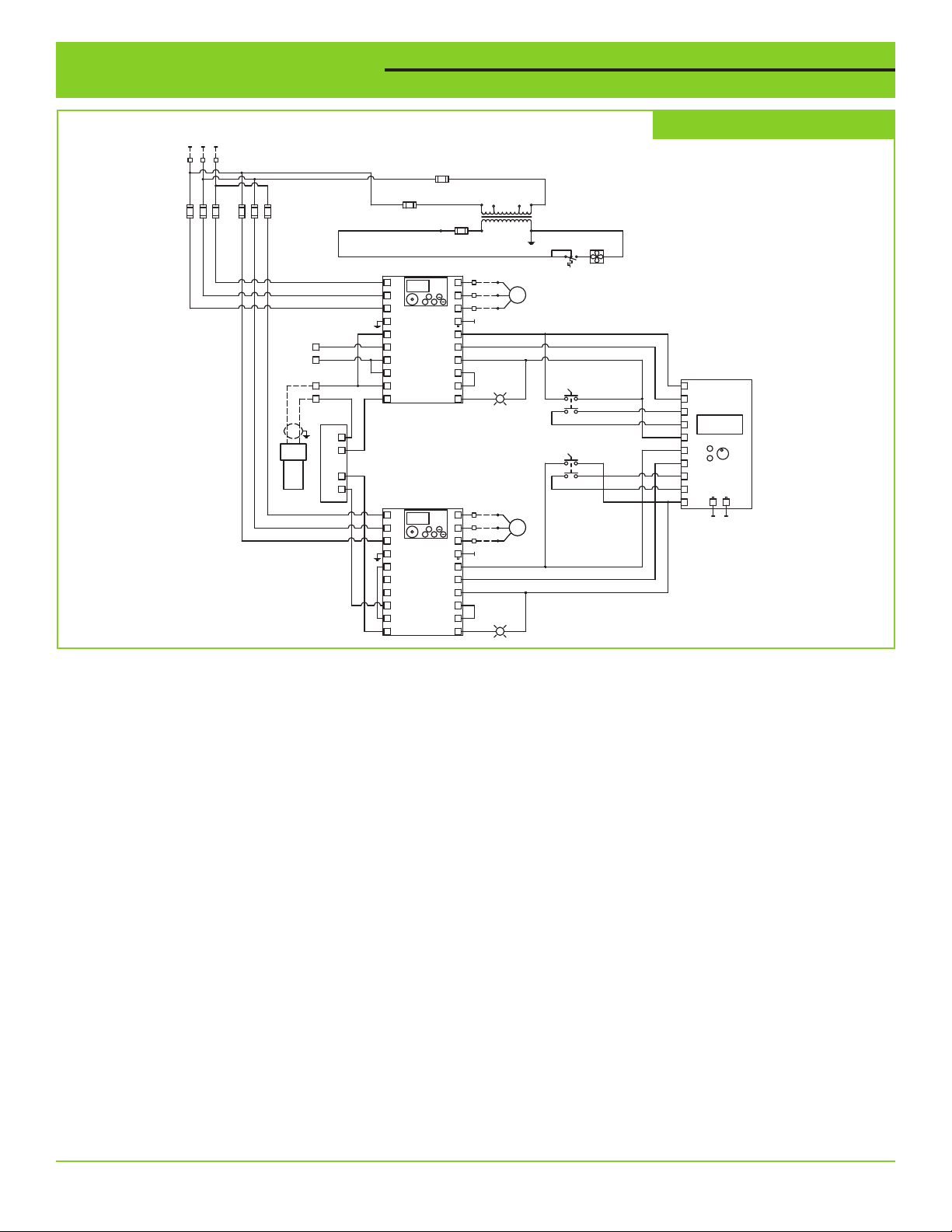
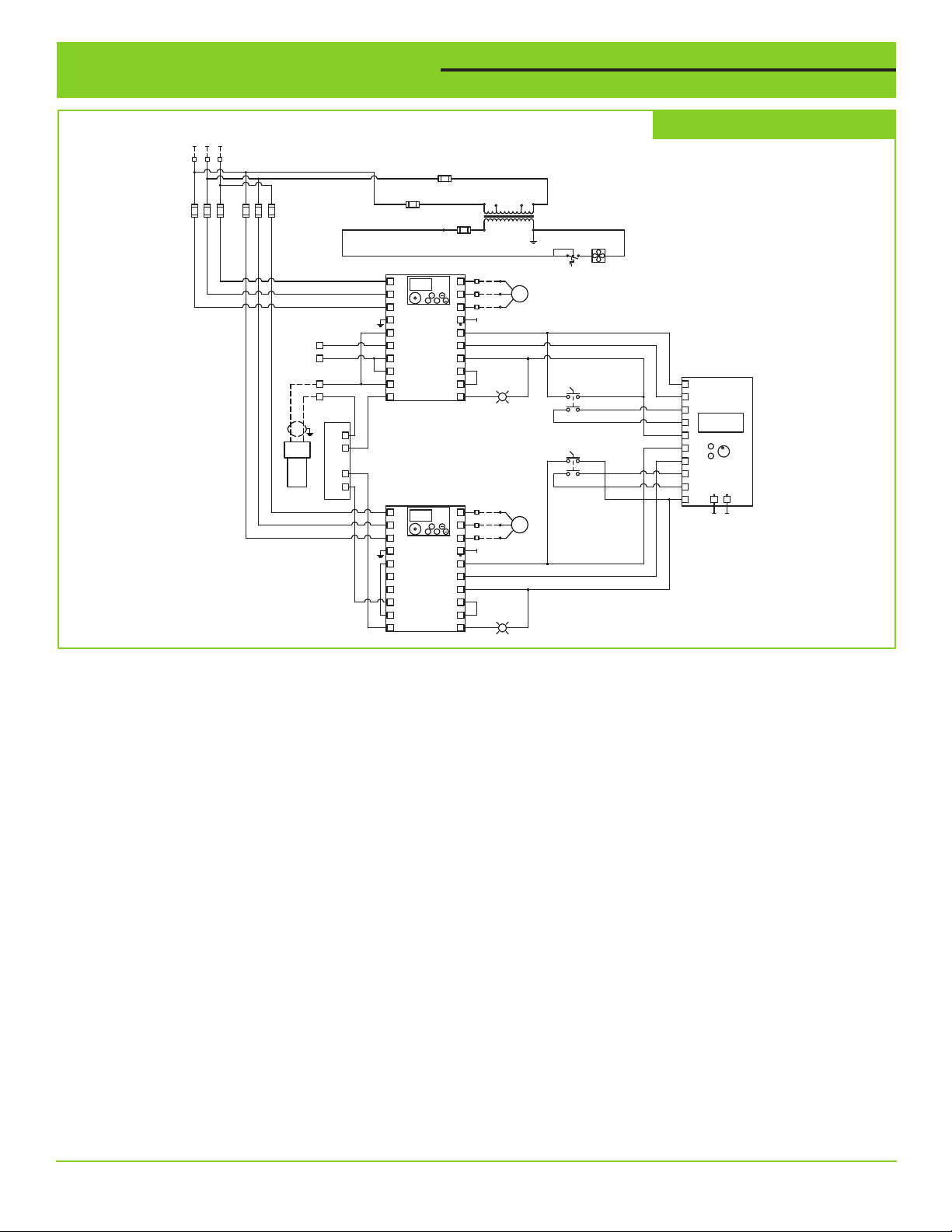
Terminal Connections
PUMP 1
480 VAC
THREE PHASE
INCOMING POWER
L1 L2 L3
2 31
DB1
FUSE
HOLDER
FUSE
HOLDER
TRANSDUCER
SHUTDOWN
INPUT
RED
PRESSURE
200 PSI
BLACK
TB1
3
4
TB1
1
2
IN+
IN-
LOOP
ISOLATOR
OUT+
OUT-
FU103
1 AMP
CLASS CC FUSE
FU105
1 AMP
CLASS CC FUSE
XF
RUN MON_PRM
T/L3
PU_EXT NET
STOP
S/L2
RUN
RESET
PU
SETMODE
D700 DRIVE
VFD112
D700 DRIVE
VFD129
RUN MON_PRM
RUN
EXT
RUN
PU_EXT NET
STOP
RESET
PU
SETMODE
EXT
RUN
R/L1
G
SE
RM
SD
5
PC
4
VARIABLE FREQUENCY DRIVE
T/L3
S/L2
R/L1
G
SE
RM
SD
5
PC
4
FU107
6/10 AMP, 250V
MIDGET FUSE
W
V
U
PU
RH
STF
SD
RL
SO
W
V
U
PU
RH
STF
SD
RL
SO
TB2
3
2
1
TB2
6
5
4
A/1.29
LT120
PUMP 1 RUN
B/1.29
LT138
480V-3 PHASE PANELS
460V
H2H3
H1H4
T105
115V
X2X1
TS109 FAN109
GRD
FAN
THERMOSTAT
208/240VAC
PUMP 1
3 PHASE
PUMP 1
O
A
H
XOO
G
2324
OOX
1314
PUMP 2
HOA
XOO
2324
OOX
1314
MTR112
PUMP 2
208/240VAC
3 PHASE
G
1
2
3
4
5
6
7
8
9
10
B/1.32
A/1.14
14 VARIOspeed® 3R Duplex User Manual
Page 15
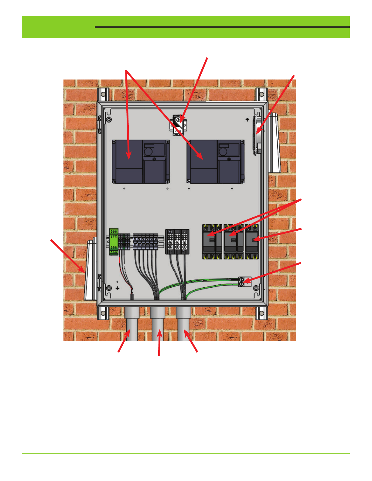
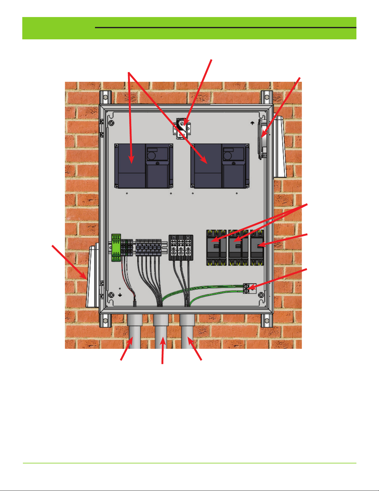
Installation
Vent
Variable Frequency Drive
Thermostat
(VFD)
Fan
Pump Circuit
Breakers
Fan Control
Circuit
Breaker
Pressure
Transducer
Conduit
Motor
Cable
Conduit
Ground
Terminals
Input
Power
Conduit
VARIOspeed® 3R Duplex User Manual 15
Page 16

Notes: ________________________________________________________________________________
______________________________________________________________________________________
______________________________________________________________________________________
______________________________________________________________________________________
______________________________________________________________________________________
______________________________________________________________________________________
______________________________________________________________________________________
______________________________________________________________________________________
______________________________________________________________________________________
______________________________________________________________________________________
______________________________________________________________________________________
______________________________________________________________________________________
______________________________________________________________________________________
______________________________________________________________________________________
______________________________________________________________________________________
______________________________________________________________________________________
______________________________________________________________________________________
______________________________________________________________________________________
______________________________________________________________________________________
______________________________________________________________________________________
______________________________________________________________________________________
+ 1-800-746-6287
www.sjerhombus.com
Technical Support Hours: Monday - Friday 7 A.M. to 6 P.M. Central Time
© 2019 SJE, Inc. All Rights Reserved.
SJE RHOMBUS is a trademark of SJE, Inc.
16 VARIOspeed® 3R Duplex User Manual
PN 1051668B 12/19
Page 17
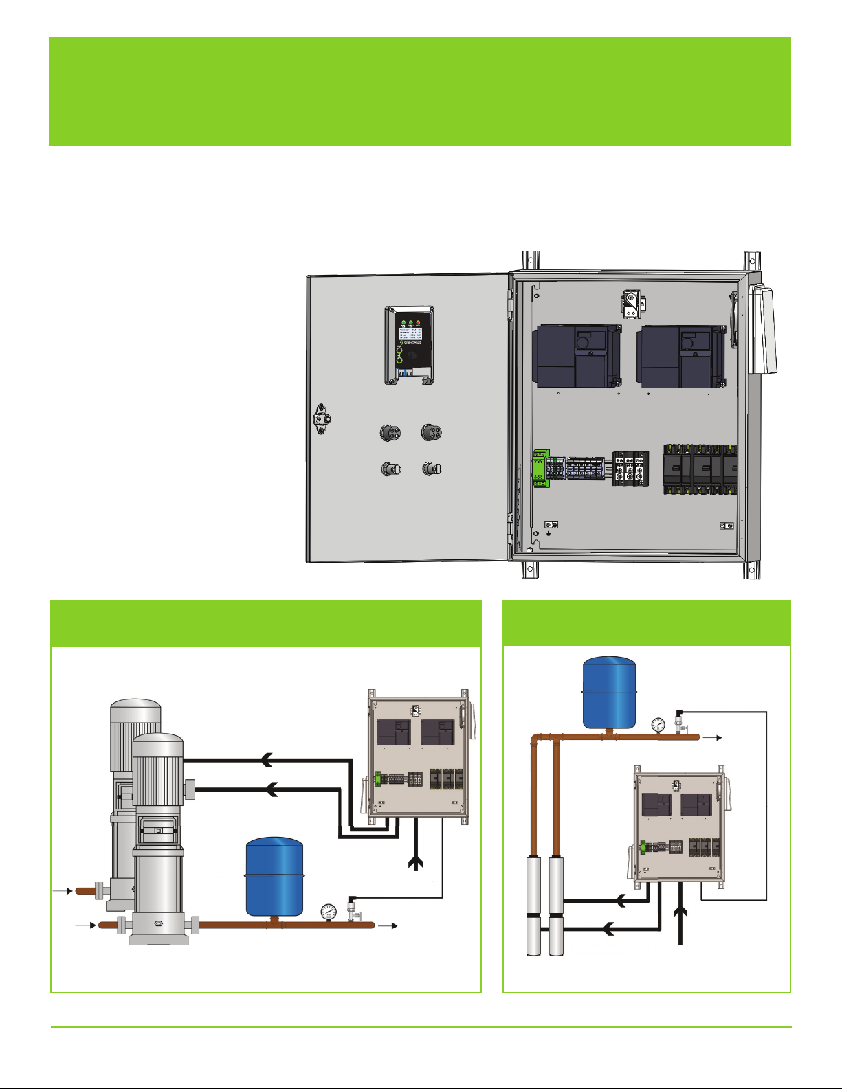
VARIOspeed®3R Dúplex
Manual del usuario
Este panel de control VARIOspeed® viene diseñado para el control constante de la presión en su sistema de bombeo.
En caso de ser necesario realizar pequeños ajustes, por favor consulte la tabla de parámetros incluida en este
documento.
Si requiere asistencia, por favor comuníquese con la fábrica.
Aplicación con bombas de refuerzo de presión
Motor trifásico de la bomba
Tanque
de presión
Transductor
de presión
Corriente
de entrada
Aplicación con bombas sumergibles
en pozos profundos
Tanque
de presión
Bomba de pozo
Motor trifásico
Transductor
de presión
Corriente
de entrada
VARIOspeed® 3R Dúplex - Manual del usuario 1
Page 18
ADVERTENCIAS
Es obligatorio leer y comprender la información suministrada en este manual el no hacerlo podría
ocasionar lesiones personales o mortales, daños al producto o falla de este. Por favor lea cada
sección en su totalidad y asegúrese de comprender la información suministrada en las secciones
relacionadas antes de intentar algunos de los procedimientos u operaciones indicadas.
De no tomarse estas precauciones, pueden ocasionarse lesiones serias o mortales.
Después de la instalación, guardar estas instrucciones junto con la garantía. Este producto
debe ser instalado siguiendo el Código Eléctrico Nacional de EE.UU., ANSI/NFPA 70, para
evitar la entrada o acumulación de humedad al interior del gabinete del controlador.
Ver las especificaciones adicionales en la página 3 de este manual.
RIESGO DE CHOQUE ELÉCTRICO
Desconecte la fuente de alimentación al panel VARIOspeed® 3R Dúplex
y espere 10 minutos antes de quitar las cubiertas del VFD. La instalación
y el mantenimiento de este producto deben ser efectuados por personal
idóneo siguiendo las normas aplicables en cuanto a instalaciones eléctricas
y diagramas eléctricos.
• Aún después de desconectada la alimentación, al interior del panel VARIOspeed® 3R Dúplex
circulan voltajes letales. Espere 10 minutos para que los condensadores internos puedan
descargarse completamente antes de intentar la conexión o desconexión de cables o de hacerle
mantenimiento a este equipo.
• No conecte la corriente de entrada a las terminales U, V y W del motor. Al hacerlo producirá
daños irreversibles en el variador.
• No conecte la alimentación a este equipo si está dañado o le hacen falta piezas.
• Compruebe que el voltaje de alimentación corresponda al de la entrada nominal del variador antes
de aplicar corriente a la unidad.
• Los VFD VARIOspeed® 3R Dúplex no incluyen piezas que se puedan reparar. Por consiguiente,
no intente la reparación de este equipo.
®
• El panel VARIOspeed
establecido en el Código Eléctrico Nacional de EE.UU. Consulte la información sobre la conexión
eléctrica en las páginas 13-14.
• No instalarlo en áreas expuestas a: excesiva presencia de polvo o de polvos conductores, gas
corrosivo o inflamable, calor excesivo, choques mecánicos de impacto constante o exceso de
vibración.
• No instalarlo en áreas con temperatura ambiente por encima de 40 ºC (104 ºF).
3R Dúplex debe estar conectado a tierra en la terminal de tierra según lo
RIESGO DE INCENDIO O EXPLOSIÓN
No utilice este producto con líquidos inflamables. No lo instale en
lugares peligrosos definidos como tales en el Código Eléctrico Nacional
de EE.UU., ANSI/NFPA 70.
2 VARIOspeed® 3R Dúplex - Manual del usuario
Page 19
Especificación / Selección
PESO
PARTE
No. DESCRIPCIÓN MODELO
1051672 VARIOspeed® 3R Dúplex, 240V VS21-7.0-N3RD 7, 0 1,5 1 3 115 lb
1051673 VARIOspeed® 3R Dúplex, 240V VS21-10.0-N3RD 10,0 3 1 3 115 lb
1051674 VARIOspeed® 3R Dúplex, 240V VS23-16.5-N3RD 16,5 5 3 3 115 lb
1051675 VARIOspeed® 3R Dúplex, 240V VS23-31.8-N3RD 31,8 7,5-10 3 3 146 lb
1051676 VARIOspeed® 3R Dúplex, 240V VS23-45.0-N3RD 45,0 15 3 3 154 lb
1051677 VARIOspeed® 3R Dúplex, 240V VS23-58.0-N3RD 58,0 20 3 3 154 lb
1051678 VARIOspeed® 3R Dúplex, 480V VS43-16.0-N3RD 16,0 7,5-10 3 3 150 lb
1051679 VARIOspeed® 3R Dúplex, 480V VS43-29.5-N3RD 29,5 15-20 3 3 161 lb
Nota:
Los límites de potencia (caballaje, HP) se basan en el motor NEMA B de cuatro polos (usado exclusivamente como indicación; seleccione el tamaño adecuado del VFD según el amperaje a plena carga, FLA, indicado en la placa del motor).
El voltaje de salida del VFD no debe exceder el voltaje de entrada. Ejemplo: entrada de 208V, salida de 208V (máx).
Cómo seleccionar el VFD correcto
1. Determine el voltaje disponible en el sitio de instalación.
2. Seleccione bombas con el mismo voltaje (el motor debe ser trifásico).
3. Compruebe el amperaje a plena carga (FLA) del motor de la bomba para seleccionar el tamaño adecuado del VFD.
4. Seleccione un VFD con un amperaje de salida nominal superior al amperaje a plena carga (FLA) del motor.
5. Para seleccionar el tamaño del VFD, utilice los Amperios de Factor de Servicio (SFA) del motor correspondientes a
aplicaciones con bombas sumergibles en pozos.
SALIDA
(A) HP
FASE
ENTRADA
FASE
SALIDA
DE
EMBARQUE
Conversión de fase
En los modelos VS23 es posible suministrar una potencia de entrada monofásica de 240V. Al amperaje de salida del VFD
debe aplicarse una reducción de 50%.
Ejemplo: El VS23-45.0-N3RD será reducido a una salida de 22,5 A (máx).
*Use una corriente de entrada trifásica cuando esté disponible. Los VFD VS23 no tiene certicación UL con alimentación monofásica.
Siempre use un motor trifásico.
Longitud máxima del cable del motor
Para bombas de 208V-240V: 122 m (400 pies) - Para longitudes de cable superiores a 122 m (400 pies), use un reactor de
carga en cada bomba. No exceda los 244 metros (800 pies).
Para bombas de 480V: 15 m (50 pies) - Para longitudes de cable superiores a 15 m (50 pies), use un reactor de carga en
cada bomba. No exceda los 91 metros (300 pies).
Ambiente
Temperatura de operación: -10 ºC a 40 ºC (14 ºF a 104 ºF)
Temperatura de almacenamiento: -20 ºC a 55 ºC (-4 ºF a 131 ºF)
Altitud: máxima de 1.000 m (3.280 pies) por encima del nivel del mar
VARIOspeed® 3R Dúplex - Manual del usuario 3
Page 20
Opciones de pantalla y Navegación
BOMBA 1 y BOMBA 2
Frecuencia de salida
BOMBA 1 y BOMBA 2
Estado, principal/reserva
Tecla de escape:
se usa para salir del
sistema sin guardar
los valores de
configuración o para
regresar a la pantalla
principal del monitor.
Tecla izquierda:
se usa para
seleccionar
dígitos durante
la edición.
BOMBA 1
Indicador de
funcionamiento
BOMBA 2
Indicador de
funcionamiento
Indicador de fallo
Presión actual
Presión
predeterminada
BOMBA 1 y BOMBA 2
Corriente del motor
Tecla Intro giratoria/
de pulsar:
se usa para
desplazarse por el
menú y editar
los valores de
configuración.
Ejemplos de programación
Para cambiar el amperaje de sobrecarga del motor de la Bomba 1
1. Desde la pantalla principal, pulse la tecla izquierda o la tecla Intro para ingresar al menú de configuración.
Set Pressure
OR
2. Rote el selector giratorio (tecla Intro) hasta que la flecha resalte la opción “Set Pump 1 Motor OL Amps” (Configurar
protección de sobrecarga del motor de la Bomba 1, en amperios).
Set Lag Stop Di
Set Lag Stop Time
Set Alternation Time
Set Pump 1 OL Amps
4 VARIOspeed® 3R Dúplex - Manual del usuario
Set Start Di Press
Set Lag Start Di
Set Lag Stop Di
Page 21
Set Pump 1 Current
12.3 Amps
(Use nameplate data)
Min 0 Max 60
Ejemplos de programación
3. Pulse el selector giratorio (tecla Intro) para editar la opción "Pump 1 Current" (corriente de la Bomba 1).
4. Rote el selector para comenzar a editar el valor. Al pulsar la tecla izquierda (que tiene una flecha), la posición cambia
al dígito a la izquierda para editarlo. Esto es útil para ajustar rápidamente valores más grandes.
Set Pump 1 Current
OR
5. Pulse el selector para guardar el valor editado y salir de la pantalla de edición. Alternativamente, pulse la tecla ESC
(escape) para salir de la pantalla de edición sin guardar los cambios.
+
13.3 Amps
(Use nameplate data)
Min 0 Max 60
Set Lag Stop Di
OR
Set Lag Stop Time
Set Alternation Time
Set Pump 1 OL Amps
5. Si no es necesario editar otros parámetros, pulse la tecla ESC para regresar a la pantalla principal.
MENU DE CONFIGURACIÓN DE PARÁMETROS + REGISTRO DE DATOS
Set Pressure Set Pump 2 Voltage Set 1st Decel Time
Set Start Diff Pres Set Sleep Frequency Set Accel 2 Sw Freq
Set Lag Start Diff Set Sleep Time Set Acc/Dec Time
Set Lag Stop Diff Set Xducer Max Range Set High Press Alarm
Set Lag Stop Time Set Min Frequency Set Run Dry Press
Set Alternation time Set Max Frequency Set Run Dry Restart
Set Pump 1 OL Amps Set PID Prop Term View Run Times
Set Pump 1 Voltage Set PID Integ Term View VFD1 Fault Hist
Set Pump 2 OL Amps Set 1st Accel Time View VFD2 Fault Hist
VARIOspeed
®
3R Dúplex - Manual del usuario 5
View Error Log
Page 22
Operación HAND / OFF / AUTO (Manual / Apagado / Auto)
P. 004
P. 000
P. 004
P. 000
60.00
55.00
55.00
P. 004
P. 000
P. 004
P. 000
60.00
Presión configurada
Nivel de presión
de arranque
Arranque de la bomba
Hz, motor
Presión de descarga
Seg.
Presión
Presión configurada
Presión de arranque
Hz
Posición HAND (Manual)
La bomba va a operar a velocidad constante. La frecuencia en modo manual (HAND) puede configurarse ingresando
un valor en P.4. NOTA: en modo manual (HAND) no se monitorea la presión del sistema, o sea que el sistema debe ser
supervisado constantemente durante el uso.
Cómo cambiar la velocidad de referencia manual (HAND) (en cada VFD)
1. En el VFD, pulse MODE para seleccionar el modo de configuración de
parámetros.
P. 000
(El parámetro leído
previamente aparece).
2. Gire el dial de configuración SETTING DIAL hasta que aparezca P.4.
3. Pulse SET (configurar) para leer el valor de la velocidad manual actu-
al. En pantalla aparece “60.00” (valor inicial).
4. Gire el dial de configuración SETTING DIAL para cambiar a la nueva
velocidad manual de “55.00”.
5. Pulse SET para guardar el valor. Parámetro aparece de modo
intermitente --- Finaliza la configuración de parámetros.
• Pulse MODE dos veces para regresar al monitor de frecuencia.
Posición OFF (Apagado)
La bomba no opera.
Posición AUTO (Automático)
La bomba principal no opera si la presión
está por encima de la presión configurada
(Set Pressure). La bomba principal arranca
automáticamente si la presión cae por
debajo de la Presión configurada menos la
Presión diferencial de arranque (Start Diff.
Press.). Ejemplo: cuando la Presión configurada (Set Pressure) es 40 PSI y la Presión
diferencial de arranque (Start Diff Pressure)
es 5 PSI. La bomba principal va a arrancar
cuando la presión descienda a menos de
35 PSI (véase el ejemplo a continuación).
La bomba de reserva va a arrancar cuando
la bomba principal esté operando a máxima
velocidad y la presión esté por debajo de la
presión configurada (Set Pressure) menos la
presión diferencial de arranque de la bomba de reserva (Lag Start Differential) durante cinco segundos. La bomba de
reserva va a operar a máxima velocidad cuando esté funcionando. La bomba de reserva se detendrá cuando la presión
exceda la presión configurada (Set Pressure) más la presión diferencial de arranque de la bomba de reserva (Lag Start
Differential) durante el tiempo de parada de la bomba de reserva (Lag Stop Time).
Apagado del sistema por fallo en el transductor de presión
En caso de perderse la señal del transductor de presión, el sistema apagará la(s) bomba(s). Durante el error por fallo en
el transductor, la pantalla principal indicará de modo intermitente “SENSOR FAILURE” (Fallo del sensor) y se iluminará
el indicador de fallos. Una vez corregido el fallo del transductor, la pantalla vuelve a la condición normal y continuará el
control normal de la presión.
P. 004
60.00
55.00
6 VARIOspeed® 3R Dúplex - Manual del usuario
Page 23
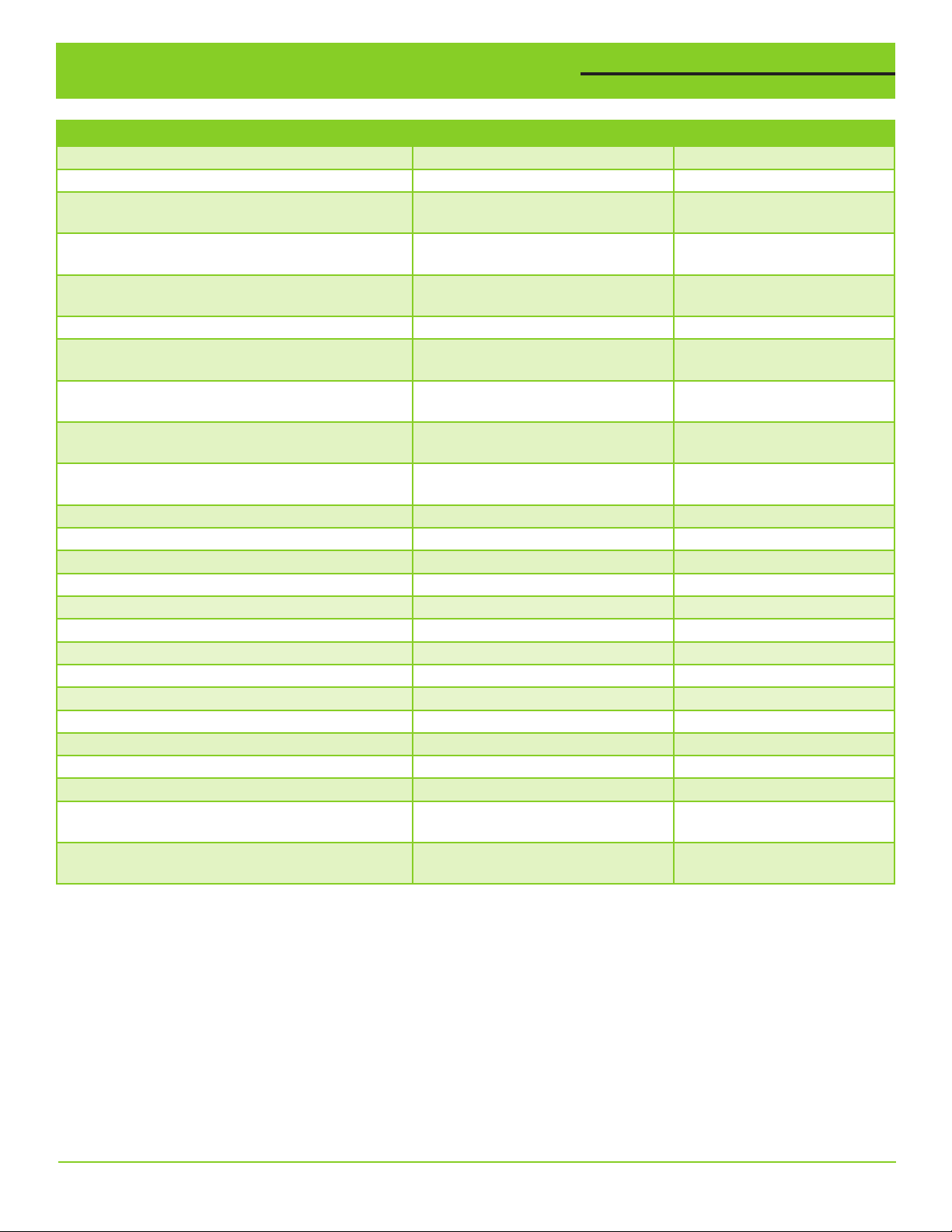
Configuración de parámetros - Lista
DESCRIPCIÓN DEL PARÁMETRO RANGO VALOR POR DEFECTO
Set Pressure (Presión configurada) 0 a “Xducer Max Range” - 0,1 60,0 PSI
Start Diff Pressure (Presión diferencial de arranque)
Lag Start Diff Pressure (Presión diferencial,
arranque de la bomba de reserva)
Lag Stop Diff Pressure (Presión diferencial, parada
de la bomba de reserva)
Lag Stop Delay Time (Tiempo de espera, parada de
la bomba de reserva)
Alternation Time (Tiempo de alternación) 1 a 168 horas 24 horas
Pump 1 OL Amps (Amperaje Bomba 1, protección de
sobrecarga)
Pump 1 Voltage (Bomba 1, voltaje) 0 a 1000 voltios Específico a cada modelo
Pump 2 OL Amps (Amperaje Bomba 2, protección de
sobrecarga)
Pump 2 Voltage (Bomba 2, voltaje) 0 a 1000 voltios Específico a cada modelo
Sleep Frequency (Frecuencia de inactividad) 0 a “Max Frequency” 35.0 Hz
Sleep Time (Tiempo de inactividad) 0 a 3600 segundos 10 segundos
Xducer Max Range (Rango máximo del transductor)
Min Frequency (Frecuencia mínima) 0 a “Max Frequency” 30.0 Hz
Max Frequency (Frecuencia máxima) De “Min Frequency” a 120 Hz 60,0 HZ
PID Proportional Term (Término proporcional del PID)
PID Integral Term (Término integral del PID) 0,1 a 3600 segundos 1,0 segundos
1st Accel Time (Tiempo 1a Aceleración) 0 a 3600 segundos 2 segundos
1st Decel Time (Tiempo 1a Desaceleración) 0 a 3600 segundos 2 segundos
Accel 2 Switchover Freq (Acel 2 - Frec. de cambio) 0 a “Max Frequency” 30 Hz
Accel/Decel Time (Tiempo de Acel/Desacel) 0 a 3600 segundos 3 segundos
High Pressure Alarm (Alarma de presión alta) 0 a “Xducer Max Range” - 0,1 90,0 PSI
Run Dry Pressure (Funcionamiento en seco - Presión)
Run Dry Delay Time (Funcionamiento en seco -
Tiempo de espera)
Run Dry Restart Time (Funcionamiento en seco -
Tiempo de reinicio)
0 a “Set Pressure” - 1
0 a “Set Pressure” - 1
0 a “Xducer Max Rng” - “Set Pressure” 5,0 PSI
0 a 999 segundos 2,0 segundos
0 a “VFD Amp Rating” (Amperaje
nominal del variador)
0 a “VFD Amp Rating” (Amperaje
nominal del variador)
0 a 1000 PSI 200 PSI
0,1 a 1000% 100,0%
0 a “Set Pressure” - 1
0 a 6,0 minutos 0,5 minutos
0 a 999,9 minutos 0,0 minutos (reinicio manual)
5 PSI
7,0 PSI
Específico a cada modelo
(240/480)
Específico a cada modelo
(240/480)
15 PSI
Set Pressure (Presión configurada)
La presión configurada es la presión que se debe mantener en la descarga de la bomba. No puede exceder el rango
máximo del transductor de presión.
Start Diff Pressure (Presión diferencial de arranque)
La Presión diferencial de arranque es la cantidad de caída de presión con respecto al valor de la Presión configurada
a la que el VFD principal va a despertar del modo inactivo y entra en funcionamiento para mantener la presión del
sistema. La bomba principal arranca si la caída de presión es inferior a la Presión configurada menos la Presión diferencial de arranque (Start Diff.). Ejemplo: si la Presión configurada (Set Pressure) es 40 PSI y la Presión diferencial de
arranque es 5 PSI, la bomba principal arrancará cuando la presión descienda por debajo de 35 PSI.
VARIOspeed
®
3R Dúplex - Manual del usuario 7
Page 24
Configuración de parámetros - Lista
Lag Start Diff Pressure (Presión diferencial de arranque de la bomba de reserva)
La Presión diferencial de arranque de la bomba de reserva es la cantidad de caída de presión con respecto a la Presión
configurada al tiempo que el VFD principal está operando a máxima velocidad y han transcurrido cinco segundos, pero
antes de que arranque el VFD de reserva. El VFD de reserva operará a máxima velocidad cuando esté funcionando. El
VFD principal no podrá entrar en modo inactivo cuando esté en funcionamiento el VFD de reserva.
Lag Stop Diff Pressure (Presión diferencial de parada de la bomba de reserva)
La presión diferencial de parada de la bomba de reserva es la cantidad de presión por encima de la Presión configurada,
después de transcurrido el Tiempo de parada de la bomba de reserva y antes de que se detenga el VFD de reserva.
Alternation Time (Tiempo de alternación)
El Tiempo de alternación es el tiempo de operación acumulado para el VFD principal en ese memento, antes de transferir la operación principal al otro VFD. El Tiempo de alternación tiene por objeto nivelar el desgaste de los VFD mediante la transferencia de la operación principal después de un período de operación previamente configurado.
Pump 1/Pump 2 OL Amps (Amperaje, protección de sobrecarga del motor, Bomba 1 / 2)
La sobrecarga electrónica del VFD señala fallos por sobrecarga y protege el motor contra daños en caso de una
condición de sobrecarga. Configurar el amperaje de sobrecarga del motor de las bombas 1 y 2 (Pump1/Pump 2 Motor OL
Amps) al valor a plena carga (FLA) que figura en la placa del motor en el caso de bombas no sumergibles, y al Máximo
amperaje del motor (Motor Max Amps) para bombas sumergibles.
Pump 1/Pump 2 Voltage (Tensión de las Bombas 1 / 2)
Ajustar la tensión del motor de las Bombas 1 y 2 al valor nominal indicado en la placa del motor. Este valor no debe
exceder el voltaje de la corriente de entrada.
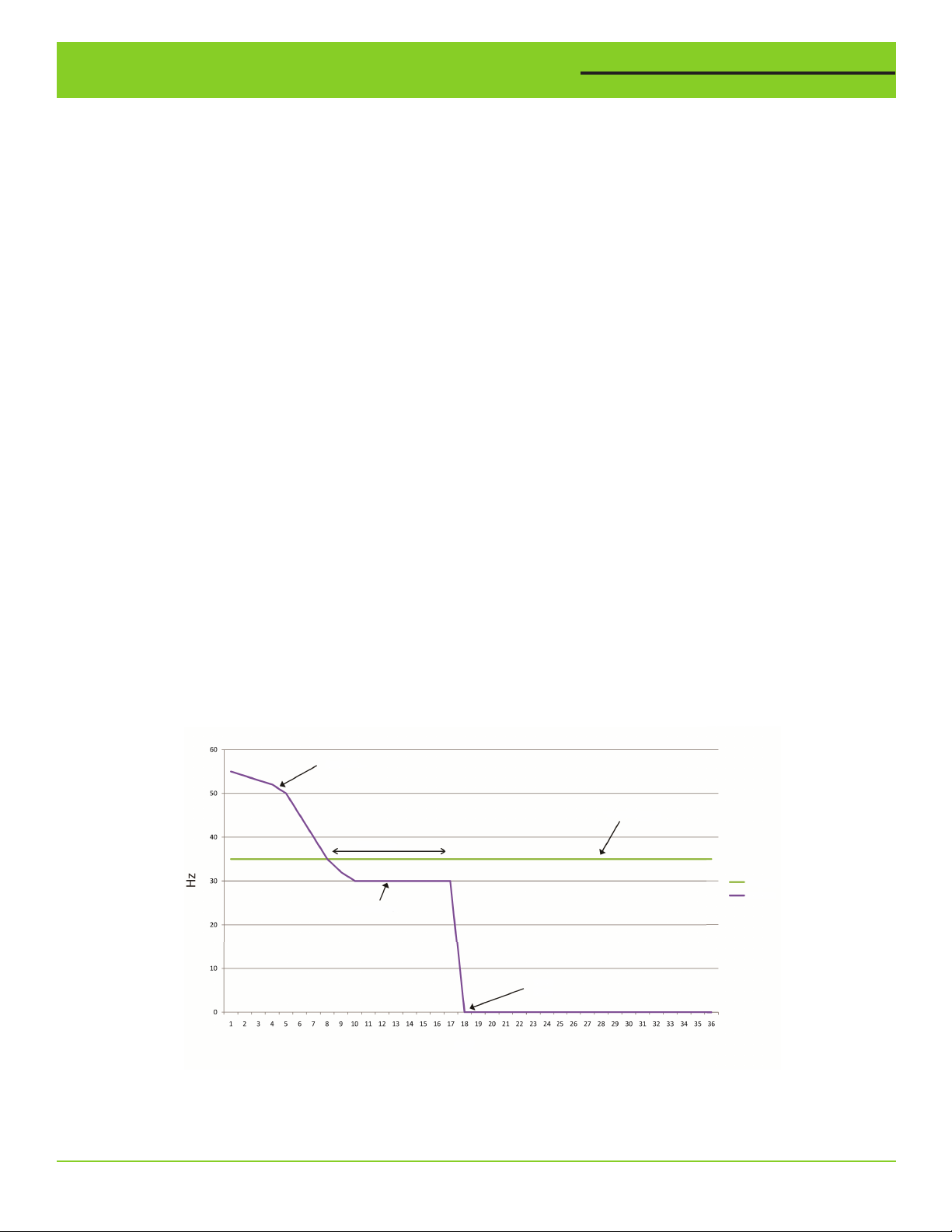
Sleep Frequency (Frecuencia de inactividad)
Ajustar el valor de la frecuencia de inactividad a la frecuencia a la cual ya no se acumula presión en la bomba principal cuando
está operando a la Presión configurada o cerca de dicho valor. El VFD principal ingresa al modo de inactividad cuando la frecuencia de salida del VFD principal desciende por debajo de la Frecuencia de inactividad por un período de tiempo (Tiempo de inactividad, Sleep Time). La función de inactividad está suspendida temporalmente cuando el VFD de reserva está en operación.
Sleep Time (Tiempo de inactividad)
Ajustar la frecuencia de inactividad al valor al cual la bomba principal no acumula presión cuando está operando a
la Presión configurada o cerca de dicho valor. El VFD principal entra en modo de inactividad cuando la frecuencia de
salida del VFD principal desciende por debajo de la Frecuencia de inactividad por un período de tiempo (Tiempo de
inactividad, Sleep Time). Cuando el VFD de reserva está en operación, queda suspendida temporalmente la función de
inactividad
.
Hz del motor
Frecuencia de inactividad
Tiempo de inactividad
Frec. inactividad
Hz, motor
Hz, mínimo
Inactivación
de la bomba
Seg.
Función de inactividad
Xducer Max Range (Rango máximo del transductor)
Si se utiliza un transductor diferente del suministrado, ajuste “Xducer Max Range” (rango máximo del transductor) a
toda la amplitud nominal del transductor de presión. Los valores de la Presión configurada y la Presión diferencial de
arranque también deben actualizarse después de cambiar el Rango máx. del transductor ya que dichos valores se
escalan automáticamente a partir del rango máximo del transductor.
8 VARIOspeed® 3R Dúplex - Manual del usuario
Page 25

Configuración de parámetros - Lista
Min Frequency (Frecuencia mínima)
El valor de la Frecuencia mínima debe ajustarse a la mínima frecuencia de salida a la cual está permitido el funcionamiento de las bombas. Comuníquese con el fabricante de su bomba para obtener los rangos de funcionamiento seguro.
Max Frequency (Frecuencia máxima)
La Frecuencia máxima debe ajustarse a la máxima frecuencia de salida a la cual está permitido el funcionamiento de
las bombas. Comuníquese con los fabricantes de la bomba y el motor para la operación por encima de 60 Hz
PID Proportional Term (Término proporcional del PID)
El término proporcional del PID debe ser ajustado por usuarios avanzados exclusivamente. El término proporcional del
PID se usa para ajustar la reacción de la frecuencia de salida a cambios en la presión del sistema. Al disminuirlo, el VFD
principal puede hacer mayores correcciones a la frecuencia de salida ante diferencias entre la Presión configurada y la
presión efectiva del sistema. Al aumentarlo, el VFD principal puede hacer correcciones más pequeñas a la frecuencia
de salida ante diferencias entre la Presión configurada y la presión efectiva del sistema.
PID Integral Term (Término integral del PID)
El término integral del PID debe ser ajustado por usuarios avanzados exclusivamente. El término integral del PID se usa
para ajustar el tiempo de reacción de la frecuencia de salida a cambios en la presión del sistema. Al disminuirlo, el VFD
principal puede corregir más rápidamente la frecuencia de salida ante diferencias entre la Presión configurada y la presión efectiva del sistema. Al aumentarlo, el VFD principal puede corregir más lentamente la frecuencia de salida ante
diferencias entre la Presión configurada y la presión efectiva del sistema
1st Accel Time (Tiempo 1a Aceleración)
Ajuste el Tiempo de 1a Acel a la velocidad a la cual va a acelerar la frecuencia de salida de 0 Hz hasta la Frecuencia de
cambio Acel 2. Su valor depende del tiempo que le tomaría a los VFD acelerar de 0 Hz a 60 Hz. Ejemplo: si se requiere
que la bomba acelere de 0 (detenida) hasta 30 Hz en 1 segundo, ajustar el tiempo de 1a Acel a 2 segundos.
1st Decel Time (Tiempo 1a Desaceleración)
Ajuste el Tiempo de 1a Desacel a la velocidad a la cual va a desacelerar la frecuencia de salida desde la Frecuencia de cambio Acel 2 hasta detenerse. Su valor depende del tiempo que le tomaría a los VFD desacelerar de 60 Hz a 0 Hz. Ejemplo: si
la bomba debe desacelerar de 30 Hz a 0 (detenida) en 4 segundos, ajustar el Tiempo 1a Desacel a 8 segundos.
Accel 2 Switchover Frequency (Frecuencia de cambio Acel 2)
La Frecuencia de cambio Acel 2 debe ajustarse a la frecuencia a la cual cambian las velocidades de aceleración y
desaceleración. Esto normalmente aplica a bombas sumergibles donde el fabricante requiere una rápida aceleración de
0 (detenida) a 30 Hz para un funcionamiento adecuado del cojinete de empuje.
Accel/Decel Time (Tiempo de Acel/Desacel)
Ajuste el Tiempo de Acel/Desacel al valor al cual va a cambiar la frecuencia de salida cuando los VFD están funcionando por encima de la frecuencia de cambio Acel 2 (Accel 2 Switchover Frequency). Su valor depende del tiempo que le
tomaría a los VFD acelerar o desacelerar entre 0 Hz y 60 Hz.
High Pressure (Presión alta)
Ajuste la Alarma de presión alta a la presión a la cual las salidas de los VFD se apagan debido a presión alta en el
sistema. Hay un tiempo de espera de 2 segundos antes de que los VFD activen la Alarma de presión alta. Si la presión
del sistema cae durante 10 segundos por debajo del valor ajustado de la Alarma de presión alta, dicha alarma automáticamente se reinicia y continúa la operación normal de los VFD.
Run Dry Pressure (Presión de funcionamiento en seco)
Ajuste la Presión de func. en seco al valor de presión baja que indica que las bombas no pueden acumular presión por
falta de suministro de agua. Para que los VFD se detengan debido a la Alarma de func. en seco, éstos deben estar operando a la máxima frecuencia de salida y la presión del sistema debe estar por debajo de la Presión de func. en seco
durante el tiempo establecido en el Tiempo de espera de func. en seco.
Run Dry Delay Time (Funcionamiento en seco - Tiempo de espera)
Ajuste el Tiempo de espera de funcionamiento en seco al tiempo durante la cual deben operar los VFD a la máxima
frecuencia de salida cuando la presión del sistema esté por debajo de la Presión de funcionamiento en seco y antes de
que los VFD se detengan debido a una alarma de funcionamiento en seco.
Run Dry Restart Time (Funcionamiento en seco - Tiempo de reinicio)
Ajuste el Tiempo de reinicio por funcionamiento en seco al período de tiempo que los VFD permanecen detenidos debido
a una alarma de Func. en seco antes de reiniciar. Este tiempo permite que el pozo o la fuente de agua se “recarguen”
antes de que reinicie el sistema. Si prefiere reiniciarlo manualmente, configure el Tiempo de reinicio por func. en seco a
“0.0”. Para reinicio manual del sistema, debe pulsar la tecla “ESC” durante 2 segundos o efectuar un ciclo de apagado y
encendido. Si es necesario el reinicio manual, en la pantalla aparece “Run Dry Fault” (Fallo / Error por func. en seco).
.
.
VARIOspeed® 3R Dúplex - Manual del usuario 9
Page 26
Tanque de presión/Válvula de alivio de presión/Baja presión
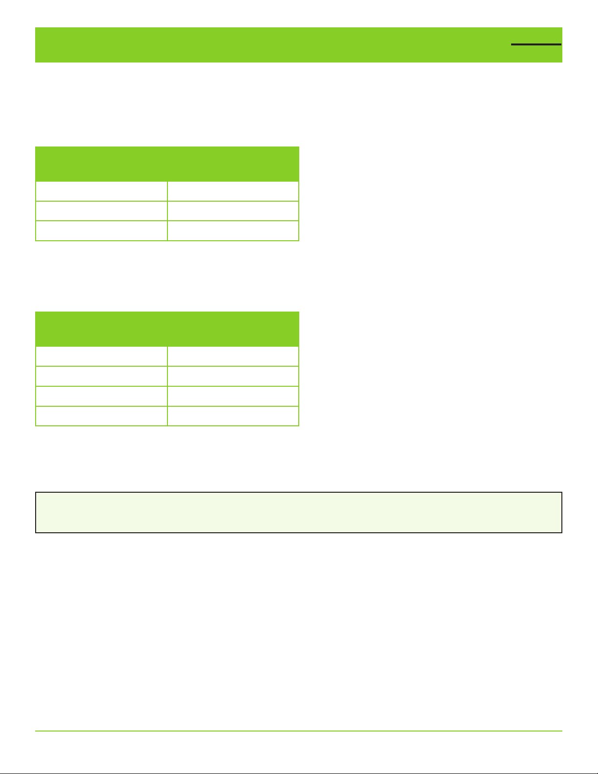
Para mantener una presión constante y evitar la puesta en marcha frecuente, en el sistema se necesita un tanque de
presión de poca capacidad (consulte en la tabla a continuación la capacidad mínima del tanque de presión). El panel
de control VARIOspeed® 3R Dúplex puede usar tanques de presión de mayor capacidad que los listados en la siguiente
tabla.
Capacidad mínima del tanque de presión
Caudal (GPM)
Tamaño del tanque
(Capacidad total)
Menos de 12,0 4 galones
Más de 12,0 8 galones
Más de 50,0 14 galones
Presión de precarga
1. La presión de carga inicial debe ajustarse como mínimo al 70% de la presión del sistema (Presión configurada).
2. Para mantener el control óptimo de la presión, verifique periódicamente la presión en el tanque.
Presión congurada
(PSI)
Presión de
carga inicial (PSI)
50 (por defecto) 35
55 39
60 42
65 46
Es necesario instalar una válvula de alivio de presión.
La válvula de alivio de presión DEBE ir instalada lo más cerca posible de la descarga de la bomba y conectada a un
drenaje que pueda aceptar todo el caudal de la bomba en caso de mal funcionamiento.
¡ADVERTENCIA!
Si no se está utilizando una válvula de alivio de presión y se presentaran fallos en el sistema, podrían reventarse las
tuberías y producir inundaciones.
10 VARIOspeed® 3R Dúplex - Manual del usuario
Page 27
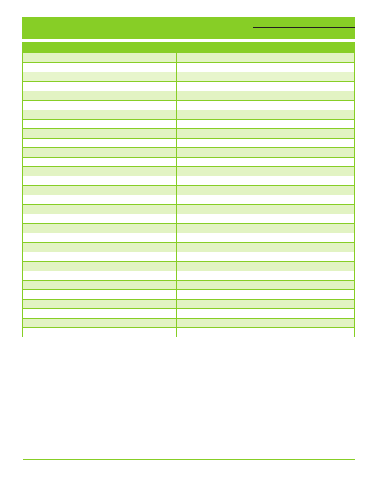
Fallos, alarmas y códigos de advertencia
MENSAJE EN LA PANTALLA PRINCIPAL DESCRIPCIÓN DE LA ALARMA DE FALLO
COMMS LOST (P1/P2) Se ha perdido la comunicación
SENSOR FAILURE Fallo en el sensor de presión
HIGH PRESS WARNING
RUN DRY WARNING Advertencia por funcionamiento en seco (Reinicio automático)
RUN DRY FAULT
SHUTDOWN INPUT Activada la entrada para apagado externo del sistema
OL ACCEL (P1/P2)
OVER CURR (P1/P2)
OL DECEL (P1/P2)
OVER VOLT 1 (P1/P2) E.OV1 - Sobretensión regenerativa
OVER VOLT 2 (P1/P2) E.OV2 - Sobretensión regenerativa
OVER VOLT 3 (P1/P2) E.OV3 - Disparo por sobretensión regenerativa
VFD OL TRIP (P1/P2) E.THT - Disparo por sobrecarga del inversor
MOTOR OL TRIP (P1/P2) E.THM - Disparo por sobrecarga del motor
VFD OVERHEAT (P1/P2) E.FIN - Recalentamiento de la aleta
STALL PREVENTION (P1/P2) E.OLT - Prevención de bloqueo
GROUND FLT (P1/P2) E.GF - Tierra en el lado de salida
OUTPUT PHASE LOSS (P1/P2)
INRUSH CURR LIMIT (P1/P2)
ANALOG INPUT (P1/P2) E.AIE - Fallo en la entrada analógica
INPUT PHASE LOSS (P1/P2)
BRAKE XSTR ALARM (P1/P2) E.BE - Detección de la alarma del transistor de ruptura
XTRNL THERM (P1/P2) E.OHT - Operación del relé/contactor térmico externo
XTRNL THERMIST (P1/P2) E.PTC - Operación del termistor PTC
VFD EEPROM FAULT (P1/P2)
DISCONNECTED PU (P1/P2) E.PUE - Desconexión de la unidad de parámetros PU
FLT RETRY EXCEED (P1/P2) E.RET - Exceso de conteos de reintento
VFD CPU FAULT (P1/P2) E.5/E.CPU - Fallo de la CPU
OUTPUT AMPS DET (P1/P2)
SAFETY CIRC FLT (P1/P2) E.SAF - Fallo en el circuito de seguridad
Advertencia de que hay presión alta
Fallo por func. en seco (es necesario reiniciar manualmente)
E.OC1 - Disparo por sobreintensidad durante la aceleración
E.OC2 - Disparo por sobreintensidad durante veloc. constante
E.OC3 - Disparo por sobreintensidad durante desaceleración
E.LF - Pérdida de fase de salida
E.IOH - Circuito para limitar las súbitas corrientes de entrada
E.ILF - Pérdida de fase de entrada
E.PE - Fallo del dispositivo de almacenamiento de parámetros
E.CDO - Excedido valor de detección de la corriente de salida
IMPORTANTE:
Para reiniciar los fallos, en el VFD pulse la tecla STOP/RESET (Detener / Reiniciar). Cuando se vaya a reiniciar cualquier
fallo, el selector manual/apagado/auto (HAND/OFF/AUTO) debe estar en la posición “OFF”. En caso de no poder
reiniciar un fallo desconectando la alimentación al VFD y conectando nuevamente después de un minuto, por favor
comuníquese con su distribuidor.
®
VARIOspeed
3R Dúplex - Manual del usuario 11
Page 28
Visualizar registros
Visualización del tiempo de operación del motor de la bomba
Pump Motor Run Time
Pump 1 1234567 hours
Pump 2 1234567 hours
Para visualizar el tiempo acumulado de operación del motor, acceder la pantalla "View Run Time" (Visualizar tiempo de
operación) en el menú de configuración. El tiempo de operación se despliega en horas totales de funcionamiento.
Visualizar la historia de fallos del VFD
VFD OVERLOAD TRIP
STALL PREVENTION
VFD OVERLOAD TRIP
VFD OVERLOAD TRIP
Para visualizar la historia de fallos de cada VFD, acceder a la pantalla "VFD1/VFD2 Fault History" (Historia de fallos
de VFD1 / VFD2) en el menú de configuración. Se podrán visualizar los últimos ocho fallos de cada VFD, en orden del
más reciente al más antiguo, desplazándose por la pantalla "Fault History". Si hay un fallo activo en ese momento,
aparecerá de modo intermitente en la pantalla principal.
Tiempo de operación del motor de la bomba
Bomba 1 1234567 horas
Bomba 2 1234567 horas
Disparo por sobretensión en el VFD
Prevenir bloqueo
Disparo por sobretensión en el VFD
Disparo por sobretensión en el VFD
Visualizar el registro de fallos del sistema
-- Time Since Fault -HPress 42d 16:23:42
RunDry No Faults
Para visualizar el registro de fallos del sistema, acceder la pantalla "View Sys Fault Log" (Ver registro de fallos del
sistema) en el menú de configuración. El registro de fallos del sistema muestra el tiempo transcurrido desde que
se presentó una de estas situaciones: PRESIÓN ALTA, FUNCIONAMIENTO EN SECO, ENTRADA PARA APAGADO DEL
SISTEMA, FALLO DEL SENSOR DE LA BOMBA 1 o BOMBA 2. Al ir girando el dial, el usuario puede visualizar todo el
registro de fallos del sistema (System Fault Log). Si no han sucedido fallos, en la pantalla aparece el mensaje “No
Faults”, indicativo de que no ha habido fallos.
ShdnIn No Faults
-- Tiempo transcurrido desde el fallo --
Presión alta
42d 16:23:42
Func. en seco Sin fallos
Entrada, apagado sistema
Sin fallos
12 VARIOspeed® 3R Dúplex - Manual del usuario
Page 29
Conexiones de terminales
208/240 VCA
CORRIENTE DE ENTRADA
MONOFÁSICA
L1
L2
NFC
1
2 3
DB1
208/240V-PANELES MONOFÁSICOS
3
4
CB105
DISYUNTOR
2
1
208/240 VCA
CORRIENTE DE ENTRADA
TRIFÁSICA
L1
L2 L3
1
2 3
DB1
324
1
CB105.1
DISYUNTOR
DEL SISTEMA
ROJO
TRANSDUCTOR
DE PRESIÓN
200 PSI
ENTRADA,
APAGADO
NEGRO
1
2
CB105.2
DISYUNTOR
4
3
TS136 FAN136
VENTILADOR
TERMOSTATO
TB2
3
RUN MON_PRM
RUN
MODE
VARIADOR D700
VFD112
RUN
VARIADOR D700
VFD129
PU_EXT NET
STOP
RESET
SET
RUN MON_PRM
PU_EXT NET
STOP
RESET
SETMODE
PU
EXT
STF
RUN
PU
EXT
STF
RUN
W
V
U
PU
RH
SD
RL
SO
BOMBA 1, OPERACIÓN
TB2
W
V
U
PU
RH
SD
RL
SO
BOMBA 2, OPERACIÓN
2
1
BOMBA 1
TRIFÁSICA
A/1.29
BOMBA 1
LT120
G
HOA
2324
XOO
1314
OOX
BOMBA 2
HOA
2324
XOO
1314
OOX
6
MTR112
5
BOMBA 2
4
208/240 VCA
TRIFÁSICA
B/1.29
LT138
G
1
2
3
4
5
6
7
8
9
10
B/1.32
A/1.14
TB1
TB1
3
4
1
2
ENTRADA+
ENTRADA-
AISLADOR
DE BUCLE
SALIDA+
SALIDA-
T/L3
S/L2
R/L1
G
SE
RM
SD
5
PC
4
VARIADOR DE FRECUENCIA (VFD)
T/L3
S/L2
R/L1
G
SE
RM
SD
5
PC
4
VARIADOR DE FRECUENCIA (VFD)
208/240V-PANELES TRIFÁSICOS
31 5
CB105
DISYUNTOR
642
642
CB105.1
ROJO
TRANSDUCTOR
DE PRESIÓN
200 PSI
3
ENTRADA,
APAGADO
DEL SISTEMA
NEGRO
TB1
TB1
3
4
1
2
CB105.2
DISYUNTORDISYUNTOR
ENTRADA+
ENTRADA-
AISLADOR
DE BUCLE
SALIDA+
SALIDA-
RUN MON_PRM
T/L3
S/L2
R/L1
G
SE
RM
SD
5
PC
4
VARIADOR DE FRECUENCIA (VFD)
T/L3
S/L2
R/L1
G
SE
RM
SD
5
PC
4
VARIADOR DE FRECUENCIA (VFD)
RUN
MODE
VARIADOR D700
VFD112
RUN
VARIADOR D700
VFD129
PU_EXT NET
STOP
RESET
SET
RUN MON_PRM
PU_EXT NET
STOP
RESET
SETMODE
W
V
PU
EXT
U
PU
RH
STF
SD
RL
SO
RUN
W
V
PU
EXT
U
PU
RH
STF
SD
RL
SO
RUN
TB2
3
2
BOMBA 1
1
A/1.29
LT120
G
BOMBA 1, OPERACIÓN
TB2
6
MTR112
5
BOMBA 2
4
B/1.29
LT138
G
BOMBA 2, OPERACIÓN
208/240 VCA
TRIFÁSICA
208/240 VCA
TRIFÁSICA
TS110
TERMOSTATO
BOMBA 1
O
H
BOMBA 2
HOA
VENTILADOR
A
2324
1314
2324
1314
FAN110
XOO
OOX
XOO
OOX
1
2
3
4
5
6
7
8
9
10
B/1.32
A/1.14
142
31 5
VARIOspeed® 3R Dúplex - Manual del usuario 13
Page 30
Conexiones de terminales
VARIADOR DE FRECUENCIA (VFD)
BOMBA 1
480 VCA
CORRIENTE DE ENTRADA
TRIFÁSICA
L1 L2 L3
2 31
DB1
PORTAFUSIBLE
PORTAFUSIBLE
DEL SISTEMA
ROJO
TRANSDUCTOR
DE PRESIÓN
200 PSI
ENTRADA,
APAGADO
NEGRO
TB1
3
4
TB1
1
2
ENTRADA+
ENTRADA-
AISLADOR
DE BUCLE
SALIDA+
SALIDA-
FU105
1 A
FUSIBLE CLASE CC
T/L3
S/L2
R/L1
VARIADOR D700
G
SE
RM
SD
5
PC
4
VARIADOR DE FRECUENCIA (VFD)
T/L3
S/L2
R/L1
VARIADOR D700
G
SE
RM
SD
5
PC
4
VFD112
VFD129
FU103
1 A
FUSIBLE CLASE CC
FU107
XF
6/10 A, 250 V
FUSIBLE MINIATURA
RUN MON_PRM
W
PU_EXT NET
STOP
V
RUN
RESET
PU
SETMODE
EXT
U
PU
RH
STF
SD
RL
SO
RUN
RUN MON_PRM
W
PU_EXT NET
STOP
V
RUN
RESET
PU
SETMODE
EXT
U
PU
RH
STF
SD
RL
SO
RUN
115V
TB2
3
2
BOMBA 1
1
A/1.29
LT120
G
BOMBA 1, OPERACIÓN
TB2
6
MTR112
5
BOMBA 2
4
B/1.29
LT138
G
H2H3
208/240 VCA
H1H4
X2X1
TIERRA
208/240 VCA
TRIFÁSICA
TRIFÁSICA
460V
T105
TS109 FAN109
VENTILADOR
TERMOSTATO
BOMBA 1
O
A
H
XOO
2324
OOX
1314
BOMBA 2
HOA
XOO
2324
OOX
1314
480V-PANELES TRIFÁSICOS
1
2
3
4
5
6
7
8
9
10
B/1.32
A/1.14
14 VARIOspeed® 3R Dúplex - Manual del usuario
Page 31
Instalación
Ventilación
Variador de frecuencia
Termostato
(VFD)
Ventilador
Disyuntores de las
bombas
Disyuntor
del control
del ventilador
Conducto del
transductor
de presión
Conducto
del cable
del motor
Terminales
de tierra
Conducto
de entrada
de corriente
VARIOspeed® 3R Dúplex - Manual del usuario 15
Page 32

Notas: ________________________________________________________________________________
______________________________________________________________________________________
______________________________________________________________________________________
______________________________________________________________________________________
______________________________________________________________________________________
______________________________________________________________________________________
______________________________________________________________________________________
______________________________________________________________________________________
______________________________________________________________________________________
______________________________________________________________________________________
______________________________________________________________________________________
______________________________________________________________________________________
______________________________________________________________________________________
______________________________________________________________________________________
______________________________________________________________________________________
______________________________________________________________________________________
______________________________________________________________________________________
______________________________________________________________________________________
______________________________________________________________________________________
______________________________________________________________________________________
______________________________________________________________________________________
+ 1-800-746-6287
www.sjerhombus.com
Technical Support Hours: Monday - Friday 7 A.M. to 6 P.M. Central Time
16 VARIOspeed
© 2019 SJE, Inc. All Rights Reserved.
SJE RHOMBUS is a trademark of SJE, Inc.
®
3R Dúplex - Manual del usuario
PN 1051668B 12/19
 Loading...