

Page 1
Operating Instructions
Thank you for purchasing this ‘SWALLOW AC/DC EQ CHARGER’ charger. We are sure
you will be pleased with its performance and features. In order to ensure that you obtain
the maximum from its operation, please read the following instructions carefully.
SJ INCORPORATED
Page 2

Input voltage is 11~15V DC, or AC 100V ~ 240V / 50 ~ 60Hz
Capable of charging and discharging 1 - 14 NiCd or NiMH cells, 1 - 6 Lithium-Ion,
Lithium-Polymer or LiFePO4 cells or 2 ~ 12V lead-acid batteries
Adjustable charge current (0.1A - 6.0A)
Adjustable discharge current (0.1A - 1.0A). Auto limited to maintain 5W maximum.
"Zero Delta V" peak detection for NiCd and NiMH batteries
"Constant Current / Constant Voltage" charge method for Lithium-Ion/Po, LiFe batteries
and Pb batteries.
Pack Cycling( Charge to Discharge / Discharge to Charge )
2 -line, 16 character, blue backlit, LCD makes the screen extremely clear and legible.
Built-in an intelligent balancing circuit is designed to individually balance each cell on
the connected lithium battery pack within the tolerance of 5mV during charge or
discharge.
Voltage monitoring feature is to show each actual cell voltage on the screen during
balancing.
Various warning messages for improper input voltage, wrong connections, unsuitable
battery condition and reverse polarity on output.
Packaged in a rugged, extruded aluminum case
*
*
*
*
*
*
*
*
*
*
*
*
2
Operating Instructions
Special Features
Do NOT attempt to charge incompatible types of rechargeable batteries. This charger is
designed to only charge and discharge Nickel-Cadmium, Nickel-Metal Hydride,
Lithium-Ion ,Lithium-Polymer, LiFePO4, and Lead-Acid batteries.
Make sure to place the charger on a firm level surface for charging.
Do not attempt to charge batteries at excessive fast charge currents. Check with your
battery manufacturer for the maximum charge rate applicable to your battery.
Do not use automotive type battery chargers to power the charger.
Do not leave the charger unattended while charging. Disconnect the battery and remove
input power from charger immediately if the charger becomes hot. Allow the charger or
battery to cool down before reconnecting.
Do not allow water, moisture or foreign objects into the charger.
Do not place the battery or charger on or near a flammable object while in use. Keep
away from carpets, cluttered workbenches, etc.
Do not cover the air intake holes on the charger as this could cause the charger to overheat.
Connect the input leads to a 12V power supply first, then connect the battery.
Do not disassemble the charger.
This appliance is not intended for use by young children or infirm persons unless they
have been adequately supervised by a responsible person to ensure that they can use the
appliance safely.
Young children should be supervised to ensure that they do not play with the appliance.
Do not attempt to charge non-rechargeable batteries.
The battery must be placed in a well ventilated area
when charging Lead Acid batteries.
When charging a battery in a vehicle, the battery terminal not connected to the chassis
has to be connected first. The other connection is to be made to the chassis, remote from
the battery and fuel line. The battery charger is then to be connected to the supply mains;
After charging disconnect the battery charger from the supply mains. Then remove the
chassis connection and then the battery connection.
*
*
*
*
*
*
*
*
*
*
*
*
*
*
*
*
Safety precautions
!
Page 3
3
2.SPECIFICATION
Input Voltage
Battery Type & Cells
Battery capacity
Charge Current
Discharge Current
Trickle Charge Current
11.0-15.0V DC, AC 100V ~ 240V / 50 ~ 60Hz
0.1A ~ 6A in 100mA steps(auto limited to 50W maximum)
0.1A ~ 1A in 10mA steps (auto limited to 5W maximum)
0 ~ 200mA
Balancing current Max. 280mA
Delta Peak Sensitivity 5mV ~ 25mV for NiCd & 3mV ~ 25mV for NiMH batteries per cell
Cycling Charge to Discharge / Discharge to Charge
Display Type
Dimensions
2-line, 16 blue backlit character LCD
100mAh ~ 6000mAh adjustable ONLY for Lithium-Ion,
Lithium-Polymer and LiFePO4
Charge Termination
" zero delta V" peak detection for NiCd/NiMH
" constant current / constant voltage " for Li-Ion/Po/Fe and Pb
1-14 Nickel-Cadmium cells / 1-14 Nickel-Metal Hydride cells
1-6 Lithium-Ion or Lithium-Polymer or LiFePO4 cells
( type : 3.6V or 3.7V or 3.3V )
1 - 6 Lead-Acid cells ( 2V per cell )
159 x 152 x 68 mm
Weight 650g
Operating Instructions
1. Set contents
Page 4
4
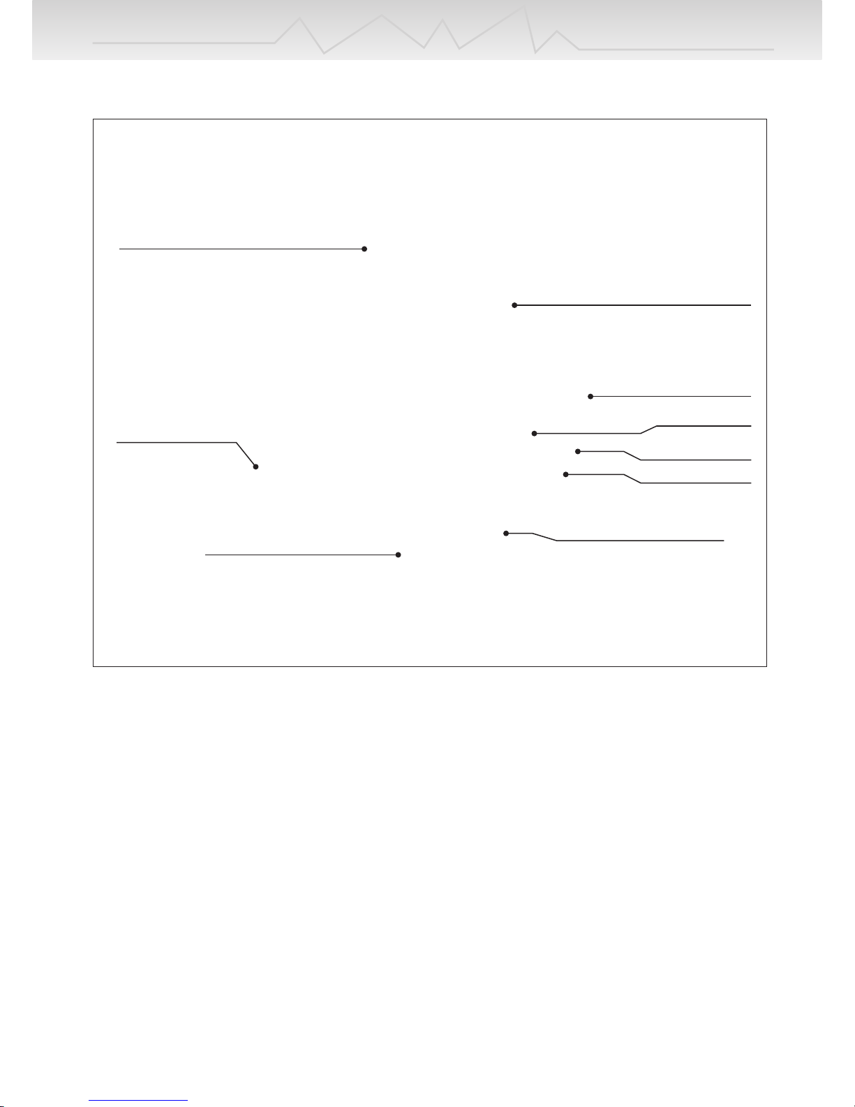
A. Connect the charger to the 12V DC power supply.
Connect the charger’s red alligator clip to the positive (+) terminal on the power source and
the black alligator clip to the negative (-) terminal. The charger will display “Input voltage”
error message if the input is below 11V or above 15V. If this happens, please recheck the
input power supply to make sure adequate power is present.
- OR -
B. Connect the AC plug to a regular AC100~240V wall outlet.
Note : If AC power is being used for input power, do NOT try to connect the 12V DC power as
well !
Operating Instructions
3.CONTROLS
- Input power -
DC 12V
Input alligator clips.
Balancing port
button
+ Output
- Output
Blue backlit display
AC INPUT
Balancing cable
Balancing adapter board
Page 5

5
Operating Instructions
When the charger is connected to the power supply the charger will show the battery mode
that has been last used.
If the battery TYPE button is briefly pressed, the present battery type (NiCd, NiMH,
Lithium, or Pb ) will blink.
While the existing battery type is blinking, every time the battery TYPE button is pressed,
the following modes are shown in order. NiCd NiMH Lithum Pb NiCd
If the other buttons are pressed, or nothing is pressed, the present battery type stops blinking.
If the Battery type button is pressed and briefly held, the recent & previous data will be
shown for 3 seconds.
If the Enter button is briefly pressed, a parameter which can be adjusted starts to blink and
if the Enter button is pressed again, the next parameter starts to blink. If nothing is pressed
for 3 seconds, the parameter stops blinking.
Once the Enter button is pressed and briefly held, the charger starts to charge or discharge
according to the selected parameters.
- Operation -
Two 4mm banana sockets are located on the right side of the charger. Connect the battery
charge lead to these sockets with the positive (+) lead connected to the red socket and the
negative (-) lead to the black socket. The “No battery“ error message will be displayed if
trying to start to charge without connecting a battery. The “Open circuit” error message
will be displayed if a battery becomes disconnected from the charger while a function is in
progress. A “Reverse polarity” error message will be displayed if a battery is connected to
the charger in reverse.
Note.
In order to balance lithium batteries during charge or discharge, pls ensure that both battery
charge leads and balancing connector on the battery pack should be connected to both two
4mm output banana sockets and balancing port together on the charger.
If the battery charge leads are ONLY connected to the output banana sockets without connecting the balancing connector on the lithium battery pack at the balancing port on the charger,
the charger should charge or discharge the connected lithium pack without balancing the pack.
- Output battery connections -
Page 6
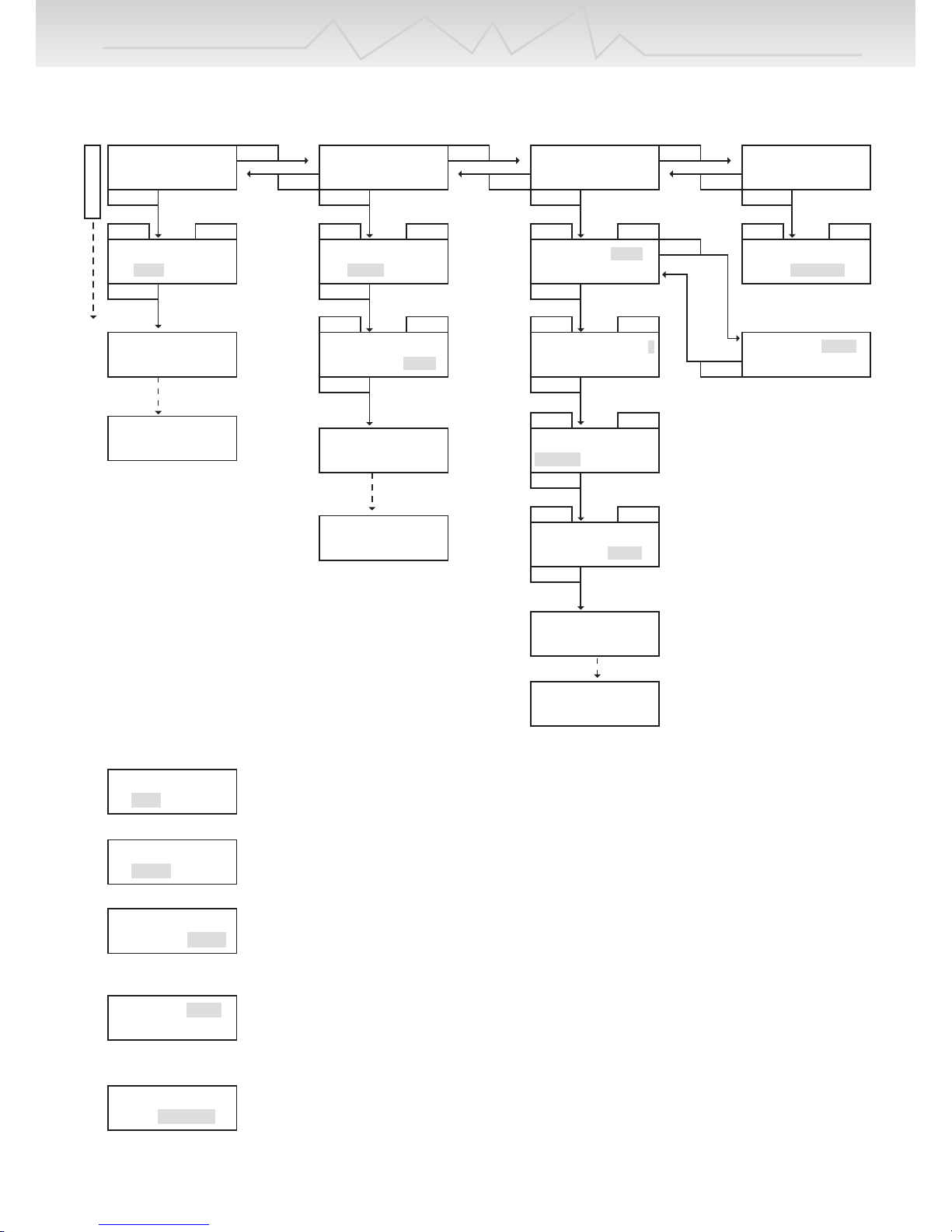
NiCd CYCLE C->D 5
C=3.0A D=0.50A
NiCd DISCHARGE
D=0.50A 4.8 V
6
Operating Instructions
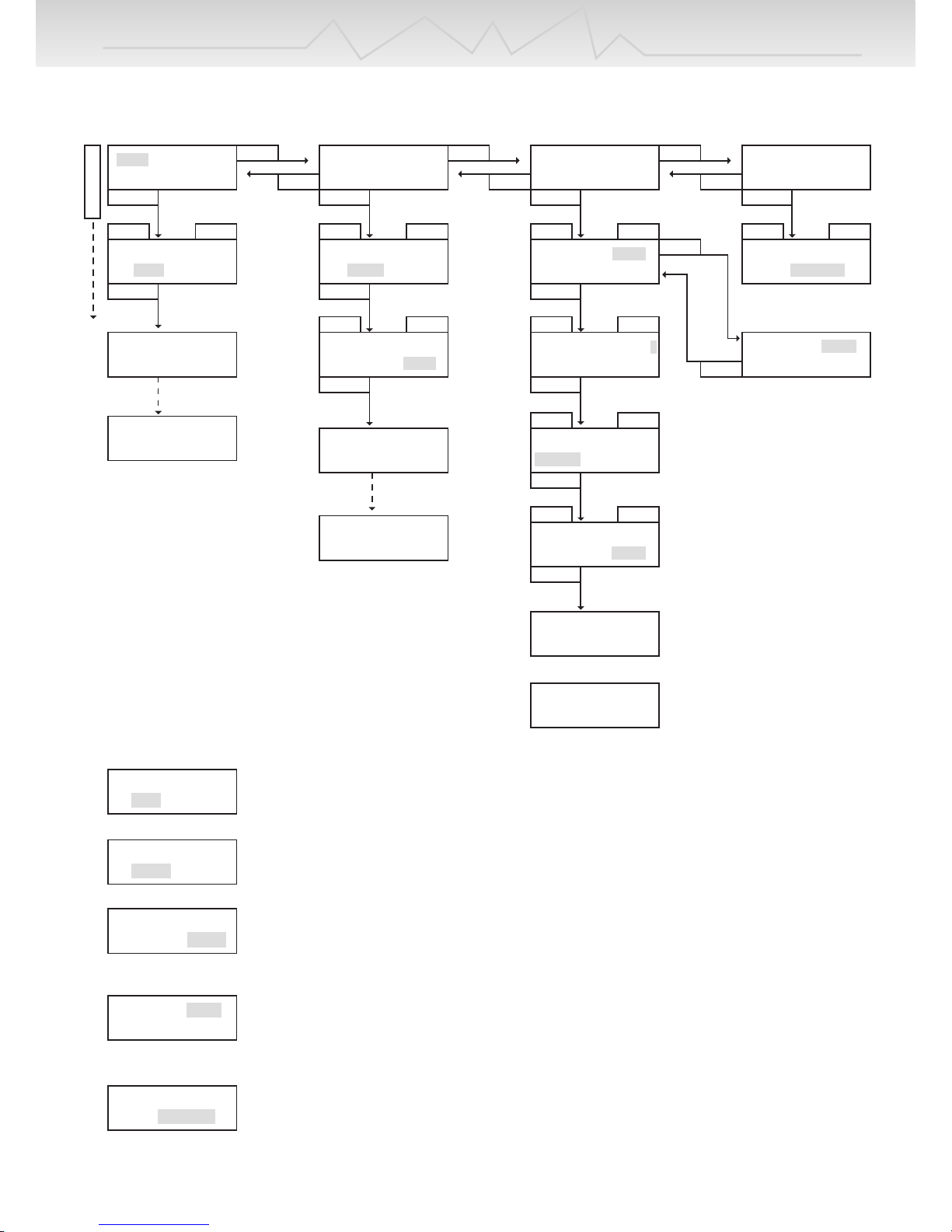
NiCd CHARGE
C=3.0A
Setting charge current
Adjust and find the desired charge current which ranges from 0.1A to 6.0A with the
INC & DEC buttons. Press the ENTER button to confirm the setting.
NiCd DISCHARGE
D=0.50A 4.8 V
Setting discharge current
Adjust and find the desired discharge current which ranges from 0.1A to 1A with the
INC & DEC buttons. Press the ENTER button to confirm the setting.
Setting discharge cutoff voltage
This is the voltage that the charger should stop discharging the battery.
Adjust and find total discharge cutoff voltages to be discharged from 0.1V to 16.8V
with the INC & DEC buttons. Press the ENTER button to confirm the setting.
Setting cycle
This is to set cycling with two options (Charge to Discharge / Discharge to Charge).
Set cycling with the INC & DEC buttons and press the ENTER button to confirm the
setting.
NiCd delta-peak'volt = 0mV/cell
Setting Delta Peak Sensitivity.
This is to set the Delta Peak Sensitivity from 5mV to 25mV per cell with INC & DEC
buttons and press the ENTER button to confirm the setting.
NiCd CYCLE D->C 5
C=3.0A D=0.50A
NiCd CYCLE D->C 5
C=3.0A D=0.50A
NiCd CYCLE D->C 5
C=3.0A D=0.50A
4. NiCd MODE
NiCd CHARGE
C=3.0A
NiCd DISCHARGE
D=0.50A 4.8 V
NiCd CYCLE D->C 5
C=3.0A D=0.50A
NiCd delta-peak'volt = 0mV/cell
INC
DEC
INC DECINC DECINC DECINC DEC
ENTER ENTER
ENTER ENTER
ENTER
ENTER
START
ENTER ENTER
INC
DEC
INC
DEC
INC
DEC
NiCd CHARGE
C=3.0A
NiCd DISCHARGE
D=0.50A 4.8 V
NiCd CYCLE D->C 5
C=3.0A D=0.50A
NiCd delta-peak'volt = 0mV/cell
START
START
INC DECINC DEC
BATTERY CHECK
WAIT PLEASE. . . .
NiCd DISCHARGE
D=0.50A 4.8 V
NiCd CYCLE C->D 5
C=3.0A D=0.50A
INC DEC
CHG 0:00 00000
NC + 3.00A 1.200V
BATTERY CHECK
WAIT PLEASE. . . .
INC DEC
DCH 0:00 00000
NC - 0.50A 5.200V
BATTERY CHECK
WAIT PLEASE. . . .
D->C 0:00 00000
NC - 0.50A 5.200V
BATT TYPE
Page 7
7
Operating Instructions
NiMH CYCLE D->C 5
C=3.0A D=0.50A
NiMH CYCLE D->C 5
C=3.0A D=0.50A
NiMH CYCLE D->C 5
C=3.0A D=0.50A
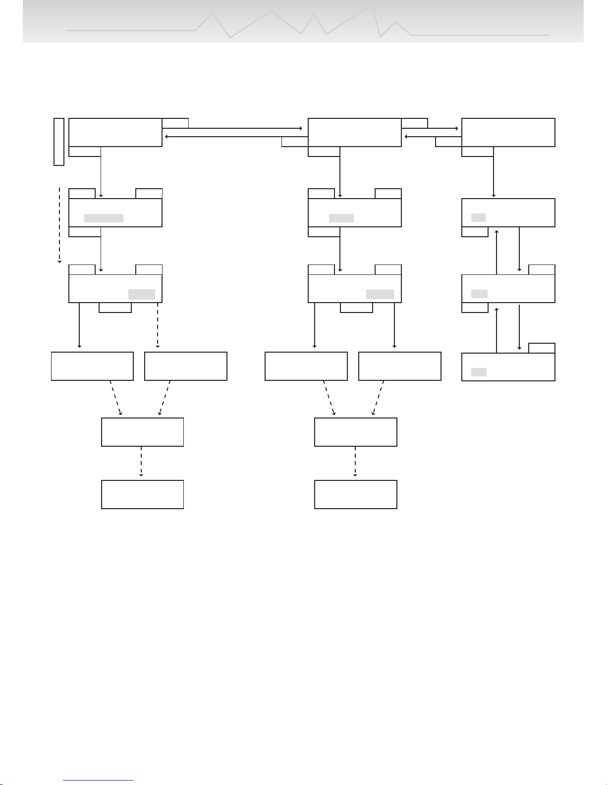
5. NiMH MODE
NiMH CHARGE
C=3.0A
NiMH DISCHARGE
D=0.50A 4.8 V
NiMH CYCLE D->C 5
C=3.0A D=0.50A
NiMH delta-peak'volt = 0mV/cell
INC
DEC
INC DECINC DECINC DECINC DEC
ENTER ENTER
ENTER SETUP
SETUP
SETUP
START
SETUP ENTER
INC
DEC
INC
DEC
INC
DEC
NiMH CHARGE
C=3.0A
NiMH DISCHARGE
D=0.50A 4.8 V
NiMH CYCLE D->C 5
C=3.0A D=0.50A
NiMH delta-peak'volt = 0mV/cell
START
START
INC DECINC DEC
BATTERY CHECK
WAIT PLEASE. . . .
NiMH DISCHARGE
D=0.50A 4.8 V
NiMH CYCLE C->D 5
C=3.0A D=0.50A
INC DEC
CHG 0:00 00000
NH + 3.00A 1.200V
BATTERY CHECK
WAIT PLEASE. . . .
INC DEC
DCH 0:00 00000
NH - 0.50A 5.200V
BATTERY CHECK
WAIT PLEASE. . . .
D->C 0:00 00000
NH - 0.50A 5.200V
BATT TYPE
NiMH CYCLE C->D 5
C=3.0A D=0.50A
NiMH DISCHARGE
D=0.50A 4.8 V
NiMH CHARGE
C=3.0A
Setting charge current
Adjust and find the desired charge current which ranges from 0.1A to 6.0A with the
INC & DEC buttons. Press the ENTER button to confirm the setting.
NiMH DISCHARGE
D=0.50A 4.8 V
Setting discharge current
Adjust and find the desired discharge current which ranges from 0.1A to 1A with the
INC & DEC buttons. Press the ENTER button to confirm the setting.
Setting discharge cutoff voltage
This is the voltage that the charger should stop discharging the battery.
Adjust and find total discharge cutoff voltages to be discharged from 0.1V to 16.8V
with the INC & DEC buttons. Press the ENTER button to confirm the setting.
Setting cycle
This is to set cycling with two options ( Charge to Discharge / Discharge to Charge).
Set cycling with the INC & DEC buttons, and press the ENTER button to confirm the
setting.
NiMH delta-peak'volt = 0mV/cell
Setting Delta Peak Sensitivity.
This is to set the Delta Peak Sensitivity from 3mV to 25mV per cell with INC & DEC
buttons and press the ENTER button to confirm the setting.
Page 8
BATTERY CHECK
WAIT PLEASE. . . .
CHG 0:00 00000
LI + 3.00A 11.800V
BALANCER CON.
NOT CONNECTED
BALANCER CON.
CONNECTED
BALANCER CON.
NOT CONNECTED
BALANCER CON.
CONNECTED
8
Operating Instructions
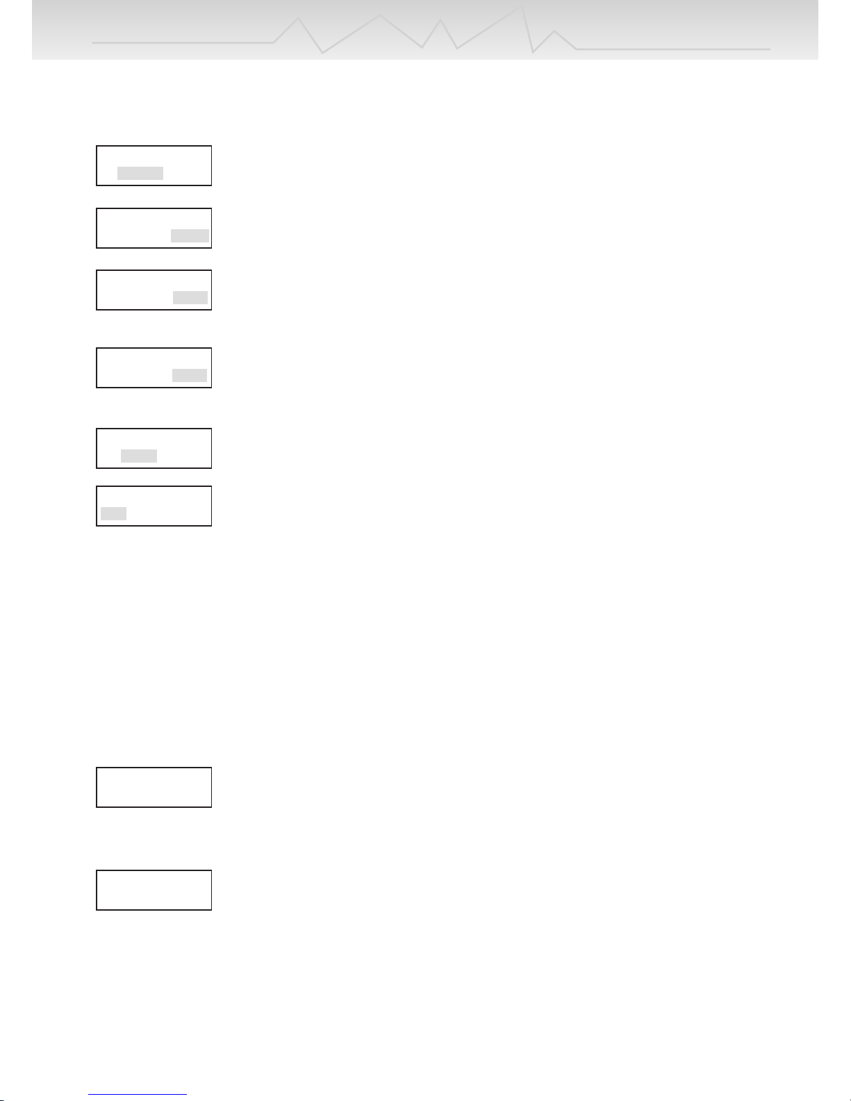
6. Lithium MODE ( Li-Ion / LiPo / LiFe )
LiIo CHARGE
C=3000mAh 10.8Vp
LiIo DISCHARGE
D=0.50 A 10.8Vp
Lithium type
LiIo
LiIo CHARGE
C=3000mAh 10.8Vp
LiIo DISCHARGE
D=0.50A 10.8Vp
Lithium type
LiIo
LiIo CHARGE
C=3000mAh 10.8Vp
LiIo DISCHARGE
D=0.50A 10.8Vp
Lithium type
LiPo
Lithium type
LiFe
BATTERY CHECK
WAIT PLEASE. . . .
DCH 0:00 00000
LI - 0.50A 9.800V
BATT TYPE
INC DEC INC DEC
INC DEC INC INC
INC
DEC
DEC
DEC
START START
ENTER ENTER
ENTER
ENTER
ENTER
DEC
INC
DEC
INC
This charger is capable of charging Lithium-Ion, Lithium-Polymer and LiFePO4 batteries up to 6 cells. This
charger uses “constant current / constant voltage“ in order to fully charge those lithium batteries. Constant
current is delivered during the fast charge. When the voltage of the Li-Ion, Li-Po battery and LiFePO4 reaches
approx 4.1V, 4.2V, and 3.7V per cell, the charger starts to change its charge method from “constant current” to
“constant voltage “. The “constant voltage“ allows the battery to dictate how much current the charger should
deliver for safe, full charges. When the current drops below approx 1/10 currents of user selected battery capacity, the charger will stop charging as the battery is fully charged.
Page 9
9
Operating Instructions
LiFe CHARGE
C=3000mAh 11.1Vp
LiPo CHARGE
C=3000mAh 11.1Vp
LiIo CHARGE
C=3000mAh 10.8Vp
Setting battery capacity
Adjust and set the desired battery capacity from 100mAh to 6000mAh
(50mAh per step) with the INC & DEC buttons. Press the ENTER button to confirm the setting.
LiIo CHARGE
C=3000mAh 10.8Vp
Setting battery voltages for Li-Ion battery pack
Select the proper total battery voltages to be charged or discharged with the INC & DEC buttons
– 3.6V, 7.2V, 10.8V, 14.4V, 18.0V and 21.6V [Vpack]
Setting battery voltages for Li-Po battery pack
Select the correct total battery voltages to be charged or discharged with the INC & DEC
buttons – 3.7V, 7.4V, 11.1V, 14.8V, 18.5V and 22.2V [Vpack]
Setting battery voltages for Li-Fe battery pack
Select the correct total battery voltages to be charged or discharged with the INC & DEC
buttons – 3.3V, 6.6V, 9.9V, 13.2V, 16.5V and 19.8V [Vpack]
LiIo DISCHARGE
D=0.50 A 10.8Vp
Setting discharge current
Adjust and find the desired discharge current from 0.10A to 1.00A (0.01A per step) with the INC
& DEC buttons. Press the ENTER button to confirm the setting.
Lithium type
LiPo
Setting battery type
Choose the desired battery type (Li-Ion, Li-Po or Li-Fe ) with the INC & DEC buttons. Press the
ENTER button to confirm the setting.
BALANCER CON.
NOT CONNECTED
The left screen should be shown if lithium charge or discharge starts without connecting the
balancing cable to the balancing port of the charger.
BALANCER CON.
CONNECTED
The left screen should be shown if lithium charge or discharge starts with connecting the
balancing cable to the balancing port of the charger.
For safety purposes, this charger is designed to automatically deliver a 1C charge rate to batteries of
Li-Ion, Li-Po or Li-Fe, based on the user selected battery capacity.
Example: Li-Po cell of 1500mAh capacity : 1C = 1500mAh ( = 1.5A ) charge current.
Note : The maximum voltage for Li-Ion is 4.1V per cell, 4.2V per cell for Li-Po batteries, and
3.7V per cell for Li-Fe batteries. Therefore, it is extremely important to choose the proper
battery type to be charged, as each Lithium battery has the different voltage level. Otherwise,
it may cause very serious damage to the batteries and increase the risk of a fire !
Page 10
Pb DISCHARGE
D=0.50A 12Vpack
Pb CHARGE
C=3.0A 12Vpack
Pb CHARGE
C=3.0A 12Vpack
Pb CHARGE
C=3.0A 12Vpack
Pb CHARGE
C=3.0A 12Vpack
Pb DISCHARGE
D=0.50A 12Vpack
10
Operating Instructions
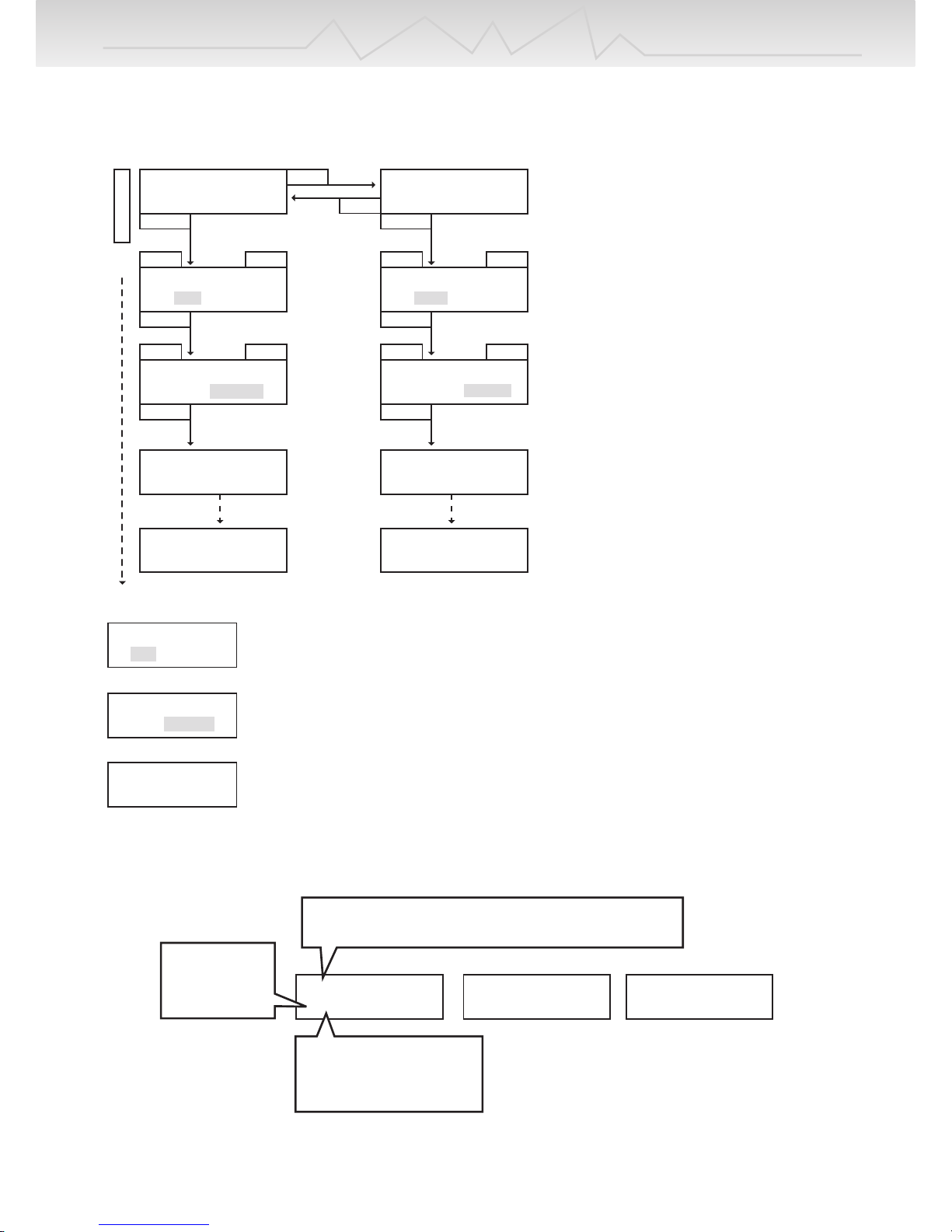
7. Pb MODE
Pb CHARGE
C=3.0A 12Vpack
Pb DISCHARGE
D=0.50A 12Vpack
Pb DISCHARGE
D=0.50A 12Vpack
BATT TYPE
INC DEC INC DEC
INC DEC INC DEC
START
ENTER
ENTER ENTER
ENTER
START
BATTERY CHECK
WAIT PLEASE. . . .
BATTERY CHECK
WAIT PLEASE. . . .
CHG 0:00 00000
Pb + 3.00A 12.800V
CHG 0:00 00000
Pb - 0.50A 11.200V
DEC
INC
to NiCd charge
Setting charge current
Adjust and find the desired charge current which ranges from 0.1A to 6.0A with the INC & DEC
buttons. Press the ENTER button to confirm the setting
Setting battery voltages for Li-Ion battery pack
Select the proper total battery voltages to be charged or discharged with the INC & DEC buttons
– 2V, 4V, 6V, 8V, 10V, and 12V [Vpack]
Setting discharge current
Adjust and find the desired discharge current from 0.10A to 1.00A (0.01A per step) with the INC
& DEC buttons. Press the ENTER button to confirm the setting.
8. Displays during charge, discharge, and cycle
If the Enter button is pressed, the charge or discharge can be terminated.
CHG 030:25 00000
NC + 3.00A 10 .75V
DCH 030:25 00000
NC - 3.00A 10 .75V
D->C 0:00 00000
NH + 3.0 1.200
“BLC” should be shown if the balancer cable is connected
to the balancing port of the charger.
CHG: charge
DCH: discharge
C→D: cycle
D→C: cycle
NC: NiCd
NM: NiMH
LI: LiIo , LP: LiPo , LF: LiFe
Pb: Pb
Page 11
LCB-[01]= 0.000V
LCB-AVG = 0.000V
LCB-MAX= 0.000V
LCB-MIN = 0.000V
11
Operating Instructions
END 030:00 00000
NC 100mA 10.75V
9. Completion display
10. Data display
11. Error messages
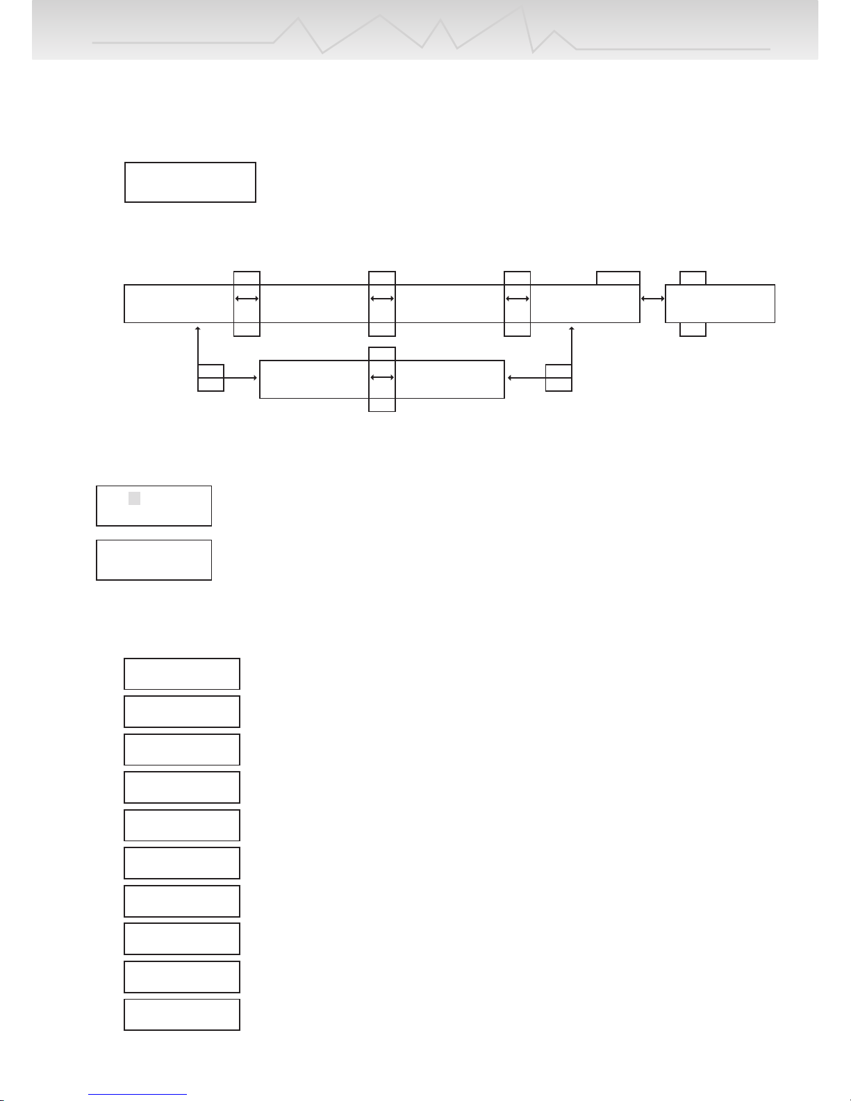
In order to move to the main display, press the Enter button.
INPUT = 12.00V
OUTPUT = 13.18V
ChgCAPA=00000mAh
DchCAPA=00000mAh
CHG PEAK = 12.00V
DCHG AVR = 13.18V
0.00 0.00 0.00V
0.00 0.00 0.00V
LCB-MAX = 0.000V
LCB-MIN = 0.000V
LCB-[01] = 0.000V
LCB-AVG = 0.000V
LCB-[02] = 0.000V
LCB-AVG = 0.000V
INC
INC
DEC
DEC
INC
DEC
INC
DEC
INC
DEC
INC
DEC
ENTER
INC
DEC
If the Battery type button is pressed for over 3 seconds, the Data view will be displayed as above.
Data displays can be scrolled left and right by INC & DEC buttons.
If the Battery type button is again pressed, those data view screen should be disappeared.
This screen is only shown if a balancing connector is connected.
Press the ENTER button then the “01” should flash, each cell voltage is shown by INC & DEC
buttons.
This screen is also only shown if a balancing connector is connected.
Its shows each maximum and minimum voltages on the screen.
INPUT BATTERY
VOLTAGE ERROR
When input voltage is below 11.0V or exceeds 15V.
NO BATTERY
When a battery is not connected to the charger’s output
OUTPUT BATTERY
REVERSE POLARITY
When a battery is connected to the output in reverse
OUTPUT CIRCUIT
PROBLEM
When the circuit of the charger has a problem
CHECK THE BATT.
OPEN CIRCUIT
When a battery becomes disconnected during an operation
CHECK THE BATT.
OVER VOLTAGE
If wrong voltages are set while charging lithium or Pb batteries.
CHECK THE BATT.
LOW VOLTAGE
If wrong voltages are set, or batteries are over discharged, while charging Lithium or Pb
batteries
BALANCER VOLTAGE
IS TOO HIGH
If voltage per cell is too high during balancing, this message should appear.
BALANCER VOLTAGE
IS TOO LOW
If battery cells are short-circuited during balancing, this message should appear.
DONT CHARGE LIXX
WITH THIS MODE
If the charger starts charging, discharging, or cycle for NiCd/MH, or Pb batteries with
connecting the balancing cable to the balancing port of the charger.
Page 12

 Loading...