

Page 1
PROGRAMMABLE HUMIDITY PROBE – PHP01
1/7
PROGRAMMABLE HUMIDITY PROBE – PHP01
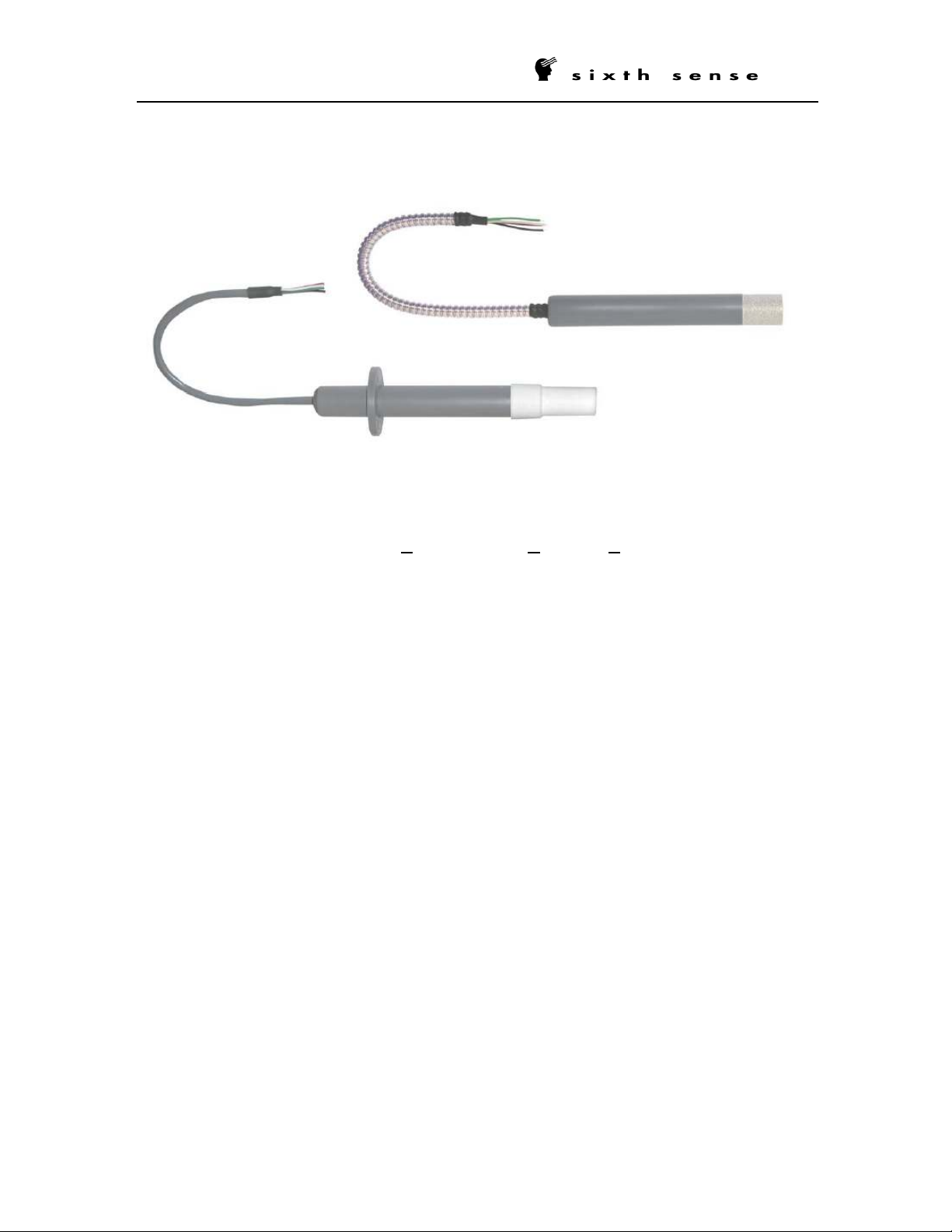
1. Description
The Sixth Sense PHP is a Programmable Humidity Probe designed for the
measurement of relative humidity. Humidity measurement is based on the capacitive thin
film polymer sensor which is located at the tip of the probe and protected by a
membrane filter. The PHP measures the relative humidity and provides a linear 2-wire
(loop) 4-20 mA output signal directly proportional to the 0$100% RH. The PHP uses the
same wires for power and output signal. A third wire is provided for calibration. The PHP
can be re-calibrated with the PHP software and the PHP-Config module provided
separately, P/N PHP01-PKit.
2. Note
Prior to unpacking and installation, please read the operating instructions and follow
them carefully. These units are to be used, serviced, and repaired only by individuals
who are familiar with the operating instructions and the applicable regulations for
operational safety and accident prevention.
3. Control of Units
The units are calibrated and checked before shipment and shipped in good conditions. If
you detect a visible defect on the unit, we recommend that you carefully check the
packing material. In the event of a defect, please immediately notify the mail service /
freight forwarder, as they are responsible for shipping damage.
Page 2

Red = Loop +
Black = Loop -
Blue
Power
3-wire RTD
PROGRAMMABLE HUMIDITY PROBE – PHP01
2/7
4. Dimensions
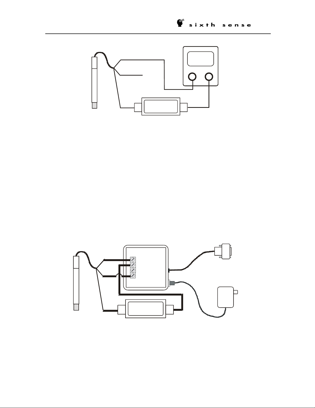
5. Wiring
The PHP can be connected in stand-alone mode for normal operation or in
communication mode for calibration.
Stand-Alone mode:
• Ensure that the power is disconnected before proceeding with the electrical
• Connect the RED wire of the PHP to the positive side of the power supply.
• Connect the BLACK wire of the PHP to the positive side of the current indicator.
• Connect the negative side of the loop indicator to the negative side of the power
• Turn ON the power supply.
Output
4-20 mA Loop
installation.
supply to close the loop.
Red = Loop +
Black = Loop -
White = Rx
4-20 mA Loop Power &
Output
White = Rx
Green
Orange
RTD
Page 3
0
0
+
_
Loop Indicator
Power Supply
+
-
_
V+
V
-
Tx
Rx
PROGRAMMABLE HUMIDITY PROBE – PHP01
Communication mode:
• Ensure that the power is disconnected before proceeding with the electrical
installation.
• Connect the RED wire of the PHP to V+ terminal on the PHP-Config module.
• Connect the BLACK wire of the PHP to the positive side of the current indicator.
• Connect the negative side of the current indicator to V- terminal on the PHP-
Config module.
• Connect the WHITE wire of the PHP to the Rx terminal on the PHP-Config
module.
• Connect the PHP-Config module to the computer via a serial port.
• Power ON the PHP-Config module by connecting first the wall adapter to the
PHP-Config module and then to the 115 VAC.
PHP 01
Red
White
Black
24.0
N.C.
20.
PHP-Config. Module
DB9 - To PC (RS-232)
Red
White
AC Adapter- To 115 VAC
PHP 01
Black
+
2 0 . 0 0
Loop Indicator
3/7
Page 4

_
V+
V
-
Tx
Rx
PROGRAMMABLE HUMIDITY PROBE – PHP01
NOTE: Normally, in the communication mode, the PHP-Config module powers the
PHP but it can also be powered by an external power supply. In this case, the Vterminal on the PHP-Config module needs to be connected to the positive side of
the Loop Indicator and black wire of the PHP probe. The RED wire, from the PHP,
needs to be connected to the positive side of the power supply. The V+ on the
PHP-Config module must not be connected. The negative side of the Loop
Indicator must connect to the negative terminal of the power supply. It is
important to also power the PHP-Config module with the wall adapter for the
communication.
4/7
PHP-Config. Module
DB9 - To PC (RS-232)
White
AC Adapter- To 115 VAC
Loop Indicator
Red
Black
+
2 0 . 0 0
Power Supply
PHP 01
6. Calibration
Calibration and maintenance of the probes should be performed at regular intervals,
depending on the conditions of use and desired accuracy. The recommended calibration
interval is one year.
To proceed with the PHP calibration you first have to connect the probe to the
communication module (please refer to section 5 of this manual). You will then need to
install the PHP software on a computer having a serial port available.
To install the software simply insert the CD in your drive and launch the self-extracting
PHP-CAL program. The PHP-CAL software will be installed by default in the Program
Files\PHP-CAL subdirectory. To launch the PHP-CAL software, simply click on the
shortcut appearing in the Windows menu.
Page 5

PROGRAMMABLE HUMIDITY PROBE – PHP01
In the main window of the PHP-CAL software, select the communication port where the
communication module is connected. If the port selected is not available, a warning
message will appear on the screen. Make sure that the port selected is available and no
other software is using it (ex: Palm Pilot software).
The “ZERO” section of the main window contains the UP and DWN buttons that will be
used to adjust the zero reading. The “SPAN” section contains the UP and DWN buttons
that will be used to adjust the span of the PHP output.
The “Increment” section allows you to select the rate of change of the output signal per
click on the UP and DWN buttons. The coarse increment causes a change of about 0.20
mA (1.25% RH) and the fine increment causes a change of about 0.02 mA (0.125% RH).
5/7
For a better calibration, carefully remove the filter cap from the extremity of the probe.
DO NOT TOUCH THE SENSOR.
1-Point Calibration
The PHP can be calibrated at one point (ex: 50%). To do so, you will require a reference
probe or saturated salt solutions, the PHP connected to the PHP-Config module and the
PHP-CAL software to do the adjustment.
If you are using a reference probe, leave the reference probe and the PHP probe in the
same space for at least an hour so that their temperatures have time to equalize. When
the output from the reference probe and the PHP probe are stabilized, apply the
correction to the PHP output by clicking on the Zero UP or Zero DOWN button in the
PHP-CAL software.
If you are using saturated salt solution, leave the probe in the saturated solution for at
least an hour. When the output signal from the PHP probe is stabilized, apply the
correction to the PHP output by clicking on the Zero UP or Zero DOWN button in the
PHP-CAL software.
Page 6

PROGRAMMABLE HUMIDITY PROBE – PHP01
2-Point Calibration
For a better accuracy along its entire range, the PHP probe can be calibrated at two
different points. To do so, you will require a reference probe or saturated salt solutions,
the PHP connected to the PHP-Config module and the PHP-CAL software to do the
adjustment.
A dry point calibration should be performed first. The dry point needs to be at an RH
below 50% (ideally 30% or lower). Leave the PHP probe at the low RH for at least an
hour to stabilize. Adjust the output of the PHP probe by clicking on the ZERO UP or
ZERO DWN buttons in the PHP-CAL software.
A wet point calibration should then be performed after. The wet point needs to be at an
RH above 50% (ideally 70% or higher). Leave the PHP probe at the high RH for at least
an hour to stabilize. Adjust the output of the PHP probe by clicking on the SPAN UP or
SPAN DWN buttons in the PHP-CAL software.
The PHP probe does not have interaction between the ZERO and SPAN adjustment if
the calibration was performed in the right sequence; zero adjustment first, followed by
the span adjustment. So, it is not necessary to re-do the ZERO adjustment after
changing the SPAN.
6/7
Page 7

PROGRAMMABLE HUMIDITY PROBE – PHP01
7/7
Specifications
Sensing Element: Thermoset polymer thin film capacitive RH sensor
Calibrated Range: 5% to 95% RH
System Accuracy: ±2%, ±3 %, or ±5% RH ( 5% to 95 % RH range )
Supply Voltage: 12-36 VDC, polarity protected
Power Requirement: 40mA max @ 24 VDC
Supply Voltage Effect: ±0.002 RH/volt (negligible) from 12-36 VDC
Output: 4–20 mA, loop powered 2-wire, 0 to 100% RH
4–20 mA, loop powered 2-wire, 0 to 100% RH and 3-wire
RTD.
Repeatability: ±0.5% RH
Linearity: ±1% RH
Hysteresis: ±1% RH of operating humidity span
Sensor Stability: ±1% RH typical at 50% RH in 1 year
Temperature Effect: ±0.03% RH/0 °C ±1% RH at +10 °C to +85 °C (-40°F to
+185 °F)
Temperature Comp.: - 23 °C to +85 °C (-10°F to +185 °F)
Operating Environment: - 40 °C to +85 °C (-40°F to +185 °F) non-condensing (0%
to 95% RH)
Storage Environment: - 50 °C to +85 °C ( -58°F to +185 °F ) non-condensing
Zero and Span Adjust.: Digital recalibration via PHP-Config1 Module and PC
Sensor Break Indication: Upscale to 23mA
Polarity Protection: Diode reverse polarity protected
Sensor Protection: HPDE dust cover 60 micron or sintered SS dust cover 60
micron ( optional )
Sensor Housing: PVC or SS316 ( optional )
Mounting: Flange, 1/ 2” NPT fitting, 3/ 4” NPT fitting
Pressure Ratings: 50 psig for PVC housing and 100 psig for SS housing
Probe Connections: Various extension cables, molded connectors with extension
cable and connector with screws
Protection: Electronics IP67 (NEMA 6X), sensor IP20 and with dust
filter IP50
 Loading...