

Page 1
ASSEMBLY GUIDE
PAVE N ’ TR A IL
SIXTHREEZERO
Page 2

Page 3

We want you to love your bike as much as we do.
If you run into any issues, no matter how small,
let us know and we’ll take care of it.
OUR COMMITMENT
SIXTHREEZERO
THETEAM@SIXTHREEZERO.COM
310.982.2877
Page 4
Need assembly, repair, or installation assistance? He’s your guy!
Want live help? Call or email to schedule an appointment.
MEET JACOB,
OUR MECHANIC
MECHANICS@SIXTHREEZERO.COM
310.982.2877
Page 5

Welcome to the sixthreezero experience. Now for the fun
part... the assembly.
I know, I know, we’ve all had to assemble something we’ve
bought before - a tv stand, coffee table, possibly a grill or
even a bike a time or two before. It ’s never fun, it never goes
well, you always lose a nut or a screw and by the time you’re
done, you’d rather destroy whatever it is you’ve bought
than actually use it. Well, I’m here to make sure that doesn’t
happen.
Assembly of a bike can be a fun, engaging, learning
experience. Call up a friend, ask your spouse or child, don’t
rush, and enjoy the process. Part of the fun in building your
bike is telling people “I built it all by myself.” I build bikes
almost everyday and I always learn something new. I enjoy
the process of building something from the ground up, and
I hope you will too.
The instructions were written and designed by me, so if you
have any suggestions please let me know!
Good luck,
MECHANIC / SIXTHREEZERO
A N OT E F R O M
OUR MECHANIC
Page 6

Creating something wonderful with your own hands is basically the
best feeling ever. We want you to have fun building your new bike,
so there’s only a few things you need to get started.
TOOLS
YOU’LL NEED
Page 7
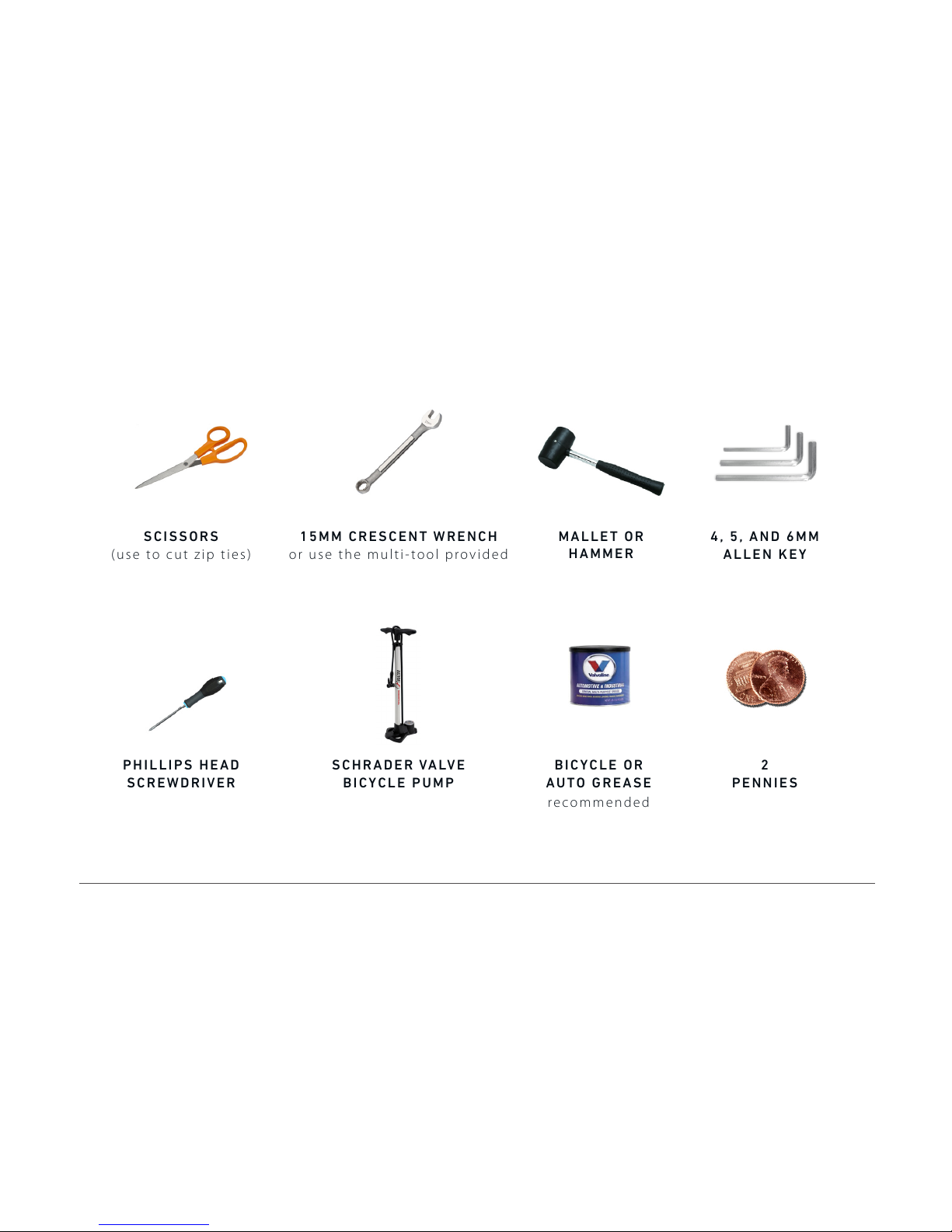
4, 5, AND 6MM
ALLEN KEY
P H IL L IPS H E AD
SCREWDRIVER
SCISSORS
(use to cut zip ties)
15MM CRESCENT WRENCH
or use the multi-tool provided
S C HR A DER VA LV E
BICYCLE PUMP
B I CY C LE O R
AUTO GREASE
2
PENNIES
recommended
M A LL E T OR
HAMMER
Page 8
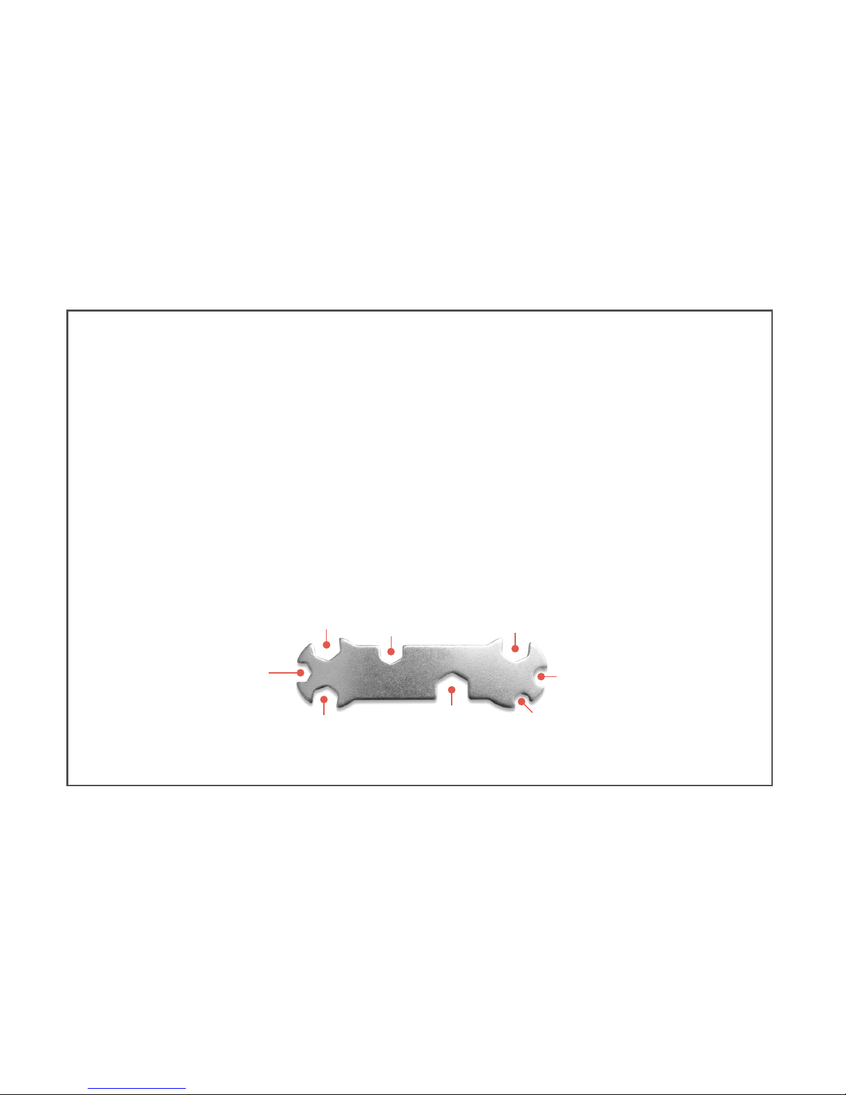
Lay out all the parts in front of you.
Make sure you have all the parts before getting started.
WHAT’S IN
THE BOX?
12MM
14MM
17MM
10MM
8MM
PEDALS + REAR AXEL
15MM
13MM
9MM
Page 9
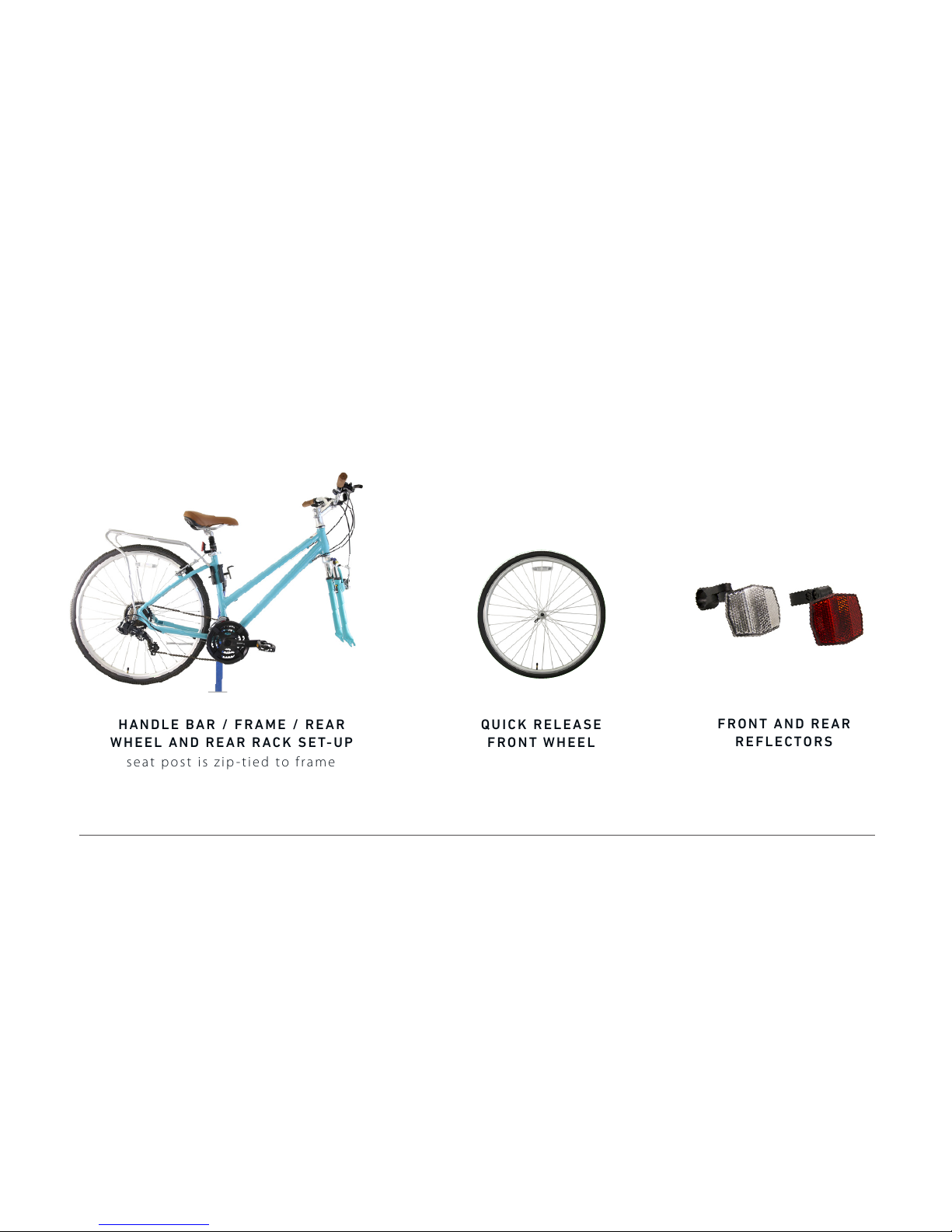
F R ON T A ND R EA R
REFLECTORS
Q U IC K RE LE A SE
FRONT WHEEL
seat post is zip-tied to frame
H A ND L E B A R / F RA M E / RE A R
WHEEL AND REAR RACK SET-UP
BOX 1
Page 10
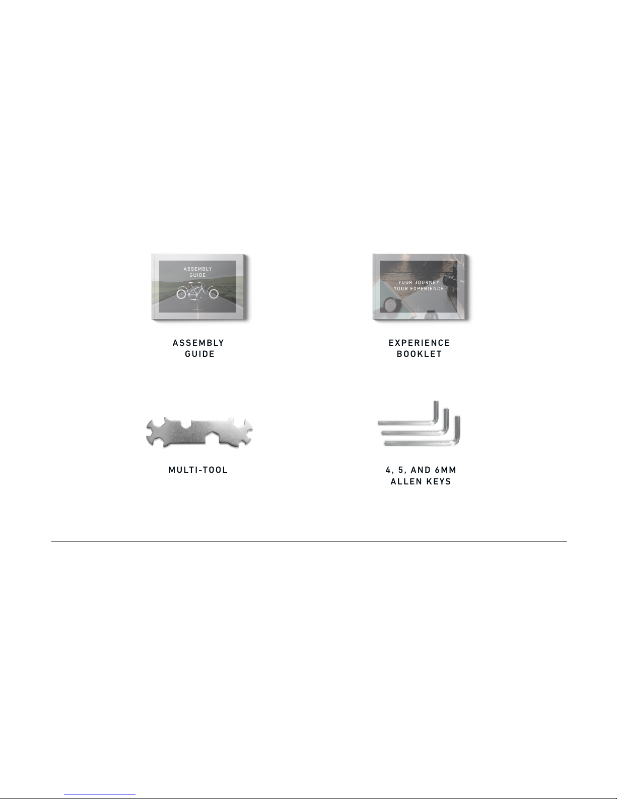
ASSEMBLY
GUIDE
4, 5, AND 6MM
ALLEN KEYS
MULTI-TOOL
E X PE R IEN CE
BOOKLET
BOX 2
Page 11
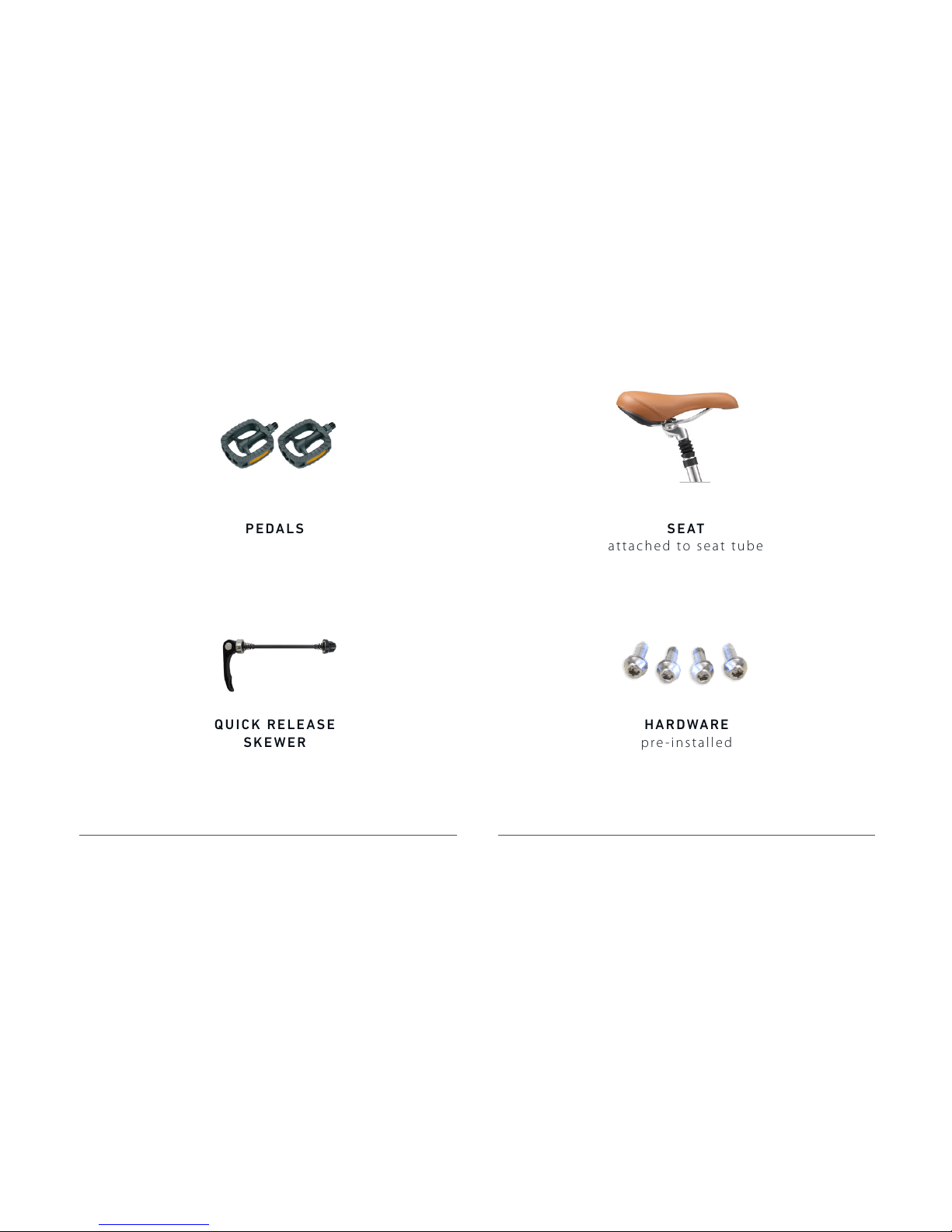
PEDALS
Q U IC K RE LE A SE
SKEWER
SEAT
a t ta ch e d to se at tu be
BOX 3
BOX 4
HARDWARE
pre-installed
Page 12

All the names of all the parts for your bike, all in one place.
Keep this handy during assembly, and everything will go just fine.
BIKE PARTS
REFERENCE GUIDE
Page 13
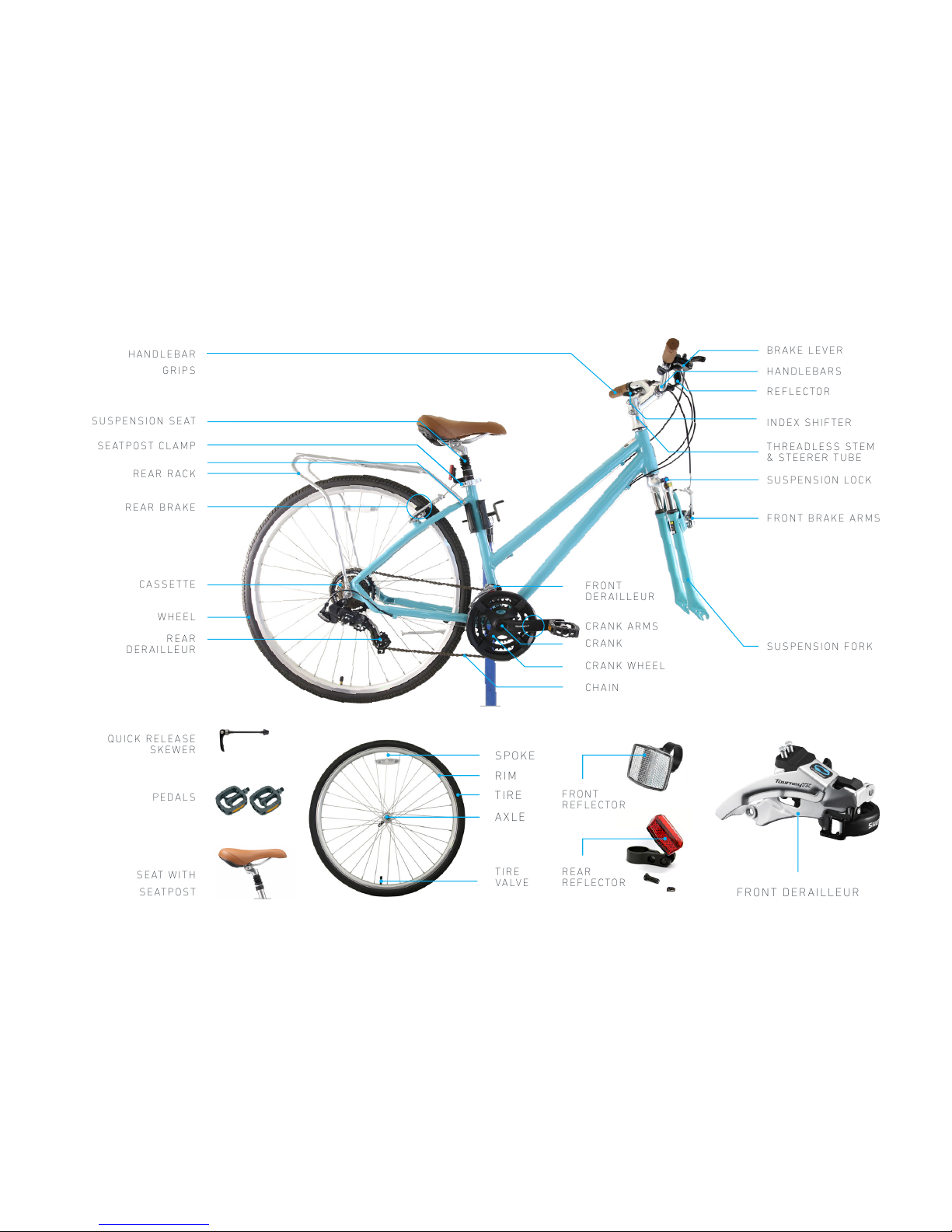
SUSPENSION SEAT
SEATPOST CLAMP
REAR BRAKE
CASSETTE
REAR
DERAILLEUR
WHEEL
REAR RACK
H A N D LE B AR
GRIPS
HANDLEBARS
T H R E AD L ES S S T EM
& STEERER TUBE
BRAKE LEVER
REFLECTOR
INDEX SHIFTER
FRONT BRAKE ARMS
SUSPENSION LOCK
FRONT
DERAILLEUR
CRANK
CHAIN
CRANK WHEEL
CRANK ARMS
SUSPENSION FORK
PEDALS
QUICK RELEASE
SKEWER
S E AT W I TH
SEATPOST
SPOKE
RIM
TIRE
AXLE
FRONT DERAILLEUR
FRONT
REFLECTOR
R E A R
REFLECTOR
T I R E
VALVE
Page 14
HAVING TROUBLE? WANT LIVE HELP? CALL 310.982.2877 OR EMAIL INFO@SIXTHREEZERO.COM.
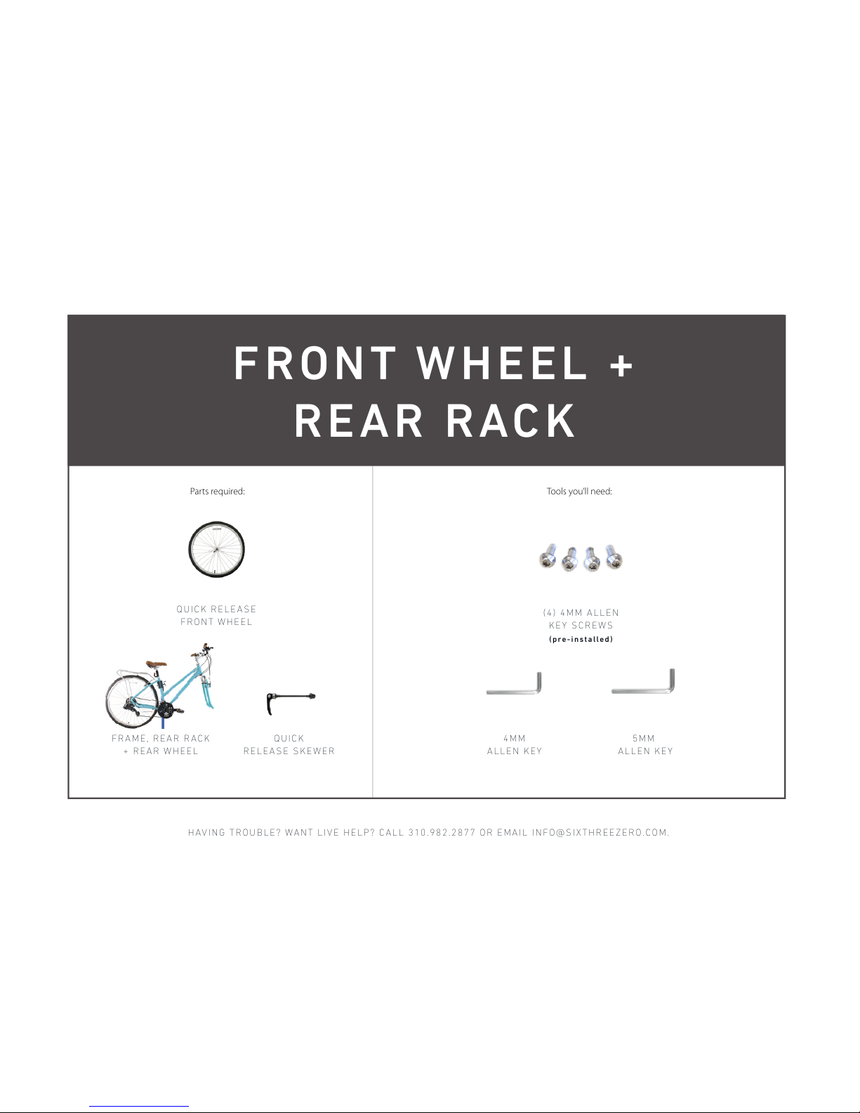
Tools you’ll need:Parts required:
4 M M
ALLEN KEY
QUICK RELEASE
FRONT WHEEL
Q U I C K
RELEASE SKEWER
F R A M E, R EA R R A C K
+ REAR WHEEL
( 4 ) 4M M A LL E N
KEY SCREWS
( pre-installed)
FRONT WHEEL +
REAR R ACK
5MM
ALLEN KEY
Page 15
WATCH ASSE MBLY VIDEOS ON OUR YOUTUB E CHANNEL , HTTPS:/ /SIXTHREE ZERO.COM/ PAGES/ASSEMB LY
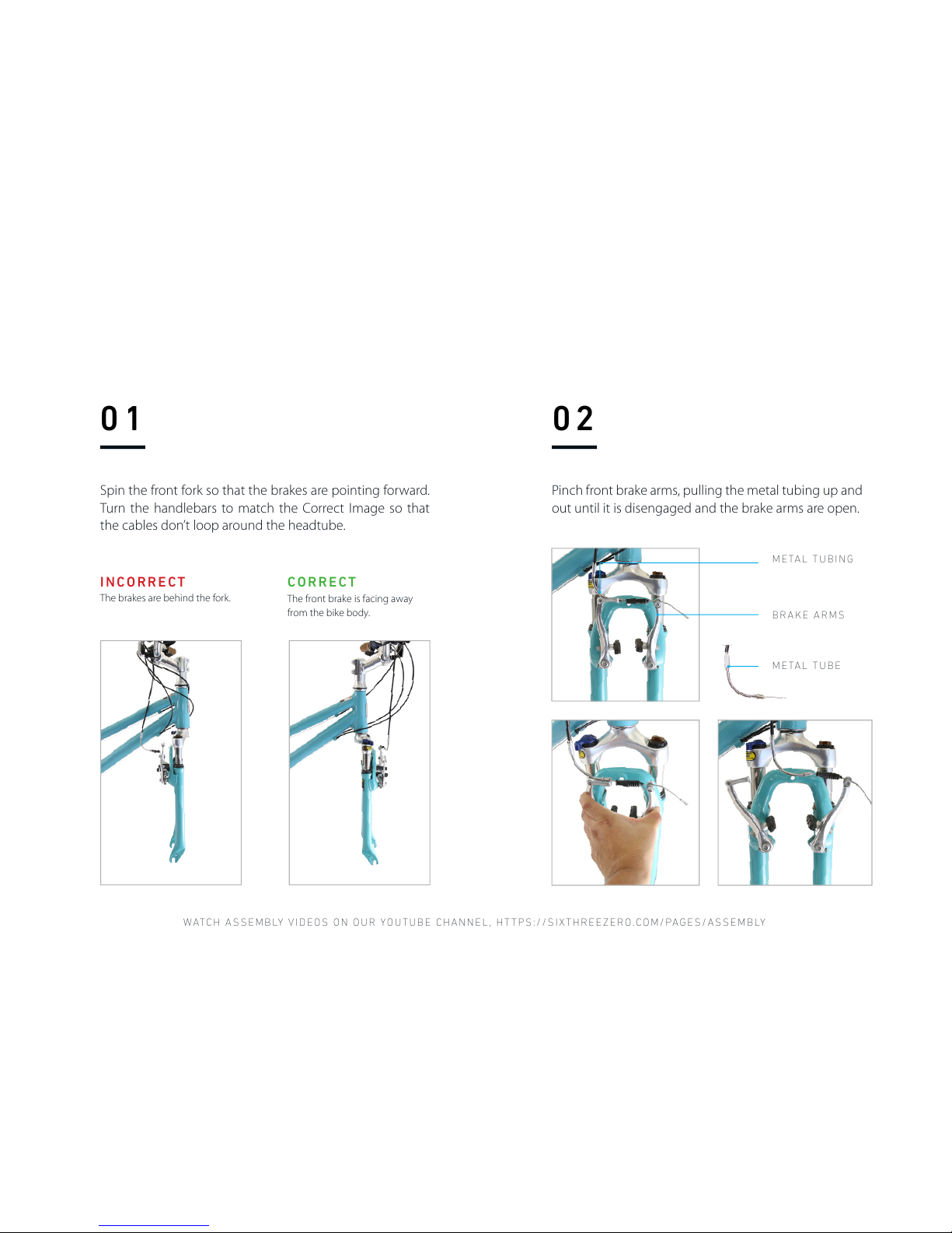
BRAKE ARMS
METAL TUBE
METAL TUBING
The front brake is facing away
from the bike body.
CORRECT
The brakes are behind the fork.
INCORRECT
01
Spin the front fork so that the brakes are pointing forward.
Turn the handlebars to match the Correct Image so that
the cables don’t loop around the headtube.
02
Pinch front brake arms, pulling the metal tubing up and
out until it is disengaged and the brake arms are open.
Page 16
HAVING TROUBLE? WANT LIVE HELP? CALL 310.982.2877 OR EMAIL INFO@SIXTHREEZERO.COM.
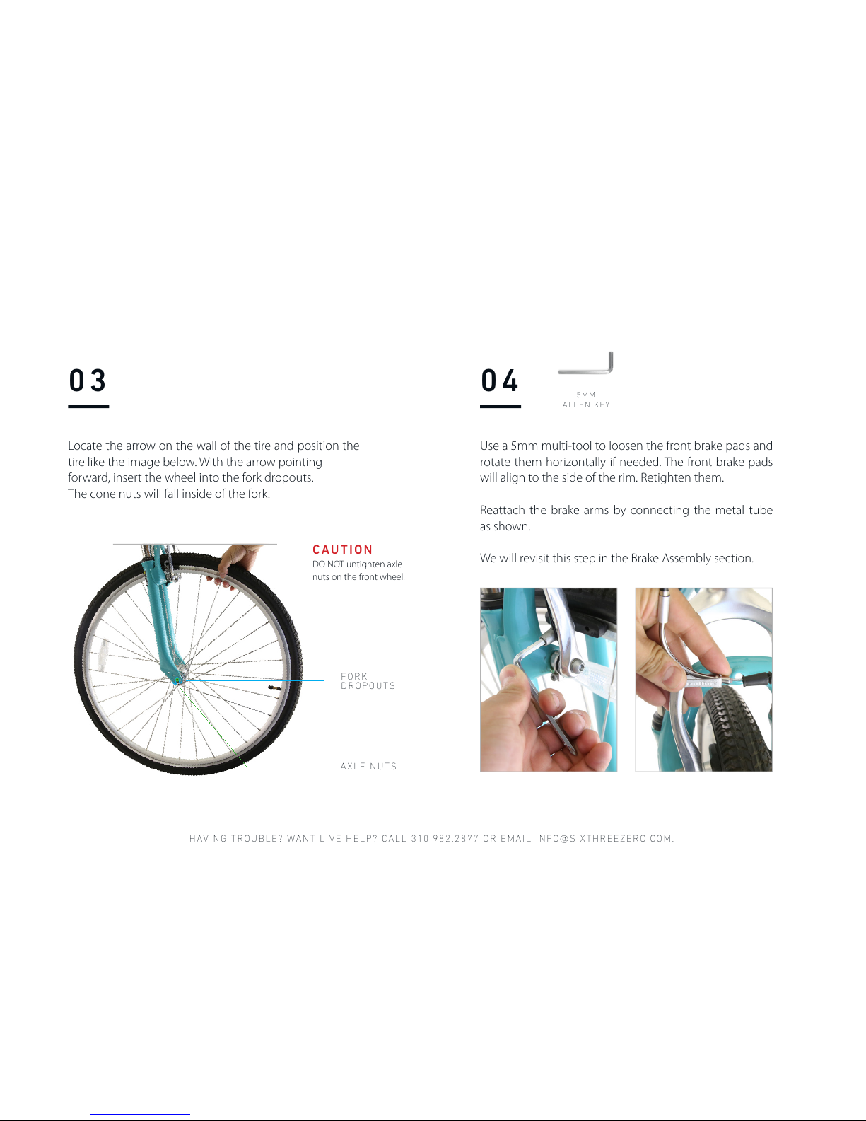
F O R K
DROPOUTS
AXLE NUTS
Locate the arrow on the wall of the tire and position the
tire like the image below. With the arrow pointing
forward, insert the wheel into the fork dropouts.
The cone nuts will fall inside of the fork.
DO NOT untighten axle
nuts on the front wheel.
CAUTION
03 04
Use a 5mm multi-tool to loosen the front brake pads and
rotate them horizontally if needed. The front brake pads
will align to the side of the rim. Retighten them.
Reattach the brake arms by connecting the metal tube
as shown.
We will revisit this step in the Brake Assembly section.
5 M M
ALLEN KEY
Page 17
WATCH ASSE MBLY VIDEOS ON OUR YOUTUB E CHANNEL , HTTPS:/ /SIXTHREE ZERO.COM/ PAGES/ASSEMB LY
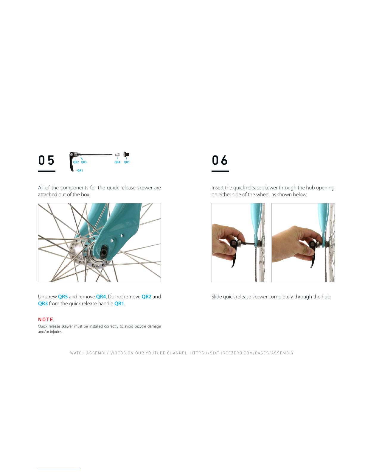
05
All of the components for the quick release skewer are
attached out of the box.
Unscrew QR5 and remove QR4. Do not remove QR2 and
QR3 from the quick release handle QR1.
- QR1
QR4QR2 QR3 QR5
----
----
-
----
Quick release skewer must be installed correctly to avoid bicycle damage
and/or injuries.
NOTE
06
Insert the quick release skewer through the hub opening
on either side of the wheel, as shown below.
Slide quick release skewer completely through the hub.
Page 18
HAVING TROUBLE? WANT LIVE HELP? CALL 310.982.2877 OR EMAIL INFO@SIXTHREEZERO.COM.
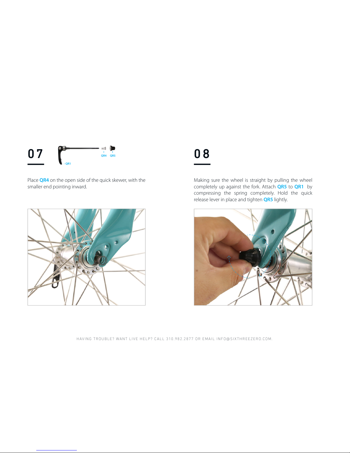
08
Making sure the wheel is straight by pulling the wheel
completely up against the fork. Attach QR5 to QR1 by
compressing the spring completely. Hold the quick
release lever in place and tighten QR5 lightly.
07
Place QR4 on the open side of the quick skewer, with the
smaller end pointing inward.
- QR1
QR4 QR5
----
----
Page 19
WATCH ASSE MBLY VIDEOS ON OUR YOUTUB E CHANNEL , HTTPS:/ /SIXTHREE ZERO.COM/ PAGES/ASSEMB LY
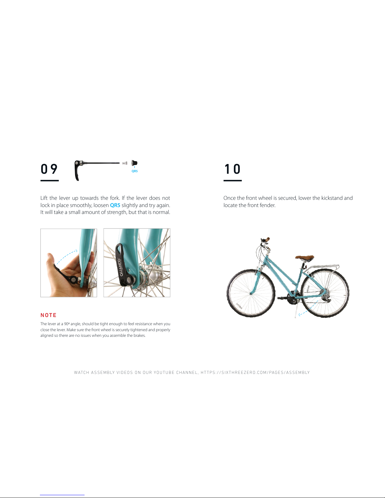
The lever at a 90º angle, should be tight enough to feel resistance when you
close the lever. Make sure the front wheel is securely tightened and properly
aligned so there are no issues when you assemble the brakes.
NOTE
09
Lift the lever up towards the fork. If the lever does not
lock in place smoothly, loosen QR5 slightly and try again.
It will take a small amount of strength, but that is normal.
QR5
----
10
Once the front wheel is secured, lower the kickstand and
locate the front fender.
Page 20
HAVING TROUBLE? WANT LIVE HELP? CALL 310.982.2877 OR EMAIL INFO@SIXTHREEZERO.COM.
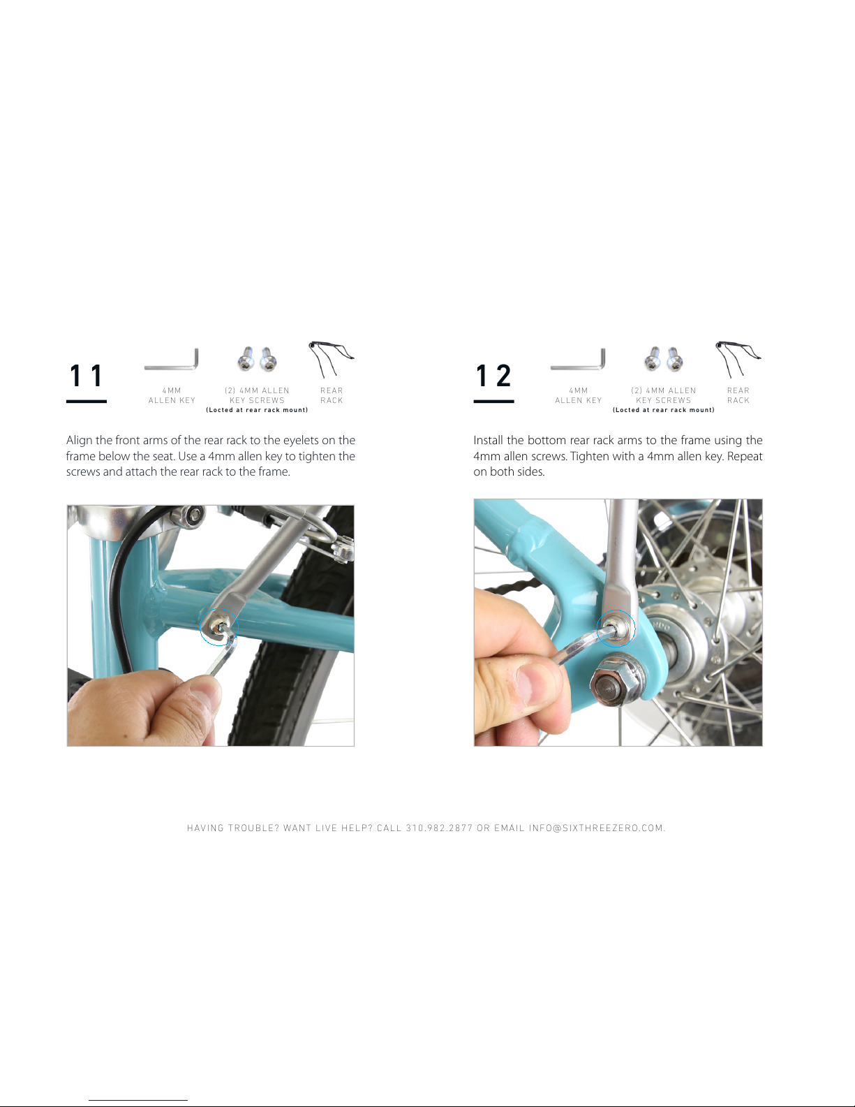
Align the front arms of the rear rack to the eyelets on the
frame below the seat. Use a 4mm allen key to tighten the
screws and attach the rear rack to the frame.
11 12
4 M M
ALLEN KEY
4 M M
ALLEN KEY
REAR
RACK
REAR
RACK
( 2 ) 4M M AL LE N
KEY SCREWS
(Locted at rear rack mount)
( 2 ) 4M M AL LE N
KEY SCREWS
(Locted at rear rack mount)
Install the bottom rear rack arms to the frame using the
4mm allen screws. Tighten with a 4mm allen key. Repeat
on both sides.
Page 21
WATCH ASSE MBLY VIDEOS ON OUR YOUTUB E CHANNEL , HTTPS:/ /SIXTHREE ZERO.COM/ PAGES/ASSEMB LY
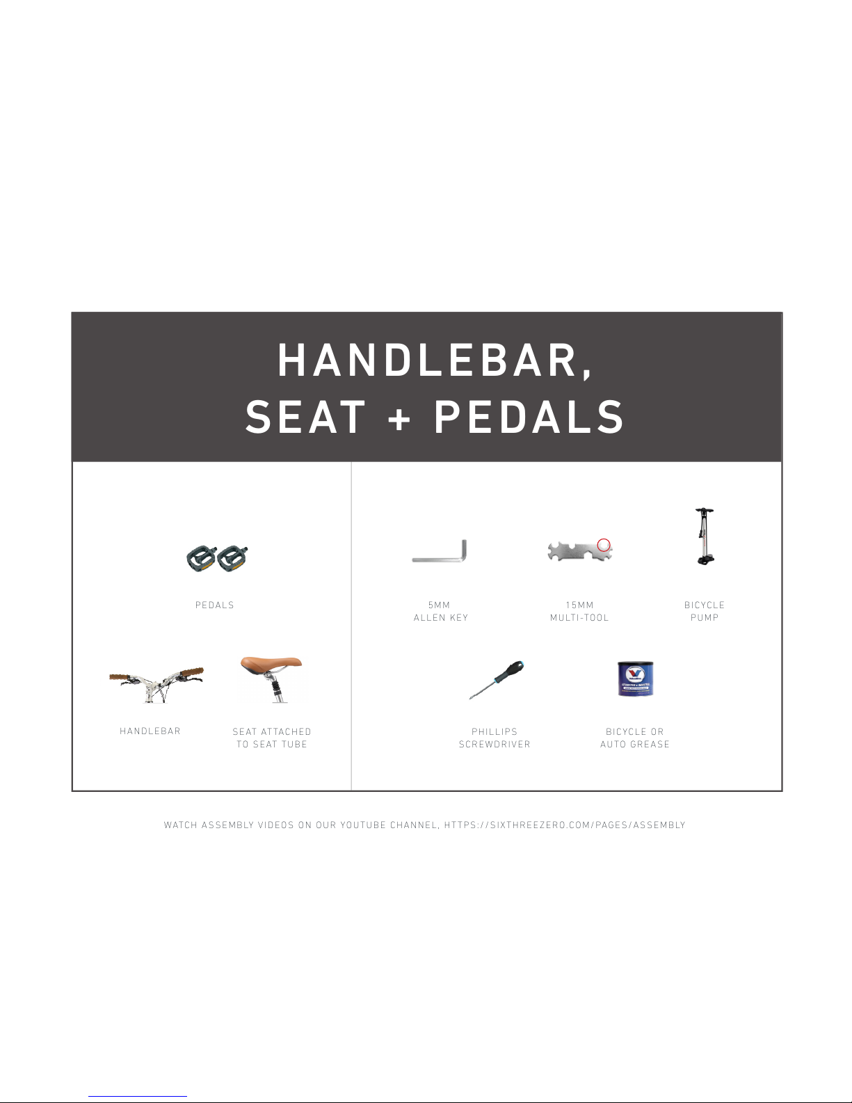
HANDLEBAR,
SEAT + PEDALS
HANDLEBAR
S E AT AT TA C H E D
TO SEAT TU BE
5MM
ALLEN KEY
P H I L LI P S
SCREWDRIVER
15MM
MULTI-TOOL
B I C Y C LE OR
AUTO GREASE
PEDALS B I C Y C LE
PUMP
Page 22
HAVING TROUBLE? WANT LIVE HELP? CALL 310.982.2877 OR EMAIL INFO@SIXTHREEZERO.COM.
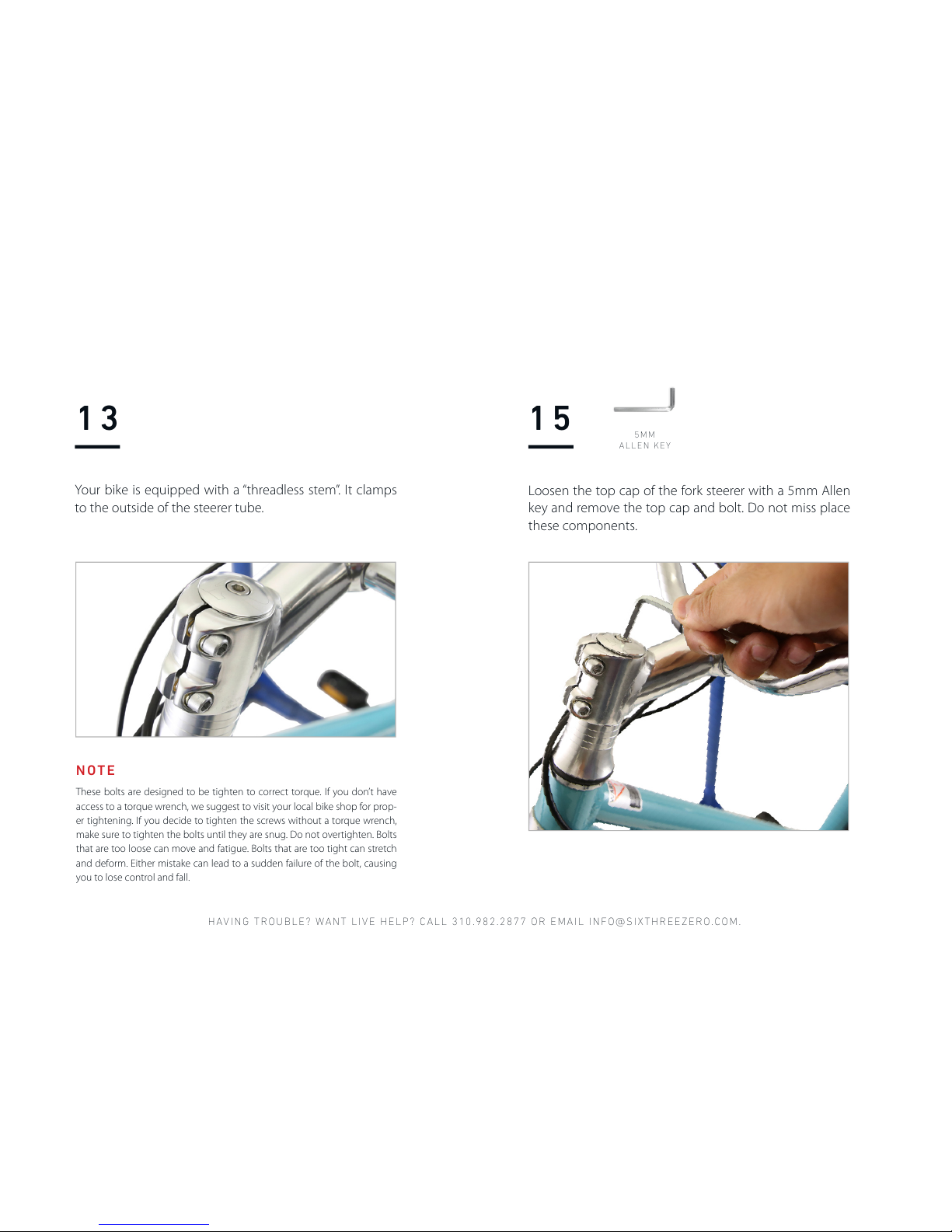
Your bike is equipped with a “threadless stem”. It clamps
to the outside of the steerer tube.
13 15
5 M M
ALLEN KEY
These bolts are designed to be tighten to correct torque. If you don’t have
access to a torque wrench, we suggest to visit your local bike shop for prop-
er tightening. If you decide to tighten the screws without a torque wrench,
make sure to tighten the bolts until they are snug. Do not overtighten. Bolts
that are too loose can move and fatigue. Bolts that are too tight can stretch
and deform. Either mistake can lead to a sudden failure of the bolt, causing
you to lose control and fall.
NOTE
Loosen the top cap of the fork steerer with a 5mm Allen
key and remove the top cap and bolt. Do not miss place
these components.
Page 23
WATCH ASSE MBLY VIDEOS ON OUR YOUTUB E CHANNEL , HTTPS:/ /SIXTHREE ZERO.COM/ PAGES/ASSEMB LY
16
5 M M
ALLEN KEY
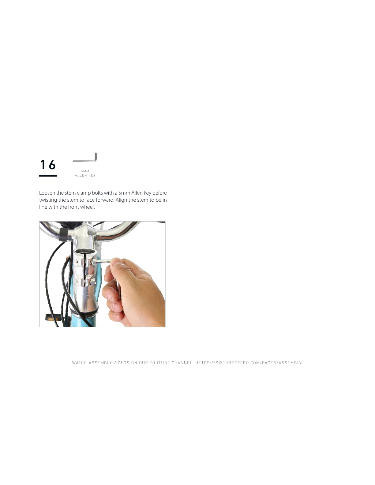
Loosen the stem clamp bolts with a 5mm Allen key before
twisting the stem to face forward. Align the stem to be in
line with the front wheel.
Page 24
HAVING TROUBLE? WANT LIVE HELP? CALL 310.982.2877 OR EMAIL INFO@SIXTHREEZERO.COM.
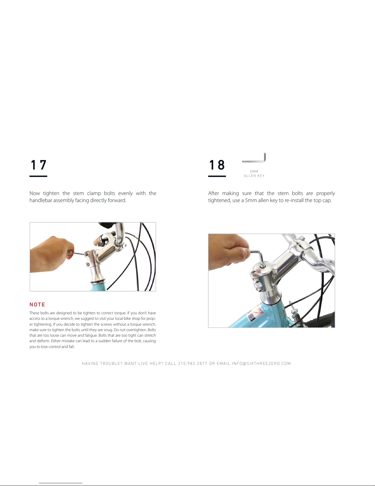
Now tighten the stem clamp bolts evenly with the
handlebar assembly facing directly forward.
17 18
5 M M
ALLEN KEY
After making sure that the stem bolts are properly
tightened, use a 5mm allen key to re-install the top cap.
These bolts are designed to be tighten to correct torque. If you don’t have
access to a torque wrench, we suggest to visit your local bike shop for prop-
er tightening. If you decide to tighten the screws without a torque wrench,
make sure to tighten the bolts until they are snug. Do not overtighten. Bolts
that are too loose can move and fatigue. Bolts that are too tight can stretch
and deform. Either mistake can lead to a sudden failure of the bolt, causing
you to lose control and fall.
NOTE
Page 25
WATCH ASSE MBLY VIDEOS ON OUR YOUTUB E CHANNEL , HTTPS:/ /SIXTHREE ZERO.COM/ PAGES/ASSEMB LY
19 20
6 M M
ALLEN KEY
6 M M
ALLEN KEY
A good way to double check yourself would be to put your weight down on
the handlebars. If they don’t move, then they are secured properly.
NOTE
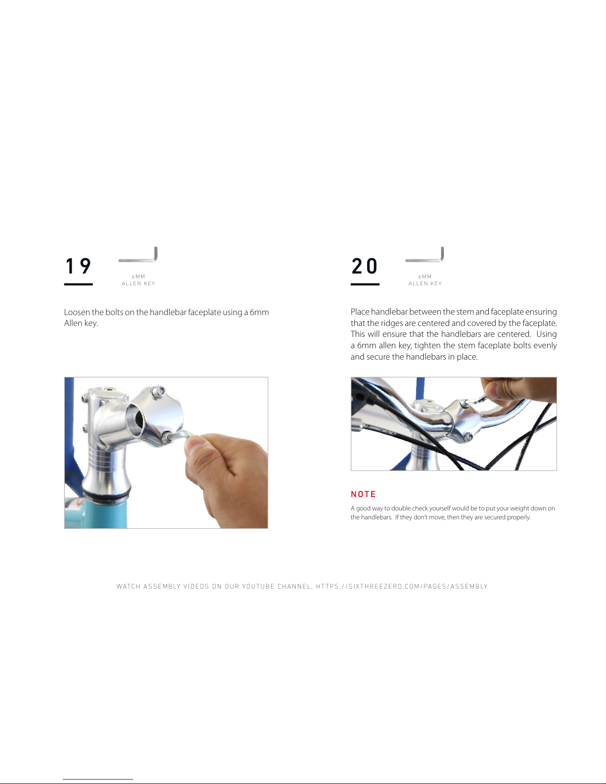
Loosen the bolts on the handlebar faceplate using a 6mm
Allen key.
Place handlebar between the stem and faceplate ensuring
that the ridges are centered and covered by the faceplate.
This will ensure that the handlebars are centered. Using
a 6mm allen key, tighten the stem faceplate bolts evenly
and secure the handlebars in place.
Page 26
HAVING TROUBLE? WANT LIVE HELP? CALL 310.982.2877 OR EMAIL INFO@SIXTHREEZERO.COM.
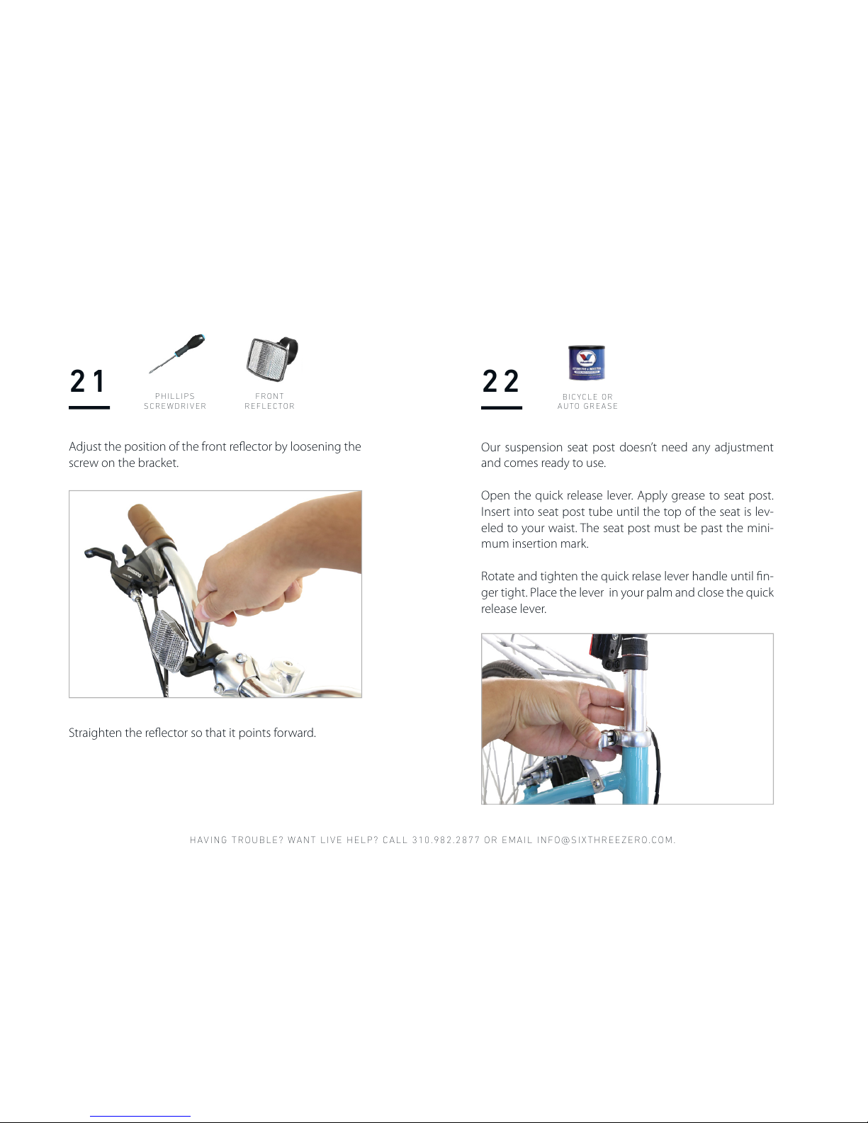
22
Our suspension seat post doesn’t need any adjustment
and comes ready to use.
Open the quick release lever. Apply grease to seat post.
Insert into seat post tube until the top of the seat is lev-
eled to your waist. The seat post must be past the mini-
mum insertion mark.
Rotate and tighten the quick relase lever handle until fin-
ger tight. Place the lever in your palm and close the quick
release lever.
B I CY CL E OR
AUTO GREASE
Adjust the position of the front reflector by loosening the
screw on the bracket.
Straighten the reflector so that it points forward.
21
P H IL LI PS
SCREWDRIVER
FRONT
REFLECTOR
Page 27

WATCH ASSE MBLY VIDEOS ON OUR YOUTUB E CHANNEL , HTTPS:/ /SIXTHREE ZERO.COM/ PAGES/ASSEMB LY
23
Apply grease to the threading on both
pedals.
Select the pedal stamped R (located on the
tip of the threading) and locate the right side
of the bike (with the chain and chain guard).
Align threading with the right crank arm,
and turn the pedal clockwise to tighten it.
Locate the pedal stamped L and align
with the left crank arm. The left side
pedal is reverse-threaded, tightening in a
counterclockwise direction.
B I CY CL E OR
AUTO GREASE
15MM
MULTI-TOOL
PEDALS
We recommend hand tightening initially and
following up with a 15mm wrench to fully
tighten down the pedals.
RIGHT PEDAL LEFT PEDAL
Page 28
HAVING TROUBLE? WANT LIVE HELP? CALL 310.982.2877 OR EMAIL INFO@SIXTHREEZERO.COM.
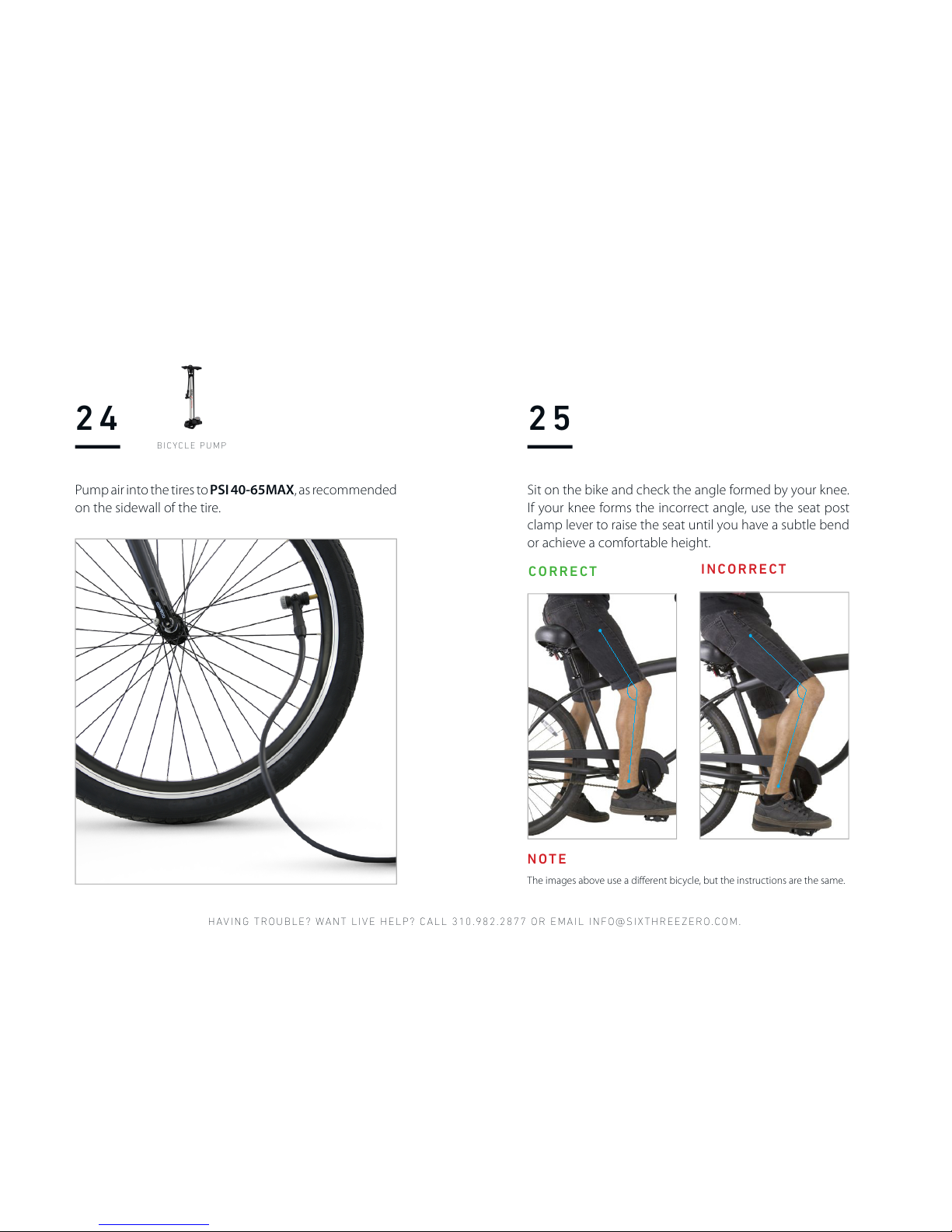
24
Pump air into the tires to PSI 40-65MAX, as recommended
on the sidewall of the tire.
BICYCLE PUMP
Sit on the bike and check the angle formed by your knee.
If your knee forms the incorrect angle, use the seat post
clamp lever to raise the seat until you have a subtle bend
or achieve a comfortable height.
25
CORRECT
INCORRECT
The images above use a different bicycle, but the instructions are the same.
NOTE
Page 29
WATCH ASSE MBLY VIDEOS ON OUR YOUTUB E CHANNEL , HTTPS:/ /SIXTHREE ZERO.COM/ PAGES/ASSEMB LY
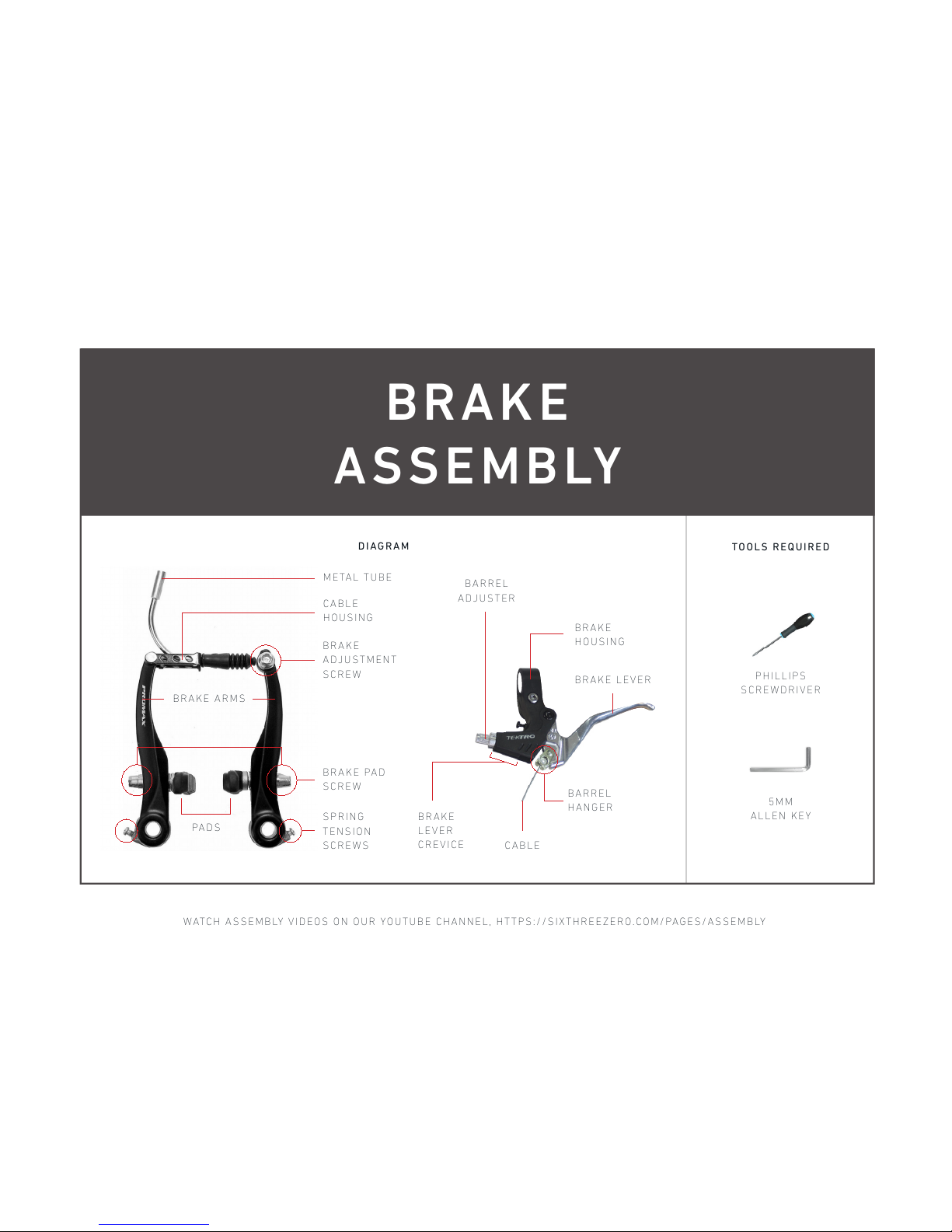
BRAKE
ASSEMBLY
METAL TUBE
C A B L E
HOUSING
B R A K E
ADJUSTMENT
SCREW
BRAKE LEVER
B A R R EL
HANGER
CABLE
B R A K E
HOUSING
BARREL
ADJUSTER
B R A K E
LEVER
CREVICE
S P R I NG
TENSION
SCREWS
B R A K E PA D
SCREW
BRAKE ARMS
PAD S
P H I L LI P S
SCREWDRIVER
TOOLS REQU IRED
5MM
ALLEN KEY
DIAGRAM
Page 30
HAVING TROUBLE? WANT LIVE HELP? CALL 310.982.2877 OR EMAIL INFO@SIXTHREEZERO.COM.
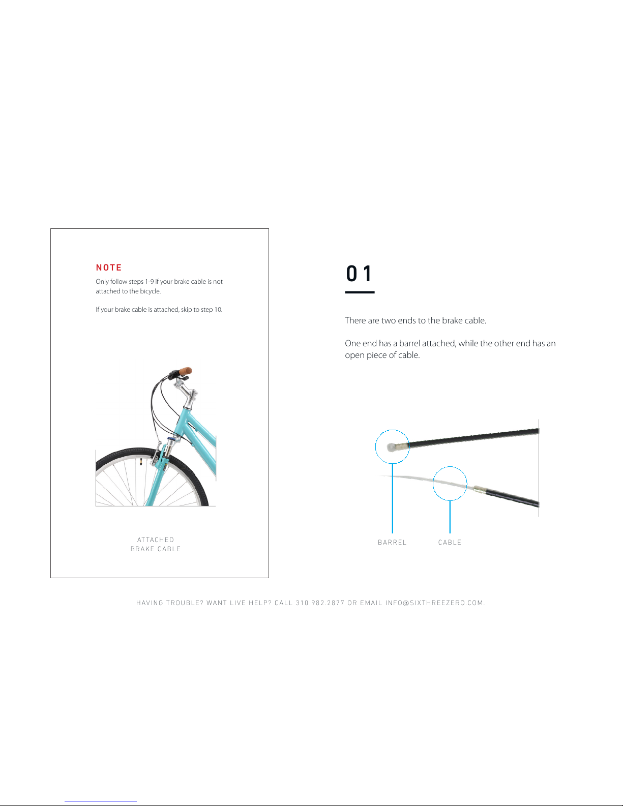
ATTA C HED
BRAKE CABLE
Only follow steps 1-9 if your brake cable is not
attached to the bicycle.
If your brake cable is attached, skip to step 10.
NOTE
BARREL CABLE
01
There are two ends to the brake cable.
One end has a barrel attached, while the other end has an
open piece of cable.
Page 31
WATCH ASSE MBLY VIDEOS ON OUR YOUTUB E CHANNEL , HTTPS:/ /SIXTHREE ZERO.COM/ PAGES/ASSEMB LY
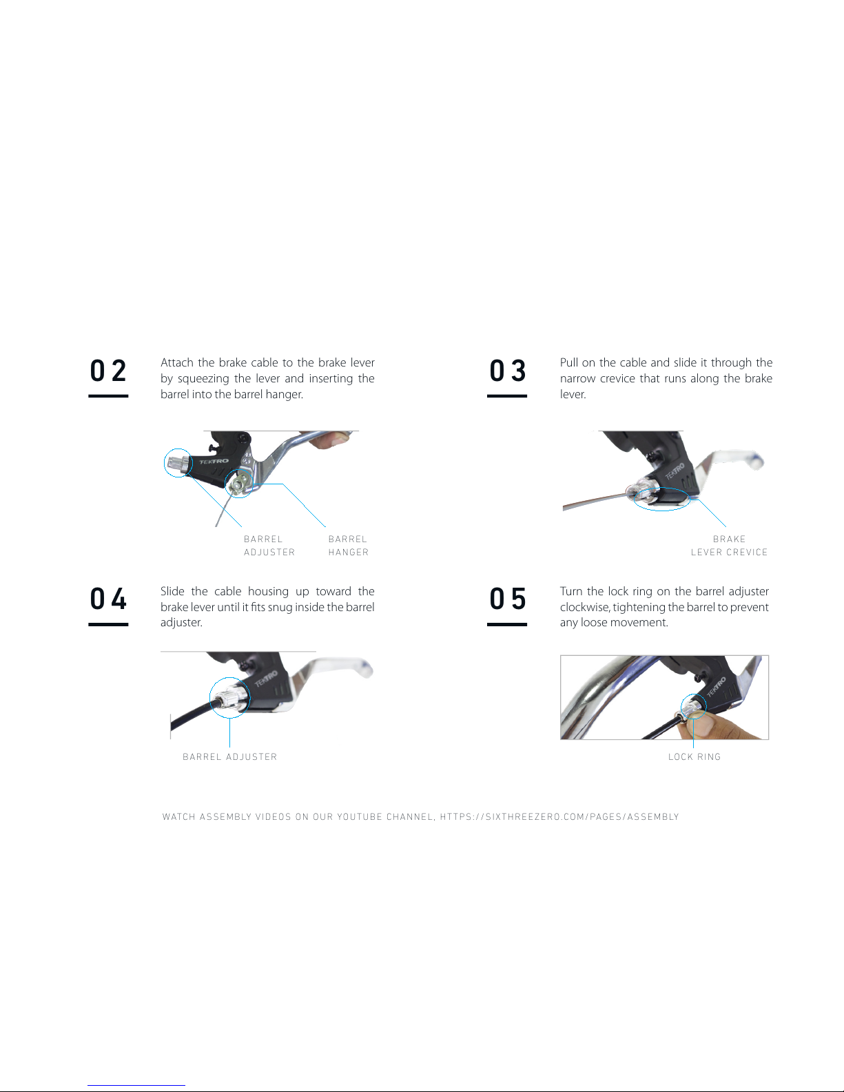
02
04
Slide the cable housing up toward the
brake lever until it fits snug inside the barrel
adjuster.
05
Turn the lock ring on the barrel adjuster
clockwise, tightening the barrel to prevent
any loose movement.
LOCK RI NG
03
Pull on the cable and slide it through the
narrow crevice that runs along the brake
lever.
B R A K E
LEVER CREVICE
B A R R EL
HANGER
B A R R EL
ADJUSTER
BARREL ADJUSTER
Attach the brake cable to the brake lever
by squeezing the lever and inserting the
barrel into the barrel hanger.
Page 32
HAVING TROUBLE? WANT LIVE HELP? CALL 310.982.2877 OR EMAIL INFO@SIXTHREEZERO.COM.
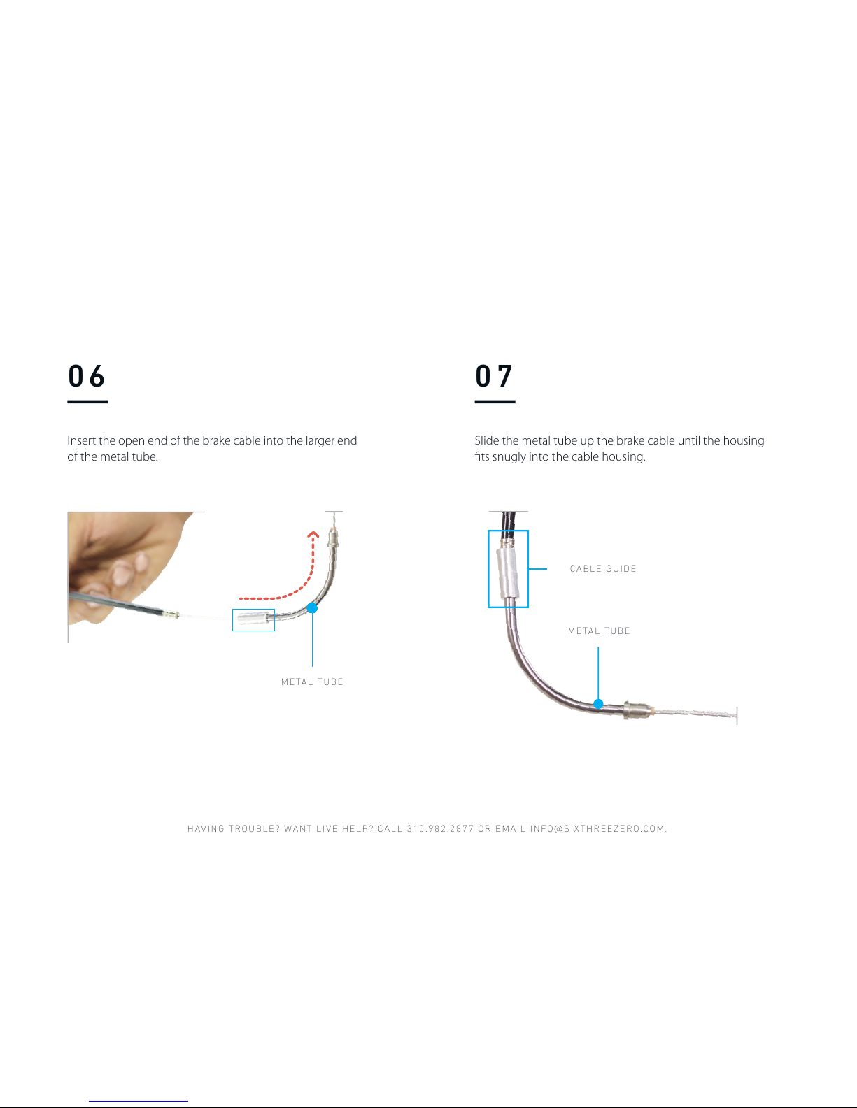
07
Slide the metal tube up the brake cable until the housing
fits snugly into the cable housing.
CABLE GUIDE
METAL TUBE
M E TA L TU BE
06
Insert the open end of the brake cable into the larger end
of the metal tube.
Page 33
WATCH ASSE MBLY VIDEOS ON OUR YOUTUB E CHANNEL , HTTPS:/ /SIXTHREE ZERO.COM/ PAGES/ASSEMB LY
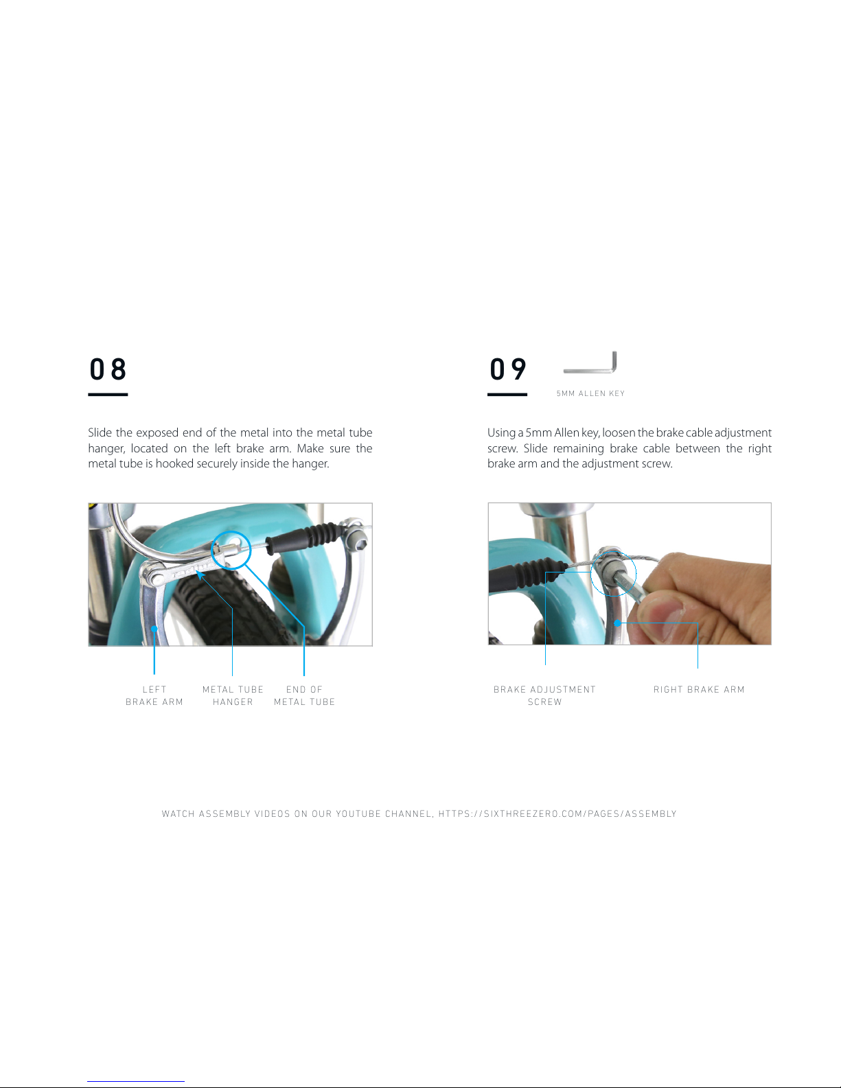
08
Slide the exposed end of the metal into the metal tube
hanger, located on the left brake arm. Make sure the
metal tube is hooked securely inside the hanger.
LEFT
BRAKE ARM
METAL TUBE
HANGER
E N D OF
METAL TUBE
Using a 5mm Allen key, loosen the brake cable adjustment
screw. Slide remaining brake cable between the right
brake arm and the adjustment screw.
BRAKE ADJUSTMENT
SCREW
RIGHT BRAKE ARM
09
5MM ALLEN KEY
Page 34
HAVING TROUBLE? WANT LIVE HELP? CALL 310.982.2877 OR EMAIL INFO@SIXTHREEZERO.COM.
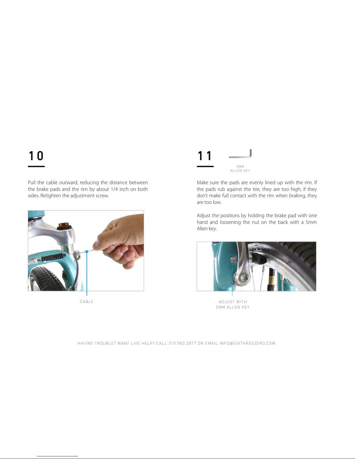
10
Pull the cable outward, reducing the distance between
the brake pads and the rim by about 1/4 inch on both
sides. Retighten the adjustment screw.
CABLE
11
Make sure the pads are evenly lined up with the rim. If
the pads rub against the tire, they are too high; if they
don’t make full contact with the rim when braking, they
are too low.
Adjust the positions by holding the brake pad with one
hand and loosening the nut on the back with a 5mm
Allen key.
5 M M
ALLEN KEY
A D J U S T W I T H
5MM ALLEN KEY
Page 35
WATCH ASSE MBLY VIDEOS ON OUR YOUTUB E CHANNEL , HTTPS:/ /SIXTHREE ZERO.COM/ PAGES/ASSEMB LY
12
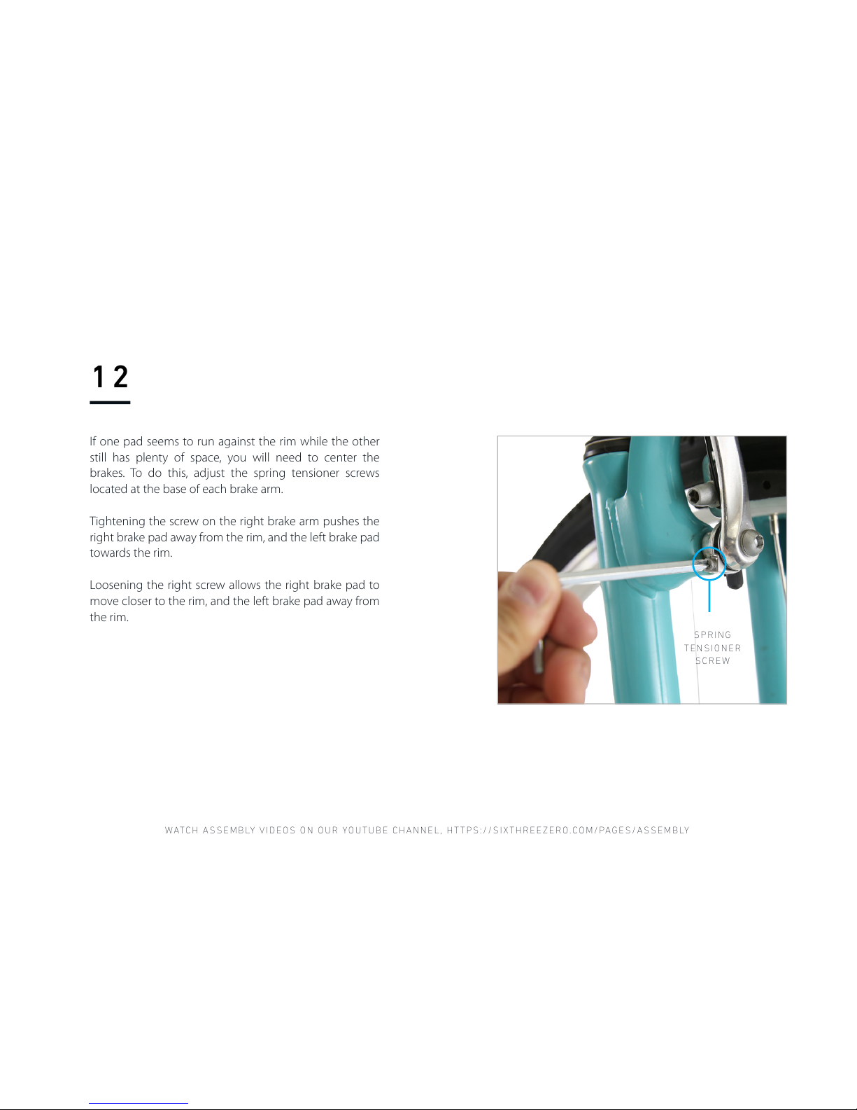
If one pad seems to run against the rim while the other
still has plenty of space, you will need to center the
brakes. To do this, adjust the spring tensioner screws
located at the base of each brake arm.
Tightening the screw on the right brake arm pushes the
right brake pad away from the rim, and the left brake pad
towards the rim.
Loosening the right screw allows the right brake pad to
move closer to the rim, and the left brake pad away from
the rim.
S P R I NG
TENSIONER
SCREW
Page 36
HAVING TROUBLE? WANT LIVE HELP? CALL 310.982.2877 OR EMAIL INFO@SIXTHREEZERO.COM.
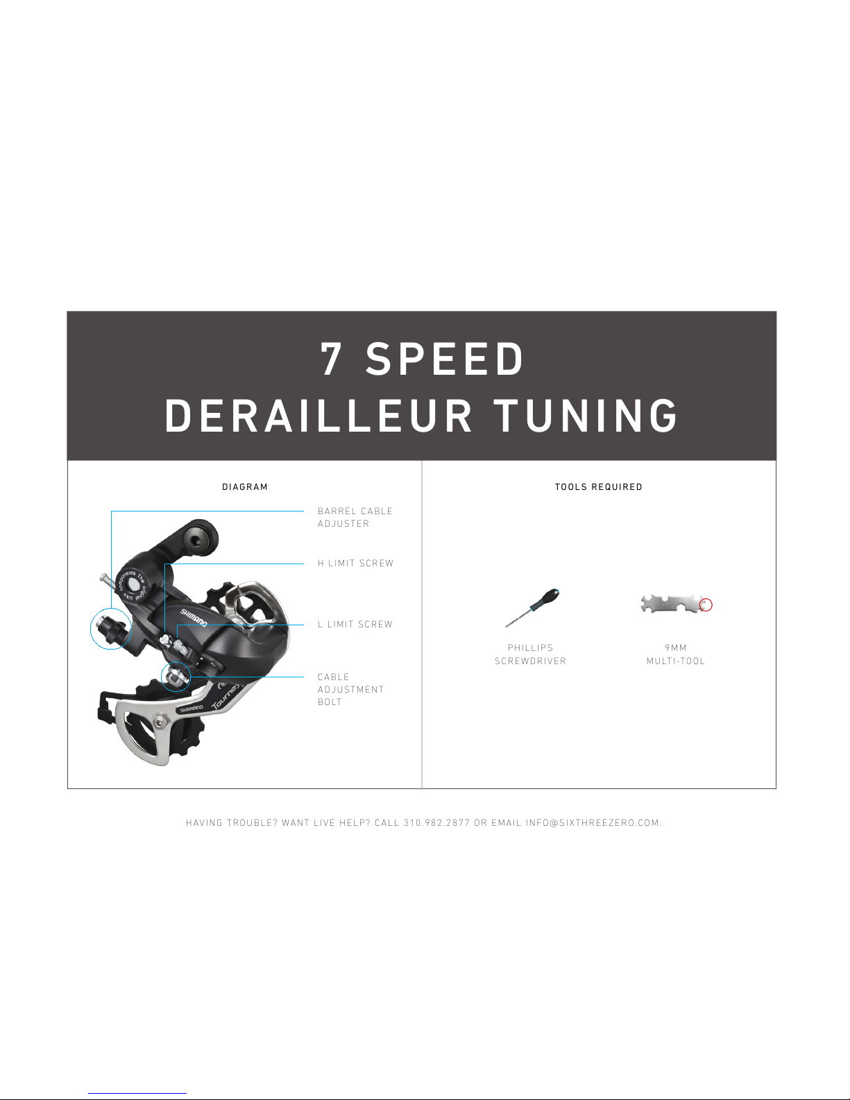
7 SPEED
DERAILLEUR TUNING
9MM
MULTI-TOOL
P H I L LI P S
SCREWDRIVER
H LIMIT SCREW
DIAGRAM TOOLS REQU IRED
L LIMIT SCREW
C A B L E
ADJUSTMENT
BOLT
B A R R EL CA BL E
ADJUSTER
Page 37
WATCH ASSE MBLY VIDEOS ON OUR YOUTUB E CHANNEL , HTTPS:/ /SIXTHREE ZERO.COM/ PAGES/ASSEMB LY
01
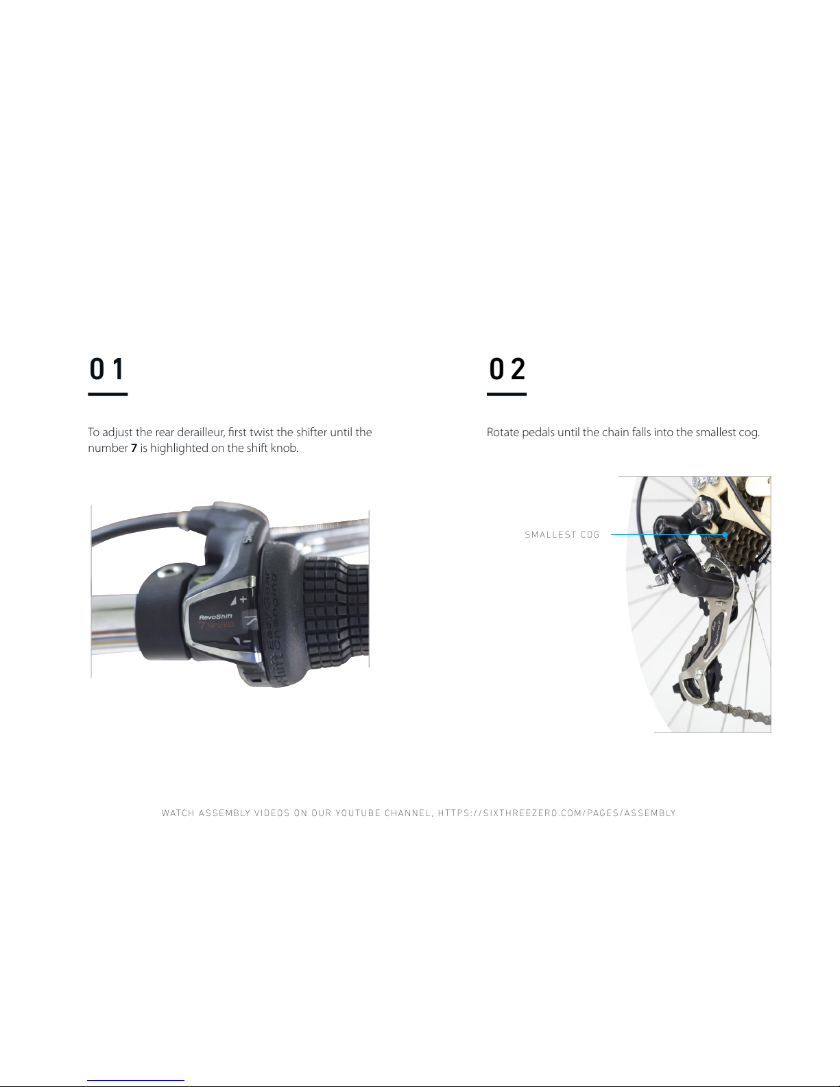
To adjust the rear derailleur, first twist the shifter until the
number 7 is highlighted on the shift knob.
02
Rotate pedals until the chain falls into the smallest cog.
SMALLEST COG
Page 38
HAVING TROUBLE? WANT LIVE HELP? CALL 310.982.2877 OR EMAIL INFO@SIXTHREEZERO.COM.
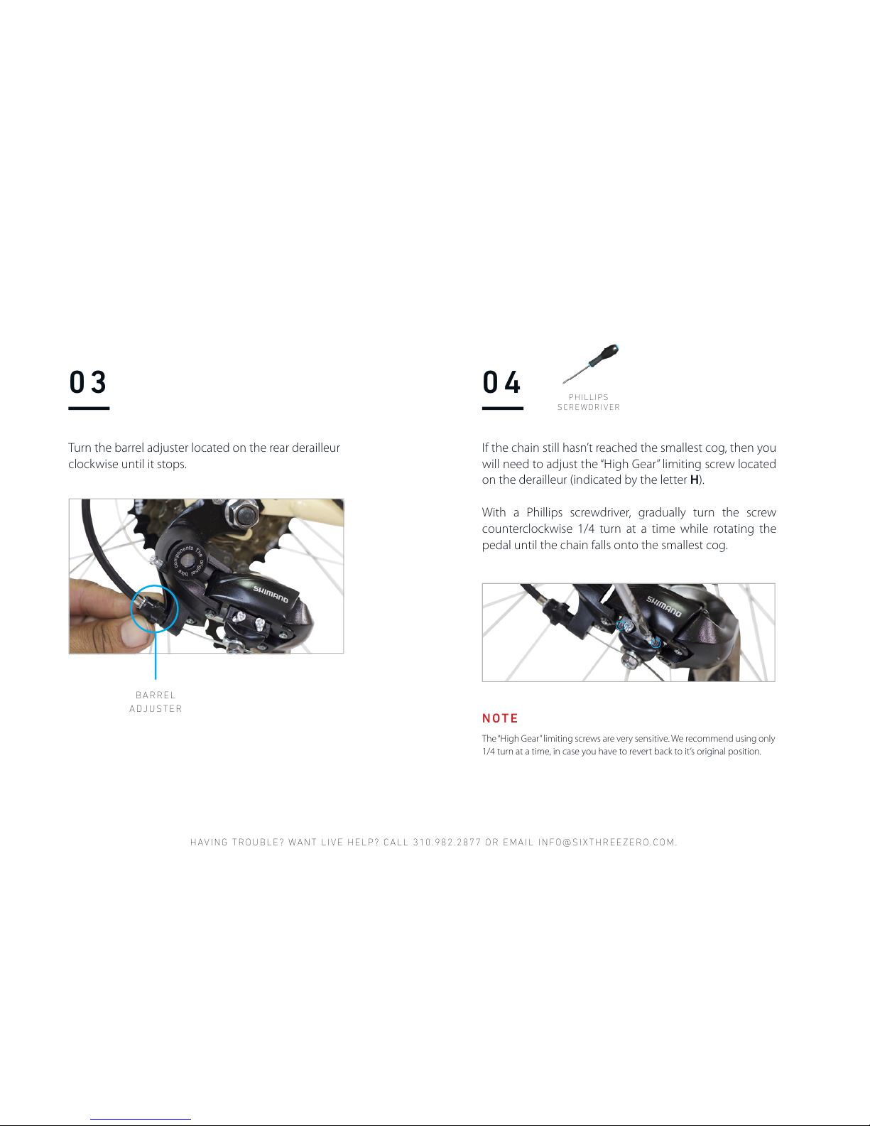
B A R R EL
ADJUSTER
03
Turn the barrel adjuster located on the rear derailleur
clockwise until it stops.
04
If the chain still hasn’t reached the smallest cog, then you
will need to adjust the “High Gear” limiting screw located
on the derailleur (indicated by the letter H).
With a Phillips screwdriver, gradually turn the screw
counterclockwise 1/4 turn at a time while rotating the
pedal until the chain falls onto the smallest cog.
P H IL LI PS
SCREWDRIVER
The “High Gear” limiting screws are very sensitive. We recommend using only
1/4 turn at a time, in case you have to revert back to it’s original position.
NOTE
Page 39
WATCH ASSE MBLY VIDEOS ON OUR YOUTUB E CHANNEL , HTTPS:/ /SIXTHREE ZERO.COM/ PAGES/ASSEMB LY
Each gear should shift with a corresponding
“click” sound.
NOTE
05
06
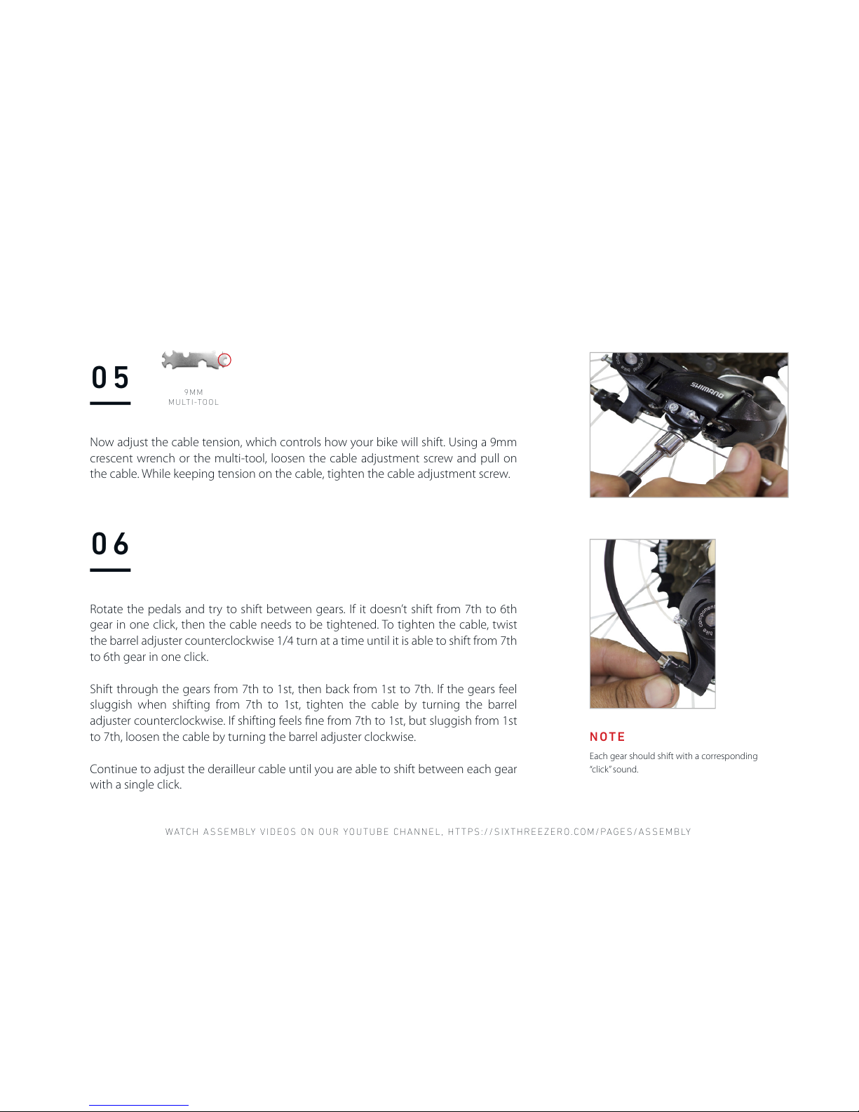
Now adjust the cable tension, which controls how your bike will shift. Using a 9mm
crescent wrench or the multi-tool, loosen the cable adjustment screw and pull on
the cable. While keeping tension on the cable, tighten the cable adjustment screw.
Rotate the pedals and try to shift between gears. If it doesn’t shift from 7th to 6th
gear in one click, then the cable needs to be tightened. To tighten the cable, twist
the barrel adjuster counterclockwise 1/4 turn at a time until it is able to shift from 7th
to 6th gear in one click.
Shift through the gears from 7th to 1st, then back from 1st to 7th. If the gears feel
sluggish when shifting from 7th to 1st, tighten the cable by turning the barrel
adjuster counterclockwise. If shifting feels fine from 7th to 1st, but sluggish from 1st
to 7th, loosen the cable by turning the barrel adjuster clockwise.
Continue to adjust the derailleur cable until you are able to shift between each gear
with a single click.
9MM
MULTI-TOOL
Page 40
HAVING TROUBLE? WANT LIVE HELP? CALL 310.982.2877 OR EMAIL INFO@SIXTHREEZERO.COM.
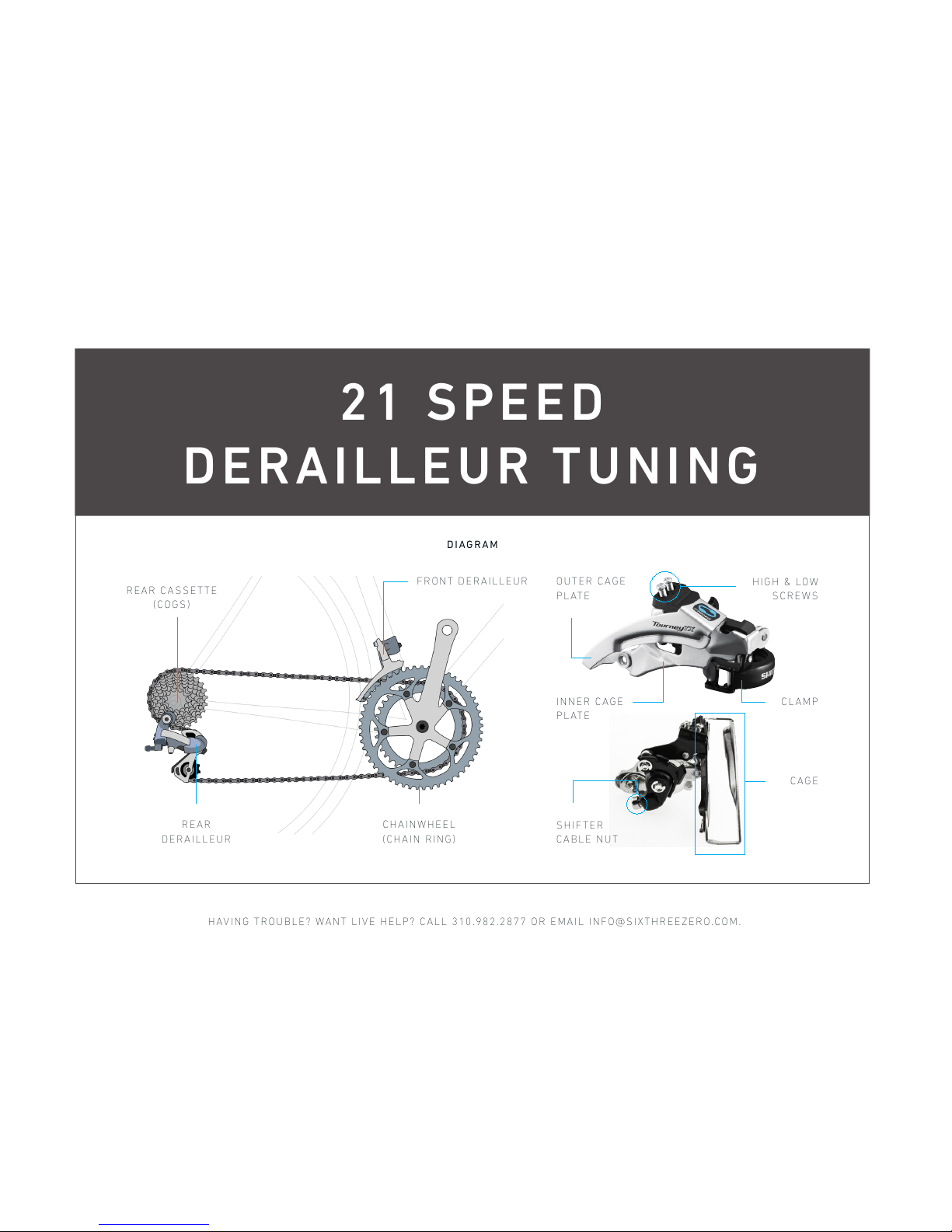
21 SPEED
DERAILLEUR TUNING
DIAGRAM
FRONT DERAILLEUR
CHAINWHEEL
(CHAIN RING)
REAR
DERAILLEUR
REAR CASSETTE
(COGS)
I N N E R C AG E
PLATE
CLAMP
CAGE
O U T E R C AG E
PLATE
HIGH & LOW
SCREWS
S H I F TE R
CABLE NUT
Page 41
WATCH ASSE MBLY VIDEOS ON OUR YOUTUB E CHANNEL , HTTPS:/ /SIXTHREE ZERO.COM/ PAGES/ASSEMB LY
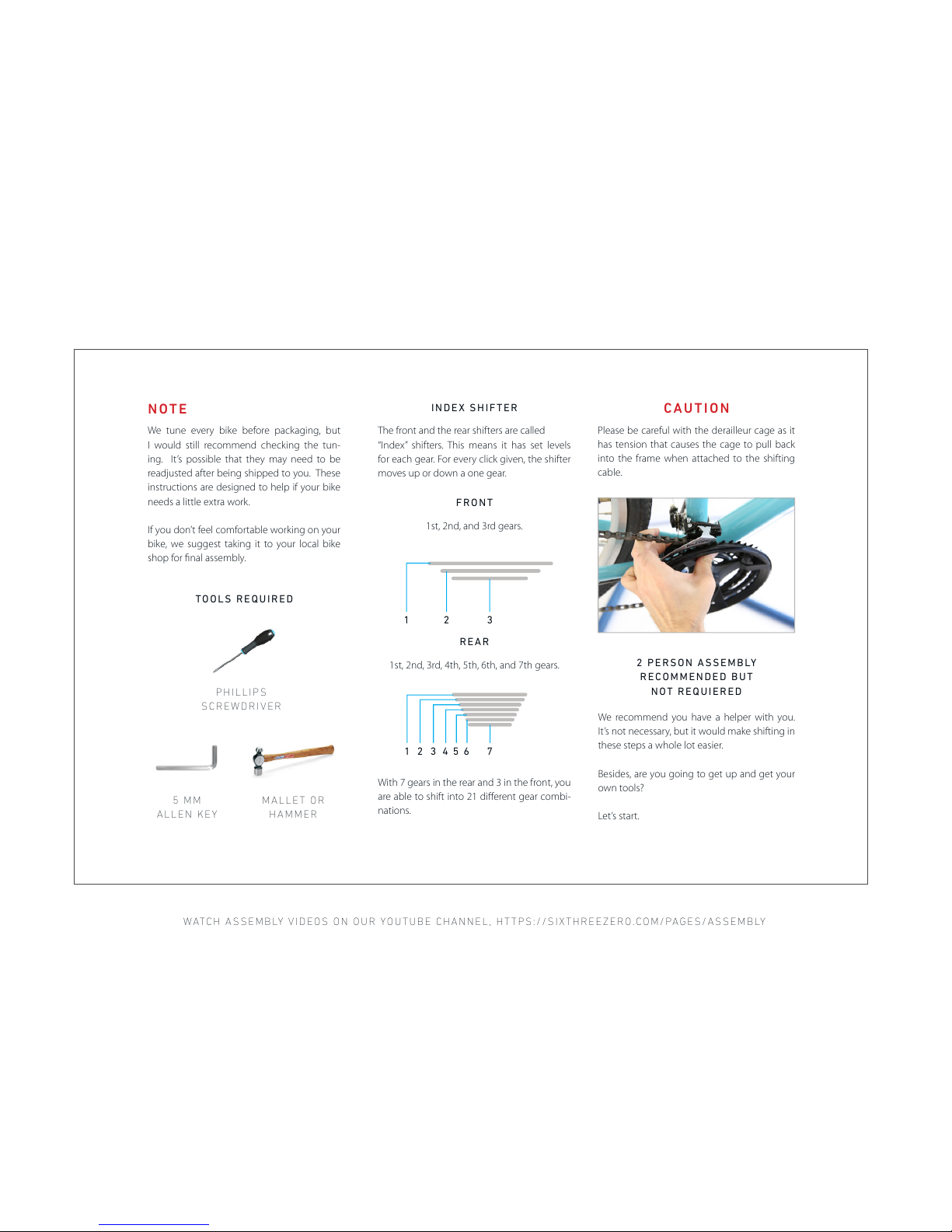
The front and the rear shifters are called
“Index” shifters. This means it has set levels
for each gear. For every click given, the shifter
moves up or down a one gear.
With 7 gears in the rear and 3 in the front, you
are able to shift into 21 different gear combi-
nations.
1st, 2nd, and 3rd gears.
1st, 2nd, 3rd, 4th, 5th, 6th, and 7th gears.
P H I L LI P S
SCREWDRIVER
TOOLS REQU IRED
5 MM
ALLEN KEY
M A L L ET OR
HAMMER
We tune every bike before packaging, but
I would still recommend checking the tun-
ing. It ’s possible that they may need to be
readjusted after being shipped to you. These
instructions are designed to help if your bike
needs a little extra work.
If you don’t feel comfortable working on your
bike, we suggest taking it to your local bike
shop for final assembly.
NOTE
INDEX SHIFTER
FRONT
REAR
1 2 3
1 2 4 5 6 73
We recommend you have a helper with you.
It’s not necessary, but it would make shifting in
these steps a whole lot easier.
Besides, are you going to get up and get your
own tools?
Let’s start.
2 PERSON ASSEMBLY
RECOMMENDED BUT
NOT REQUIERED
CAUTION
Please be careful with the derailleur cage as it
has tension that causes the cage to pull back
into the frame when attached to the shifting
cable.
Page 42
HAVING TROUBLE? WANT LIVE HELP? CALL 310.982.2877 OR EMAIL INFO@SIXTHREEZERO.COM.
01
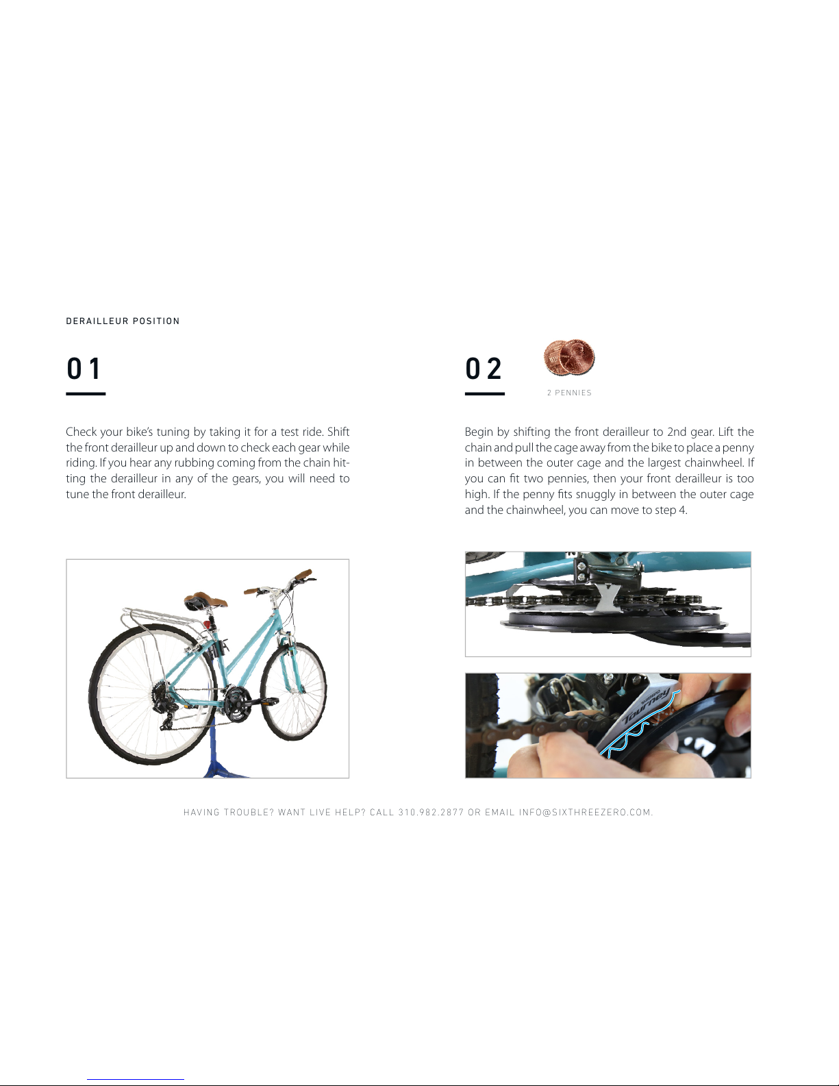
Check your bike’s tuning by taking it for a test ride. Shift
the front derailleur up and down to check each gear while
riding. If you hear any rubbing coming from the chain hit-
ting the derailleur in any of the gears, you will need to
tune the front derailleur.
02
Begin by shifting the front derailleur to 2nd gear. Lift the
chain and pull the cage away from the bike to place a penny
in between the outer cage and the largest chainwheel. If
you can fit two pennies, then your front derailleur is too
high. If the penny fits snuggly in between the outer cage
and the chainwheel, you can move to step 4.
2 PENNIES
DERAILLEUR POSITION
Page 43
WATCH ASSE MBLY VIDEOS ON OUR YOUTUB E CHANNEL , HTTPS:/ /SIXTHREE ZERO.COM/ PAGES/ASSEMB LY
03
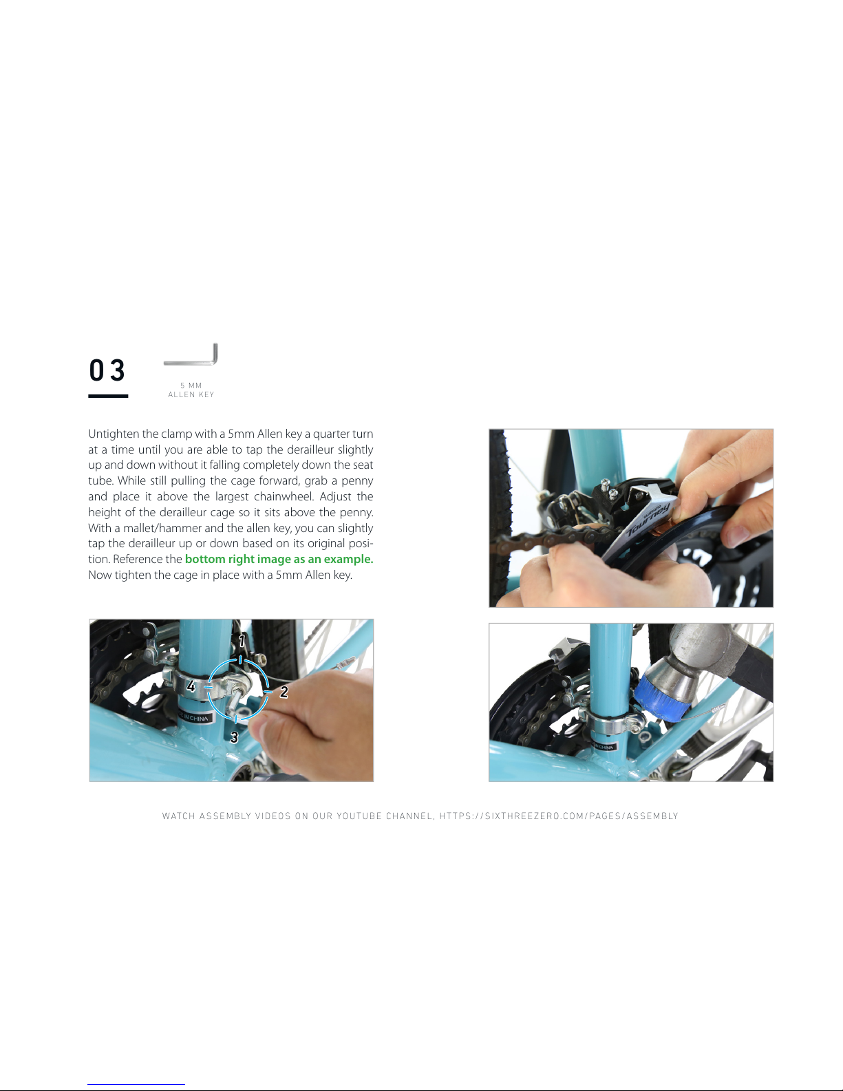
Untighten the clamp with a 5mm Allen key a quarter turn
at a time until you are able to tap the derailleur slightly
up and down without it falling completely down the seat
tube. While still pulling the cage forward, grab a penny
and place it above the largest chainwheel. Adjust the
height of the derailleur cage so it sits above the penny.
With a mallet/hammer and the allen key, you can slightly
tap the derailleur up or down based on its original posi-
tion. Reference the bottom right image as an example.
Now tighten the cage in place with a 5mm Allen key.
1
2
3
4
5 MM
ALLEN KEY
Page 44
HAVING TROUBLE? WANT LIVE HELP? CALL 310.982.2877 OR EMAIL INFO@SIXTHREEZERO.COM.
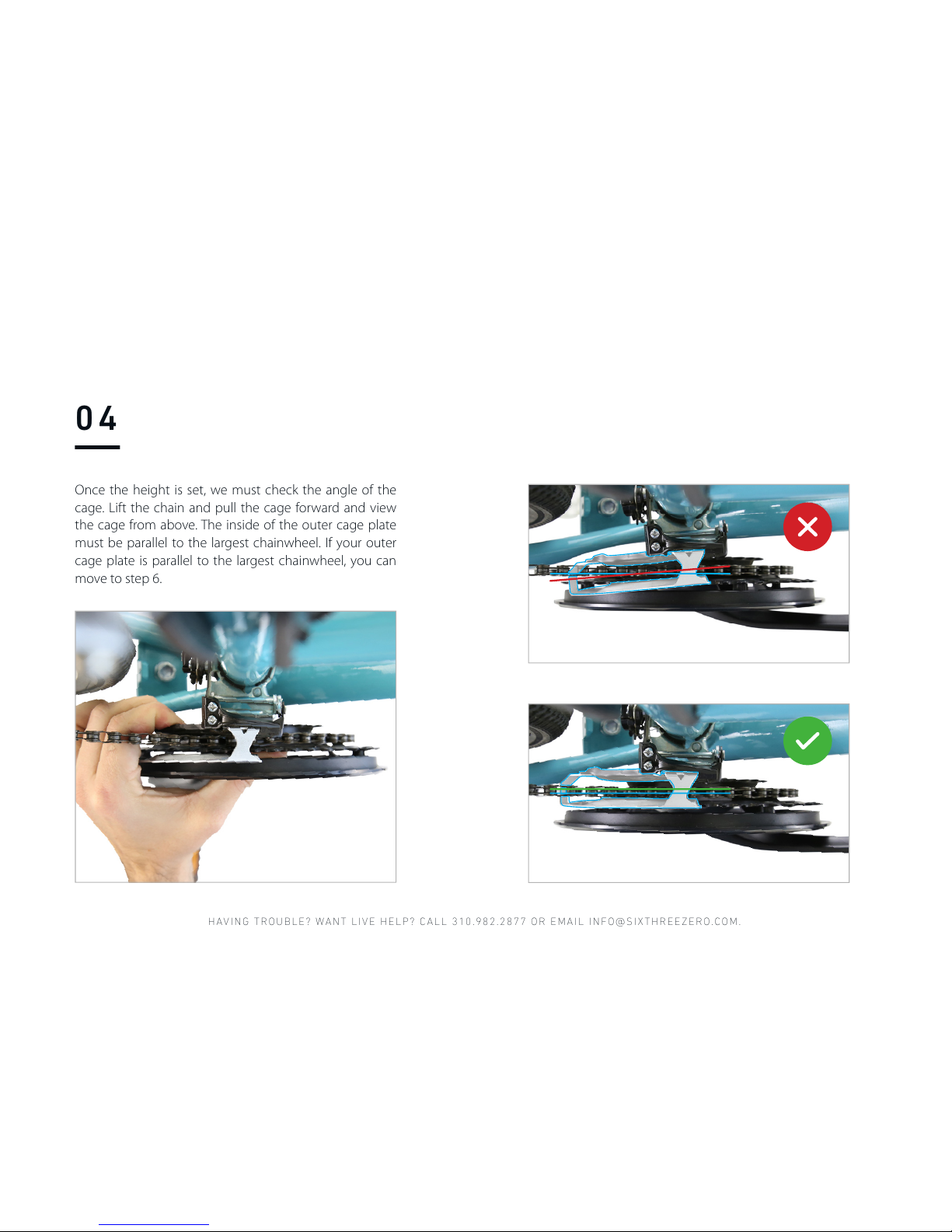
Once the height is set, we must check the angle of the
cage. Lift the chain and pull the cage forward and view
the cage from above. The inside of the outer cage plate
must be parallel to the largest chainwheel. If your outer
cage plate is parallel to the largest chainwheel, you can
move to step 6.
04
Page 45
WATCH ASSE MBLY VIDEOS ON OUR YOUTUB E CHANNEL , HTTPS:/ /SIXTHREE ZERO.COM/ PAGES/ASSEMB LY
5 MM
ALLEN KEY
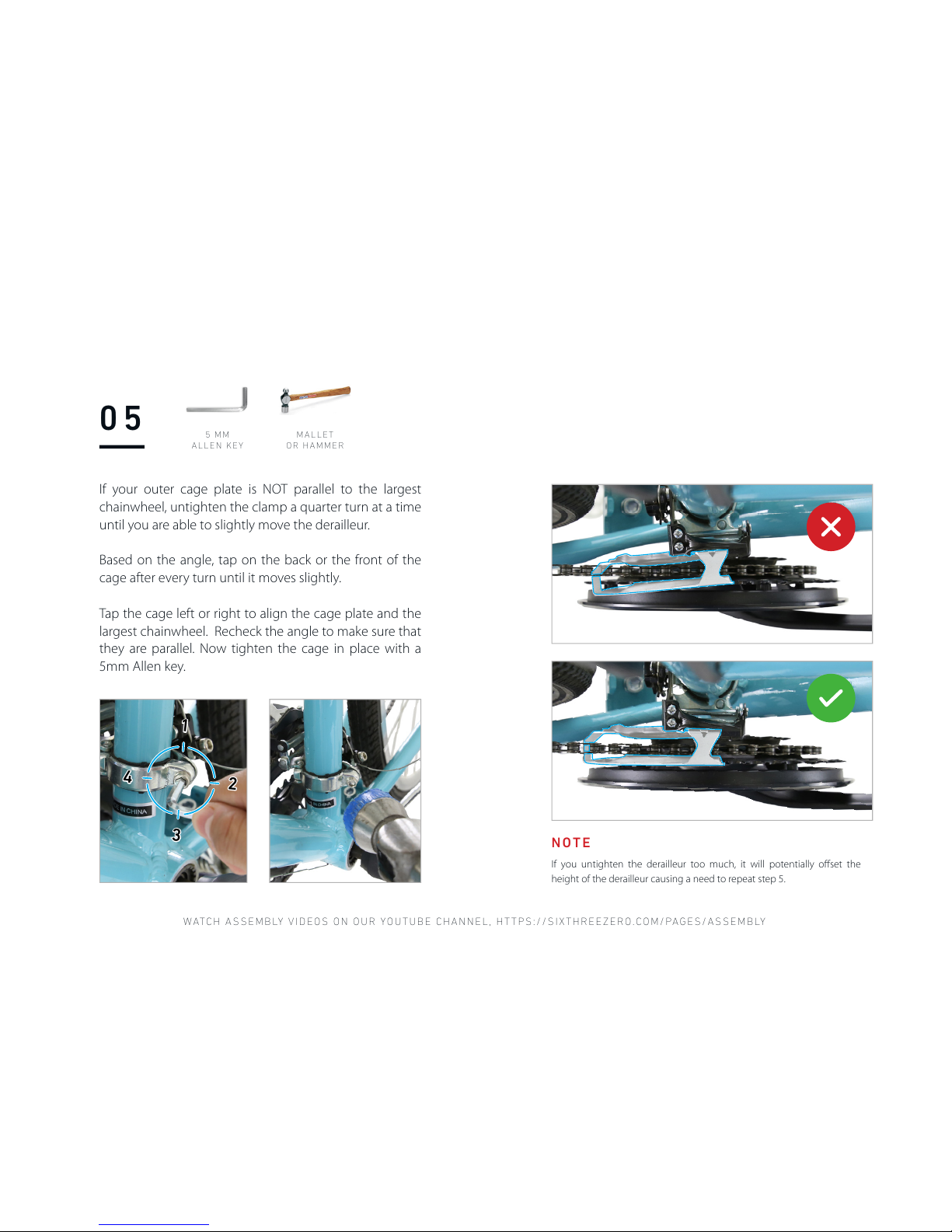
If your outer cage plate is NOT parallel to the largest
chainwheel, untighten the clamp a quarter turn at a time
until you are able to slightly move the derailleur.
Based on the angle, tap on the back or the front of the
cage after every turn until it moves slightly.
Tap the cage left or right to align the cage plate and the
largest chainwheel. Recheck the angle to make sure that
they are parallel. Now tighten the cage in place with a
5mm Allen key.
05
MALLET
OR HAMMER
If you untighten the derailleur too much, it will potentially offset the
height of the derailleur causing a need to repeat step 5.
NOTE
1
2
3
4
Page 46
HAVING TROUBLE? WANT LIVE HELP? CALL 310.982.2877 OR EMAIL INFO@SIXTHREEZERO.COM.
Derailleurs work off of tension, and this is
the reason that they are designed with High
and Low Limiter screws. The High and Low
Limiters essentially act as boundaries so that
no matter how much tension you put into
or take off the shifter cable, the derailleur will
not go past the largest or smallest gears. The
High (H) screw is the limiter for the largest
gear, and the Low (L) screw is the limiter for
the smallest gear.
NOTE
COUNTERCLOCKWISE
CLOCKWISE
Turning the L & H counterclockwise shortens
the range where the derailleur cage can travel.
Turning the L & H clockwise increases the
range where the derailleur cage can travel.
L H
L H
06
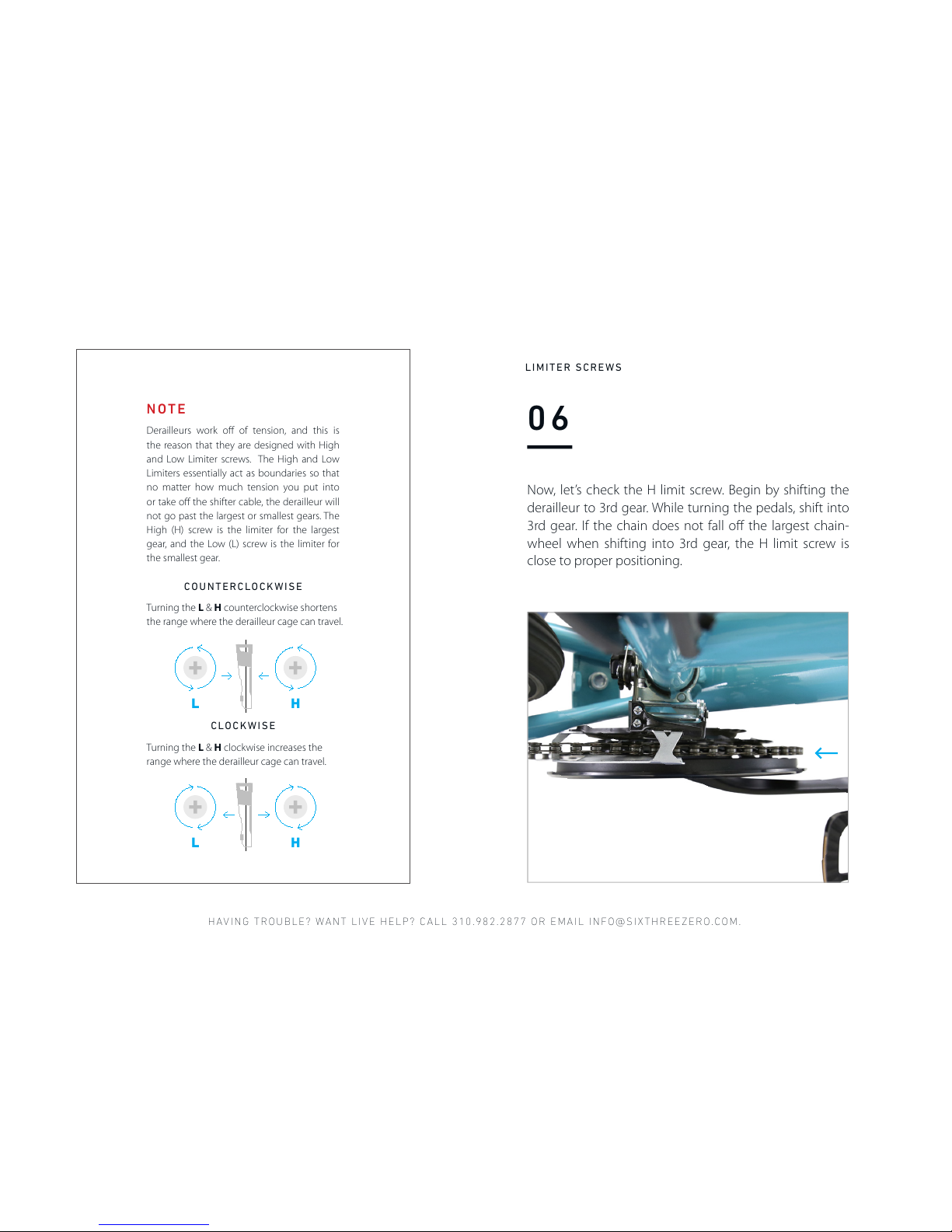
Now, let’s check the H limit screw. Begin by shifting the
derailleur to 3rd gear. While turning the pedals, shift into
3rd gear. If the chain does not fall off the largest chain-
wheel when shifting into 3rd gear, the H limit screw is
close to proper positioning.
LIMITER SCREWS
Page 47
WATCH ASSE MBLY VIDEOS ON OUR YOUTUB E CHANNEL , HTTPS:/ /SIXTHREE ZERO.COM/ PAGES/ASSEMB LY
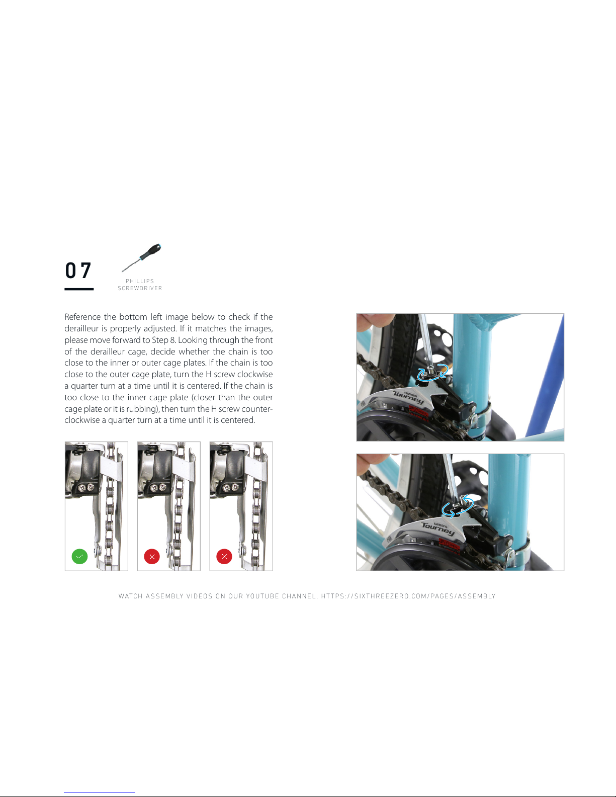
Reference the bottom left image below to check if the
derailleur is properly adjusted. If it matches the images,
please move forward to Step 8. Looking through the front
of the derailleur cage, decide whether the chain is too
close to the inner or outer cage plates. If the chain is too
close to the outer cage plate, turn the H screw clockwise
a quarter turn at a time until it is centered. If the chain is
too close to the inner cage plate (closer than the outer
cage plate or it is rubbing), then turn the H screw counter-
clockwise a quarter turn at a time until it is centered.
07
P H IL LI PS
SCREWDRIVER
Page 48
HAVING TROUBLE? WANT LIVE HELP? CALL 310.982.2877 OR EMAIL INFO@SIXTHREEZERO.COM.
08
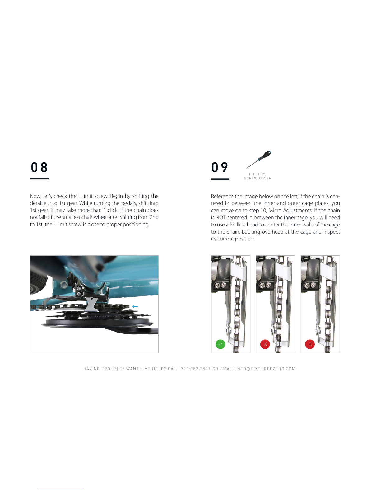
Now, let’s check the L limit screw. Begin by shifting the
derailleur to 1st gear. While turning the pedals, shift into
1st gear. It may take more than 1 click. If the chain does
not fall off the smallest chainwheel after shifting from 2nd
to 1st, the L limit screw is close to proper positioning.
Reference the image below on the left, if the chain is cen-
tered in between the inner and outer cage plates, you
can move on to step 10, Micro Adjustments. If the chain
is NOT centered in between the inner cage, you will need
to use a Phillips head to center the inner walls of the cage
to the chain. Looking overhead at the cage and inspect
its current position.
09
P H IL LI PS
SCREWDRIVER
Page 49
WATCH ASSE MBLY VIDEOS ON OUR YOUTUB E CHANNEL , HTTPS:/ /SIXTHREE ZERO.COM/ PAGES/ASSEMB LY
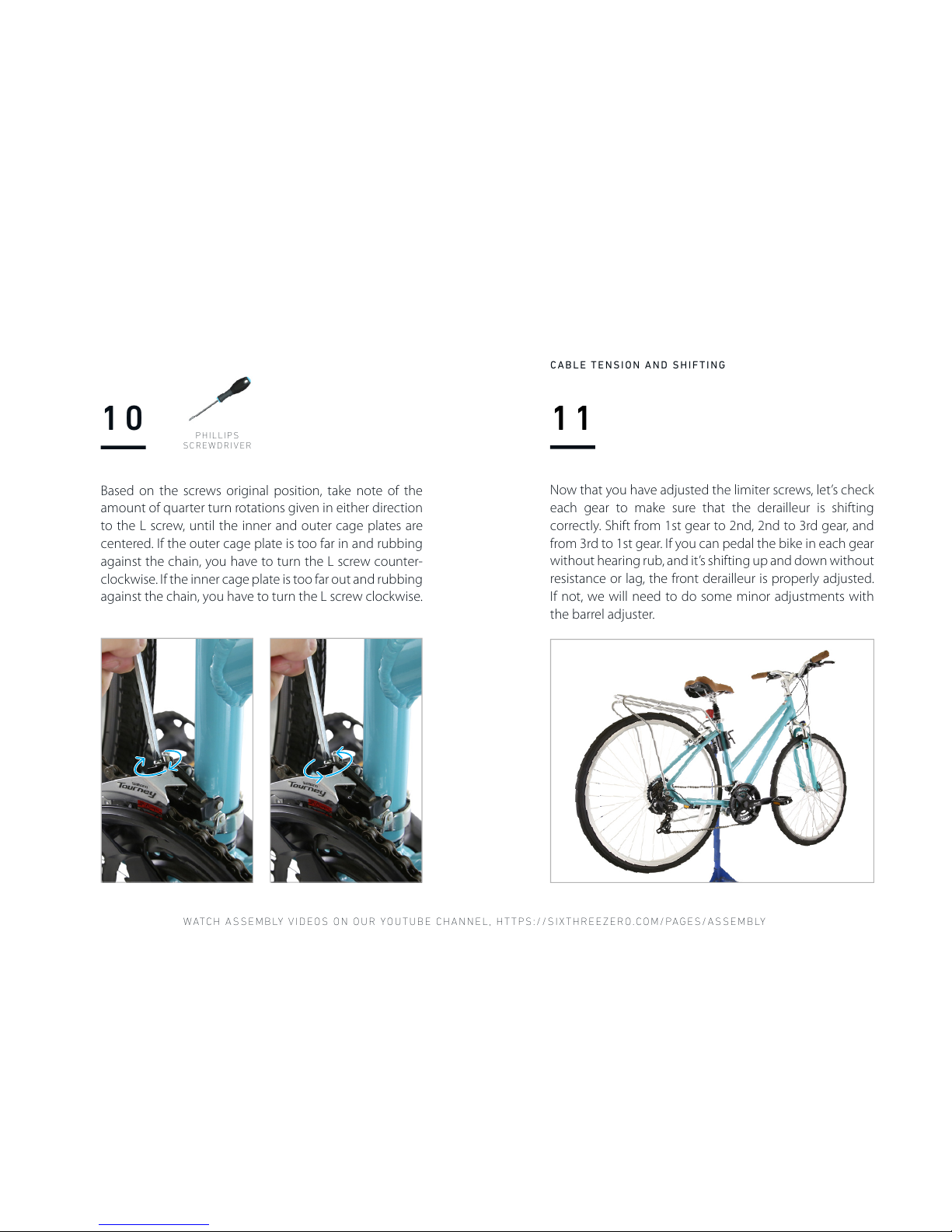
Based on the screws original position, take note of the
amount of quarter turn rotations given in either direction
to the L screw, until the inner and outer cage plates are
centered. If the outer cage plate is too far in and rubbing
against the chain, you have to turn the L screw counter-
clockwise. If the inner cage plate is too far out and rubbing
against the chain, you have to turn the L screw clockwise.
10
P H IL LI PS
SCREWDRIVER
11
Now that you have adjusted the limiter screws, let’s check
each gear to make sure that the derailleur is shifting
correctly. Shift from 1st gear to 2nd, 2nd to 3rd gear, and
from 3rd to 1st gear. If you can pedal the bike in each gear
without hearing rub, and it’s shifting up and down without
resistance or lag, the front derailleur is properly adjusted.
If not, we will need to do some minor adjustments with
the barrel adjuster.
CABLE TENSION AND SHIFTING
Page 50
HAVING TROUBLE? WANT LIVE HELP? CALL 310.982.2877 OR EMAIL INFO@SIXTHREEZERO.COM.
12 01
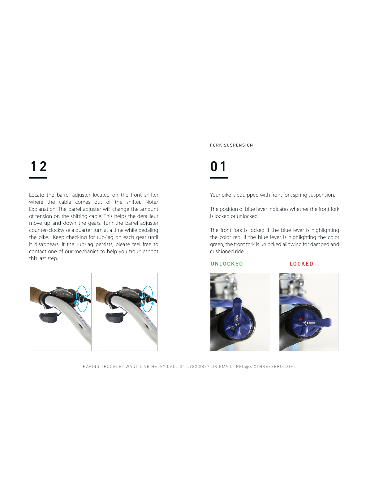
Locate the barrel adjuster located on the front shifter
where the cable comes out of the shifter. Note/
Explanation: The barrel adjuster will change the amount
of tension on the shifting cable. This helps the derailleur
move up and down the gears. Turn the barrel adjuster
counter-clockwise a quarter turn at a time while pedaling
the bike. Keep checking for rub/lag on each gear until
it disappears. If the rub/lag persists, please feel free to
contact one of our mechanics to help you troubleshoot
this last step.
Your bike is equipped with front fork spring suspension.
The position of blue lever indicates whether the front fork
is locked or unlocked.
The front fork is locked if the blue lever is highlighting
the color red. If the blue lever is highlighting the color
green, the front fork is unlocked allowing for damped and
cushioned ride.
FORK SUSPENSION
UNLOCKED LOCKED
Page 51
WATCH ASSE MBLY VIDEOS ON OUR YOUTUB E CHANNEL , HTTPS:/ /SIXTHREE ZERO.COM/ PAGES/ASSEMB LY
02
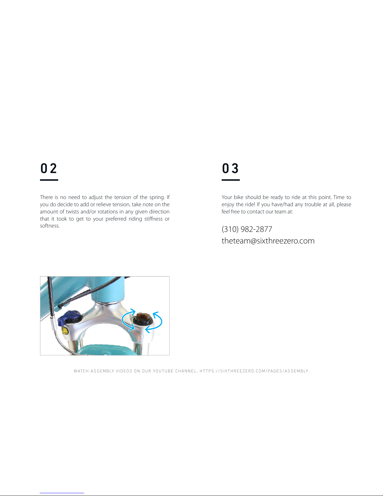
There is no need to adjust the tension of the spring. If
you do decide to add or relieve tension, take note on the
amount of twists and/or rotations in any given direction
that it took to get to your preferred riding stiffness or
softness.
Your bike should be ready to ride at this point. Time to
enjoy the ride! If you have/had any trouble at all, please
feel free to contact our team at:
(310) 982-2877
theteam@sixthreezero.com
03
Page 52

HAVING TROUBLE? WANT LIVE HELP? CALL 310.982.2877 OR EMAIL INFO@SIXTHREEZERO.COM.
Tell us about your assembly experience. If you have/had
any trouble at all or didn’t, and would like to leave feed-
back and help us improve our assembly instructions you
can.
Type this URL into your browser:
goo.gl/kdJeJx
SURVEY
Page 53

WATCH ASSE MBLY VIDEOS ON OUR YOUTUB E CHANNEL , HTTPS:/ /SIXTHREE ZERO.COM/ PAGES/ASSEMB LY
Page 54
You did it! Time to take your brand new bike for a spin.
Still have questions? We’re happy to help.
Want to share your journey with us? We’re happy about that, too.
CONGRATULATIONS
SIXTHREEZERO
THETEAM@SIXTHREEZERO.COM
310.982.2877
Page 55

Page 56

THETEAM@SIXTHREEZERO.COM
310.982.2877
SIXTHREEZERO
LOS ANGELES, CA
 Loading...