

Page 1

IndustrialPro™ and MobilityPro™ Gateway
Wireless Modems
User's Guide
Version 1.11
Novemeber 2, 2011
Page 2

IndustrialPro™ and MobilityPro™ Gateway
2
1.11 – November 2, 2011
User's Guide
No part of this publication, or any software included with it, may be reproduced, stored in a retrieval system, or
transmitted in any form or by any means, including photocopying, electronic, mechanical, recording or otherwise,
without the prior written permission of the copyright holder.
Sixnet, LLC (Sixnet) provides this document as is, without warranty of any kind either expressed or implied including, but
not limited to, the implied warranties of merchantability and fitness for a particular purpose. Sixnet may make changes
of improvements in the equipment, software, or specifications described in this document at any time and without
notice. These changes may be incorporated in new releases of this document.
This document may contain technical inaccuracies or typographical errors. Sixnet and its subsidiaries waive responsibility
for any labor, materials, or costs incurred by any person or party as a result of using this document.
Sixnet and any of its subsidiaries or other affiliates shall not be liable for any damages (including, but not limited to,
consequential, indirect or incidental, special damages, or loss of profits or data) even if they were foreseeable and Sixnet
has been informed of their potential occurrence arising out of or in connection with this document or its use.
Computer Software Copyrights
The products described in this manual include copyrighted Sixnet computer programs stored in semi-conductor
memories or other media. Laws in Canada, the United States and other countries preserve for Sixnet certain rights for
copyrighted computer programs, including the exclusive right to copy or reproduce in any form the copyrighted
computer program. Accordingly, any copyrighted Sixnet computer programs contained in the Sixnet products described
in this manual may not be copied without the express written permission of Sixnet.
Furthermore, the purchase of Sixnet products shall not be deemed to grant either directly or by implication, estoppels,
or otherwise, any license under the copyrights, patents or patent applications of Sixnet, except for the normal nonexclusive, royalty-free license to use that arises by operation of laws in the sale of a product.
Sixnet, LLC
2425, 46th Avenue,
Lachine, Quebec H8T 3C9, Canada
Phone: 1-514-422-9110 option 2
Toll Free: 1-877-422-9110 option 2
Fax: 1-514-422-3338
Web: www.sixnet.com
Copyright © 2010 Sixnet LLC. All rights reserved.
Page 3

IndustrialPro™ and MobilityPro™ Gateway
3
1.11 – November 2, 2011
User's Guide
Liability Notice
While every effort has been made to achieve technical accuracy, information in this document is subject to change
without notice and does not represent a commitment on the part of BlueTree Wireless Data, Inc., or any of its subsidies,
affiliates, agents, licensors, or resellers. There are no warranties, express or implied, with respect to the content of this
document.
Declaration of Conformity
The device complies with Part 15 of FCC rules and with ICES-003 of Industry Canada Rules. Operation is subject to the
following two conditions:
This device may not cause harmful interference
This device must accept any interference received, including interference that may cause undesired
operation
This equipment generates uses and can radiate radio frequency energy and, if not installed and used in accordance with
the manufacturer's instructions, may cause interference harmful to radio communications. However, there is no
guarantee that interference will not occur in a particular installation. If this equipment does cause harmful interference
to radio or television reception, which can be determined by turning the equipment off and on, the user is encouraged
to try to correct the interference by one or more of the following measures:
Reorient or relocate the receiving antenna
Increase the separation between the equipment and receiver
Connect the equipment into an outlet on a circuit different from that to which the receiver is
connected
Consult the dealer or an experienced radio/TV technician for help.
WARNING
To comply with RSS-102 Health Canada Safety Code 6, the antenna(s) used for this transmitter must be installed to
provide a separation distance of at least 10 cm from all persons and must not be co-located or operating in conjunction
with any other antenna or transmitter. Users and Installers must be provided with antenna installation instruction and
transmitter operating conditions for satisfying RF exposure compliance.
BT-6000 series barrel power connector shall not be used in hazardous locations.
Copyright © 2010 Sixnet LLC. All rights reserved.
Page 4
4
1.11 – November 2, 2011
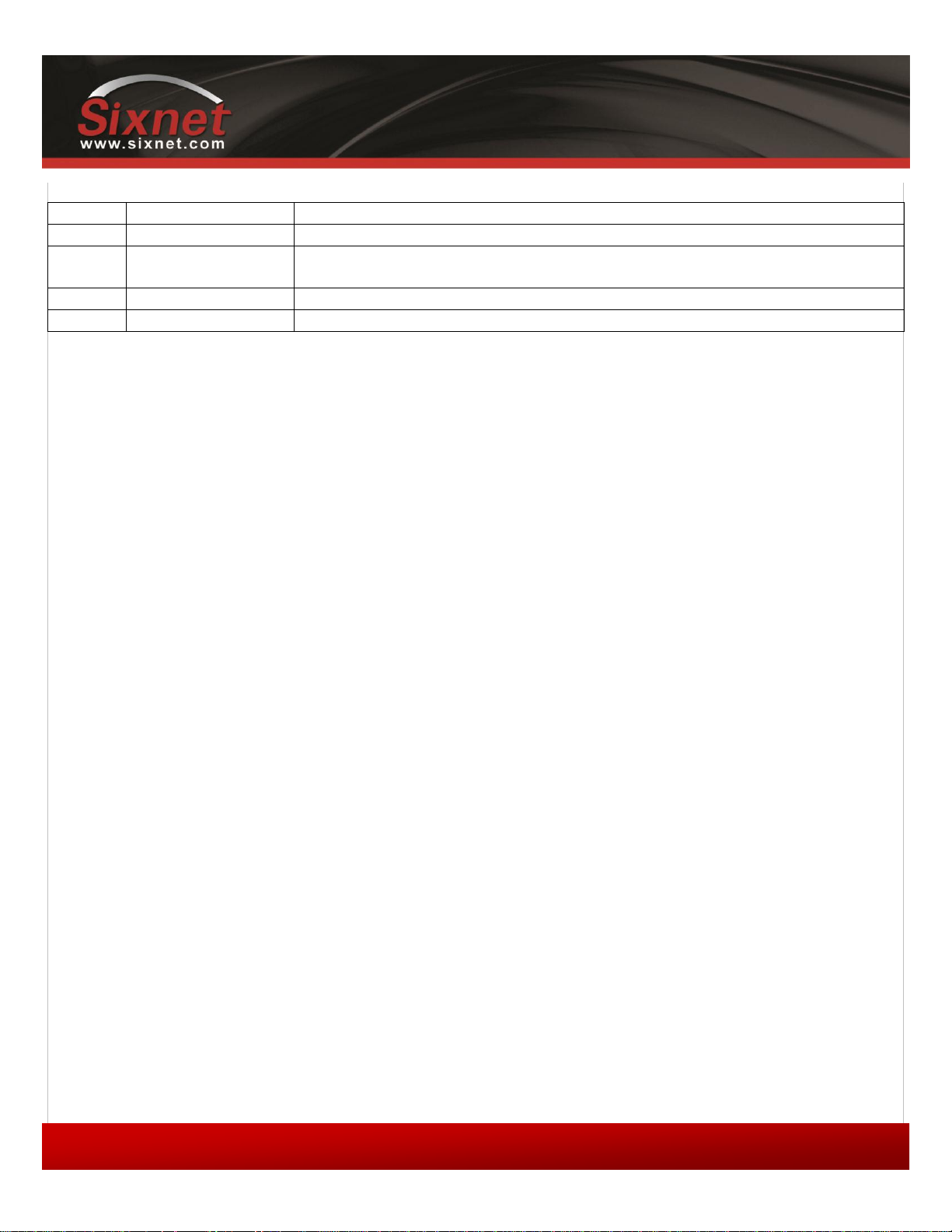
Change history
Version
Date
Description
1.11
November 2, 2011
Updated to cover BT-5x30 models
1.10
September 27, 2010
Update event and store and forward sections
Update environmental specifications
1.9
June 7, 2010
Add modem pictures Sixnet labels
1.8
March 30, 2010
Change document format
IndustrialPro™ and MobilityPro™ Gateway
User's Guide
Copyright © 2010 Sixnet LLC. All rights reserved.
Page 5

IndustrialPro™ and MobilityPro™ Gateway
5
1.11 – November 2, 2011
User's Guide
Table of content
1 Product Overview ...............................................................................................................................................8
1.1 Introduction ............................................................................................................................................................... 8
1.2 Modem features ...................................................................................................................................................... 10
1.3 Specifications ........................................................................................................................................................... 11
2 BlueVue Device Manager (BVDM) ...................................................................................................................... 22
2.1 Connecting to the modem ....................................................................................................................................... 23
2.2 Software overview ................................................................................................................................................... 25
3 AT Commands ................................................................................................................................................... 26
3.1 Access ....................................................................................................................................................................... 26
4 Activation & WAN Setup ................................................................................................................................... 27
4.1 Activation (CDMA modems only) ............................................................................................................................. 27
4.2 WAN Setup ............................................................................................................................................................... 28
5 LAN Setup ......................................................................................................................................................... 31
5.1 Ethernet and USB LAN ............................................................................................................................................. 31
5.2 LAN configuration .................................................................................................................................................... 31
5.3 Wireless(WiFi) .......................................................................................................................................................... 32
5.4 DHCP server ............................................................................................................................................................. 32
5.5 Dial-up Networking (DUN) over serial ..................................................................................................................... 32
6 IP Networking Features ..................................................................................................................................... 34
6.1 Port-forwarding ....................................................................................................................................................... 34
6.2 DMZ .......................................................................................................................................................................... 35
6.3 IP pass-through ........................................................................................................................................................ 36
6.4 Dynamic IP registration ............................................................................................................................................ 37
6.5 IP Security (IPSEC) .................................................................................................................................................... 38
6.6 Access Control List (ACL) .......................................................................................................................................... 38
6.7 Password protection ................................................................................................................................................ 38
7 Serial IP ............................................................................................................................................................. 40
8 GPS ................................................................................................................................................................... 41
8.1 GPS protocols ........................................................................................................................................................... 42
8.2 Odometer ................................................................................................................................................................. 42
8.3 Configuring the modem for GPS reporting .............................................................................................................. 42
9 I/O Management .............................................................................................................................................. 44
9.1 Digital Output control .............................................................................................................................................. 44
9.2 Digital Input state query .......................................................................................................................................... 44
9.3 Analog Input value query ......................................................................................................................................... 45
10 Event Reporting ........................................................................................................................................... 46
10.1 Events .................................................................................................................................................................. 46
10.2 Store and forward ................................................................................................................................................ 46
10.3 Actions ................................................................................................................................................................. 47
10.4 Reports ................................................................................................................................................................ 47
11 Hardware Installation .................................................................................................................................. 49
11.1 Mounting the BT-5x00v2 series modem ............................................................................................................. 49
Copyright © 2010 Sixnet LLC. All rights reserved.
Page 6

IndustrialPro™ and MobilityPro™ Gateway
6
1.11 – November 2, 2011
User's Guide
11.2 Mounting the BT-6000 series modem ................................................................................................................. 49
11.3 Cellular antenna................................................................................................................................................... 49
11.4 Ethernet cable ..................................................................................................................................................... 51
11.5 USB cable ............................................................................................................................................................. 51
11.6 Serial cable ........................................................................................................................................................... 51
11.7 Power source ....................................................................................................................................................... 51
12 Appendixes .................................................................................................................................................. 53
12.1 BlueVue Device Manager Troubleshooting ......................................................................................................... 53
12.2 Activation Troubleshooting ................................................................................................................................. 57
12.3 Troubleshooting .................................................................................................................................................. 60
12.4 Firmware Upgrades ............................................................................................................................................. 64
12.5 Sending AT Commands ........................................................................................................................................ 66
12.6 Dial-Up Networking in Windows ......................................................................................................................... 68
12.7 Warranty .............................................................................................................................................................. 70
12.8 Customer Support ............................................................................................................................................... 71
Copyright © 2010 Sixnet LLC. All rights reserved.
Page 7

IndustrialPro™ and MobilityPro™ Gateway
7
1.11 – November 2, 2011
User's Guide
FiguresFigure 1 - Router mode ............................................................................................................................................. 9
Figure 2 - IP pass-through mode ............................................................................................................................................. 9
Figure 3 – Serial connector (looking at back of modem) ...................................................................................................... 21
Figure 4 – The different ways to connect to a modem ......................................................................................................... 23
Figure 5 – Connecting to a remote modem .......................................................................................................................... 24
Figure 6 – Confirming the success of activation ................................................................................................................... 28
Figure 7 – Editing the account information .......................................................................................................................... 29
Figure 8 – Testing the connection ......................................................................................................................................... 30
Figure 9 – Default LAN IP configuration ................................................................................................................................ 31
Figure 10 – Sample modem configuration for communicating with a device that has the IP 10.127.0.17 ......................... 32
Figure 11 – Port-forwarding entries ...................................................................................................................................... 35
Figure 12 – Enabling DMZ ..................................................................................................................................................... 36
Figure 13 – Enabling IP passthrough ..................................................................................................................................... 36
Figure 14 – Enabling Dynamic IP Registration ...................................................................................................................... 38
Figure 15 – Enabling password protection ........................................................................................................................... 39
Figure 16 – Serial IP ............................................................................................................................................................... 40
Figure 17 – GPS configuration screen ................................................................................................................................... 41
Figure 18 – Modem with good signal strength ..................................................................................................................... 57
Figure 19 – Phone number being displayed on the Modem Diagnostic screen after activation ......................................... 58
Figure 20 – WAN IP being displayed after the modem successfully connects to the cellular network ............................... 59
Figure 21 – Upgrading the firmware ..................................................................................................................................... 65
Figure 22 – Creating a new connection in Windows XP ....................................................................................................... 68
TablesTable 1 – Modem features ....................................................................................................................................... 10
Table 2 – General specifications ........................................................................................................................................... 11
Table 3 - 4-pin Molex connector (BT-5000v2) ...................................................................................................................... 15
Table 4 - 4-pin Molex connector (BT-6x00)........................................................................................................................... 15
Table 5 - 4-pin screw terminal (BT-6xx1) .............................................................................................................................. 16
Table 6 – DC 2.5mm Barrel adapter (BT-6000) ..................................................................................................................... 16
Table 7 – Power consumption .............................................................................................................................................. 17
Table 8 – LEDs ....................................................................................................................................................................... 20
Table 9 – Reset button functions .......................................................................................................................................... 21
Table 10 – DHCP IP assignment ............................................................................................................................................ 31
Table 11 – NMEA messages information .............................................................................................................................. 42
Table 12 – dB loss per 100 feet of cable type ....................................................................................................................... 49
Copyright © 2010 Sixnet LLC. All rights reserved.
Page 8
IndustrialPro™ and MobilityPro™ Gateway
8
1.11 – November 2, 2011
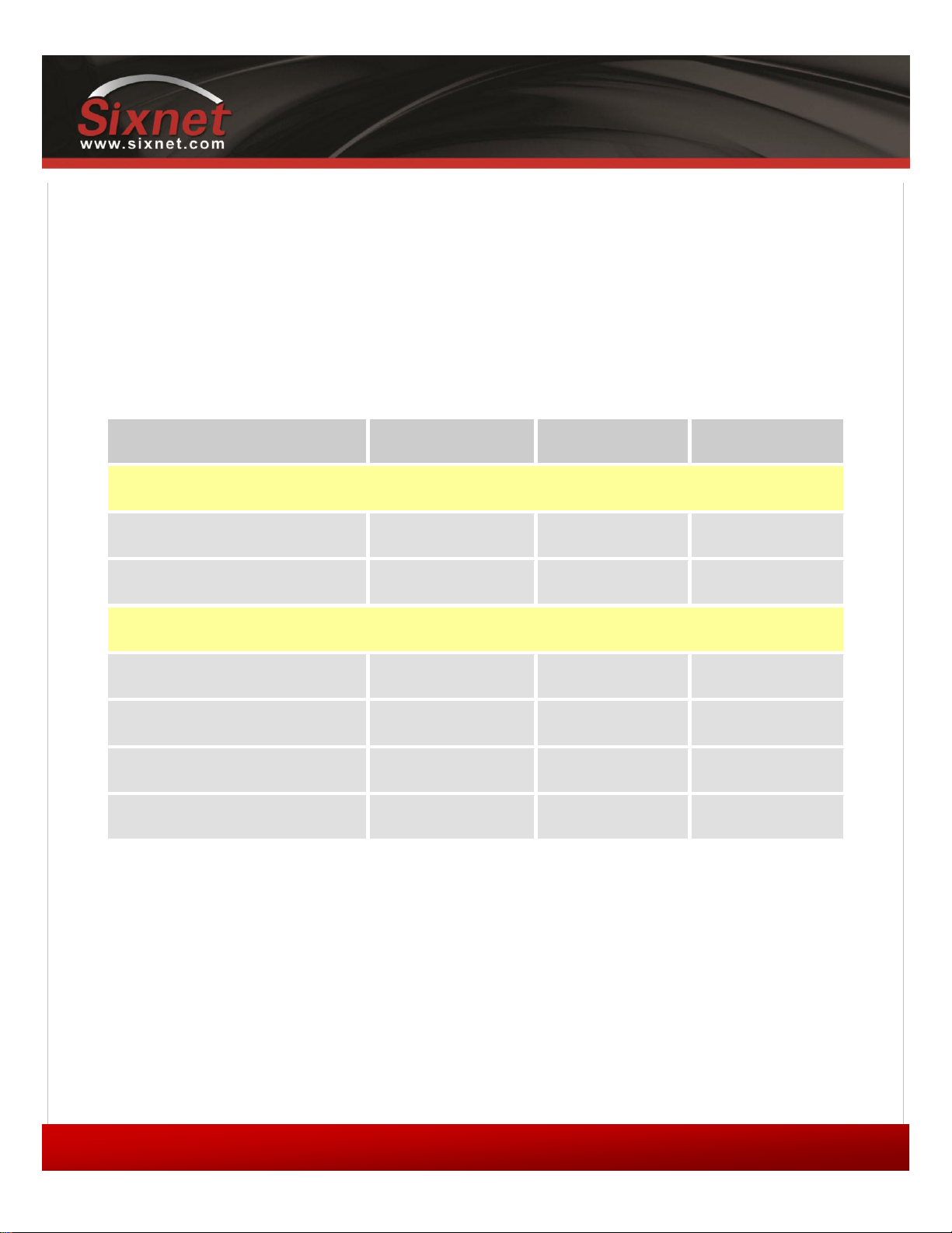
Type
CDMA EvDO.A
GSM EDGE
GSM HSPA
MobilityPro™ Gateway
Standalone GPS
BT-5600v2
BT-5800v2
Standalone GPS with Wi-Fi
BT-5630
BT5830
IndustrialPro™ Gateway
4-pin power connector
BT-6600
BT-6800
Screw-block power connector
BT-6601
BT-6401
BT-6801
PoE power input
BT-6601EB
BT-6401EB
BT-6801EB
Ethernet Switch
BT-6621
BT-6421
BT-6821
User's Guide
1 Product Overview
1.1 Introduction
The BlueTree 5000v2 and 6000 series modems are rugged cellular modems built to provide simple and reliable
communication over a CDMA or GSM cellular data networks. They are typically used in applications such as Public
Safety, Transportation, Vehicle Tracking, Telemetry, SCADA, Remote / Temporary Offices, Landline Replacement, and
WAN backup / Business Continuity.
The models covered by this document are:
The modem supports two operational modes: router mode, and IP pass-through mode.
1.1.1 Router mode
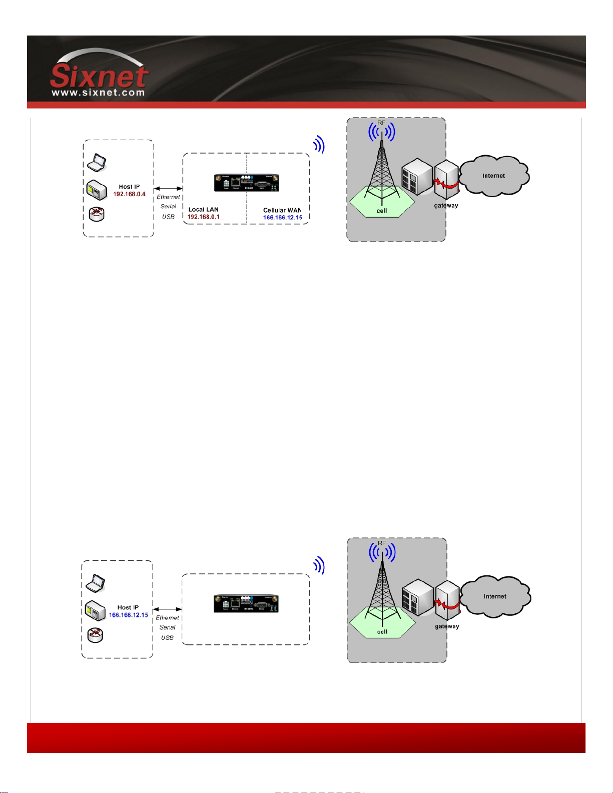
In Router mode, which is the default mode, the modem manages local and wireless connections independently, and is
capable of routing data packets back and forth between the two.
Copyright © 2010 Sixnet LLC. All rights reserved.
Page 9
IndustrialPro™ and MobilityPro™ Gateway
9
1.11 – November 2, 2011
Figure 1 - Router mode
The modem manages two connections at the same time, thus acting as a gateway/router:
Cellular WAN connection: This is the Wide Area Network connection to the cellular
network/Internet. The modem can be configured to automatically and autonomously
establish a packet data connection to the cellular carrier and acquire a WAN IP address.
User's Guide
LAN connection: This is the local connection between the modem and any device attached to
its Serial / Ethernet / USB ports. In the case of Ethernet and USB, the modem acts as a
DHCP server and assigns a private LAN IP address to the attached device.
The modem then routes packets back and forth between its WAN and LAN connections, and in turn allows the locally
attached device to communicate with computers or devices at a remote location.
1.1.2 IP pass-through mode
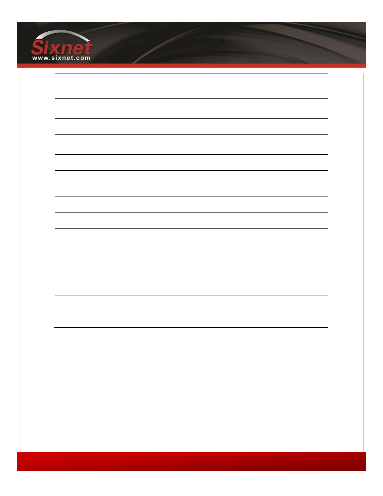
In IP pass-through mode, the modem assigns its WAN IP address directly to the attached host, thus becoming a fully
transparent actor in the communication process. The modem remains reachable through its reserved TCP and UDP ports
so that remote administration and configuration is still possible. Note that this mode allows only one IP address to be
assigned to the first connected device via DHCP (This configuration is not recommended for BT-6x21).
Figure 2 - IP pass-through mode
Copyright © 2010 Sixnet LLC. All rights reserved.
Page 10

10
1.11 – November 2, 2011
1.2 Modem features
3 different data
connection interfaces
Serial/RS-232/COM, Ethernet, and USB
Ethernet switch
Available on the BT-6x21 models only. These models have
an embedded 5-port Ethernet switch.
Power-over-Ethernet
Models ending in EB (BT-6x01EB) are models with built in
power sourcing. Power-over-Ethernet compatible devices
can be powered simply by connecting it to the modem’s
Ethernet port.
Autonomous &
persistent connection
management
Fully integrated TCP/IP protocols allow the modem to
connect autonomously to the packet network (Internet). This
feature enables capabilities such as: in-call diagnostic,
Serial-IP, stand-alone GPS, remote configuration and remote
firmware upgrades.
DHCP server
The modem’s DHCP server allows easy administration and
setup of the local network by automating IP address
assignment
IP pass-through
The modem can assign its WAN IP address to the attached
host, thus disabling the DHCP server’s Network Address
Translation. Even when performing pass-through, the
modem remains reachable for remote administration
through its reserved TCP ports.
IP security
The modem can be configured with up to 10 IPSEC tunnels
for increased security in communications.
In-call diagnostic
The user can get modem status information while in a data
call, without interrupting the data session
Serial IP
The modem can provide a reliable means of communication
with serial-only legacy devices. It can encapsulate data
coming from the serial port into a TCP or UDP packet and
send it to a remote server on the packet network or
Internet. It can decapsulate IP packets coming from the
network and send raw data to the serial port.
Remote configuration
The modem can be remotely configured or diagnosed using
BlueVue Device Manager or a terminal session
Remote firmware
upgrade
The modem’s firmware can be remotely upgraded using
BlueVue Device Manager software
Password protection
The modem’s configuration can be protected from tampering
by requesting the user to enter a password before the
existing modem configuration can be viewed or modified
IndustrialPro™ and MobilityPro™ Gateway
User's Guide
Table 1 – Modem features
Copyright © 2010 Sixnet LLC. All rights reserved.
Page 11

IndustrialPro™ and MobilityPro™ Gateway
11
1.11 – November 2, 2011
Integrated GPS receiver
BT-5000v2 models include a GPS receiver for Automatic
Vehicle Location (AVL). The modem can report this
positioning data locally to any of the local data interfaces
(serial, Ethernet, or Ethernet-over-USB), and/or remotely to
a predefined server (see stand-alone).
Standalone GPS
BT-5000v2 modems can be used for remote asset tracking
by sending GPS data to a remote server without the need for
a client application or computer connected to the modem.
Store and forward
If a unit loses its connection to the cellular network, the
event data being collected from I/O, GPS and other sources
will be stored in memory and automatically forwarded when
the connection is reestablished. This is available when using
TCP (with or without BEP ACK) or UDP (with BEP ACK only).
Inputs and outputs
Sensors can be connected to the I/O ports of the modem.
Depending on models, the modem is capable of monitoring
up to four digital inputs for any change in state, and up to
three analog inputs for changes in gradient data sources.
The modem also has up to three digital outputs that can be
used to remotely trigger relays.
The inputs and outputs can be used with the event reporting
protocol to allow automatic reports and triggers.
Event reporting
The modem can send a report to up to 10 destinations when
a user-defined event is triggered. Up to 30 events can be
defined based on I/O signals, GPS data, RF status. The
modem has an embedded event reporting protocol that
automatically formats the messages reported to the remote
server.
Mobile Originated
Management
The modem can connect to a remote server and perform
management actions (firmware upgrade, configuration
changes …). This feature uses Event Reporting.
Partner apps
The modem can host partner applications used for example
to report cellular traffic usage, vehicle diagnostics, alarms, …
Wireless interfaces
CDMA EvDO.A models
Dual-band CDMA2000 EVDO Rev. A (with diversity)
Backward compatible with 1xRTT and IS95
GSM EDGE Models
Quad-band 850/900/1800/1900 GSM
Backward compatible with Quad-band GPRS/UMTS
GSM HSPA Models
User's Guide
1.3 Specifications
1.3.1 General specifications
Table 2 – General specifications
Copyright © 2010 Sixnet LLC. All rights reserved.
Page 12
IndustrialPro™ and MobilityPro™ Gateway
12
1.11 – November 2, 2011
Quad-band 800/850/1900/2100 MHz WCDMA (with diversity)
HSDPA/HSUPA/HSPA
Backward compatible with GPRS/EDGE/UMTS
Peak data rates
Download: CDMA – 3.1Mbps / EDGE – 384 kbps / HSPA - 7 Mbps
Upload: CDMA - 1.8 Mbps / EDGE – 120 kbps / HSPA - 5.76 Mbps
Serial interface
1x RS-232 Serial DB9 115200bps
USB interface
BT-5000v2 series: 1x USB 2.0 type B
BT-6000 series: 1x USB 2.0 mini B
LED indicators
Power, WAN, Signal, RS232, GPS, Ethernet Link & Activity
Dimensions
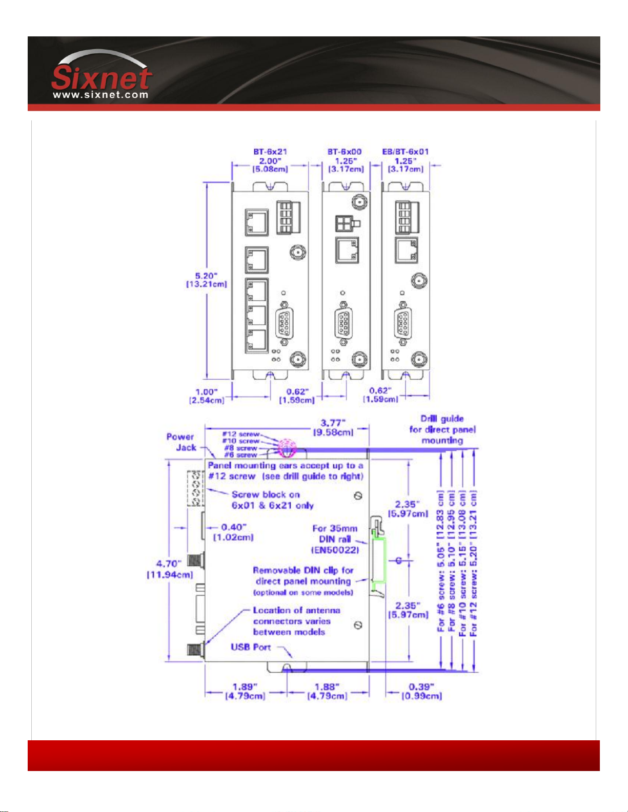
BT-6x0x: 120 x 96 x 32 mm (4.7 x 3.77 x 1.25"), 453g (1.0 lb)
BT-6x21: 120 x 96 x 51 mm (4.7 x 3.77 x 2.00"), 500g (1.1 lb)
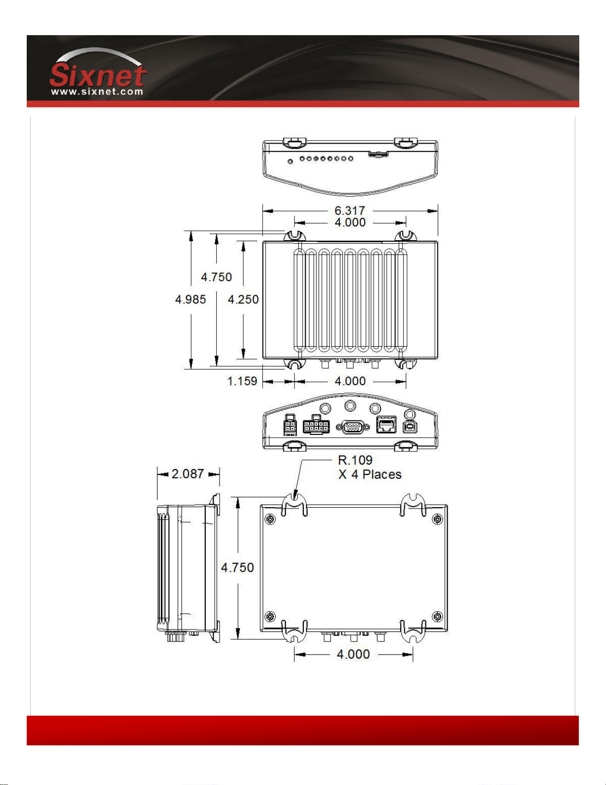
BT-5xx0v2: 159 x 127 x 53 mm (6.26 x 5.00 x 2.09”), 500g (1.1 lb)
Power Input
8 - 30 VDC (12 VDC nominal), Power over Ethernet on BT-6x01EB
Power consumption
See Table 6
Environmental
BT-5000v2 series
Operating Temp: -40 to +85°C (-40 to 185°F)
Shock & Vibration: MIL-STD 810F/202G
Humidity: 5 to 95% non-condensing
BT-6000 series
Operating Temp: -40 to +85°C (-40 to 185°F)
Shock & Vibration: IEC 60068-2-1/2/6/27/30, DNV 2.4 3.7/8/9, MIL-STD
810F/202G
Humidity: 5 to 95% non-condensing
Certification
Hazardous Locations - Class I, Div. 2, Groups A,B,C,D, UL1604
Electrical Safety - UL508/CSA22.2/14 (CUL)
EMC- FCC, part 15 and Industry Canada, ICES-003
PTCRB (GSM), CE, R&TTE
User's Guide
Copyright © 2010 Sixnet LLC. All rights reserved.
Page 13
IndustrialPro™ and MobilityPro™ Gateway
13
1.11 – November 2, 2011
1.3.2 Mechanical specifications BT-5xx0v2
User's Guide
Copyright © 2010 Sixnet LLC. All rights reserved.
Page 14
IndustrialPro™ and MobilityPro™ Gateway
14
1.11 – November 2, 2011
1.3.3 Mechanical specifications BT-6000
User's Guide
Copyright © 2010 Sixnet LLC. All rights reserved.
Page 15
IndustrialPro™ and MobilityPro™ Gateway
15
1.11 – November 2, 2011
O3 IGN
GND POS
Power connector
(facing modem)
Pin
Name
Description
1
GND
Ground
2
POS
Power supply input (8 to 30 VDC)
3
IGN
Ignition sense input (switches modem on or off)
4
O3
Digital Output 3
OUT IN
GND POS
Power connector
(facing modem)
Pin
Name
Description
1
GND
Ground
2
POS
Power supply input (8 to 30 VDC)
3
IN
Digital and analog input
4
OUT
Digital Output
User's Guide
1.3.4 Power specifications and consumption
Power is supplied to the modem via:
4-pin Molex connector for the BT-6x00 and BT-5x00v2 models
4-pin screw terminal for the BT-6x01, BT-6x01EB and BT-6x21 models
DC 2.5mm barrel plug for all BT-6000 models
Power over Ethernet for all BT-6x01EB models
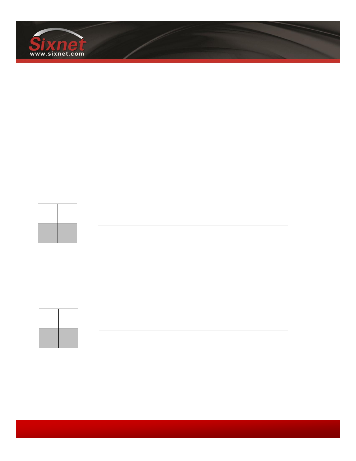
1.3.4.1 4-pin Molex Connector (BT-5000v2)
Power is supplied to the modem via the 4-pin Molex connector on the rear panel for BT-5x00 v2 models. The pins are
described as follows:
Table 3 - 4-pin Molex connector (BT-5000v2)
1.3.4.2 4-pin Molex Connector (BT-6x00)
Power is supplied to the modem via the 4-pin Molex connector on the front panel for the BT-6x00 models. The pins are
described as follows:
Copyright © 2010 Sixnet LLC. All rights reserved.
Table 4 - 4-pin Molex connector (BT-6x00)
Page 16
IndustrialPro™ and MobilityPro™ Gateway
16
1.11 – November 2, 2011
Power connector
(facing front)
Pin
Name
Description
1
GND
Ground
2
PWR+
Power supply input (8 to 30 VDC)
3
OUT
Digital output
4
IN
Digital and analog input
Power connector
(facing left side)
Pin
Name
Description
Sleeve
GND
Ground
Tip
PWR+
Power supply input (8 to 30 VDC)
User's Guide
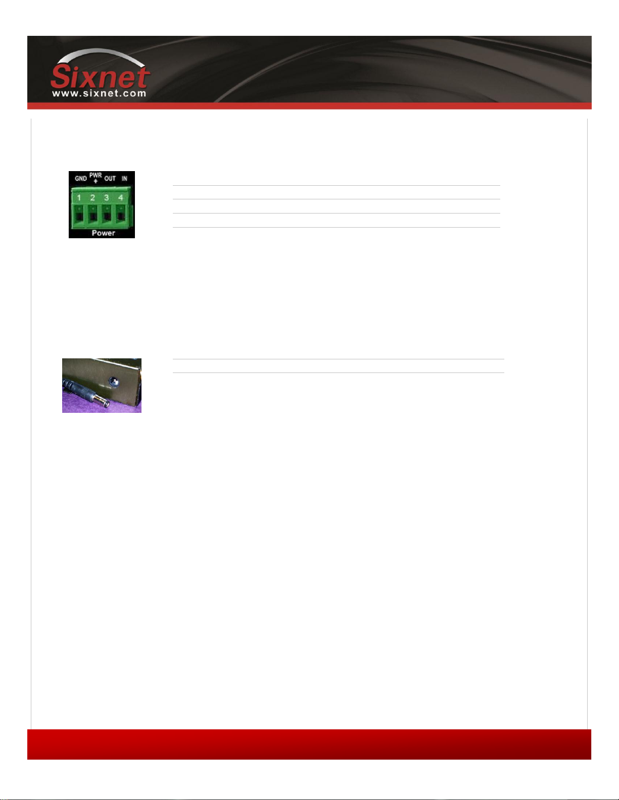
1.3.4.3 4-pin Screw Terminal (BT-6xx1)
Power is supplied to the modem via the 4-pin Screw Terminal on the front panel for the BT-6xx1 models. The pins are
described as follows:
Table 5 - 4-pin screw terminal (BT-6xx1)
1.3.4.4 DC 2.5mm Barrel Adapter
Power is supplied to the modem via the barrel adapter on the left side of all BT-6000 series modems. The contacts are
described as follows:
Table 6 – DC 2.5mm Barrel adapter (BT-6000)
WARNING:
DC 2.5mm Barrel Adapter shall not be used in hazardous locations.
Copyright © 2010 Sixnet LLC. All rights reserved.
Page 17
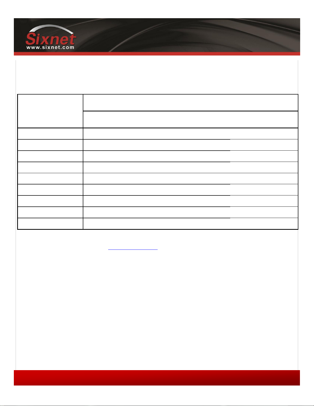
IndustrialPro™ and MobilityPro™ Gateway
17
1.11 – November 2, 2011
Model
Draw in mA (at 12 VDC)
Standby
Transmitting
Peaks
BT-5600v2
123
221
452
BT-5800v2
123
328
810
BT-6401
115
246
417
BT-6421
229
360
531
BT-660x
115
213
444
BT-6621
249
347
578
BT-6800
115
320
802
BT-680x
115
320
802
BT-6821
249
454
936
1.3.4.5 Power specification
Power input to the modem is protected against reverse polarity and over-voltage.
The modem’s power consumption is as follows:
Table 7 – Power consumption
User's Guide
Wiring instructions are provided in the Hardware Installation section.
All modems are equipped with protection for reversed polarity and power surges over 33 volts. The modems are
equipped with an internal 3 Amp fuse. When using the 4 pin Molex connector / power accessory cable supplied by
BlueTree Wireless, an extra 2 Amp fuse is also included (5600v2, 5800v2).
Copyright © 2010 Sixnet LLC. All rights reserved.
Page 18
IndustrialPro™ and MobilityPro™ Gateway
18
1.11 – November 2, 2011
Standalone GPS
With Wi-Fi(5x30 only)
BT-5xx0v2
BT-5600v2
BT-5800v2
BT-5630
BT-5830
4-pin power connector
BT-6x00
BT-6600
BT-6800
Screw-block power connector
BT-6x01
BT-6401*
BT-6601
BT-6801
Screw-block power connector
&
PoE power input
BT-6x01EB
BT-6401EB*
BT-6601EB
BT-6801EB
Ethernet Switch
BT-6x21
BT-6421*
BT-6621
BT-6821
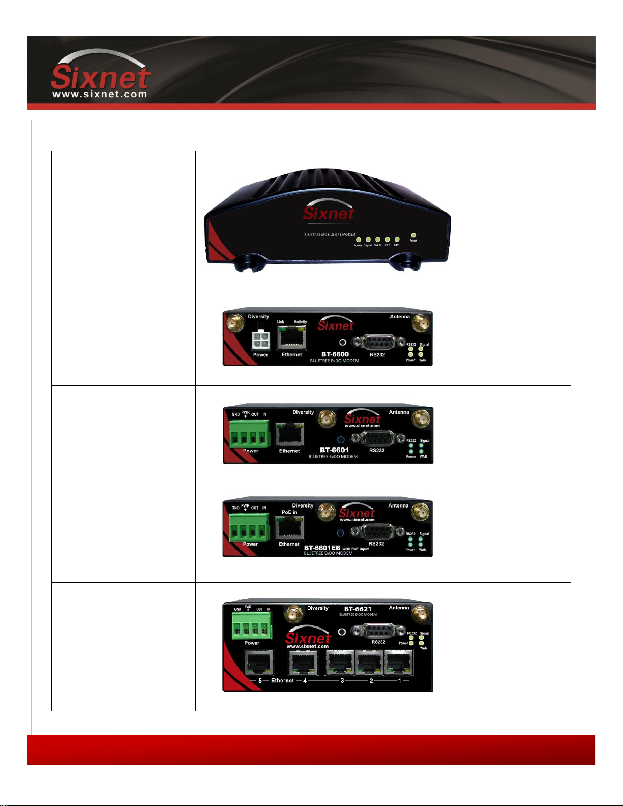
1.3.5 Modem views (Sixnet labels)
User's Guide
The BT-64xx series modems are not equipped with a diversity antenna connector
Copyright © 2010 Sixnet LLC. All rights reserved.
Page 19
IndustrialPro™ and MobilityPro™ Gateway
19
1.11 – November 2, 2011
Standalone GPS
BT-5x00v2
BT-5600v2
BT-5800v2
4-pin power connector
BT-6x00
BT-6600
BT-6800
Screw-block power connector
BT-6x01
BT-6401*
BT-6601
BT-6801
Screw-block power connector
&
PoE power input
BT-6x01EB
BT-6401EB*
BT-6601EB
BT-6801EB
Ethernet Switch
BT-6x21
BT-6421*
BT-6621
BT-6821
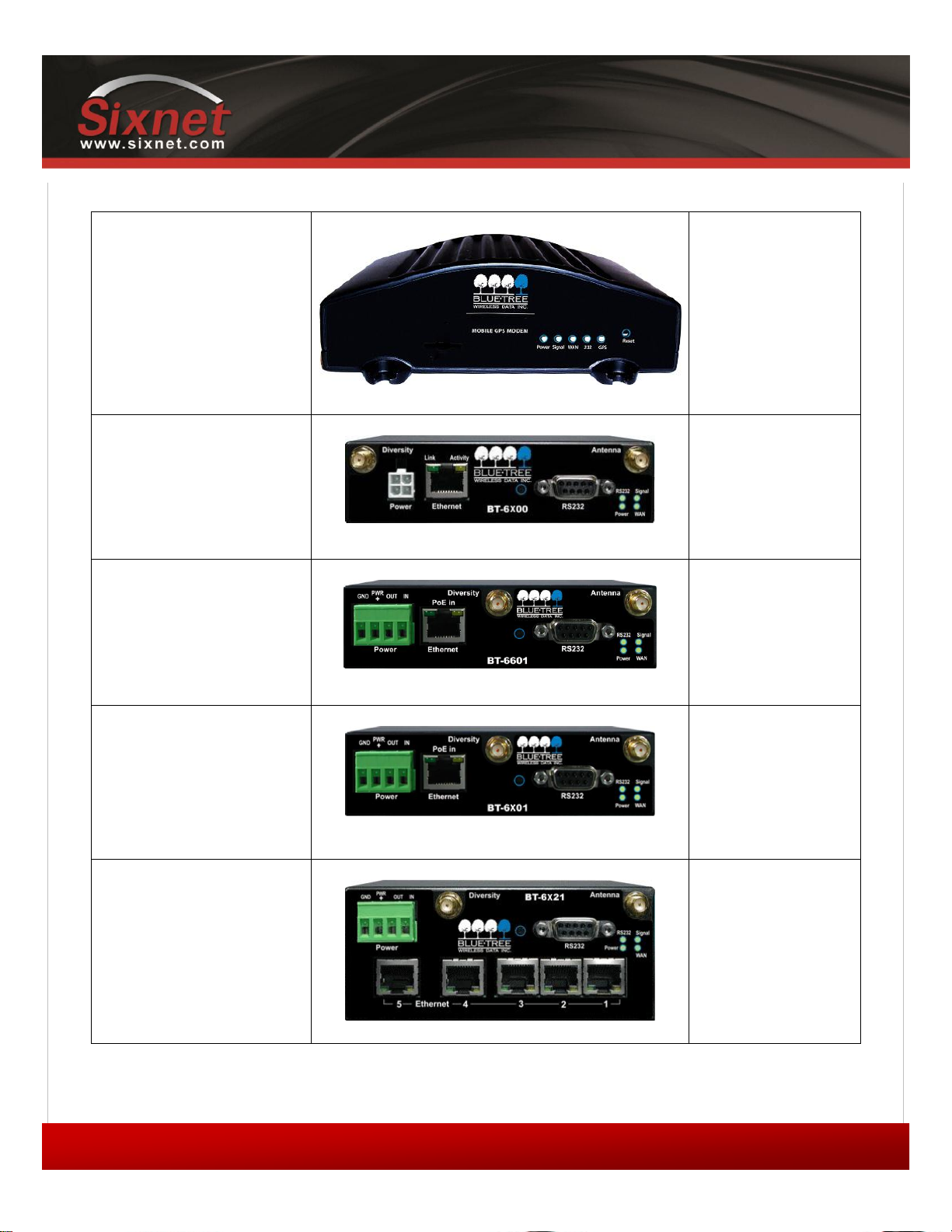
1.3.6 Modem views (BlueTree labels)
User's Guide
The BT-64xx series modems are not equipped with a diversity antenna connector
Copyright © 2010 Sixnet LLC. All rights reserved.
Page 20
IndustrialPro™ and MobilityPro™ Gateway
20
1.11 – November 2, 2011
LED
Status
Corresponding State
Power
OFF
Modem is powered off
ON
Modem is powered on
FLASH
Firmware error
Signal
OFF
No signal available or signal strength is below -100 dBm
ON
Excellent signal strength = greater than -69 dBm
FLASH
Fast: Every 300ms = -79 to -70 dBm
Medium: Every 600ms = -89 to -80 dBm
Slow: Every 1200ms = -99 to -90 dBm
WAN
OFF
Cellular connection is not established
ON
Cellular connection is established - no network data activity
FLASH
Cellular connection is established - with network data activity
RS232
OFF
Serial connection is not established
ON
Serial connection is established - no data activity with host
FLASH
Serial connection is established - with data activity with host
GPS
(BT-5x00v2)
OFF
No position fix available
ON
Position fix available
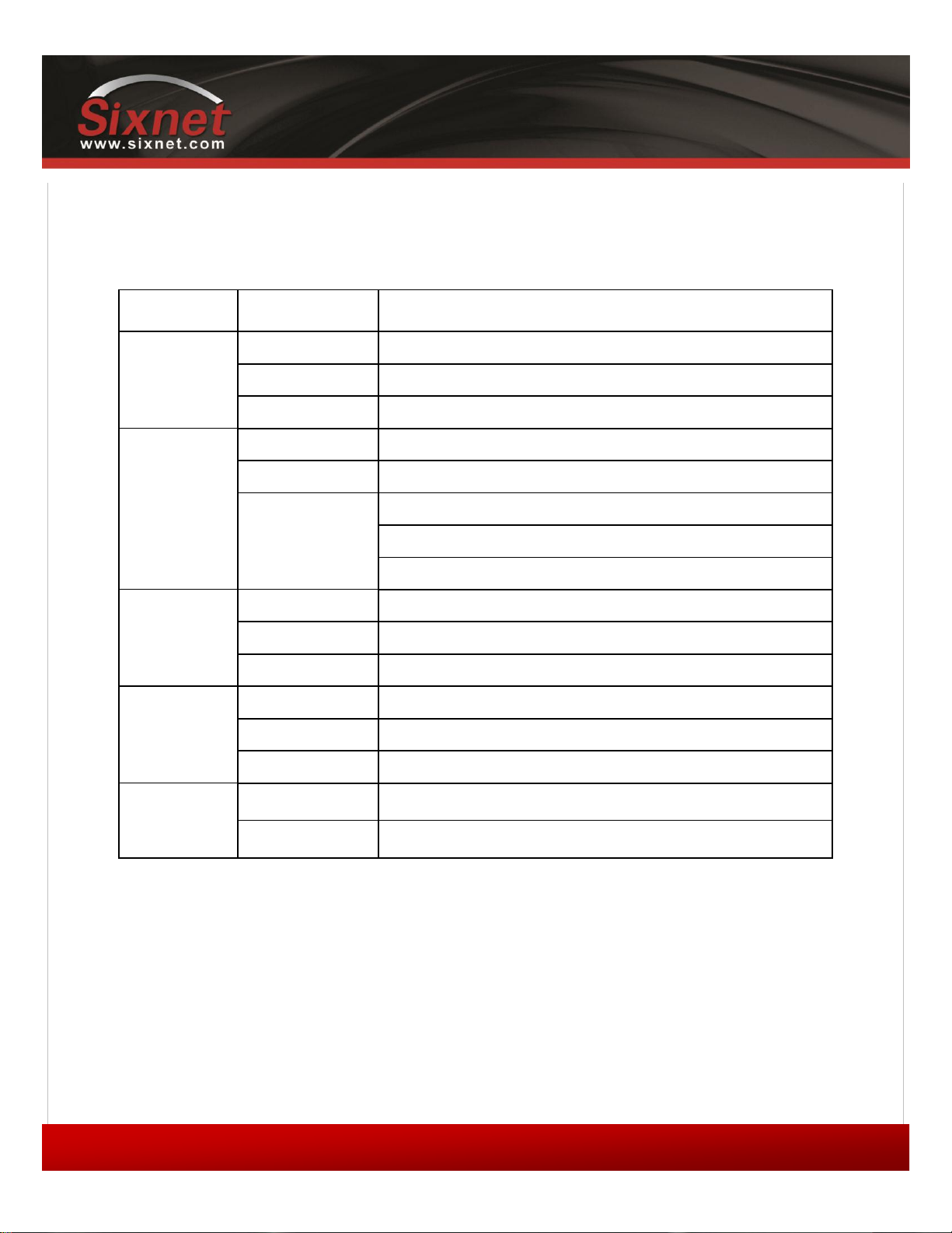
1.3.7 Indicators Lights (LED)
User's Guide
Table 8 – LEDs
1.3.8 Data Interface Specifications: Serial, Ethernet & USB
1.3.8.1 Ethernet Port
The modem's 10/100Mbps Ethernet port is compliant with the EIA-568 standard. The modem’s ports are autosensing so
they can be used with either a straight or crossover RJ45 cable to connect to host ports.
The BT-6x21 features a 5-port Ethernet switch allowing connectivity to multiple local devices.
Copyright © 2010 Sixnet LLC. All rights reserved.
Page 21
IndustrialPro™ and MobilityPro™ Gateway
21
1.11 – November 2, 2011
Mode
Pattern
Description
Hard reset
Press and hold for less than
3 seconds
Standard reboot
Factory restore
Press and hold between 3
and 10 seconds
RS232 LED flashes quickly
Overwrites user configuration with
the default factory settings
FW upgrade
Press and hold between 10
and 15 seconds
WAN LED flashes quickly
Puts the modem in advanced
firmware upgrade mode by restarting
the modem and running the
bootloader only. Do not use this
mode unless instructed to by
BlueTree Technical Support.
USB pass-through
Press and hold for longer
than 15 seconds
Signal LED flashes quickly
Puts the modem in main passthrough mode to the RF module,
allowing CCT provisioning and PST
support. Do not use this mode unless
instructed to by BlueTree Technical
Support.
User's Guide
1.3.8.2 USB Device Port
This is a USB 2.0 Device interface on a Type B (BT-5x00v2) or Mini B (BT-6xxx) connector. It offers Ethernet-over-USB
functionality using the RNDIS driver for Windows XP and Windows Vista Operating systems only. The BlueTree RNDIS
driver must be installed before the USB interface can be used. The driver is automatically installed with BlueTree Device
Manager or you can obtain the driver at www.sixnet.com and install it manually.
1.3.8.3 Serial Port (DB9)
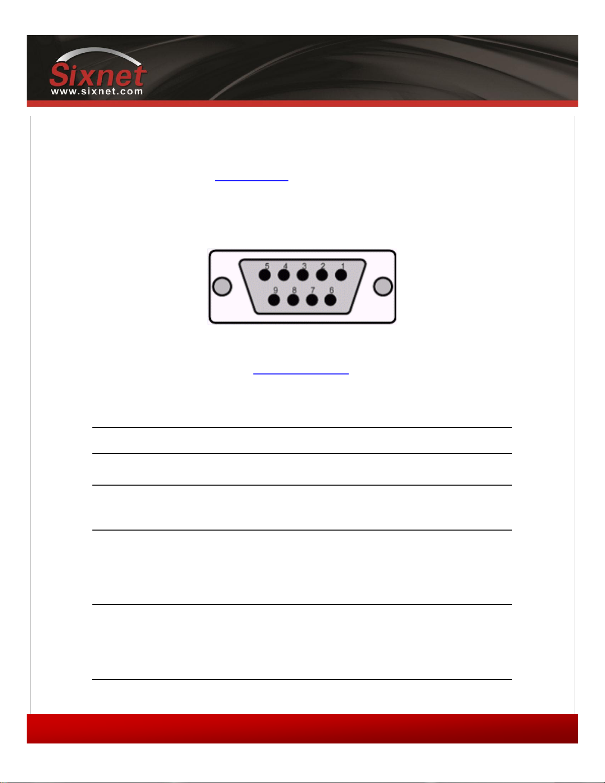
The modem’s serial port is an RS232 DCE, compliant with EIA-232 standard. The connector used is DB9 female and is
shown in the illustration below.
Figure 3 – Serial connector (looking at back of modem)
For further serial wiring information, refer to the Hardware Installation section.
1.3.9 RESET button functions
Table 9 – Reset button functions
Copyright © 2010 Sixnet LLC. All rights reserved.
Page 22

IndustrialPro™ and MobilityPro™ Gateway
22
1.11 – November 2, 2011
User's Guide
2 BlueVue Device Manager (BVDM)
The BlueTree BT-5000v2 and BT-6000 series modems can be configured using BlueVue Device Manager version 1.76 or
later. This software application is available as a free download at www.sixnet.com. Later sections of this guide will refer
to configuration options in this software. For more in-depth information on using BVDM, refer to the BlueVue Device
Manager User's Guide. It can be accessed from within BVDM itself by clicking the Help button, or downloaded separately
at www.sixnet.com.
BVDM is a Graphical User Interface for modem configuration and administration that allows the user to:
Activate the modem (program account information) for use on the cellular network
Register the modem on the cellular network (WAN Setup)
Configure operation parameters (such as LAN setup or GPS)
Monitor diagnostic and status information
Perform firmware upgrades to the modem
Copyright © 2010 Sixnet LLC. All rights reserved.
Page 23
IndustrialPro™ and MobilityPro™ Gateway
23
1.11 – November 2, 2011
User's Guide
2.1 Connecting to the modem
Should you run into any issues connecting to the modem, refer to the BlueVue Device Manager
Troubleshooting appendix.
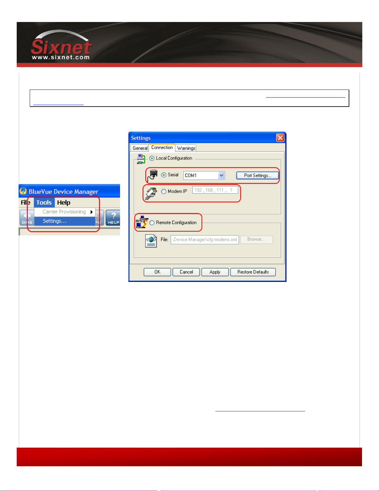
Click on Tools > Settings > Connection tab to select the interface your PC will use to connect to the modem.
Figure 4 – The different ways to connect to a modem
2.1.1 Using a serial cable:
1) Select Serial
2) Select the COM port in the dropdown list, then click OK
2.1.2 Using an Ethernet or USB cable:
3) Select Modem IP
4) Enter the appropriate modem IP then click OK. By default, the DHCP-assigned IPs will
be 192.168.0.1 for Ethernet and 192.168.111.1 for USB. If using USB, the BlueTree
RNDIS driver must be installed as explained in the Data Interface Specifications section.
Copyright © 2010 Sixnet LLC. All rights reserved.
Page 24
IndustrialPro™ and MobilityPro™ Gateway
24
1.11 – November 2, 2011
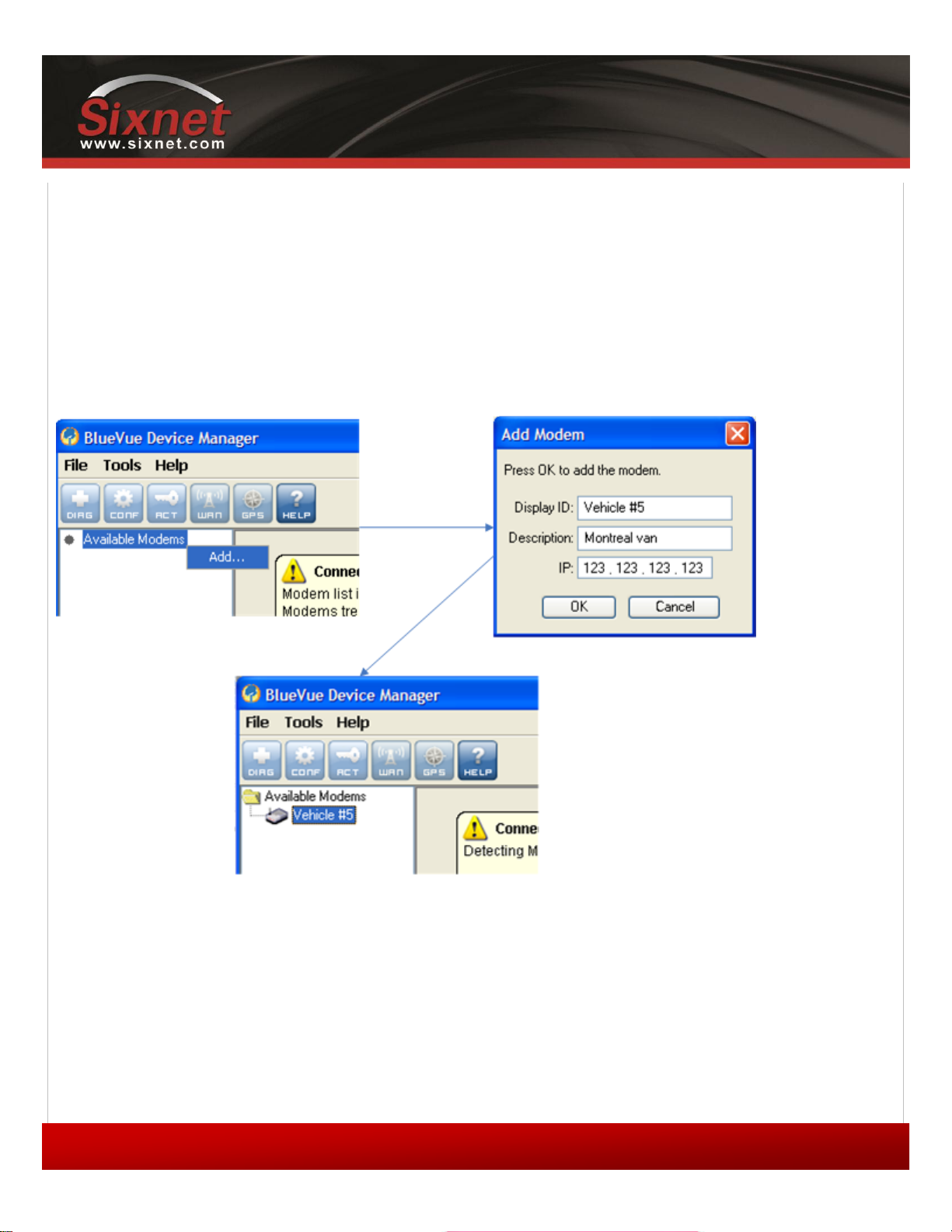
2.1.3 Connecting to a remote modem:
5) Select Remote Configuration and click OK. A new panel will open to the left of BlueVue
Device Manager.
6) Right-click Available Modems in the panel
7) Click Add…
8) Enter the modem’s information, then click OK. The description is optional.
9) The modem will be added to the list of Available Modems, which will be saved for easy
access in the future. Double-click the modem name in order to connect to it.
User's Guide
Figure 5 – Connecting to a remote modem
Copyright © 2010 Sixnet LLC. All rights reserved.
Page 25
25
1.11 – November 2, 2011
2.2 Software overview
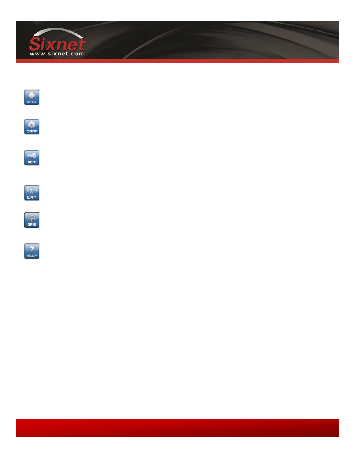
Modem Diagnostic
This screen displays various technical information pertaining to the modem's state.
Modem Configuration
This screen allows the user to configure the modem to suit the application
requirements.
Modem Activation
This screen is where the user performs cellular account activation so that the modem
may connect to the cellular network.
Modem WAN Settings
This screen allows the user to set the connection profile on the modem, such as the
user name and password of the account.
Modem GPS
This screen allows the user to configure the modem for basic GPS reporting (BT5x00v2 only).
Help
This button opens the BlueVue Device Manager User's Guide, a document that
explains every parameter of BlueVue Device Manager in detail.
IndustrialPro™ and MobilityPro™ Gateway
User's Guide
Copyright © 2010 Sixnet LLC. All rights reserved.
Page 26

IndustrialPro™ and MobilityPro™ Gateway
26
1.11 – November 2, 2011
User's Guide
3 AT Commands
The BlueTree BT-5000v2 and BT-6000 series modems can be configured and managed using AT commands.
AT is a command line interface allowing full control over the modem functionalities and diagnostics.
The AT commands are described in the AT command reference document available from www.sixnet.com.
AT commands allow for the creation of configuration scripts used to configure a fleet of modems with the same settings.
The AT command interface may be protected by a password.
3.1 Access
AT commands interface is accessible via:
- the modem serial port (when not in DUN, Serial IP or Serial pass-through). The default serial settings are:
o 115200 bauds
o 8 bits data
o no parity
o one stop bit
o hardware flow control
- a TCP/IP connection to port 6070 over:
o LAN Ethernet
o LAN USB
o WAN (remote access)
The modem accepts up to two concurrent TCP/IP connections to port 6070 (in addition to the serial port). When an
additional connection is attempted, the idlest connection is dropped.
A terminal emulation application such as Hyperterminal, PuTTY or teraterm is required. Terminal emulation applications
can be freely downloaded from the internet. For TCP/IP access, terminal emulation software or a telnet client software
can be used.
Please refer to 12.5Sending AT Commands for more details.
Copyright © 2010 Sixnet LLC. All rights reserved.
Page 27
IndustrialPro™ and MobilityPro™ Gateway
27
1.11 – November 2, 2011
User's Guide
4 Activation & WAN Setup
4.1 Activation (CDMA modems only)
A modem must be activated and configured before it can be used on the cellular network. The steps below outline how
to activate a modem. To configure the modem to connect to the wireless network after activation has been performed,
skip to the next section.
4.1.1 Obtaining a cellular account for the modem
Contact a cellular service provider or cellular dealer and request a CDMA account with the packet data service option
for 1xRTT, 1xEV-DO, or 1xEV-DO Rev. A. The provider will require the Electronic Serial Number (ESN) of the modem. The
ESN is located on the label under the modem as well as on the modem’s packaging box.
The cellular service provider will then provide the information required to activate the modem.
IMPORTANT
Ask your cellular service provider whether the carrier blocks incoming connections. If they do, you
will be unable to communicate with the modem remotely unless you ask the service provider to
allow incoming connections to your application’s TCP and UDP ports. If possible, ask them to open
the following ports as well: TCP 20 and TCP 21 (used for firmware upgrades), TCP 5070 (used by
BlueVue Device Manager), and TCP 6070 and 6073 (used for AT command configuration and
troubleshooting).
4.1.2 Programming the account information into the modem
The steps required to program the account information into the modem are unique to each carrier. The Quick Start
Guide booklet included in the modem package contains a step-by-step walkthrough for activating the modem. The latest
version of the Quick Start Guide is also available for download at http://www.sixnet.com/.
4.1.3 Confirming the success of activation
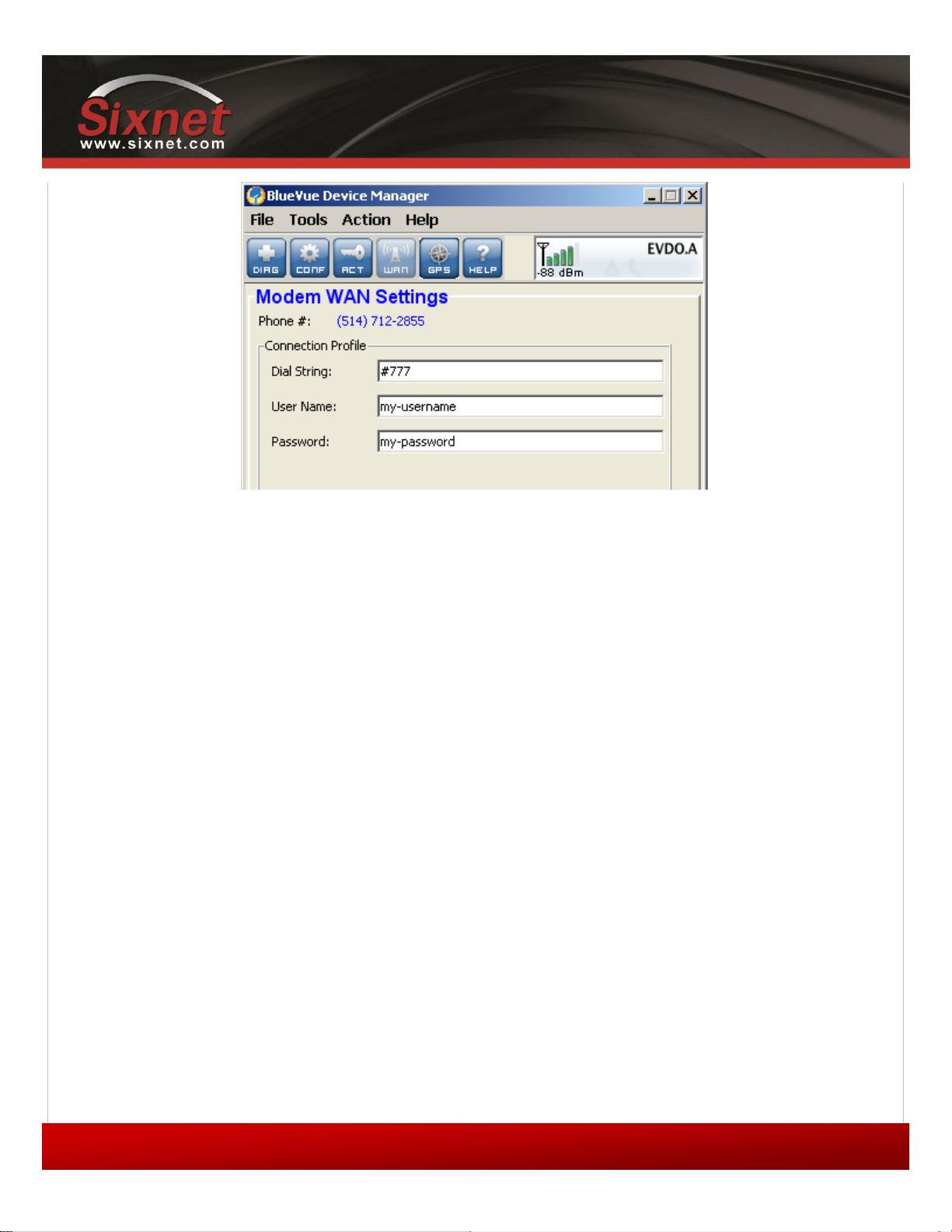
Once the activation process above is complete, navigate to WAN (WAN Settings). The modem’s phone number should
be displayed at the top left as shown in Figure 6.
Copyright © 2010 Sixnet LLC. All rights reserved.
Page 28
IndustrialPro™ and MobilityPro™ Gateway
28
1.11 – November 2, 2011
User's Guide
Figure 6 – Confirming the success of activation
4.2 WAN Setup
After the modem has been activated, it must be configured in order to authenticate for use with the cellular network.
4.2.1 Enter the account information
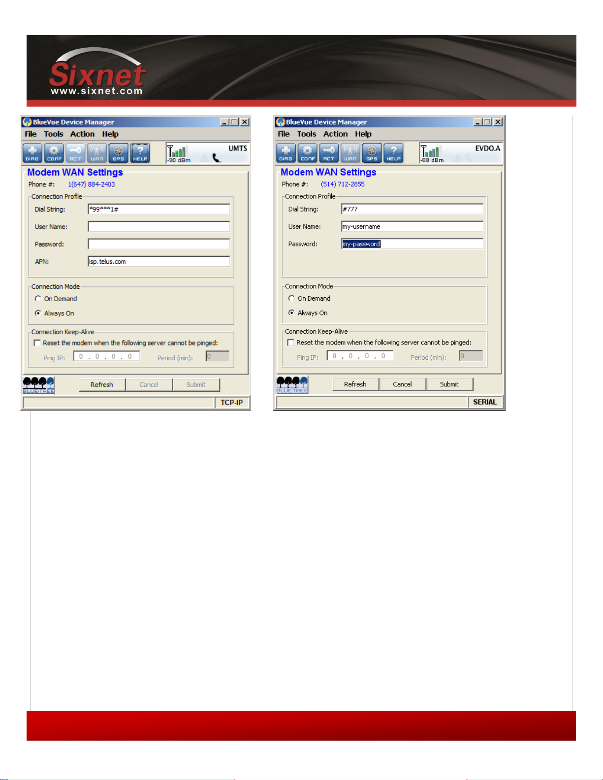
Navigate to WAN (WAN Settings) to configure the WAN connection once the modem has been activated.
Copyright © 2010 Sixnet LLC. All rights reserved.
Page 29
IndustrialPro™ and MobilityPro™ Gateway
29
1.11 – November 2, 2011
User's Guide
Figure 7 – Editing the account information
1) Enter the Dial String:
#777 for CDMA modems
*99# for HSPA modems (Bell Mobility and Telus)
*99***1# for other GSM modems (EDGE and HSPA)
2) Enter the User Name and Password if provided by your cellular carrier otherwise, leave
them empty.
3) Select Always On or On Demand (explained below) depending on the desired connection
initiation behavior.
4) Enter APN information that was provided to you if you are using a GSM modem. The APN
field is only shown when BVDM is connected to a GSM (EDGE and HSPA) modem.
When the modem is set to Always On, it will attempt to maintain a permanent connection to the cellular network on its
own. Most applications will require the modem to be remotely accessible at any time, and will require the modem to be
set to Always On.
When the modem is set to On Demand, the modem does not connect to the cellular network unless told to by the
attached terminal. If disconnected from the cellular network, it will not attempt to reconnect. The most common On
Copyright © 2010 Sixnet LLC. All rights reserved.
Page 30
IndustrialPro™ and MobilityPro™ Gateway
30
1.11 – November 2, 2011
User's Guide
Demand scenario is when using the serial port in order to establish a PPP session through a Dial-Up Networking (DUN)
connection.
Unless you are sure the modem should be set to On Demand, the modem should be set to Always On.
4.2.2 Testing the connection
Once you've finished entering the settings, and once a connection is established (depending on the connection initiation
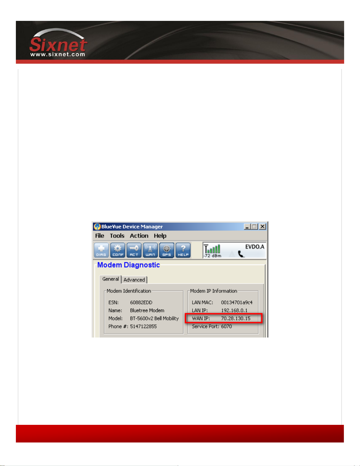
behavior described above), navigate to DIAG (Modem Diagnostic) and click on Refresh button: the modem’s WAN IP
should be displayed as outlined in Figure 8. This is the IP address that has been assigned to the modem by the cellular
carrier. At this time, the modem’s WAN light will stay on as long as the connection is maintained.
Notes:
HSPA/EDGE: no activation is required since all the connection and network information is contained in
the SIM card.
HSPA/EDGE: Please note that the modem needs to be reset after a SIM card is inserted.
Please note that some carriers prefer to have the modem phone number hidden. In this case, the
modem phone number is not displayed in BVDM.
Figure 8 – Testing the connection
Copyright © 2010 Sixnet LLC. All rights reserved.
Page 31
IndustrialPro™ and MobilityPro™ Gateway
31
1.11 – November 2, 2011
Modem IP
Host IP
Ethernet
192.168.0.1
192.168.0.4
USB
192.168.111.1
192.168.111.20
User's Guide
5 LAN Setup
5.1 Ethernet and USB LAN
Computers and devices that use the modem’s Ethernet and USB connectivity experience much higher transfer speeds
and they employ all the benefits of TCP/IP communication.
5.2 LAN configuration
Whether an Ethernet or USB cable is used, it is essential that both the modem and the attached device be within the
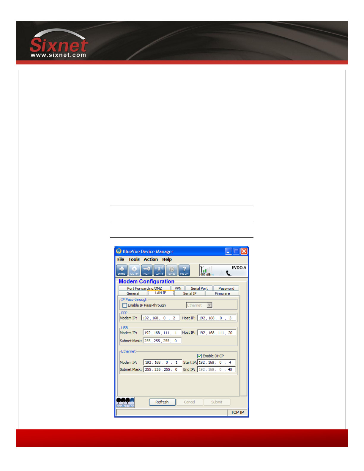
same LAN subnet for IP communication to take place. By default, the modem has a DHCP server running, which will
initially assign the following IP address to the attached device (providing the device is set to use DHCP):
Table 10 – DHCP IP assignment
Copyright © 2010 Sixnet LLC. All rights reserved.
Figure 9 – Default LAN IP configuration
Page 32
IndustrialPro™ and MobilityPro™ Gateway
32
1.11 – November 2, 2011
User's Guide
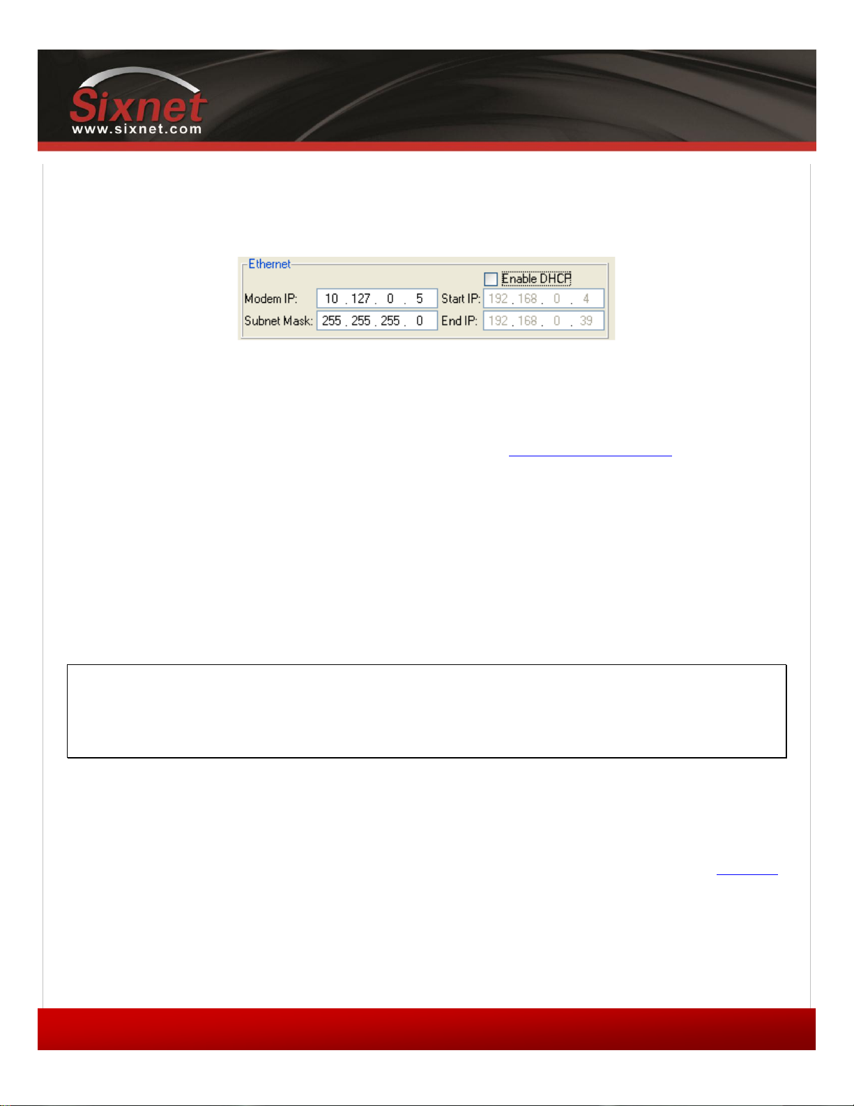
If the attached device must use a specific (static) IP, then the modem's LAN configuration must be changed so that the
modem's IP lies in the same subnet as the device. Navigate to CONF (Modem Configuration) > LAN IP and change the
parameters under Ethernet or USB.
Figure 10 – Sample modem configuration for communicating with a device that has
the IP 10.127.0.17
5.3 Wireless(WiFi)
All configuration of the integrated Wi-Fi feature in the BT-5x30 is done via AT commands only. For configuration of this
feature please refer to the separate AT Command Reference, available at http://support.sixnet.com
5.4 DHCP server
As mentioned above, the modem has a DHCP server which automatically assigns an IP to the attached device. If an
Ethernet hub or switch is connected to the modem’s Ethernet port, the modem will assign an IP address to each device
connected to the hub or switch, for a maximum of 254 devices, provided the devices are configured as DHCP clients
(“Dynamic” or “Automatic” IP configuration). The DHCP server can be configured or turned off in CONF (Modem
Configuration) > LAN IP as shown above.
5.5 Dial-up Networking (DUN) over serial
Note:
Regardless of the modem type, using a serial cable will cap the bandwidth at 115200 kbps. The
serial port will be a bottleneck in terms of performance, as it will reduce the data throughput
considerably to less than 3% of its maximum potential. Whenever possible, use an Ethernet or USB
connection to take full advantage of throughput.
Some terminals do not have RJ45 Ethernet or USB connectors and require using a DB9 RS232 standard serial connector
to interface with the modem.
If the attached device is not programmable (smart), then you cannot use DUN, and will
have to use the Serial IP feature to communicate with the device. Refer to the Serial IP
section for details.
If the modem will be used with a programmable device that can make PPP connections,
then refer to that device's documentation to create the dial-up session. The phone number
to dial will be the same as the one programmed in the Dial String of the WAN setup. The
username and password, if any, will be those provided by your cellular service provider.
Copyright © 2010 Sixnet LLC. All rights reserved.
Page 33
33
1.11 – November 2, 2011
IndustrialPro™ and MobilityPro™ Gateway
User's Guide
If the modem is used with a PC making a PPP connection, then a standard modem driver on
the COM port to which the modem is physically connected must be installed, and then a
dial-up connection running on that driver must be created. This dial-up connection will dial
the modem so that a PPP session is established between modem and PC. Meanwhile, the
modem will make a PPP session of its own to connect to the network. For a walkthrough on
creating a DUN connection in Windows, refer to the Dial-Up Networking in Windows
appendix.
Copyright © 2010 Sixnet LLC. All rights reserved.
Page 34
IndustrialPro™ and MobilityPro™ Gateway
34
1.11 – November 2, 2011
User's Guide
6 IP Networking Features
As mentioned previously, the modem acquires an external public or private IP address (WAN IP, or Wide Area Network
IP) from the cellular network upon establishing a connection. A remote user can communicate with the modem or a host
behind the modem; however the appropriate port-forwarding, DMZ or IP pass-through and LAN IP configuration must
be set on the modem. Read on for a description of each configuration option.
Some carriers disable remote access as a security measure. If you are certain that the modem is
on the cellular network (i.e., it has acquired a WAN IP) and that the local network is set up
properly, but you cannot reach the modem remotely, confirm with the carrier that incoming IP data
traffic is allowed on the required TCP or UDP port. Read the BlueVue Device Manager
Troubleshooting section for more details.
6.1 Port-forwarding
Since the modem is a network address translation (NAT) enabled router, the remote computer connecting to the
modem’s cellular WAN IP cannot access devices/servers on the modem’s LAN if the modem is not specifically configured
to forward the appropriate ports to the LAN devices/servers. Port-forwarding, or tunneling, is the act of relaying an
incoming packet to one or more local destinations depending on the port(s) through which the packet came.
The main use of port-forwarding is to allow an external user to reach a port on a private IP address from the outside via
a NAT. This allows remote computers to connect to a specific computer within a private LAN, depending on the port
used to connect.
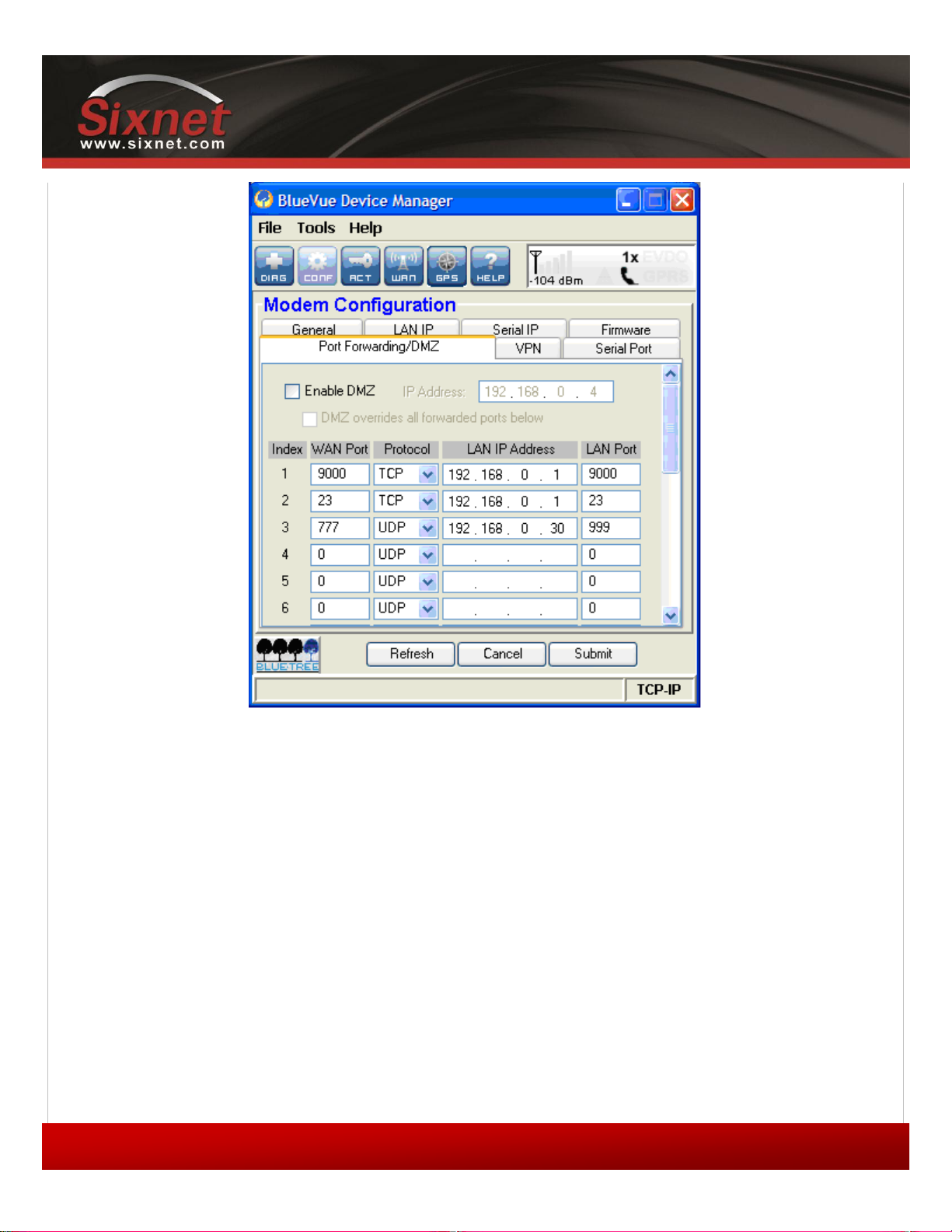
To set up the modem's port forwarding rules, navigate to CONF (Modem Configuration) > Port Forwarding/DMZ.
Copyright © 2010 Sixnet LLC. All rights reserved.
Page 35
IndustrialPro™ and MobilityPro™ Gateway
35
1.11 – November 2, 2011
User's Guide
Figure 11 – Port-forwarding entries
The WAN Port is the destination port number used by the remote computer and the LAN Port is where the data is
forwarded to. Typically the WAN port and LAN port are the same; however any port can be used on the WAN side, as
long as it points towards the correct LAN port. Select the appropriate protocol (TCP or UDP), and submit the new
settings.
6.2 DMZ
This feature, when enabled, instructs the modem to port-forward all incoming traffic to a single IP destination on the
LAN. An exception will be made for traffic coming on the ports designated by the port-forwarding rules (this would be
ports 9000, 23, and 777 in Figure 11). This exception can be overridden by checking the “DMZ overrides all forwarded
ports below” checkbox.
Copyright © 2010 Sixnet LLC. All rights reserved.
Page 36
IndustrialPro™ and MobilityPro™ Gateway
36
1.11 – November 2, 2011
Router Mode
IP Pass-through Mode
Host IP Address
192.168.0.4
aaa.bbb.ccc.ddd (WAN Address)
Modem IP Address
192.168.0.1
aaa.bbb.ccc.1 or .2(if ddd=1)
User's Guide
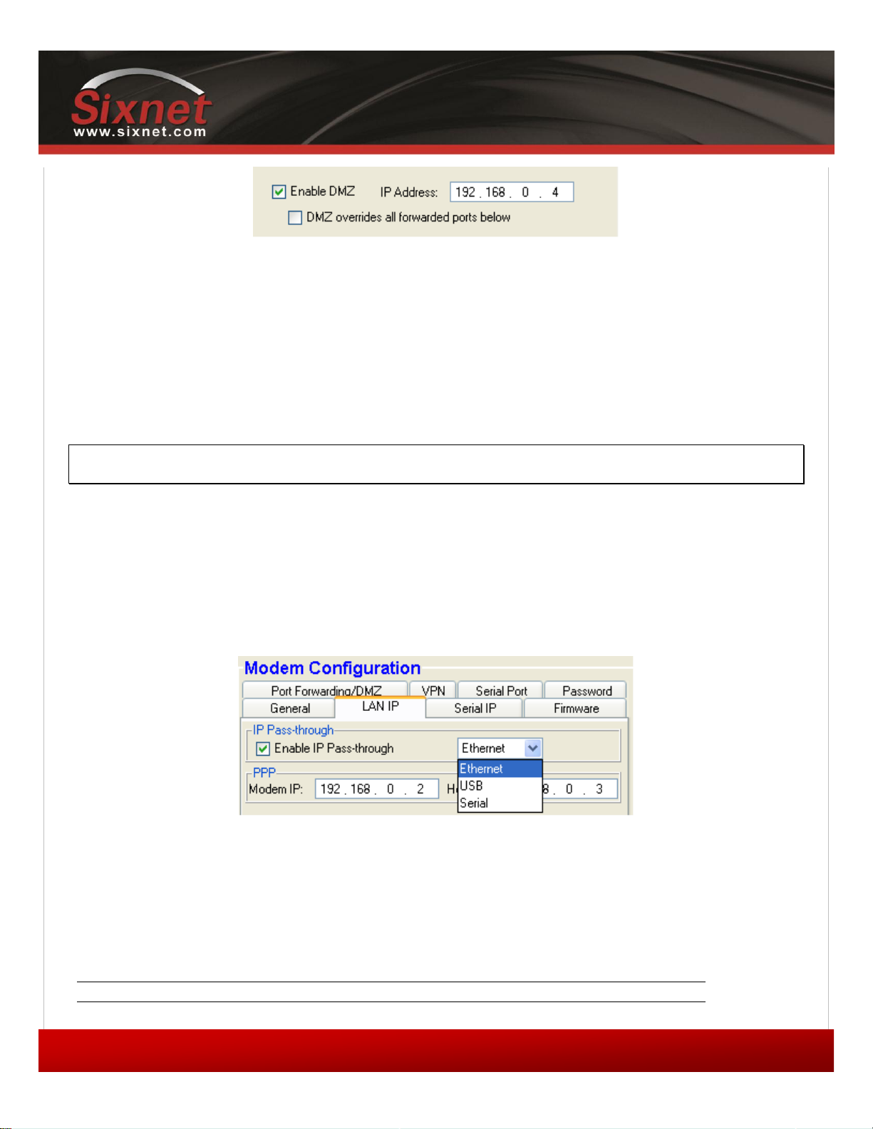
Figure 12 – Enabling DMZ
DMZ is ideal in situations where there is already a server on the LAN that handles port-forwarding, as it avoids having to
re-program all the port-forwarding rules into the modem. It is also practical when the user does not know which ports
his local device listens on, and just wants everything to work with minimal configuration.
DMZ can be enabled at CONF (Modem Configuration) > Port Forwarding/DMZ.
6.3 IP pass-through
Note
When IP pass-through is enabled, both port-forwarding and DMZ are disabled.
When this feature is enabled, the modem will disable NAT and assign its WAN IP address to the attached host. This will
solve VPN authentication issues that are caused by NAT. The modem will remain reachable though its reserved TCP and
UDP ports.
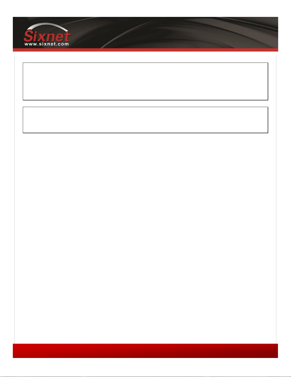
To enable IP pass-through, navigate to CONF (Modem Configuration) > LAN IP and select the data interface to perform
pass-through on, then check the “Enable IP Pass-through” checkbox.
If the host is attached to the modem via an Ethernet cable, then the host must have DHCP enabled (i.e., it should be
perform automatic IP negotiation instead of using a pre-defined static IP). If the host is attached to the modem via a
serial cable, IP pass-through will only activate when the host creates a PPP session to the modem.
Once IP pass-through is enabled the default IP settings will alter as follows:
Copyright © 2010 Sixnet LLC. All rights reserved.
Figure 13 – Enabling IP passthrough
Page 37
IndustrialPro™ and MobilityPro™ Gateway
37
1.11 – November 2, 2011
User's Guide
Note
Enabling or disabling IP pass-through reset the concerned interfaces and may stop established
connections (e.g. BlueVue Device Manager).
To work around this issue, do not enable/disable IP pass-through on the interface used for the
device configuration.
Note
This mode allows only one IP address to be assigned to the first connected device via DHCP (This
configuration is not recommended for BT-6x21).
6.4 Dynamic IP registration
This feature allows the modem to report a message to a user-configurable IP address every time its WAN IP address
changes.
It is useful when the cellular account is associated with a dynamic IP address. Since the WAN IP address will be changing
regularly, it will be impossible for the user to know which WAN IP address is assigned to the modem. With Dynamic IP
Registration enabled, the modem will notify a remote server of the new WAN IP address as well as the modem’s ESN in
hexadecimal format. The IP Registration packet can be sent using either TCP or UDP.
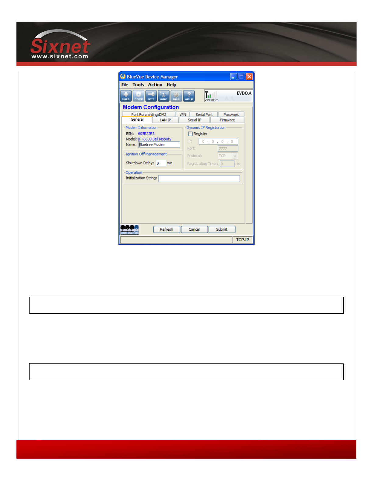
To configure Dynamic IP Registration, navigate to CONF (Modem Configuration) > General, and set the destination IP
address and port. The registration timer is a value (in minutes) that controls how often the modem should report its IP
to the server. If it is set to zero, the modem will report its WAN IP address upon boot-up or upon acquiring a new IP
address from the cellular carrier after losing the cellular connection. If it is set to a value between 1 and 65535, then it
will report its ESN and WAN IP regularly at the specified interval.
Copyright © 2010 Sixnet LLC. All rights reserved.
Page 38
IndustrialPro™ and MobilityPro™ Gateway
38
1.11 – November 2, 2011
User's Guide
Figure 14 – Enabling Dynamic IP Registration
6.5 IP Security (IPSEC)
The modem supports up to 10 IPSEC VPN tunnels used to secure communications with remote servers.
Please refer to the "Getting Started with IPSEC" application notes for further details.
Note
IP Security can only be configured and managed via AT commands.
6.6 Access Control List (ACL)
The modem can be configured with Access Control List to prevent un-authorized incoming IP traffic.
Please refer to the "Getting Started with ACL" application notes for further details.
Note
ACL cannot only be configured and managed via AT commands.
6.7 Password protection
This feature allows administrators to restrict unauthorized users from configuring the modem by requiring a password
whenever the modem’s configuration ports are accessed.
Copyright © 2010 Sixnet LLC. All rights reserved.
Page 39
IndustrialPro™ and MobilityPro™ Gateway
39
1.11 – November 2, 2011
User's Guide
To enable password protection:
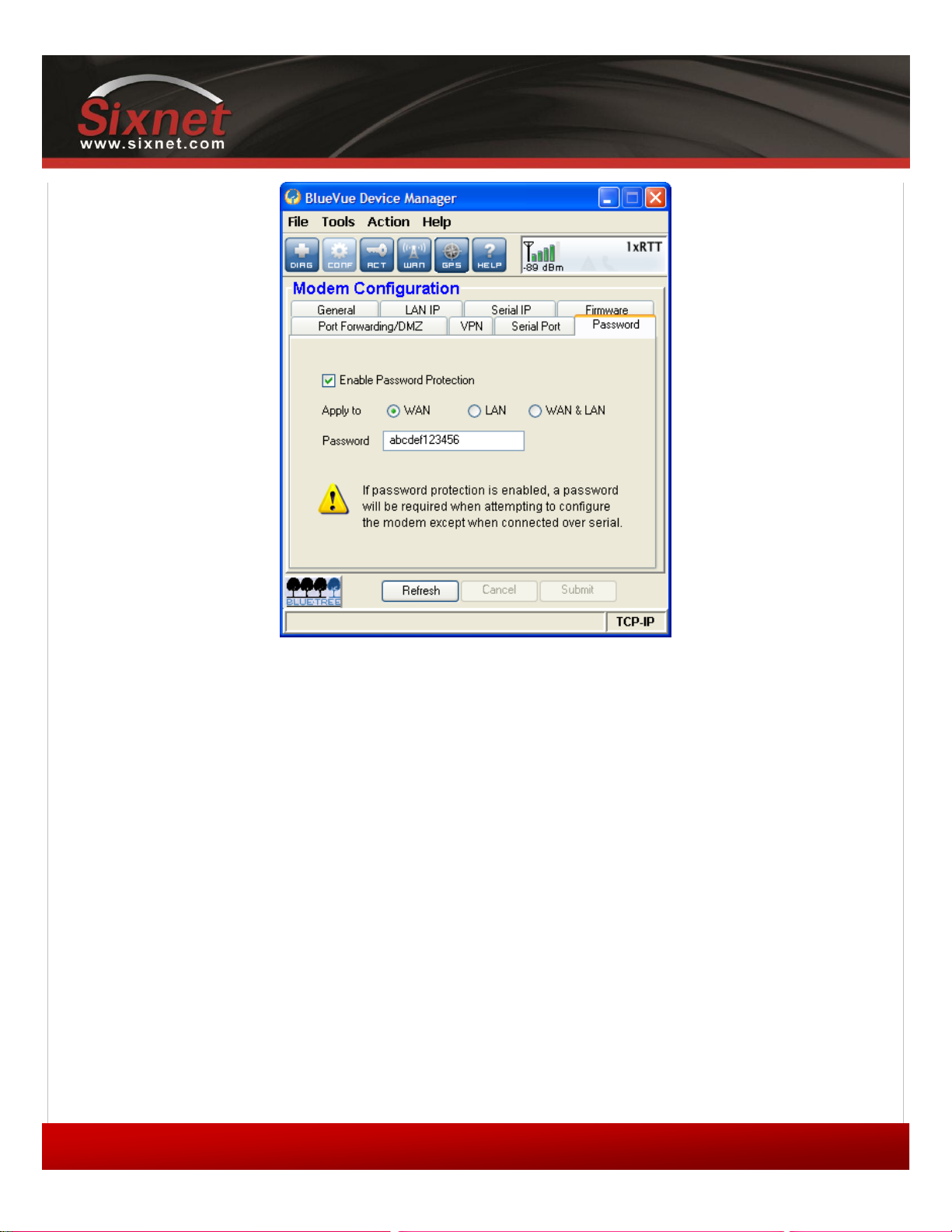
1) Navigate to CONF (Modem Configuration) > Password and check the “Enable” box.
2) Select the interfaces to prompt for a password on. The WAN interface (remote
connections) is the most commonly password-protected interface, however some users may
wish to password-protect both the WAN & LAN interfaces. Note that the modem cannot
prevent configuration changes made from its serial port.
3) Finally, set the modem password. The password must be a case-sensitive string that is 6-
30 characters long.
4) Click Submit to save the changes.
Figure 15 – Enabling password protection
Copyright © 2010 Sixnet LLC. All rights reserved.
Page 40
IndustrialPro™ and MobilityPro™ Gateway
40
1.11 – November 2, 2011
User's Guide
7 Serial IP
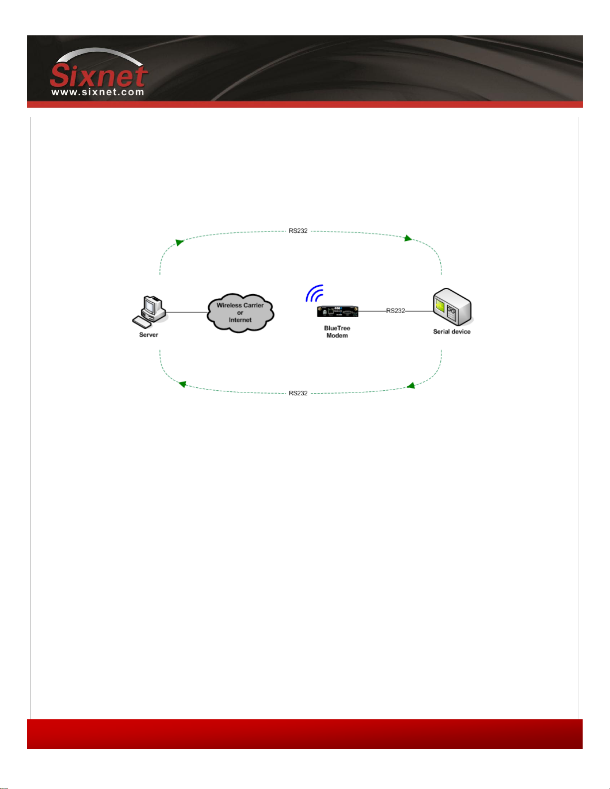
This feature allows communication over the cellular network in two common setups. The first is a server communicating
with a remote serial-only device and the other, a serial-only device communicating with another remote serial-only
device. Serial IP is used to emulate a direct serial connection to the attached device, or to emulate a landline modem.
The modem becomes a transparent middleman routing data back and forth between the poller and the pollee. Serial IP
is most commonly used in telemetry applications such as meter reading and SCADA devices.
Figure 16 – Serial IP
When the modem is in Serial IP mode, IP packets intended for the attached serial device have their IP headers stripped
before being passed on to the device. This means that the serial device receives raw serial data that it can understand.
Inversely, when the serial device is sending data, the modem encapsulates this data in IP packets to be transmitted overthe-air to the remote destination.
When a Serial IP server is running, the modem waits until a connection is made on the defined Serial IP port, then
triggers Serial IP mode. The incoming data will be relayed to the attached serial device. Any output from the serial device
will be sent to the IP of the remote computer that made the connection on the port that the remote computer used to
make the connection.
When using Serial IP, the modem configuration depends on the application requirements. A support note is available.
Copyright © 2010 Sixnet LLC. All rights reserved.
Page 41
IndustrialPro™ and MobilityPro™ Gateway
41
1.11 – November 2, 2011
User's Guide
8 GPS
The BT-5600v2 and BT-5800v2 modems have an embedded GPS receiver which can be used to track their movement.
This feature is commonly used in applications such as asset-tracking and Automatic Vehicle Location (AVL). These
modems support two GPS protocols: the National Marine Electronics Association (NMEA) protocol and the Trimble ASCII
Interface Protocol (TAIP).
The modem can report the fixes acquired from its GPS receiver to:
the local serial port,
up to two servers either local (Ethernet/USB) or remote (over the air) configured for TCP/IP or UDP/IP.
an internal GPS data server (TCP/IP 9999).
the internal event processor where GPS data can be embedded into BEP event messages (raw or structured).
A variety of reporting options are available, ranging from basic NMEA/TAIP timer-based reports to intelligent conditiontriggered reports which leverage the modem's Event Reporting capabilities.
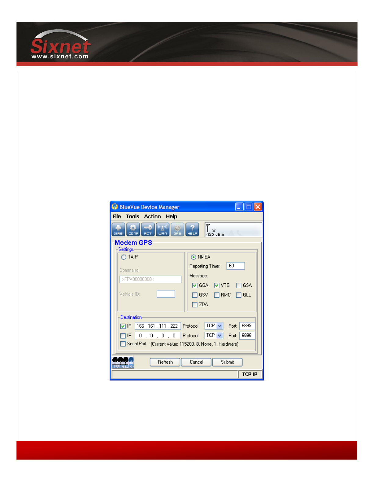
Figure 17 – GPS configuration screen
Copyright © 2010 Sixnet LLC. All rights reserved.
Page 42

IndustrialPro™ and MobilityPro™ Gateway
42
1.11 – November 2, 2011
Message
Contents
Size
GGA
Time, position, and various status information
75 bytes
GLL
Latitude, longitude, and time
48 bytes
GSA
GPS DOP and active satellites
63 bytes
GSV
Active satellites in view
70 bytes
RMC
Time, date, position, course, and speed
67 bytes
VTG
Track made good and ground speed
37 bytes
ZDA
Time and date
35 bytes
User's Guide
8.1 GPS protocols
8.1.1 TAIP
TAIP is configured using a single command string. Read Trimble’s TAIP documentation to learn how to create a
command that meets your needs.
The modem listens on UDP port 21000 for TAIP commands, allowing its configuration to be modified on the fly by
software applications that support TAIP.
8.1.2 NMEA
NMEA uses one or more of the following seven pre-defined, fixed-format messages.
Table 11 – NMEA messages information
Refer to Trimble’s NMEA 0183 documentation for additional information.
8.2 Odometer
The modem can keep track of the total distance traveled by aggregating the data obtained from the GPS fixes. It
calculates the distance traveled based on a straight line between the current and previous fix. By appending these
calculations to a total, the modem is able to keep track of the total distance travelled. When using the NMEA protocol,
the GPS fix is updated every second, so the odometer can be very accurate. However, when using the TAIP protocol, the
GPS fix is acquired as per the configured fix acquisition timer. If the timer is set to a high value such as 5 minutes, then
the odometer will most likely be inaccurate.
8.3 Configuring the modem for GPS reporting
Note
Copyright © 2010 Sixnet LLC. All rights reserved.
Page 43
IndustrialPro™ and MobilityPro™ Gateway
43
1.11 – November 2, 2011
User's Guide
If the modem is configured to report GPS fixes to a remote destination, then the reporting
frequency determines the cellular network bandwidth consumption. A higher reporting frequency
will result in higher bandwidth consumption. Plan carefully to ensure you do not exceed your
monthly bandwidth plan.
The modem can be configured to report GPS in two ways:
The first is to use BlueVue Device Manager for basic GPS reporting. This allows easy configuration of timer-based GPS
reports. Refer to the Basic GPS Reporting in BlueVue Device Manager appendix for a step-by-step configuration
example.
The second is to use AT commands for advanced configuration. This method is more complex and can take advantage of
the modem's Event Reporting capabilities (see next section). Event Reporting allows the modem to report automatically
when a user-defined condition is met. Read the Event Reporting section for details.
Copyright © 2010 Sixnet LLC. All rights reserved.
Page 44

IndustrialPro™ and MobilityPro™ Gateway
44
1.11 – November 2, 2011
User's Guide
9 I/O Management
BlueTree offers a complete set of AT commands to query or set its general purpose and dedicated input and output pins.
This section is only meant to offer a basic outline of how the user can interact with the modem’s I/Os.
The actual modem I/O depends on the model. Please refer to 1Product Overview for details.
The modem’s Event Reporting feature (explained in the Event Reporting section) covers I/Os as well. This can allow the
automation of queries and set the modem to report to a local or remote destination when an input value reaches a
certain threshold, or to take action and trigger a digital output.
9.1 Digital Output control
The modem’s digital output(s) can be used to toggle peripheral equipment ON or OFF. Peripherals such as lights, sirens,
valves, door lock mechanisms, and/or ignitions can be controlled through these I/Os.
Example of turning ON digital output 2:
AT+BDOSET=DO2,1
Example of turning OFF digital output 1:
AT+BDOSET=DO1,0
9.2 Digital Input state query
The modem monitors its general purpose digital input(s) as well as ignition for a change in state, along with the
dedicated ignition input. The state of these inputs can be queried by sending the following AT command:
AT+BDIGET?
Sample response from modem (the actual output depends on the modem model):
+BDIGET: DI1,0
+BDIGET: DI2,1
+BDIGET: DI3,0
+BDIGET: DI4,0
+BDIGET: IGN,1
Copyright © 2010 Sixnet LLC. All rights reserved.
Page 45

IndustrialPro™ and MobilityPro™ Gateway
45
1.11 – November 2, 2011
User's Guide
9.3 Analog Input value query
The modem has a 10-bit Analog to Digital Converter (ADC) which allows it to monitor all of its general purpose analog
input(s) for a change in state, along with the dedicated power input. The value of these inputs can be queried by sending
the following command:
AT+BAIGET?
Sample response from modem (the actual output depends on the modem model):
+BAIGET: PWR,13.553
+BAIGET: AI1,3.056
+BAIGET: AI2,1.987
+BAIGET: AI3,0.000
Copyright © 2010 Sixnet LLC. All rights reserved.
Page 46

IndustrialPro™ and MobilityPro™ Gateway
46
1.11 – November 2, 2011
User's Guide
10 Event Reporting
Event Reporting is covered in its own document, the I/O Management & Event Reporting Guide. This section is meant to
provide a general overview of what can be accomplished with the modem’s BlueTree Event Protocol engine.
Event Reporting is used to program the modem to automatically perform an action (such as sending a report) whenever
a user-defined event occurs. An event occurs, or is triggered, when the conditions that define it have been met.
Event Reporting has the same “Store and forward” feature used by the GPS reporting engine, as described in the GPS
section. This ensures that no reports are lost if the modem loses its connection to the cellular network: everything is
saved to memory and forwarded when the connection is reestablished.
10.1 Events
The event that triggers an action can be any of the following:
A timer has finished counting down
An analog input signal has reached a certain value
A digital input signal has changed state
WAN status
The BT-5600v2 and BT-5800v2 modems are equipped with a GPS receiver and can react upon these additional GPSbased event triggers:
The modem is in motion at a particular speed
The modem is in motion in a particular direction (heading)
The modem is unable to acquire a GPS fix
The modem has traveled for a set distance
The ignition (IGN) signal state
Events can also be combined using logical statements to create more complex events. For example, a combination of the
timer and speed event triggers could define an event that would trigger when a vehicle has been speeding, by defining
speeding as moving at 60+ mph for more than 10 seconds. This provides a great amount of control and allows defining
events that meet most if not all potential requirements.
10.2 Store and forward
The modems have a 512 Kbytes memory area dedicated to storing BlueTree Event Protocol reports. It can store
approximately 5000 events (exact amount depends on the configuration). The event is either composed of raw GPS data
(BT-5600v2 and BT-5800v2 only) or structured in a BEP message payload.
Copyright © 2010 Sixnet LLC. All rights reserved.
Page 47

IndustrialPro™ and MobilityPro™ Gateway
47
1.11 – November 2, 2011
User's Guide
This feature will activate automatically when the modem cannot reach its reporting destination. The report destination
has to be configured with TCP/IP (with or without BEP ACK) or with UDP/IP (with BEP ACK only). Events are not stored
when the reporting destination is UDP/IP without BEP ACK. The modem will save the reports in its memory buffer until it
is able to send them or when they are acknowledged ensuring that no event has been lost.
When Store And Forward is activated, the modem stores Event data in memory on a First In First Out (FIFO) basis. This
means that if the modem is unable to transmit fixes over an extended period of time, and the memory becomes full as a
result, the newest events overwrite the oldest stored events. When the connection to the report destination is reestablished, the modem will send all the stored fixes to the destination.
Stored events are transferred to non-volatile memory when the IGN input signal is low (BT-5600v2 and BT-5800v2) or
when the modem is shutdown via an AT command. Stored events are not lost if the modem is shutdown through
ignition delay timer.
10.3 Actions
The modem can perform one or more of the following actions when an event is triggered:
Change the state of one of its digital outputs
Turn its radio-frequency module ON or OFF
10.4 Reports
When an event is triggered, the modem can send a report to up to 10 local or remote destinations.
All reports are custom-formatted by the BlueTree Event Protocol as defined in the I/O Management & Event Reporting
document, so they require some manipulation on the destination end in order to be parsed properly.
A report can contain one or more of the following information:
The modem's name and ESN
The modem's RSSI (signal strength)
The value of the analog and digital inputs
The modem's odometer value (total distance traveled)
A GPS report containing NMEA or TAIP data
10.4.1 ACK
The modem can be configured to wait for confirmation (“ACK”) from the remote server that it has received the report. If
this confirmation does not come, the modem will assume the report has not been received and will continue sending
the same report at a configured interval until it receives confirmation of receipt.
Copyright © 2010 Sixnet LLC. All rights reserved.
Page 48

IndustrialPro™ and MobilityPro™ Gateway
48
1.11 – November 2, 2011
User's Guide
10.4.2 Sync flags
To ease the parsing of the packets on the server, the modem can set a sync flag in the beginning and end of each packet
it sends.
Copyright © 2010 Sixnet LLC. All rights reserved.
Page 49

IndustrialPro™ and MobilityPro™ Gateway
49
1.11 – November 2, 2011
Cable type
Loss per 100 feet
8216 (RG58)
31 dB
8267 (RG213)
7.6 dB
LMR-400
3.9 dB
LMR-500
3.15 dB
LMR-600
2.5 dB
LMR-1200
1.26 dB
11 Hardware Installation
11.1 Mounting the BT-5x00v2 series modem
Horizontally mount the modem using four #6 screws pan or fillister head onto its mounting
feet
11.2 Mounting the BT-6000 series modem
There are 3 different ways to mount a BT-6000 series modem:
Horizontally using two #6 screws pan or fillister head onto its horizontal mounting feet
Vertically using two #6 screws pan or fillister head onto its vertical mounting feet
Vertically using a DIN rail clip
11.3 Cellular antenna
The selected cellular antenna(s) must meet the following specifications:
User's Guide
Maximum rated gain of 3dBi for Cellular band and 4dBi for PCS band
Frequency bands:
CDMA: Dual-band 800 & 1900 MHz
EDGE: 850/1900/900/1800 MHz
HSPA: 850/1900/2100 MHz
Nominal 50 ohm impedance
Voltage Standing Wave Ratio (VSWR) less then 2.5:1
Male SMA connector
The length of the antenna cable may affect the signal strength. Choose the appropriate cable type and length. The table
below provides can help pre-determine the loss to expect.
Table 12 – dB loss per 100 feet of cable type
Copyright © 2010 Sixnet LLC. All rights reserved.
Page 50

IndustrialPro™ and MobilityPro™ Gateway
50
1.11 – November 2, 2011
User's Guide
11.3.1 Installation and verification
When installing the antenna, follow the FCC and Industry Canada guidelines and keep the following in mind:
Mount the antenna(s) at least 30 cm (12 inches) from other antennas
Do not install the antenna in a closed metallic enclosure (such as a cabinet or the trunk of a
car).
Once a modem has a signal, the Signal LED indicator will start flashing according to the signal strength. Additionally,
BlueVue Device Manager will display the received signal strength (RSSI) in the top right. The modem should have at the
very least one bar of signal strength.
11.3.2 Antenna diversity
The BlueTree 5000v2 and 6000 series modems except for the BT-64xx series have two antenna connectors available,
labeled Antenna and Diversity.
Antenna: This is the main antenna that is used for data transmission. It is mandatory to
have the Antenna port connected to an antenna.
Diversity: This is the diversity antenna, used to improve on the signal strength obtained
from the main antenna. This antenna is not mandatory however it will improve throughput
in low signal and fringe areas.
Diversity is a transmission technique that consists of using two separate antennas to achieve the most robust cellular
signal possible. Diversity will help achieve fast, reliable data throughput in applications that require a high amount of
bandwidth.
To get the best performance, the Diversity antenna should be placed at a minimum of 5/8 of a wave length away from
the other antenna. Therefore, the minimum spacing for antennas in the 800 MHz frequency is 5/8 * 13.5” = 8.5”. The
diversity antenna can be spaced further away than this, ideally in increments of 13.5”: 22”, 35”, etc. For a 1900 MHz
only network, the optimal distance would be 5/8 * 6.2” = 4”.
Copyright © 2010 Sixnet LLC. All rights reserved.
Page 51
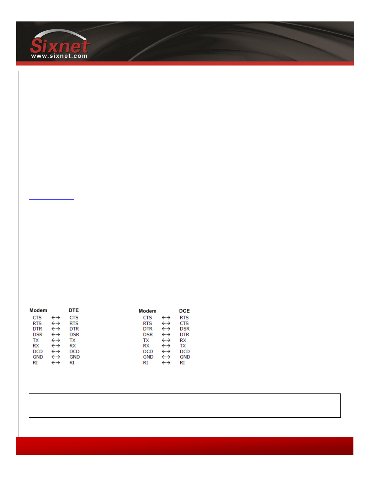
IndustrialPro™ and MobilityPro™ Gateway
51
1.11 – November 2, 2011
User's Guide
11.4 Ethernet cable
If you are connecting to the modem via the Ethernet port, you will need a straight or crossover category 5 cable with
two 8-pin RJ45 connectors on each end.
To visually confirm that Ethernet cabling was done properly, check the LED indication on the Ethernet port located at the
rear panel of the modem. The Link LED should be on when the right cable is used.
11.5 USB cable
This is an Ethernet-over-USB connection which behaves like an Ethernet connection. It can only be connected to a PC
with Windows XP or Windows Vista installed. If you are connecting to the modem via the USB port, you will need a Type
A plug to Type B plug USB cable for the BT-5x00v2 series modems and a mini Type B plug to Type A plug for the BT-6000
series modems. In order for the USB connection to work, you need to install the BlueTree USB driver which is available
at www.sixnet.com. The driver is automatically installed during BlueVue Device Manager setup.
11.6 Serial cable
The modem has all its serial port pins enabled. If all the pins are enabled on the attached serial device, it is important to
know whether the device is using DTE or DCE as a communication mode.
The modem is a DCE device, so use a straight-through serial cable between the modem and a DTE device such as a
terminal. Use a NULL modem cable adapter between the modem and a DCE device such as another modem.
If using custom wiring or if some pins are disabled, follow the guidelines below. The wiring will vary depending on
whether the attached serial device is a DTE or DCE.
11.7 Power source
IMPORTANT
Any installations involving electrical wiring and connections should be done by someone who is
experienced in this field.
Copyright © 2010 Sixnet LLC. All rights reserved.
Page 52
IndustrialPro™ and MobilityPro™ Gateway
52
1.11 – November 2, 2011
User's Guide
As described in the Power specifications and consumption section, the modem can be powered using:
4-pin Molex connector for the BT-5x00v2 and BT-6x00 models
4-pin screw terminal for the BT-6x01, BT-6x01EB and BT-6x21 models
DC 2.5mm round plug for all models except the BT-5x00v2 series
PoE (Power over Ethernet) for BT-6x01EB models
WARNING
DC 2.5mm Barrel Adapter shall not be used in hazardous locations.
11.7.1 Powering up the modem
The modem will power up as soon as an 8 to 30 VDC voltage is applied to one of its power inputs and shuts off when this
input voltage is below 4 VDC.
In addition, BT-5x00v2 modems require the IGN signal to be ON for the modem to start. When BT-5x00v2 modems
detect the IGN signal transition to OFF, it engages its shutdown after a programmable delay.
11.7.2 Testing the power connection
Check the PWR light on the modem: if it is turned on then the modem is powered. If it’s off, then review the installation
procedures.
If LED indicators are not accessible to the installer, a computer can be used to verify its functionality by running BlueVue
Device Manager and attempting to connect to the modem.
Copyright © 2010 Sixnet LLC. All rights reserved.
Page 53
IndustrialPro™ and MobilityPro™ Gateway
53
1.11 – November 2, 2011
User's Guide
12 Appendixes
12.1 BlueVue Device Manager Troubleshooting
Before troubleshooting, download and install the latest version of BlueVue Device Manager from
http://www.sixnet.com/ .
12.1.1 (ETHERNET) The BlueVue Device Manager message box displays “Detecting Modem at
192.168.0.1” indefinitely
Connect the modem to a computer using an Ethernet cable, and open BlueVue Device Manager. Set BlueVue Device
Manager’s connection type to IP. BlueVue Device Manager will attempt to connect to 192.168.0.1 by default.
Possible cause #1
The cable is damaged.
Troubleshooting
Check the Link LED on the modem’s Ethernet connector (located on the back of the modem). If the LED is off, verify the
cable.
Possible cause #2
The computer’s local IP configuration is incorrect.
Troubleshooting
1) In Windows XP, go to Control Panel > Network Connections and select the local area
connection that corresponds to the Ethernet port in the “LAN or High-Speed Internet” list
(it’s usually “Local Area Connection 1”).
2) Right-click the connection and click Properties. Select Internet Protocol (TCP/IP) in the
list and click Properties.
3) Write down the existing values in order to restore them after configuring the modem, then
select Obtain an IP address automatically and Obtain DNS server address
automatically. The computer will now be ready to use the modem to access the Internet.
Possible cause #3
The modem is in a different network and DHCP is disabled. (This issue does not apply to brand-new modems at factory
settings. It only applies to modems that have had their configuration modified.)
Copyright © 2010 Sixnet LLC. All rights reserved.
Page 54

54
1.11 – November 2, 2011
Troubleshooting
Follow the instructions below:
1) Connect the computer to the modem using a straight serial cable
2) Set BlueVue Device Manager to connect to the modem over the serial port by changing
the connection type to Serial
3) Once the modem has been accessed, navigate to CONF (Modem Configuration) > LAN
IP
4) Under Ethernet, set the Modem IP to 192.168.0.1
5) Confirm that DHCP is enabled and that the DHCP Start IP is 192.168.0.4. Set the End
IP range to any value higher than 192.168.0.4. The default is 192.168.0.39.
6) Click Submit to save the changes
7) Reset the modem and restart the computer
IndustrialPro™ and MobilityPro™ Gateway
User's Guide
12.1.2 (USB) The BlueVue Device Manager message box displays “Detecting Modem at
192.168.111.1” indefinitely
Possible cause #1
The USB driver is not installed.
Troubleshooting
The USB driver for Windows must be installed before the modem’s USB functionality can be used. Visit
http://www.sixnet.com/ to download the USB driver then install it. It may be necessary to reboot the computer.
Possible cause #2
The modem has an old firmware version which does not support USB.
Troubleshooting
The USB functionality was introduced in version 3.0 of the firmware. Upgrade the modem’s firmware to the latest
version available at http://www.sixnet.com/. A walkthrough can be found in the Firmware Upgrades appendix.
Copyright © 2010 Sixnet LLC. All rights reserved.
Page 55

IndustrialPro™ and MobilityPro™ Gateway
55
1.11 – November 2, 2011
User's Guide
12.1.3 (SERIAL) The BlueVue Device Manager message box displays “COMx is already in use”
Possible cause
Another software application is already using the COM port.
Troubleshooting
Close all applications that could be using the serial port, including other instances of BlueVue Device Manager, then try
again.
12.1.4 (SERIAL) The BlueVue Device Manager message box displays “Detecting modem on
COMx” indefinitely, or displays a warning about an unsupported modem
Examine the DTR LED. If it is off, then the computer and the modem are not communicating.
Possible cause
The wrong type of cable is being used.
Troubleshooting
Use a straight-through RS232 standard DB9 cable. If using a custom-made cable, confirm that it follows the instructions
in Section 11.6. If the correct cable is being used, then the DTR LED on the modem will turn on when BlueVue Device
Manager attempts to access it.
Possible cause
BlueVue Device Manager is trying to connect to the wrong COM port.
Troubleshooting
Confirm that the correct COM port is selected in BlueVue Device Manager. It will attempt to use COM1 by default, but
computers with built-in dial-up modems might have COM1 assigned to the built-in modem instead. To set the COM port
BlueVue Device Manager should use, click on Tools > Settings > Connection and browse through the available COM
ports. If the DTR LED turns on, then you will have found the right COM port.
Copyright © 2010 Sixnet LLC. All rights reserved.
Page 56

IndustrialPro™ and MobilityPro™ Gateway
56
1.11 – November 2, 2011
User's Guide
12.1.5 (SERIAL) The BlueVue Device Manager message box displays “Detecting modem on
COMx” and then “Modem is not responding”
Possible cause
BlueVue Device Manager and the modem are using different serial port settings.
Troubleshooting
Installing BlueVue Device Manager 1.7.1 or later will allow communication with a modem regardless of its serial settings.
12.1.6 The BlueVue message box displays “[Modem]…is not responding to expected commands.
Contact BlueTree Support.”
Possible cause
BlueVue Device Manager has detected a potential hardware issue.
Troubleshooting
Contact BlueTree support at [email protected].
Copyright © 2010 Sixnet LLC. All rights reserved.
Page 57
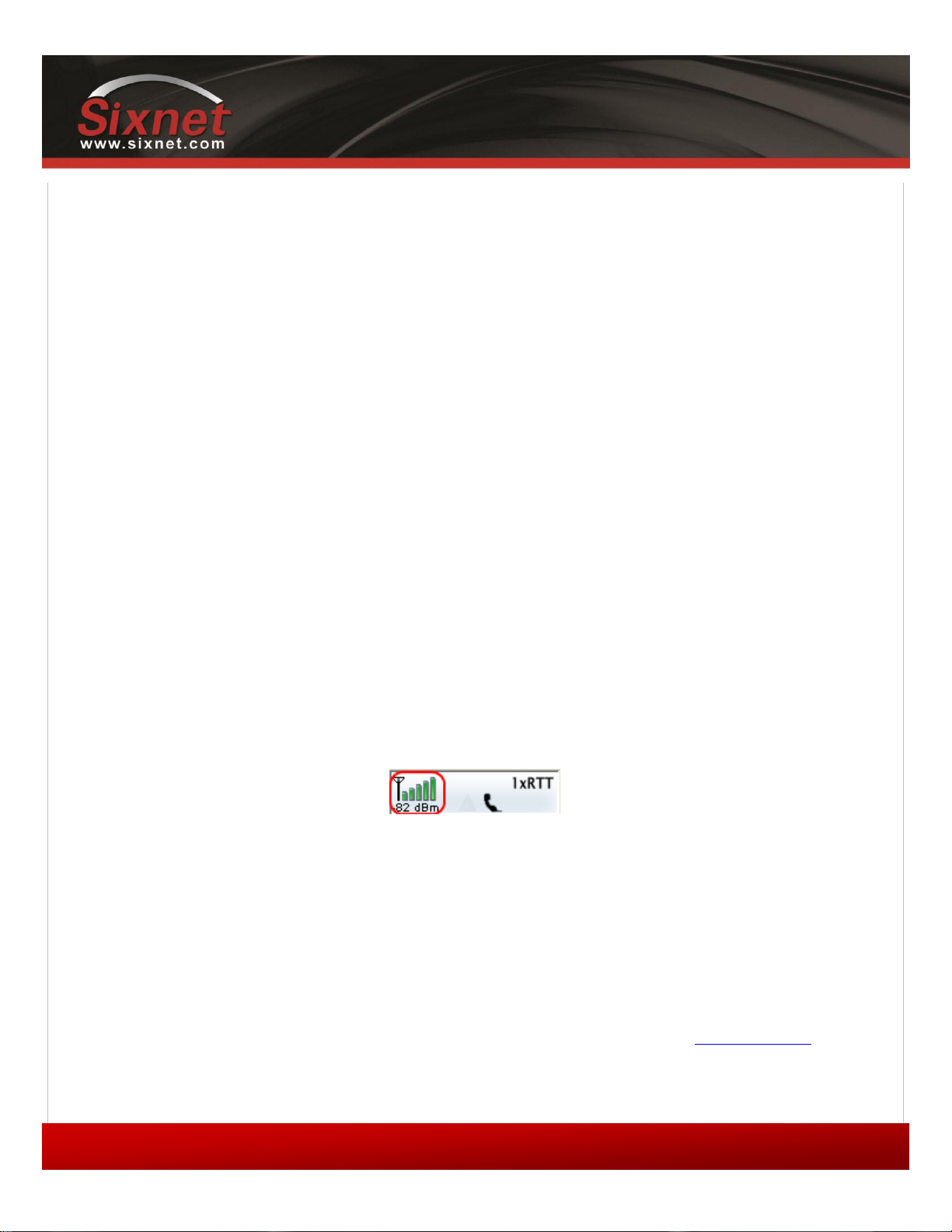
IndustrialPro™ and MobilityPro™ Gateway
57
1.11 – November 2, 2011
User's Guide
12.2 Activation Troubleshooting
When the modem is connected to the cellular network, its WAN LED will stay on and will flash to indicate activity,
BlueVue Device Manager’s Modem Diagnostic screen will display a WAN IP. If the modem is not connected, the WAN
light will be off, and the displayed WAN IP will be “N/A”. This appendix covers issues with connecting to the network. If
your modem is connected to the network but you cannot browse the internet, refer to 12.3 Troubleshooting.
Each of the following conditions must be met before a modem can connect to the cellular network:
1) The modem must be within coverage, and have an acceptable RF signal strength
2) The modem must be activated for use on the cellular network (CDMA) or have a valid SIM
card (EDGE and HSPA)
3) The modem must be configured to connect to the cellular network
4) If the cellular carrier requires a user name and password, the modem’s connection
parameters (WAN Settings) must be configured
12.2.1 Verifying the signal strength
The modem’s SIGNAL LED should always be flashing or solid ON when it has a strong enough signal to detect a cellular
network. Additionally, the signal strength is displayed in the information box in the top right of the BlueVue Device
Manager window. The minimum required for communication is 1 signal strength bar; however, a signal this weak is not
likely to provide a stable connection.
If the SIGNAL LED stays OFF, or if the signal strength is lower than -98 dBm (such as -105 dBm), there may be an issue
with the antenna or the modem may be in a low coverage area.
Figure 18 – Modem with good signal strength
12.2.2 Confirming the success of activation (CDMA only)
Once a modem has been activated, BlueVue Device Manager will display its phone number in the WAN (Modem WAN
Settings) screen (some GSM carriers chooses to have the modem phone number hidden. In this case, the phone # may
appear as blank).
For CDMA modems, if the phone number is blank, or does not correspond to the account’s phone number, then
activation has not been performed. Follow the instructions written in the Quick Start Guide that shipped with the
modem to perform activation. The latest Quick Start Guide is also available for download at www.sixnet.com
Copyright © 2010 Sixnet LLC. All rights reserved.
Page 58
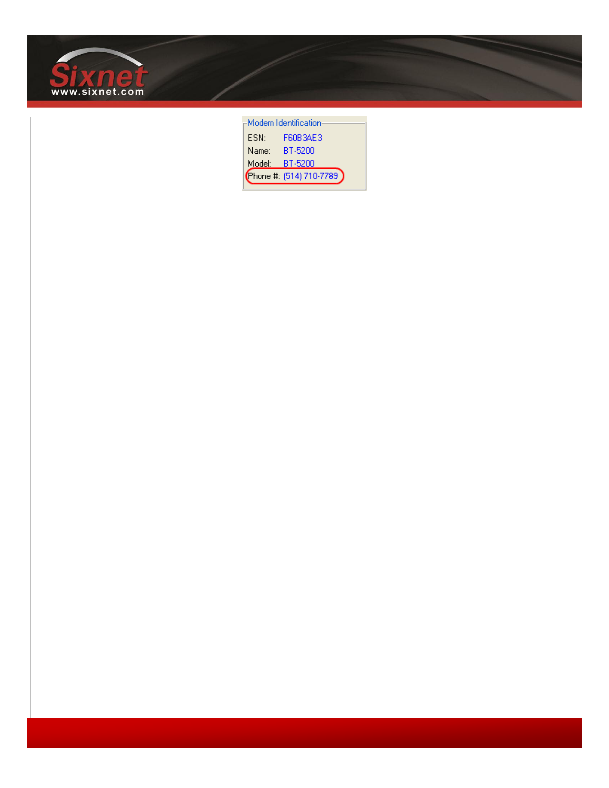
IndustrialPro™ and MobilityPro™ Gateway
58
1.11 – November 2, 2011
User's Guide
Figure 19 – Phone number being displayed on the Modem Diagnostic screen after
activation
12.2.3 Configuring the Connection Initiation
The modem must be configured to connect to the network.
To do this, open BlueVue Device Manager and navigate to WAN (WAN Settings), and then ensure that the following
settings are applied:
1) The Dial String is #777 for CDMA networks and *99***1# or *99# for GSM networks
2) The Connection Initiation is Always On (default setting for firmware 3.60 and later)
Click Submit to apply any changes. The modem should now connect to the cellular network. Refer to this section’s
introduction for instructions on how to verify whether your modem is connected to the network or not.
12.2.4 Configuring the User Profile
If the modem’s Signal LED turns on for a few seconds then turns off, this indicates that authentication on the cellular
network is failing. The modem’s User Profile will need to be configured.
Navigate to WAN (WAN Settings). Enter the user name and password as provided by the cellular service provider.
12.2.5 Conclusion
As mentioned previously, when the modem is connected to the cellular network, BlueVue Device Manager’s Modem
Diagnostic screen will display a valid WAN IP and the WAN LED will remain on and flashing to indicate activity of the
cellular interface.
Copyright © 2010 Sixnet LLC. All rights reserved.
Page 59
IndustrialPro™ and MobilityPro™ Gateway
59
1.11 – November 2, 2011
User's Guide
Figure 20 – WAN IP being displayed after the modem successfully connects to the
cellular network
If after going through all of the above troubleshooting steps, the modem still does not acquire a WAN IP, then it is very
likely that the account is not enabled by the cellular carrier. Contact the cellular service provider and ask them:
- CDMA: to confirm that the phone number assigned matches the modem’s ESN (electronic serial number) as
shown in DIAG (Modem Diagnostic), and that the account is ready to be used.
- GSM (EDGE/HSPA): to confirm that the SIM card holds a valid account (the SIM card number will be
required).
Copyright © 2010 Sixnet LLC. All rights reserved.
Page 60

IndustrialPro™ and MobilityPro™ Gateway
60
1.11 – November 2, 2011
User's Guide
12.3 Troubleshooting
This appendix assumes that the modem is currently online, and therefore the problem cannot be attributed to a lack of
connectivity. BlueVue Device Manager’s Modem Diagnostic screen should be displaying a valid WAN IP, i.e. an IP other
than “N/A”. If this is not the case, refer to 12.2Activation Troubleshooting.
12.3.1 You cannot browse the Internet
Possible cause #1 (Ethernet only)
The computer’s local IP configuration is incorrect.
Troubleshooting
The computer must be in the same subnet as the modem and must have the modem set as its gateway. The easiest way
to achieve this is to enable automatic IP configuration (DHCP) on the computer.
1) In Windows XP, go to Control Panel > Network Connections (for Windows Vista, go to
Control Panel > Network and Sharing Center) and select the local area connection that
corresponds to the Ethernet port in the “LAN or High-Speed Internet” list (it’s usually
“Local Area Connection”).
2) Right-click the connection and click Properties. Select Internet Protocol (TCP/IP) in
the list and click Properties.
3) Write down the existing values in order to restore them if needed, then select Obtain
an IP address automatically and Obtain DNS server address automatically. Click OK
to close both dialog boxes, and reset the computer. It should now be ready to use the
modem to access the Internet.
Possible cause #2 (Serial only)
You’re connected to the modem using a serial cable and did not start a Dial-Up Networking session.
Troubleshooting
Unlike Ethernet/USB, you must configure Windows to use a serial cable to access the network. Even though the modem
is connected to the Internet, your computer is not configured to browse the Internet through the modem.
You will need to install a standard 33600bps modem driver and create a Dial-Up Networking session in order to be able
to browse the internet. Refer to the Dial-Up Networking in Windows appendix for a walkthrough for creating a Dial-Up
Networking connection in Windows XP.
Possible cause #3
Your web browser is configured to use a proxy which cannot be accessed by the modem.
Copyright © 2010 Sixnet LLC. All rights reserved.
Page 61

IndustrialPro™ and MobilityPro™ Gateway
61
1.11 – November 2, 2011
User's Guide
Troubleshooting
1) Open a command prompt window by clicking Start > Run then entering “cmd” in the
Run window.
2) At the command prompt, type ping google.com and press Enter.
If you get a “Reply from xxx.xxx.xxx.xxx: bytes=32 time=xxxms TTL=xxx” response, then your web browser is configured
to use a web proxy which is preventing you from browsing the Internet through the modem. Consult your network
administrator for help on fixing this issue.
Possible cause #4
The cellular account does not allow web access.
Troubleshooting
Certain cellular accounts, particularly those where security is a high concern, do not allow web access. If you are
attempting to test the connection by browsing the Internet, you may not be able to do so because of this account
restriction.
12.3.2 (TCP/IP) You cannot communicate with a computer/device behind the modem
This section is meant for TCP/IP connectivity. If the device is a serial-only device, skip to the next issue.
Possible cause #1
Your cellular carrier is operating a firewall which is blocking your attempts to connect.
Troubleshooting
Certain carriers have a firewall turned on by default that blocks all incoming connections.
3) Open a command prompt window by clicking Start > Run then typing “command” in the
Run window
4) Type telnet xxx.xxx.xxx.xxx 6070 where x is the modem’s WAN IP as assigned by the
carrier
If you do not connect and see a “Welcome to BlueTree Wireless” message, then your carrier is likely blocking incoming
connections. Contact your cellular service provider and ask them to open the TCP and UDP ports you will be using to
access the device.
Copyright © 2010 Sixnet LLC. All rights reserved.
Page 62

IndustrialPro™ and MobilityPro™ Gateway
62
1.11 – November 2, 2011
User's Guide
Possible cause #2
Your computer (from which you are initiating the connection) or network has a firewall blocking outgoing connections.
Troubleshooting
Confirm with your IT technician that no firewall is blocking outgoing connections.
Possible cause #3
You did not perform the appropriate port-forwarding rules on the modem.
Troubleshooting
The modem must be configured to forward incoming traffic to the device, otherwise your connection attempts will
never reach the device. Refer to IP Networking Features for further details.
12.3.3 (SERIAL) You cannot communicate with a device behind the modem
First, make sure the modem is configured to enable outside communication with the attached device. Refer to the
“Serial IP” section of the main guide for details. The troubleshooting steps below assume the modem is configured
properly.
Possible cause #1
The modem and the device are using different serial port settings.
Troubleshooting
Using BlueVue Device Manager, navigate to CONF (Modem Configuration) > Serial Port, and change the serial port
settings to the same values as those of the serial device. If the CTS and RTS pins are partially (or both) disabled, set the
modem to use no flow control (“none”).
Possible cause #2
The cable wiring is incorrect.
Troubleshooting
Refer to Section 11.6 for details on the required cable type.
Copyright © 2010 Sixnet LLC. All rights reserved.
Page 63

IndustrialPro™ and MobilityPro™ Gateway
63
1.11 – November 2, 2011
User's Guide
Possible cause #3
The DTR signal is inconsistent.
Troubleshooting
A flickering DTR signal will interrupt communication with the modem. The modem can be configured to ignore the
changes in the DTR state. In BlueVue Device Manager, navigate to CONF (Modem Configuration) > Serial Port, and
check the option to Ignore DTR.
Copyright © 2010 Sixnet LLC. All rights reserved.
Page 64

IndustrialPro™ and MobilityPro™ Gateway
64
1.11 – November 2, 2011
User's Guide
12.4 Firmware Upgrades
BlueTree periodically releases updates to the BlueX firmware used on the BT-5x00v2 and BT-6000 series modems. These
updates improve the modem's stability and functionality by addressing issues and introducing new features. It is
recommended to always upgrade to the latest version of the firmware.
Firmware upgrades can only be performed if BlueVue Device Manager is accessing the modem through an IP connection
such as a local Ethernet, USB connection or a remote connection over the Internet. It is not possible to update the
firmware using a serial cable.
Up until firmware 3.6.1, the modem’s WAN IP address had to be static to perform a successful upgrade. If the WAN IP
address was dynamic, (i.e. if its IP changes regularly), and the IP is changed when the modem resets during the firmware
update procedure, then BVDM will not be able to reconnect and finalize the update, and the modem will revert back to
its previous firmware the next time it is reset or power recycled. Firmware 3.6.1 has changed this and allows both static
and dynamic WAN IP addressing schemes to update remotely with success.
12.4.1 Downloading the latest firmware
Download the latest standard firmware package files from www.sixnet.com, and extract the zip file to a folder on your
hard drive. It contains a file named abt_version_bt6k.upd as well as the release notes document. .
Copyright © 2010 Sixnet LLC. All rights reserved.
Page 65
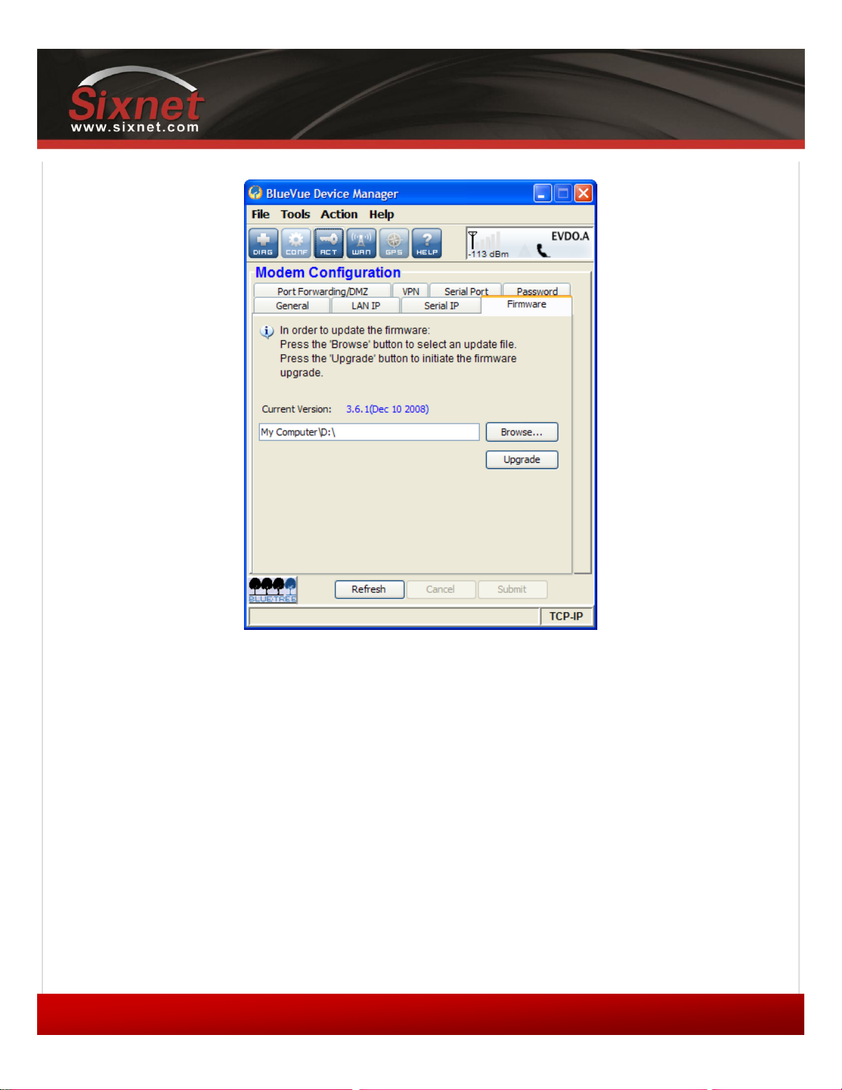
IndustrialPro™ and MobilityPro™ Gateway
65
1.11 – November 2, 2011
Performing the ABT firmware upgrade
User's Guide
Figure 21 – Upgrading the firmware
1) Navigate to CONF (Modem Configuration) > Firmware.
2) Click the magnifying Browse… button and locate the abt_version_bt6k.upd file from
the package that you extracted during the first step.
3) Click Upgrade.
4) Wait for BlueVue Device Manager to confirm that the firmware update was completed. If the
upgrade is being performed locally, it should approximately take 2 minutes. If it the
upgrade is being performed remotely, then it could take up to 5 minutes depending on
download speed.
Copyright © 2010 Sixnet LLC. All rights reserved.
Page 66
IndustrialPro™ and MobilityPro™ Gateway
66
1.11 – November 2, 2011
User's Guide
12.5 Sending AT Commands
AT commands are short text strings that can be sent to the modem to set, remove and query modem's configuration
parameters. BlueVue Device Manager is a software application that provides a graphical user interface designed to avoid
manual entry of AT commands. However, not all configuration commands are available in BlueVue. Additionally, BVDM
is only available in Microsoft Windows operating systems. For these and various other reasons, some users may want to
send AT commands to the modem.
The full list of AT commands and their description is in the AT Command Reference manual, available at
www.sixnet.com.
IMPORTANT:
After sending AT commands to configure the modem, you must send AT&W to save the changes.
Otherwise, they will be lost the next time the modem resets. You do not need to send AT&W after
each command: you can send it just once after you’re done configuring the modem.
Note:
AT commands must end with a Carriage Return character. If you are not using a Windows
operating system, you may have to configure your terminal emulator software or telnet client
software to end lines with a Carriage Return (0x0D or \r).
12.5.1 Sending AT commands over an IP connection
If you can reach the modem using a crossover Ethernet cable, or a USB cable, or remotely to the modem's WAN IP, AT
commands can be sent by performing a TCP (telnet) connection to the modem on port 6070. Here is an easy way to do
this in Windows:
1) Click the Start button, then Run.
2) In the Run window, type command and click OK. A command prompt window will open.
3) Type telnet xxx.xxx.xxx.xxx 6070 (replacing the x’s with the modem’s IP) and press
Enter. By default, the modem's IP will be 192.168.0.1 for Ethernet, and 192.168.111.1 for
USB. If connecting to a remote modem, you will need to know its WAN IP.
4) If the modem is password protected, you will have to enter its password.
5) You should get a "Welcome to BlueTree Wireless" message. You can now send AT
commands.
12.5.2 Sending AT commands over a serial connection
If connected to the modem using a straight DB9 serial cable, AT commands can be sent using a terminal emulation
software. The terminal and the modem must be using identical serial port settings to communicate. By default, the
modem uses 115200 bps, 8 data bits, no parity, 1 stop bit, and hardware flow control. Below is an example for
connecting to a modem with default serial port settings.
Copyright © 2010 Sixnet LLC. All rights reserved.
Page 67

IndustrialPro™ and MobilityPro™ Gateway
67
1.11 – November 2, 2011
User's Guide
1) Open HyperTerminal. To do so, click the Start button and then click on Run. In the Run
window, enter hypertrm and click OK.
2) On the Connection Description screen, enter any name, select any icon, and then click
OK.
3) On the Connect To screen, change the Connect using value to the COM port the modem
is connected to and click OK.
4) On the COM Properties screen, change the Bits per second value to 115200. Leave all
the other options untouched (8, None, 1, Hardware), and click OK.
You should now be able to send AT commands. You will not see what you type until you send the command ATE1 or
enable echo in HyperTerminal's settings, but the commands will still be sent to the modem. Send ATI1 and confirm that
you see the words “BlueTree Wireless” in the response.
Copyright © 2010 Sixnet LLC. All rights reserved.
Page 68
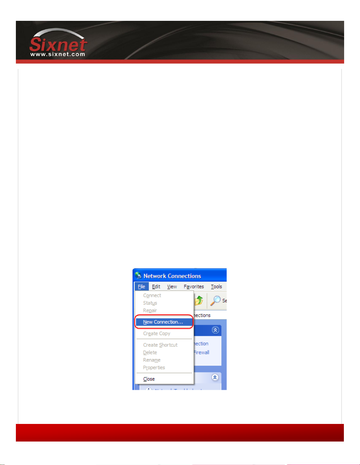
IndustrialPro™ and MobilityPro™ Gateway
68
1.11 – November 2, 2011
User's Guide
12.6 Dial-Up Networking in Windows
This appendix shows how to create a dial-up networking session to access the Internet/cellular network when connected
to the modem using a serial cable. Although these instructions are written for computers running Microsoft Windows
XP, this procedure should be similar with other versions of Microsoft Windows.
12.6.1 Installing the modem driver
1) Click Start > Run, type control modem.cpl and then click OK to open the Phone and
Modem Options panel
2) Click the Modems tab and then click Add
3) You may be required to enter location information if this is the first modem installed. If this
is the case, choose your region and area code in the information window.
4) Check the box labeled Don’t detect my modem… and then click Next
5) Select Standard 33600 bps Modem from the list and click Next
6) Select the COM port that the modem is attached to then click Next
7) Click Finish to complete the driver installation
12.6.2 Creating a Dial-Up Networking session
Figure 22 – Creating a new connection in Windows XP
Copyright © 2010 Sixnet LLC. All rights reserved.
Page 69

IndustrialPro™ and MobilityPro™ Gateway
69
1.11 – November 2, 2011
User's Guide
1) Click Start > Run, type control ncpa.cpl and then click OK to open the Network
Connections panel.
2) Click on File > New Connection (as per the screenshot above)
3) The New Connection Wizard welcome dialogue will appear. Click Next.
4) The Network Connection Type dialogue will appear. Select Connect to the Internet and
click Next.
5) The Getting Ready dialogue will appear. Select Set up my connection manually and click
Next. Name the connection in the new window.
6) The Internet Connection dialogue will appear. Select Connect to a dialup modem and
click Next.
7) If there is more than one modem installed in Windows, the Select a Device dialogue
will appear. If this is the case, select Standard 33600bps Modem and click Next.
Otherwise, proceed to the next step.
8) The Connection Name dialogue will appear. Type in any name for the connection and click
Next.
9) The Phone Number To Dial dialog will appear. Enter #777 for CDMA or *99***#1 or *99#
for GSM (EDGE/HSPA).
10) The Internet Account Information box will appear. Enter the username and password
associated with the account (if any) in the corresponding fields and click Next.
The DUN connection is now set up, and your PC is ready to connect to the cellular network. Right-click your new
connection in the Network Connections list, and click Connect.
Once the connection has been established, the modem will by default assign the attached device the LAN IP 192.168.0.3,
while the modem itself will have the LAN IP 192.168.0.2. These settings are configurable in BlueVue Device Manager
under CONF (Modem Configuration) > LAN IP > PPP.
Copyright © 2010 Sixnet LLC. All rights reserved.
Page 70

IndustrialPro™ and MobilityPro™ Gateway
70
1.11 – November 2, 2011
User's Guide
12.7 Warranty
Sixnet warrants its cellular modems against all defects in materials and workmanship for a period of three (3) years from
the date of purchase. The sole responsibility of Sixnet under this warranty is limited to either repair or, at the option of
Sixnet, replacement of the cellular modem. There are no expressed or implied warranties, including those of fitness for a
particular purpose or merchantability, which extend beyond the face hereof. Sixnet is not liable for any incidental or
consequential damages arising from the use, misuse, or installation of the Sixnet modem. This warranty does not apply if
the serial number label has been removed, or if the cellular modem has been subjected to physical abuse, improper
installation, or modification. The unit is automatically registered for warranty at the date it is purchased and/or shipped.
Copyright © 2010 Sixnet LLC. All rights reserved.
Page 71
IndustrialPro™ and MobilityPro™ Gateway
71
1.11 – November 2, 2011
Phone
(877) 422-9110 option 2 (toll-free)
(514) 422-9110 option 2
Hours
Mon. – Fri. 9:00 - 17:00 EST (Eastern Standard Time)
Fax
(514) 422-3338
Email
Web
http://www.sixnet.com
Address
BlueTree Wireless Data, Inc.
Sixnet, LLC
2425 46th Avenue
Lachine, QC, Canada H8T 3C9
12.8 Customer Support
User's Guide
Copyright © 2010 Sixnet LLC. All rights reserved.
Page 72

 Loading...