

Page 1
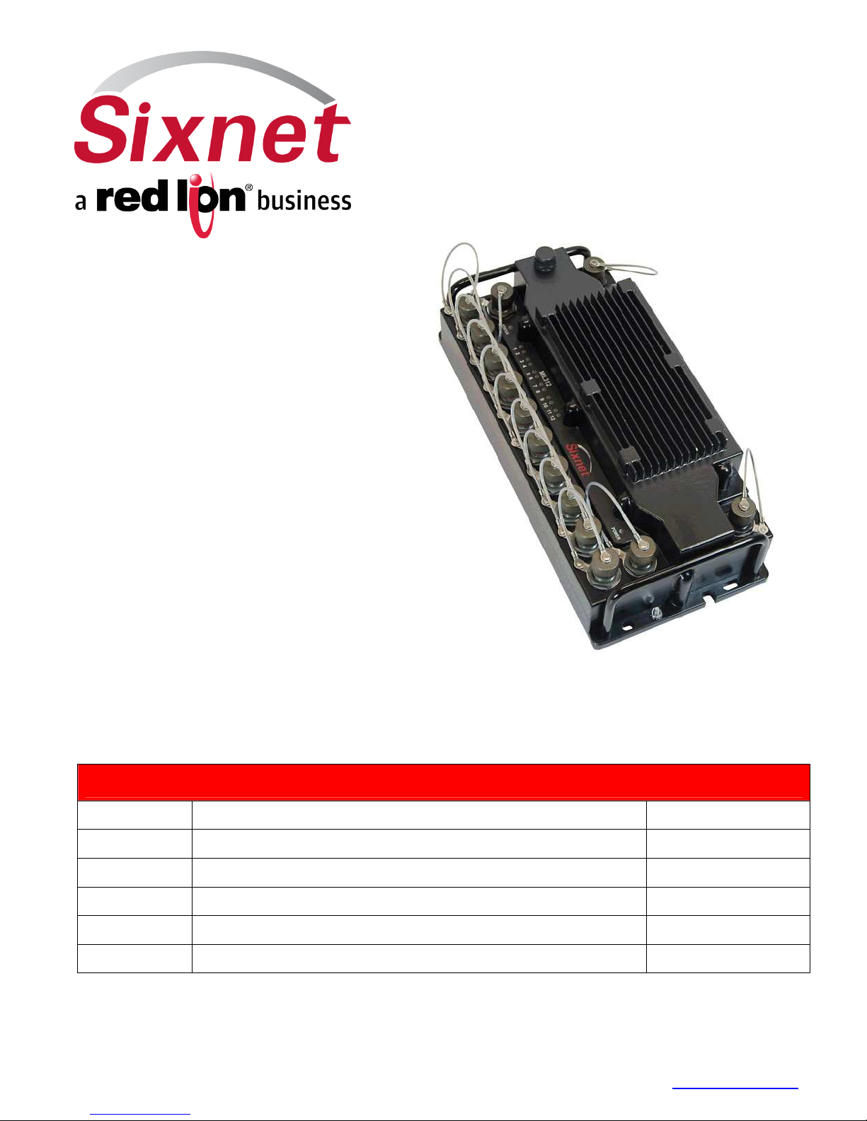
12-Port
Gigabit
IP67
Layer 3
USER MANUAL
Ethernet
Switch
Installation and Wiring Manual
Contents at a Glance:
Section 1 General Information Page 3
Section 2 Mechanical and Installation Page 7
Section 3 Power and Communication Wiring Page 9
Section 4 LEDs Page 14
Section 5 Pressure Vent Page 15
Section 6 Service and Contact Information Page 16
This manual applies to the following products:
• MIL312-1 IP67 managed Layer 3 Ethernet switch with 12 Gigabit ports
MIL312 Hardware Manual_Rev_02-14-13.docx Page 1 of 16 Last Revised: 14-Feb-13
Sixnet Technology Park •••• 331 Ushers Road •••• Ballston Lake, NY 12019 •••• USA •••• +1-518-877-5173 •••• [email protected]
Page 2

Sixnet Protected Technology Policy -
Sixnet protects your investment in Sixnet systems with longterm planned technology and our unique Protected Technology Policy. We will continue to support the
specified capabilities of standard Sixnet products for at least five years (twenty years for Industrial Managed
Switches). We plan each product improvement and new feature to be upward compatible with existing
designs and installations. Our goals are to make each new software release bring new power to your Sixnet
systems and have every existing feature, applications program and data file continue to work. We protect
your investment even further with a liberal five-year trade-in policy. Exchange standard products for
upgraded versions of the same product to take advantage of new features and improvements at any time
for five years. A prorated trade-in allowance will be given for your existing unit. Sixnet protects your longterm productivity with state-of-the-art planned technology and continued support.
Sixnet Statement of Limited Warranty -
Sixnet, manufacturer of Sixnet products, warrants to Buyer
that products, except software, manufactured by Sixnet will be free from defects in material and
workmanship. Sixnet's obligation under this warranty will be limited to repairing or replacing, at Sixnet's
option, the defective parts within one year of the date of installation, or within 60 months of the date of
shipment from the point of manufacture, whichever is sooner. Products may be returned by Buyer only after
permission has been obtained from Sixnet. Buyer will prepay all freight charges to return any products to
the repair facility designated by Sixnet. This limited warranty does not cover losses or damages which occur
in shipment to or from Buyer or due to improper installation, maintenance, misuse, neglect or any cause
other than ordinary commercial or industrial applications. In particular, Sixnet makes no warranties
whatsoever with respect to implied warranties of merchantability or fitness for any particular purpose. All
such warranties are hereby expressly disclaimed. No oral or written information or advice given by Sixnet or
Sixnet’s representative shall create a warranty or in any way increase the scope of this warranty. This
limited warranty is in lieu of all other warranties whether oral or written, expressed or implied. Sixnet's
liability shall not exceed the price of the individual units, which are the basis of the claim. In no event shall
Sixnet be liable for any loss of profits, loss of use of facilities or equipment, or other indirect, incidental or
consequential damages.
INSTALLATION WARNINGS -
These products should not be used to replace proper safety
interlocking. No software-based device (or any other solid-state device) should ever be designed to
be responsible for the maintenance of consequential equipment or personnel safety. In particular,
Sixnet disclaims any responsibility for damages, either direct or consequential, that result from the
use of this equipment in any application. All power, input and output (I/O) wiring must be in
accordance with Class I, Division 2 wiring methods and in accordance with the authority having
jurisdiction. Refer to section 1 for other important installation warnings.
FCC Statement
- This equipment has been tested and found to comply with the limits for a Class B digital
device, pursuant to Part 15 of the FCC Rules. These limits are designed to provide reasonable protection
against harmful interference in a residential installation. This equipment generates, uses and can radiate
radio frequency energy and, if not installed and used in accordance with the instructions, may cause
harmful interference to radio communications. However, there is no guarantee that interference will not
occur in a particular installation. If this equipment does cause harmful interference to radio or television
reception, which can be determined by turning the equipment off and on, the user is encouraged to try to
correct the interference by one or more of the following measures: Reorient or relocate the receiving
antenna; Increase the separation between the equipment and receiver; Connect the equipment into an
outlet on a circuit different from that to which the receiver is connected; Consult the dealer or an
experienced radio/TV technician for help.
Copyright & Trademarks -
Copyright 2013 Sixnet, LLC. All Rights Reserved.
Note: All information in this document is subject to change without notice.
MIL312 Hardware Manual_Rev_02-14-13.docx Page 2 of 16 Last Revised: 14-Feb-13
Sixnet Technology Park •••• 331 Ushers Road •••• Ballston Lake, NY 12019 •••• USA •••• +1-518-877-5173 •••• [email protected]
Page 3

Section 1
Overview
Basic
Operation
Performance
Specs
General Specifications
The Sixnet MIL312-1 is a 12 port industrial Ethernet managed switch designed to meet the
extreme requirements found in the toughest applications. It combines the high performance
and security of an enterprise-class switch with rugged packaging and protected circuitry to
meet the needs of the most demanding applications.
This manual will help you install and maintain these industrial Ethernet switches.
Installation of these switches is very easy and they will begin to operate as soon as they
are powered up. Though these are fully managed switches, they will act as unmanaged
until they are configured otherwise. Refer to the separate software manual or management
guide for configuration of the advanced networking functionality and security.
Note: This manual only covers the installation and wiring of these switches. Refer
to the separate Software User Manual for details on configuring and using any of
the management functions such as SNMP, RSTP, IGMP, port mirroring, etc.
Unlike an Ethernet hub that broadcasts all messages out all ports, these industrial Ethernet
switches will intelligently route Ethernet messages only out the appropriate port. The major
benefits of this are increased bandwidth and speed, reduction or elimination of message
collisions, and deterministic performance when tied with real-time systems.
These switches support 10BaseT (10 Mbps), 100BaseT (100 Mbps) and 1000BaseT (1000
Mbps) on 12 ports. Each of these ports independently and automatically senses the speed
and duplex for best performance. They also offer auto-crossover and auto-polarity to
assure a proper link with either straight or crossed wired cables or even when the cable is
incorrectly wired.
The switch has the following performance specifications. Note: All specifications are
subject to change. Consult factory for latest information.
ETHERNET PERFORMANCE
12 10/100/1000 Ethernet ports
Auto-negotiation (speed/duplex) and auto-crossover
Non-blocking, store and forward, wire-speed
Switching capacity and forwarding rate: 12.8 Gbps / 9.5 Mpps
MAC address table size: 16K
Jumbo frame: 9K
Ethernet isolation: 1500 Vrms 1 minute
Connector: MIL-STD-38999 series III receptacle
ETHERNET COMPLIANCE
IEEE 802.3 (Original Ethernet 10Mbps)
IEEE 802.3u (Fast Ethernet 100Mbps)
IEEE 802.3z (Gigabit Ethernet 1000Mbps)
IEEE 802.3x (Full-Duplex with Flow Control)
Refer to product data sheet for complete list
MIL312 Hardware Manual_Rev_02-14-13.docx Page 3 of 16 Last Revised: 14-Feb-13
Sixnet Technology Park •••• 331 Ushers Road •••• Ballston Lake, NY 12019 •••• USA •••• +1-518-877-5173 •••• [email protected]
Page 4

POWER INPUT
Connector: MIL-STD-38999 Series III receptacle with shell size A, style 98, 3 pin
contacts and A keying
Input voltage range: 18-36 VDC (continuos), 28 VDC Nominal
Input power: 35 W (typical under full load)
Reverse polarity protection
Meets MIL-STD-704 and MIL-STD-1275 for power protection
Surge protection: 100 volts for 1 second
Transient protection: 15,000 watts peak
Spike protection: 5,000 watts (10x for 10 uS)
or 250 volts (50x for 100 uS)
ENVIRONMENTAL
Operating temperature: -40 to +75°C (cold startup at -40°C)
Storage temperature: -40 to +85 °C
Humidity (non-condensing) 5 to 95% RH
Vibration, shock and free fall per MIL-STD-810F and IEC68-2-6, -27 and -32
Vent plug for high altitude operation
PHYSICAL
Dimensions (L x W x H) 13 x 6 x 3.75” (330 x 152 x 95 mm)
Weight (including caps) 9.8 lbs (4.45 Kg)
IP67 dust, oil and water-tight package protection
STANDARDS COMPLIANCE
FCC part 15 / ICES-003; EN55022; IEC61326-1
MIL-STD-461F for EMC performance
MIL-STD-810F and MIL-STD-202F/G for environmental performance
MIL-STD-704A/E/F and MIL-STD-1275A/B/D for power protection
SWITCHING FEATURES
Flow control: IEEE 802.3x (Full Duplex) & Back-Pressure (Half Duplex)
Spanning Tree Protocol (STP per IEEE 802.1D) plus
o
IEEE 802.1w Rapid Spanning Tree Protocol (RSTP)
o
IEEE 802.1s Multiple Spanning Tree Protocol (MSTP)
o
BPDU forwarding and filtering
Virtual Local Area Networks (VLANs)
o
802.1Q tag-based with 256 VLANs and 4K VLAN ID
o
802.1v protocol and port-based VLAN
o
Voice and Private VLAN
o
QVRP and Q-in-Q (double tagging)
Link Aggregation Control Protcol (LACP per IEEE 802.3ad)
o
Static trunk (8 trunks and up to 8 ports per trunk)
o
Traffic load balancing
Internet Group Management Protocol (IGMP)
o
IGMP v1, v2 and v3 with up to 255 multicast groups
o
IGMP snooping and querying
o
Immediate leave and leave proxy
o
Throttling and filtering
Multicast VLAN Registration (MVR)
IEEE 802.1ab Link layer Discovery Protocol (LLDP)
Quality of Service (QoS) with 4 priority queues
o
Scheduling schemes: WRR and Strict priority
o
CoS per IEEE 802.1p and IP DSCP-based
o
DiffServ (DS): ingress, egress and remarking
Rate limiting (ingress and egress)
o
64Kbps to 100/1000Mbps
o
Per port CoS
MIL312 Hardware Manual_Rev_02-14-13.docx Page 4 of 16 Last Revised: 14-Feb-13
Sixnet Technology Park •••• 331 Ushers Road •••• Ballston Lake, NY 12019 •••• USA •••• +1-518-877-5173 •••• [email protected]
Page 5

SECURITY
Enable / disable ports
Port security (MAC-based): static and dynamic
DHCP Snooping and Option 82
IP Source Guard
IEEE 802.1x Network Access Control
o
Port-based with single or multiple host mode
o
Authentication: EAP-MD5, PEAP, TLS, TTLS
o
MAC and web authentication
o
Guest VLAN and Auto VLAN assignment
RADIUS and TACACS AAA
o
Authentication, Accounting and Authorization
o
5 servers for RADIUS, 1 server for TACACS
o
Encryption: MD5, TLS, TTLS, TACACS AAA/3.0
Access Control List (ACL)
o
IP and MAC-based
o
VLAN and TCP/UDP port
Storm Control for broadcast and multicast messages
HTTPS/SSL for secure Web access
SSH v1.5/2.0 for secure Telnet access
SNMPv3 authentication and encryption
Username and password authentication
Management access filtering
MANAGEMENT AND MONITORING
RS232 console port via MIL-STD-38999 series III connector w/ shell size A, style 35,
6 contacts & A keying
IP Address assignment: Static, DHCP and BOOTP
CLI (Command Line Interface) via console or Telnet
Web interface (HTTP/HTTPS/SSL)
SNMP v1, v2, v3 (Simple Network Management Protocol)
SNMP Traps for event notification
RMON (Remote Monitoring): Groups 1, 2, 3 and 9
sFlow network-wide traffic monitoring
Dual firmware update system
Configuration download and upload
Software upgrade via TFTP
Port mirroring
Event / Error / System log
o
Local flash
o
Remote server via system log (Syslog RFC 3164)
o
SMTP (RFC 821) email alarming
Network Time Protocol for time synchronization
o
SNTP (RFC 2030) and NTP (RFC 1305)
DNS (Domain Name Server) client
Universal Plug and Play (UPnP)
IEEE 802.3ah OAM (Operational Administration Maintenance)
o
Banner commands
MIL312 Hardware Manual_Rev_02-14-13.docx Page 5 of 16 Last Revised: 14-Feb-13
Sixnet Technology Park •••• 331 Ushers Road •••• Ballston Lake, NY 12019 •••• USA •••• +1-518-877-5173 •••• [email protected]
Page 6
WARNING
WARNING
WARNING
Safety
Warnings
ROUTING FEATURES
Host table: 8K
Route table: 8K
Static route table: 512
Multicast table: 1L
Unicast routing
Static unicast routes
RIP v1/v2
OSPF
BGP
Multicast routing
PIM-DM
PIM-SM
IGMP v1/v2/v3
IGMP v3 proxy
IP Redundancy
Proxy ARP
UDP Helper
WARRANTY
5 years on design and manufacturing defects
Strictly abiding by these warnings will help ensure the safe installation, startup and
operation of the switch.
INSTALL THE SWITCH IN ACCORDANCE WITH ALL LOCAL AND NATIONAL
ELECTRICAL CODES.
LIGHTNING DANGER: DO NOT WORK ON EQUIPMENT DURING PERIODS OF
(EXPLOSION
HAZARD)
(EXPLOSION
HAZARD)
(EXPLOSION
HAZARD)
LIGHTNING ACTIVITY.
SUBSTITUTION OF COMPONENTS MAY IMPAIR SUITABILITY FOR CLASS 1,
DIVISION 2 (ZONE 2).
WHEN IN HAZARDOUS LOCATIONS, DISCONNECT POWER BEFORE REPLACING
OR WIRING UNITS.
DO NOT DISCONNECT EQUIPMENT UNLESS POWER HAS BEEN SWITCHED OFF
OR THE AREA IS KNOWN TO BE NONHAZARDOUS.
MIL312 Hardware Manual_Rev_02-14-13.docx Page 6 of 16 Last Revised: 14-Feb-13
Sixnet Technology Park •••• 331 Ushers Road •••• Ballston Lake, NY 12019 •••• USA •••• +1-518-877-5173 •••• [email protected]
Page 7
Section 2 Mechanical Dimensions and Installation
Overview
2.116" [53.75mm]
1.187" [30.16mm]
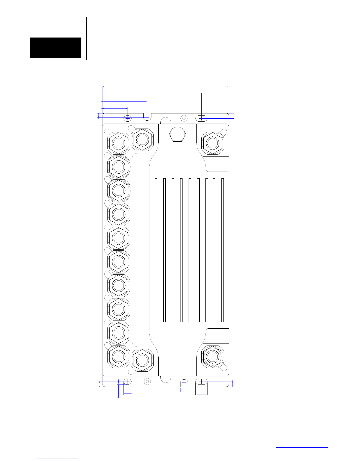
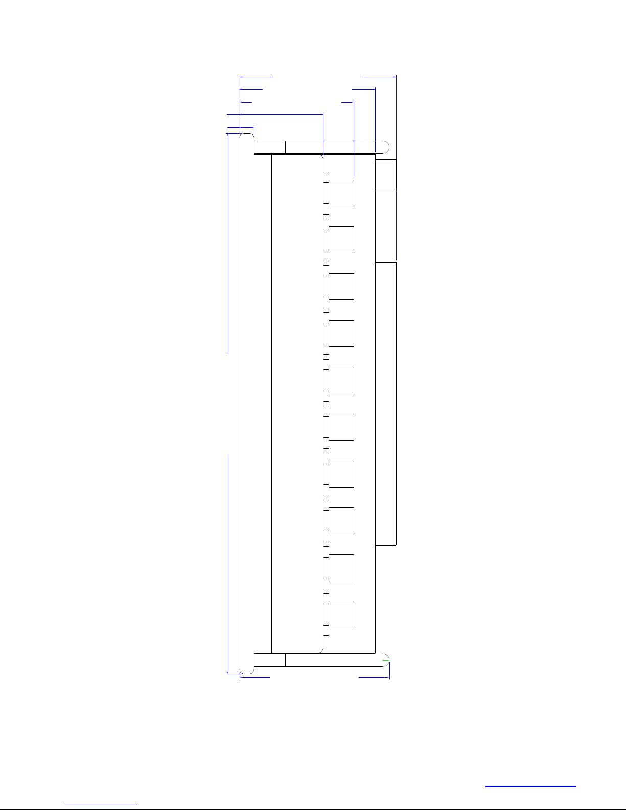
The switch is designed to be mounted to any flat surface. It is recommended to use thermal
grease or a gap pad between the MIL312 unit and the surface it is mounted on. The MIL312
case is designed to act as a heat sink and this will ensure cooler operation of the unit.
5.980" [151.89mm]
4.687" [119.06mm]
Gig Ports
0.212" [5.40mm]
Console
Vent
2
1
0.250" [6.35mm]
3
4
5
6
7
8
9
10
11
0.250" [6.35mm]
0.275" [6.98mm]
MIL312 Hardware Manual_Rev_02-14-13.docx Page 7 of 16 Last Revised: 14-Feb-13
Sixnet Technology Park •••• 331 Ushers Road •••• Ballston Lake, NY 12019 •••• USA •••• +1-518-877-5173 •••• [email protected]
12
0.375" [9.52mm]
0.375" [9.52mm]
Power
0.250" [6.35mm]
0.575" [14.61mm]
Page 8
2.004" [50.90mm]
0.350" [8.89mm]
3.754" [95.35mm]
3.254" [82.65mm]
2.744" [69.70mm]
12.980" [329.69mm]
3.600" [91.44mm]
MIL312 Hardware Manual_Rev_02-14-13.docx Page 8 of 16 Last Revised: 14-Feb-13
Sixnet Technology Park •••• 331 Ushers Road •••• Ballston Lake, NY 12019 •••• USA •••• +1-518-877-5173 •••• [email protected]
Page 9
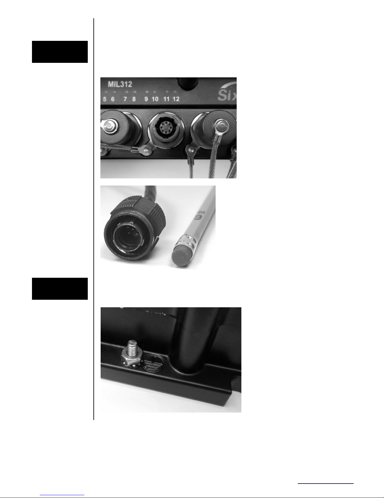
Section 3 Power and Communication Connections
Overview
Typical
MIL-STD-38999
Connectors
(shown with
tethered plugs)
Typical
MIL-STD-38999
Plug
The switch features 38999 Series III style connectors which meet or exceed the MIL-STD38999 standard. All these connectors have EMI shielding, ESD protection, plus moisture
and corrosion resistance. All mating connectors will self-lock with one 360 degree turn of
the coupling nut.
(not typically
supplied with
switch)
Grounding
Use the provided 8-32 ground stud to connect the switch to a suitable safety, chassis or
earth ground. Use of heavy gauge (at least 16 AWG) grounding wire is recommended.
Make sure to follow your local or national codes for the proper ground connection.
Chassis
Ground
Connection
Point
MIL312 Hardware Manual_Rev_02-14-13.docx Page 9 of 16 Last Revised: 14-Feb-13
Sixnet Technology Park •••• 331 Ushers Road •••• Ballston Lake, NY 12019 •••• USA •••• +1-518-877-5173 •••• [email protected]
Page 10
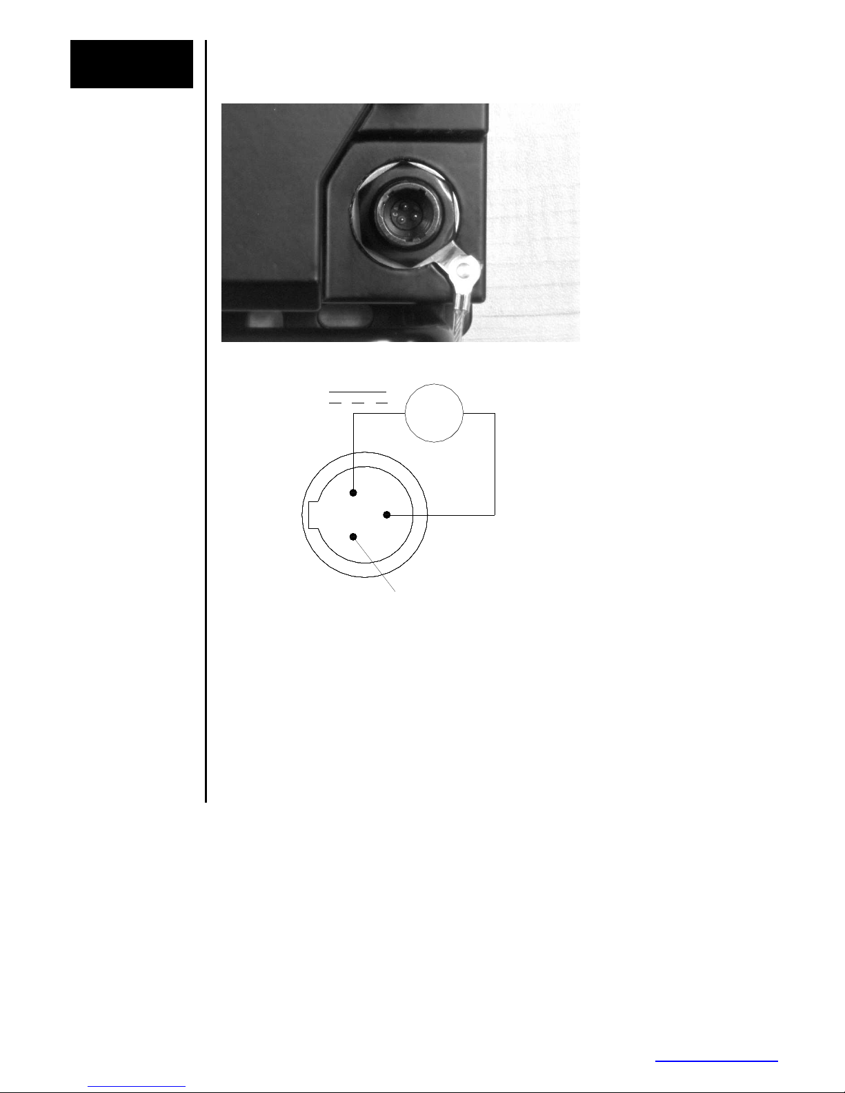
Power
28 VDC
Receptacle
Power
Receptacle
The switch requires a nominal voltage of
connections as shown in the diagram below.
(18-36 VDC Range). Make the power
DC Supply
--
++
Power
Receptacle
Pinout
Shell=A, Insert=98, Contacts=P, Keying=A
Recommended
Plug
Model # D38999/26WA98SA
(w/ socket contacts and A keying)
A
B
C
No Connection
Receptacle:
MIL312 Hardware Manual_Rev_02-14-13.docx Page 10 of 16 Last Revised: 14-Feb-13
Sixnet Technology Park •••• 331 Ushers Road •••• Ballston Lake, NY 12019 •••• USA •••• +1-518-877-5173 •••• [email protected]
Page 11
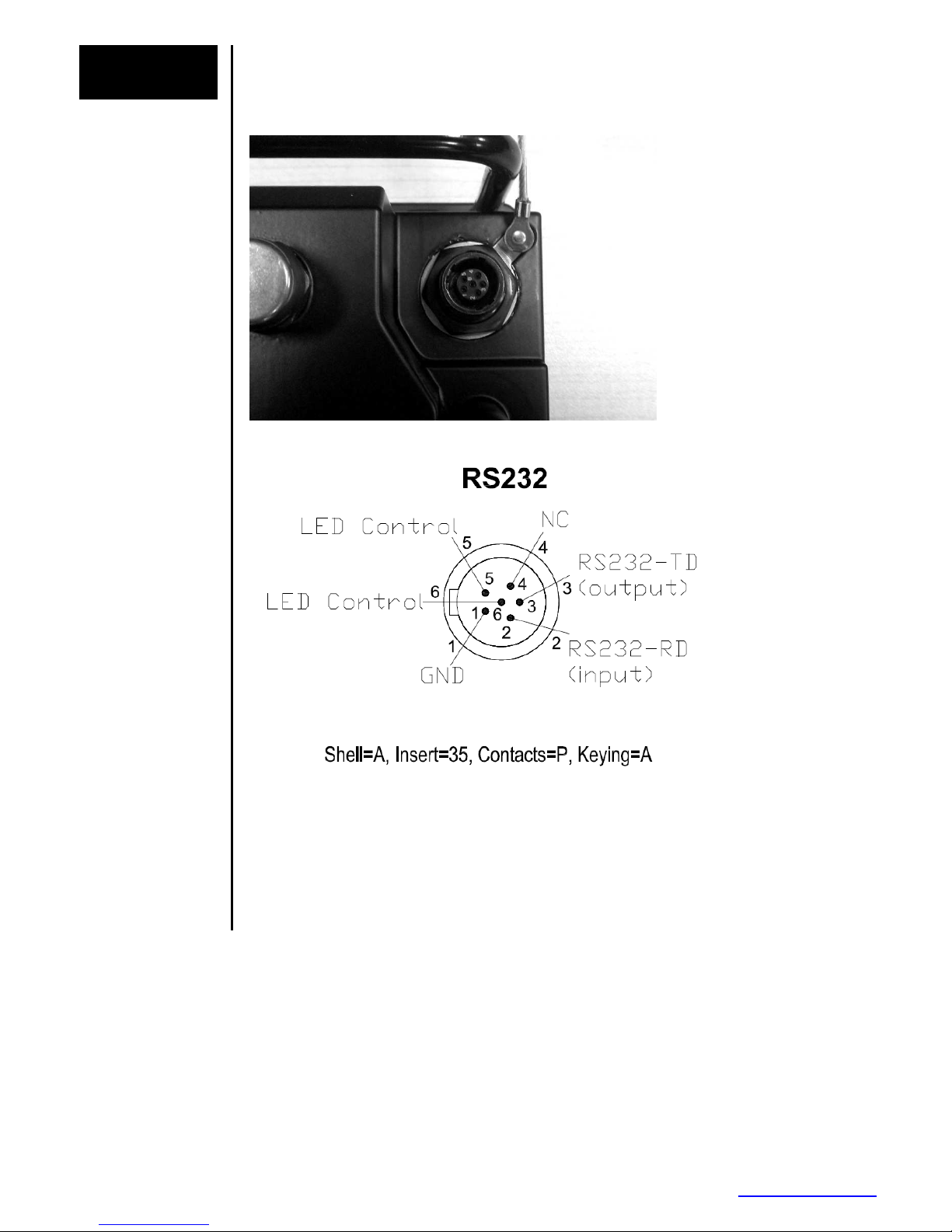
Console
Receptacle
The switch offers a RS232 serial port for accessing the local management interface. Once
you have made a physical connection refer to the software user manual on how to access
the switch via this console port.
Console
Receptacle
Console
Receptacle
Pinout
Shorting out pins 5 and 6 on the RS232 connector will turn off all LEDs while
LED Control
continuing regular switch operation. Leave pins 5 and 6 open for normal LED
function.
Recommended
Plug
Model # D38999/26WA35PA
(w/ pin contacts and A keying)
MIL312 Hardware Manual_Rev_02-14-13.docx Page 11 of 16 Last Revised: 14-Feb-13
Sixnet Technology Park •••• 331 Ushers Road •••• Ballston Lake, NY 12019 •••• USA •••• +1-518-877-5173 •••• [email protected]
Page 12
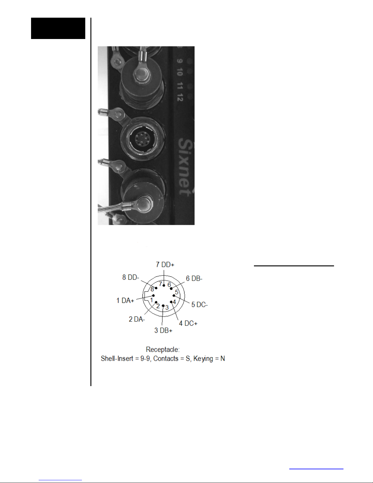
Ethernet
Ethernet
Recommended
Receptacle
Ethernet
Receptacle
The switch has 12 10/100/1000 Ethernet ports. These ports will auto-detect the speed and
duplex of the connection. The ports can be disabled or configured for fixed settings via one
of the management interfaces. See the software user manual for details.
Receptacle
Pinout
Plug
AERO AE90-365-BN9-9PN
Typical Pinout Connections
Pin-1 - - - TX + (For 10/100)
Pin-2 - - - TX – (For 10/100)
Pin-3 - - - RX + (For 10/100)
Pin-4 - - - TX + (For Gig)
Pin-5 - - - TX – (For Gig)
Pin-6 - - - RX – (For 10/100)
Pin-7 - - - RX + (For Gig)
Pin-8 - - - RX – (For Gig)
MIL312 Hardware Manual_Rev_02-14-13.docx Page 12 of 16 Last Revised: 14-Feb-13
Sixnet Technology Park •••• 331 Ushers Road •••• Ballston Lake, NY 12019 •••• USA •••• +1-518-877-5173 •••• [email protected]
Page 13

Wiring
Standards
Table
See chart below
EIA / TIA
Pin
568A
white / white /
1
green orange
green / orange /
2
white (green) white (orange)
white / white /
3
orange green
blue / blue /
4
white (blue) white (blue)
white / white /
5
blue blue
orange / green /
6
white (orange) white (green)
white / white /
7
brown brown
brown / brown /
8
white (brown) white (brown)
(Pair Colors may be solid and striped/color, or color with white stripe and white with color stripe)
EIA / TIA
568B or
AT&T 258A
BI=BI directional data RX=Receive Data TX=Transmit Data
10Base-T
10 Mbps
Cat3
TX+ TX+ TX D1+ BI DA+ BI DA+
TX- TX- TX D1- BI DA- BI DA-
RX+ RX+ RX D2+ BI DB+ BI DB+
N/A N/A BI D3+ N/A BI DC+
N/A N/A BI D3- N/A BI DC-
RX- RX- RX D2- BI DB- BI DB-
N/A N/A BI D4+ N/A BI DD+
N/A N/A BI D4- N/A BI DD -
100Base-TX
100 Mbps
Cat5
100Base-T4
100 Mbps
Cat3
100Base-T2
100 Mbps
Cat3
1000Base-T
1 Gbps
Cat5+
MIL312 Hardware Manual_Rev_02-14-13.docx Page 13 of 16 Last Revised: 14-Feb-13
Sixnet Technology Park •••• 331 Ushers Road •••• Ballston Lake, NY 12019 •••• USA •••• +1-518-877-5173 •••• [email protected]
Page 14
Section 4 LEDs
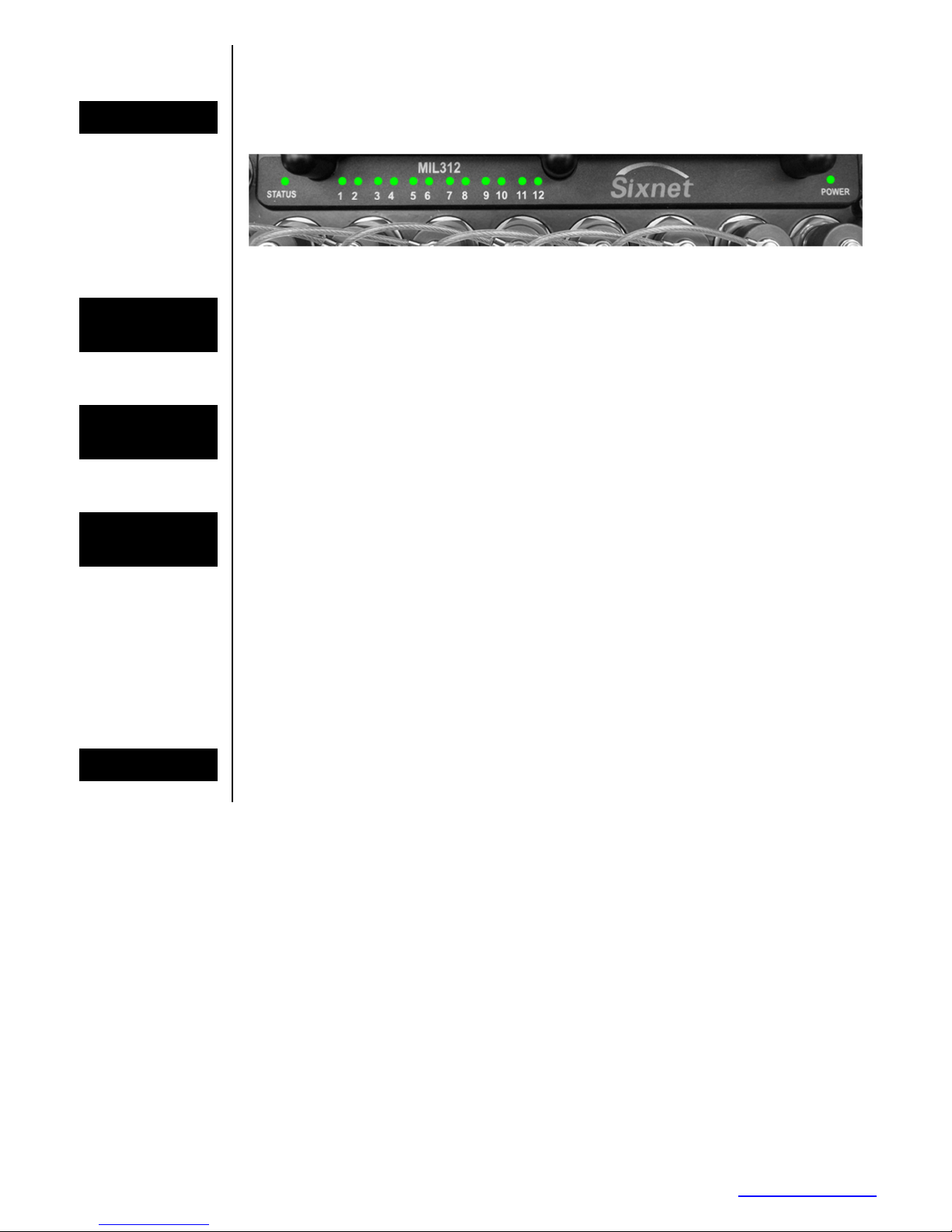
LED Location
Status LED
Power LEDs
Ethernet
LEDs
LED Blackout
The switch has a set of LEDs to indicate the status of various operating conditions as
defined below.
The Status LED indicates the overall health of the switch. It is normally ON solid green
indicating that no internal CPU or software problems are detected. It will flash green when
loading firmware and briefly on power up or reset. Otherwise, if it is OFF or amber for an
extended period of time then a problem is detected. In this case, please contact technical
support.
The Power LED will be on solid green when power is applied to the switch. In the event of a
power fault, the LED will turn to solid amber. The LED will also be solid amber during a
portion of the boot up sequence.
The switch has a set of LEDs to indicate the status of the Ethernet ports. Each LED is
labeled with the number of the port it represents. They function as follows:
Solid Green = 1000 Mbps linked detected but no Ethernet activity.
Flashing Green = 1000 Mbps linked detected with Ethernet activity.
Solid Orange = 10/100 Mbps linked but no Ethernet activity.
Flashing Orange = 10/100 Mbps linked detected with Ethernet activity.
OFF = No link detected.
The switch is equipped with the capability to toggle the LEDs from an active state to an
inactive state. See Console Receptacle Pinout above or refer to data sheet for more
information.
Typical LED Location
MIL312 Hardware Manual_Rev_02-14-13.docx Page 14 of 16 Last Revised: 14-Feb-13
Sixnet Technology Park •••• 331 Ushers Road •••• Ballston Lake, NY 12019 •••• USA •••• +1-518-877-5173 •••• [email protected]
Page 15
Section 5 Pressure Vent
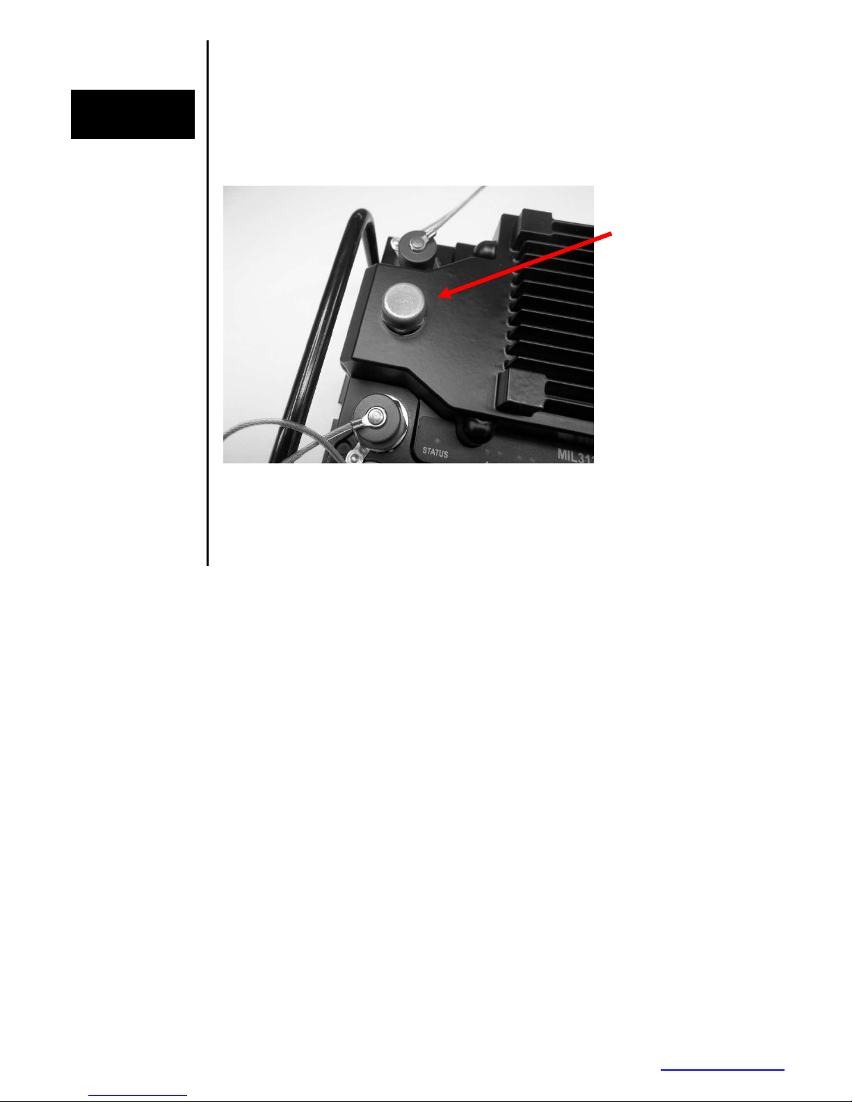
Pressure
Vent
Without a pressure ventilation system the pressure differential that can occur due to
temperature or altitude changes can result in condensation. To prevent this, the switch
incorporates a pressure vent that adjusts the internal air pressure to match the
surrounding (external) pressure. At the same time the vent is IP67 rated and will not let
moisture into the switch. Assembled
Pressure Vent
Pressure Vent
Characteristics
Air flow rate: 0,4 l/min at 0, bar ∆P to 5,0 l/min at 1 bar ∆P
Point of water entry: >1,5 bar
Temperature resistance: -40°C to +120°C (in assembled state)
MIL312 Hardware Manual_Rev_02-14-13.docx Page 15 of 16 Last Revised: 14-Feb-13
Sixnet Technology Park •••• 331 Ushers Road •••• Ballston Lake, NY 12019 •••• USA •••• +1-518-877-5173 •••• [email protected]
Page 16

Section 6 Service Information
Sixnet
Service
Information
Product
Support
We sincerely hope that you never experience a problem with any
need service, call Sixnet at (518) 877-5173 and ask for Technical Support. A trained
specialist will help you to quickly determine the source of the problem. Many problems are
easily resolved with a single phone call. If it is necessary to return a unit to us, an RMA
(Return Material Authorization) number will be given to you.
Sixnet tracks the flow of returned material with our RMA system to ensure speedy service.
You must include this RMA number on the outside of the box so that your return can be
processed immediately.
The applications engineer you are speaking with will fill out an RMA request for you. If the
unit has a serial number, we will not need detailed financial information. Otherwise, be sure
to have your original purchase order number and date purchased available.
We suggest that you give us a repair purchase order number in case the repair is not
covered under our warranty. You will not be billed if the repair is covered under warranty.
Please supply us with as many details about the problem as you can. The information you
supply will be written on the RMA form and supplied to the repair department before your
unit arrives. This helps us to provide you with the best service, in the fastest manner.
Normally, repairs are completed in two days. Sometimes difficult problems take a little
longer to solve.
If you need a quicker turnaround, ship the unit to us by air freight. We give priority service to
equipment that arrives by overnight delivery. Many repairs received by mid-morning (typical
overnight delivery) can be finished the same day and returned immediately.
We apologize for any inconvenience that the need for repair may cause you. We hope that
our rapid service meets your needs. If you have any suggestions to help us improve our
service, please give us a call. We appreciate your ideas and will respond to them.
For Your Convenience:
Please fill in the following and keep this manual with your Sixnet system for future
reference:
Serial #:__________________ Date Purchased: ___________________
Purchased From:______________________________________________
To obtain support for Sixnet products:
Latest product info: http://www.sixnet.com
Phone: +1 (518) 877-5173
Fax: +1 (518) 877-8346
E-mail: mailto: [email protected]
Mailing address:
Sixnet Technology Park, 331 Ushers Road, Ballston Lake, NY 12019
product. If you do
MIL312 Hardware Manual_Rev_02-14-13.docx Page 16 of 16 Last Revised: 14-Feb-13
Sixnet Technology Park •••• 331 Ushers Road •••• Ballston Lake, NY 12019 •••• USA •••• +1-518-877-5173 •••• [email protected]
 Loading...