

Page 1
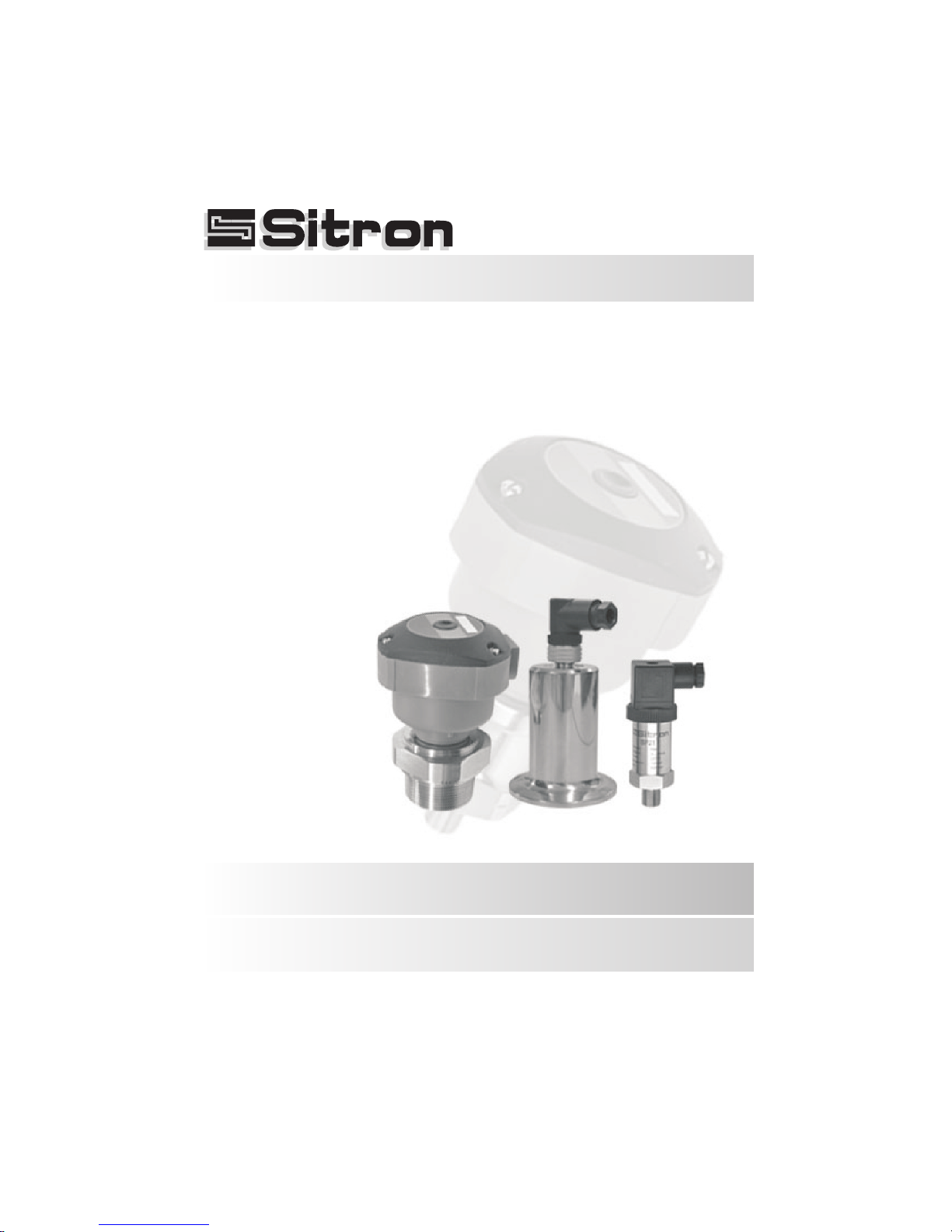
USER MANUAL
Installation, Operation and Maintenance Manual
Pressure Transmitters
Series: SP
Page 2

02
Contents
Introduction . . . . . . . . . . . . . . . . . . . . . . . . . . . . . . . . . . . . . . . . . . . . . . . . . 3
Models & Dimension . . . . . . . . . . . . . . . . . . . . . . . . . . . . . . . . . . . . . . . . . . 4
Electrical Connection. . . . . . . . . . . . . . . . . . . . . . . . . . . . . . . . . . . . . . . . . . 7
Mounting Notes . . . . . . . . . . . . . . . . . . . . . . . . . . . . . . . . . . . . . . . . . . . . . 10
Installation . . . . . . . . . . . . . . . . . . . . . . . . . . . . . . . . . . . . . . . . . . . . . . . . . 11
Calibration . . . . . . . . . . . . . . . . . . . . . . . . . . . . . . . . . . . . . . . . . . . . . . . . . 13
Handling . . . . . . . . . . . . . . . . . . . . . . . . . . . . . . . . . . . . . . . . . . . . . . . . . . 14
Technical Specification . . . . . . . . . . . . . . . . . . . . . . . . . . . . . . . . . . . . . . 15
Trouble Shooting . . . . . . . . . . . . . . . . . . . . . . . . . . . . . . . . . . . . . . . . . . . . 23
Ordering Information . . . . . . . . . . . . . . . . . . . . . . . . . . . . . . . . . . . . . . . . 24
Warranty . . . . . . . . . . . . . . . . . . . . . . . . . . . . . . . . . . . . . . . . . . . . . . . . . 25
Sitron-USA - Phone (516) 935-8001 / Fax (800) 516-1656
Page 3
03
Introduction
Characteristics
The SP Series of pressure transmitters are designed to measure the level or pressure of
various industrial processes.
Models can be mounted with various threaded or flanged process connections. All
models are available with 4..20mA (2 wire) output (or voltage outputs). The SP/FA line
coms with an integrated Zero and Span adjustment. All units offer excellent stability,
repeatibility, accuracy and temperature compensation. HART communications protocol
is also available for many models.
Each model in this series is offered in pressure ranges that are suitable for various types
of application requirements such as for; liquids, gases, areas with limited space, food
industry, chemical industry or areas that feature aggressive mediums or waste fluids with
varying degrees of suspended solids.
Technology
The SP series utilize the principle of the alteration of resistance or capacitance. The SP
Series is available with sensing elements of either 316 Stainless Steel, ceramic
piezoresistive diaphragms or thick filmed ceramic diaphragms (for more aggressive
mediums or applications).
The external pressure of the medium induces a dislocation of electrical load that
accumulates on the opposite surface of the diaphragm, resulting in an output signal that is
proportional to the pre-calibrated pressure range of the sensor. The electronics converts
this information into either a 4...20mA(2 wire) output signal (standard) or a 1 to 5V (3 wire
optional per custom order), which is directly proportional to the applied pressure of the
process.
Small, robust and easy to install
Reliable measurement of level and pressure.
HART Communications Protocol is available (for most models)
Available in a wide range of process connections: Threaded, Flanged or Sanitary
SP Series
Pressure Transmitter
Pressure range up to 1000 Bar (14500 PSI) depending on the model
Page 4
04
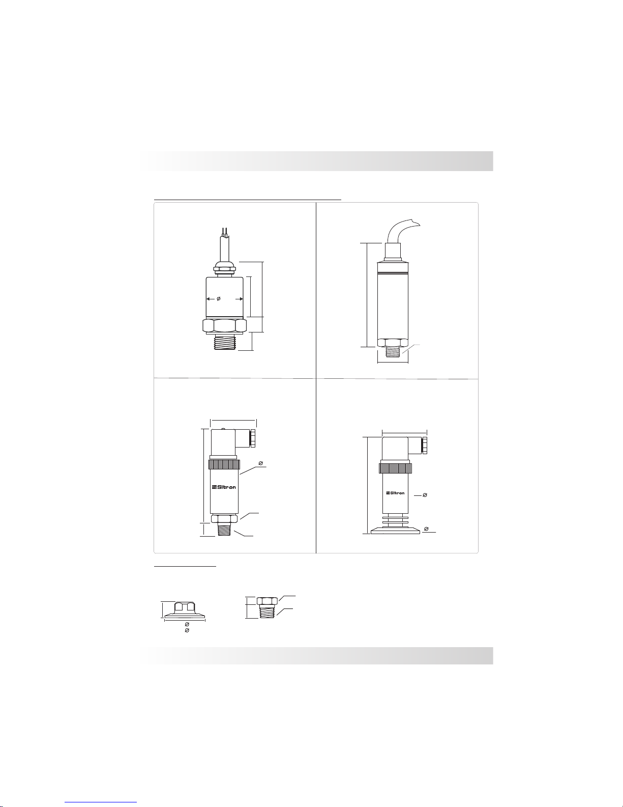
Models & Dimensions
SP21
103
1/4”NPT/BSP
34
Hex.15/16”
15
34
Threaded
Pressure transmitters models (unit: mm)
26.5
37
12.5
9.5
23,5
51
101
34
26.5
2” Tri-clamp
1/4” to ½”
1/4” to 1.1/2”
or 2” TC
Hex. 1”
19mm
10mm
1/2”NPT/BSP
1.1/2”
50.8
2”
64
25mm
SP21 Adapter
26.5
Ø
111
SP68
NPT/BSP
NPT/BSP
SP30
SP10
Page 5

05
Models & Dimensions
SP96 (unit: mm)
Standard
1 ½ or 2” TC
NPT/BSP
38
83
38
50
28
84
19
Hex.
72
93
36
35
DIN connector M12 connector
1 ½”
50.8
2”
64
1 ½”
50.8
2”
64
NPT/BSP
Standard
1 ½ or 2” TC
103
19
87
1 ½”
50.8
2”
64
35
36
M12 connector
Threaded
1 ½ or 2” TC
NPT/BSP
SP98 (unit: mm)
93
29
Hex. 1 1/2”
BSP / NPT
Hex. 1 5/8”
1” BSP / NPT
29
77
SP81
M12 connector
Page 6

06
42
1 ½”
50,8
2”
64
77
89
44
19
Hex.1 5/8”
NPT/BSP
80
SP98FA with Housing
Threaded 1 ½ or 2” TC
Threaded 1 ½ or 2” TC
31
37
77
89
NPT/BSP
1 ½”
50,8
2”
64
80
SP96FA with Housing
Models & Dimensions
Threaded Connections
3/4”
1 ½”
1 ½”
1 ½”
2 ½”
2 ½”
1”
2”
2”
2”
3”
1”
1,75º
Tri-Clamp Connection Flange Connections
Process Connections
TC Connection
ANSI 150#
ANSI 300#
Rubber Seal
Process Connection
NPT
BSP
FF
RF
Page 7

2
4
Input
Active
+
-
1
4 ... 20 mA
+
_
2
24Vdc
4...20mA (2 wires)
Active
4
2
1
3
DIN 43650 connector
2 and 3 wires
1
3
-
+
Out
Passive
4...20mA
4...20mA (2 wires)
Passive
1
-
4...20mA
Electrical Connections
1...5Vdc
+
Supply
3
4
Supply
1...5Vdc (3 wires)
2
Out
+
-
1
2
43
Pressure
Transmitter
+
_
2
07
M12 connector
2 and 3 wires
1
-
+
Out
2
3
1
+
S
_
Pressure
Transmitter
Pressure
Transmitter
Page 8
08
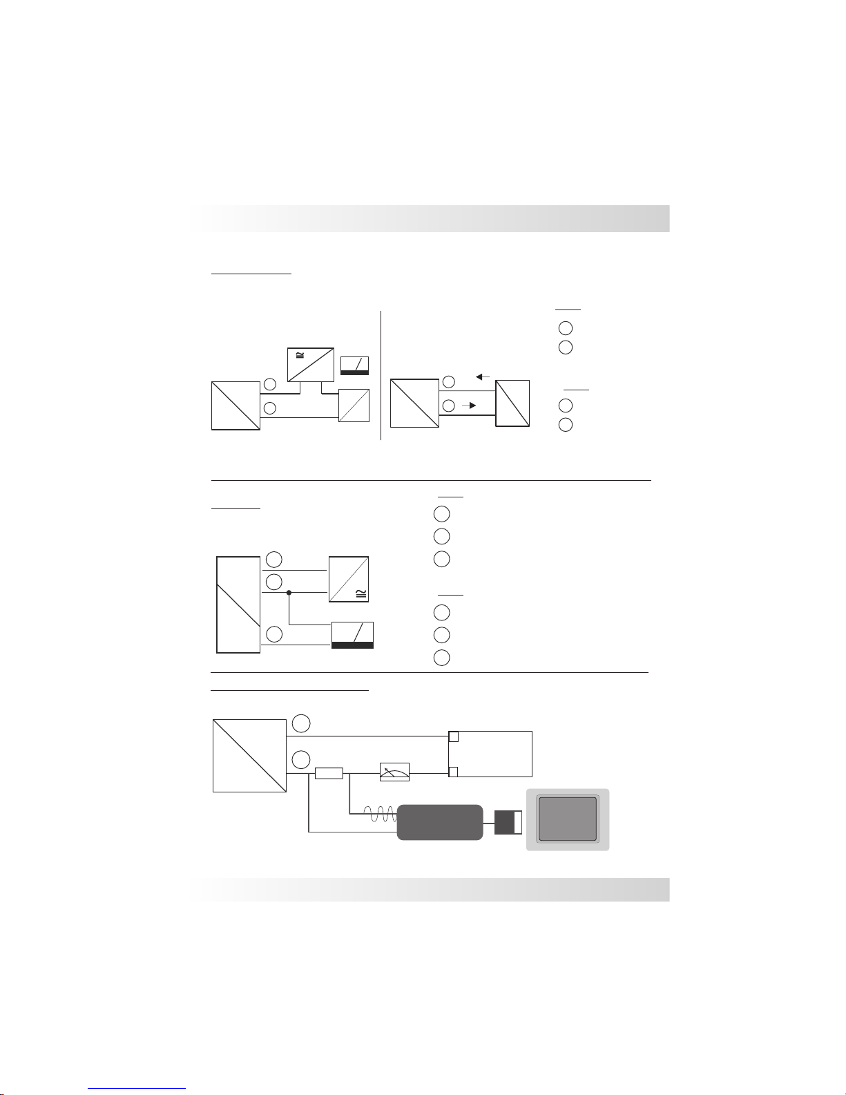
Electrical Connections
‘
2
3
1
+
S
_
+
-
1...5Vdc
Pressure
transmitter
Supply
Vdc
Red (+)
Green (-)
SP10 & SP68
2
1
Red (+)
Black (-)
SP10
SP68
HART Modem connection
4...20mA (2 wires)
Passive
+
-
1
Supply
+
_
2
4...20mA
Passive
Input
Active
+
-
1
4 ... 20mA
+
_
2
24Vdc
4...20mA (2 wires)
Active
2
1
3
2
1
Red (+)
Black (-)
Yellow (Out) 3 wires
SP68
3
2
1
Red (+)
Green (-)
Yellow (Out) 3 wires
SP10
4...20mA
Pressure
transmitter
Pressure
transmitter
PC Software
+
2
_
1
Transmitter
®
25
0
?
Padrão Hart modem
PC
+
-
•
•
USB
Power
Supply
HART
Modem
4...20mA
Page 9
09
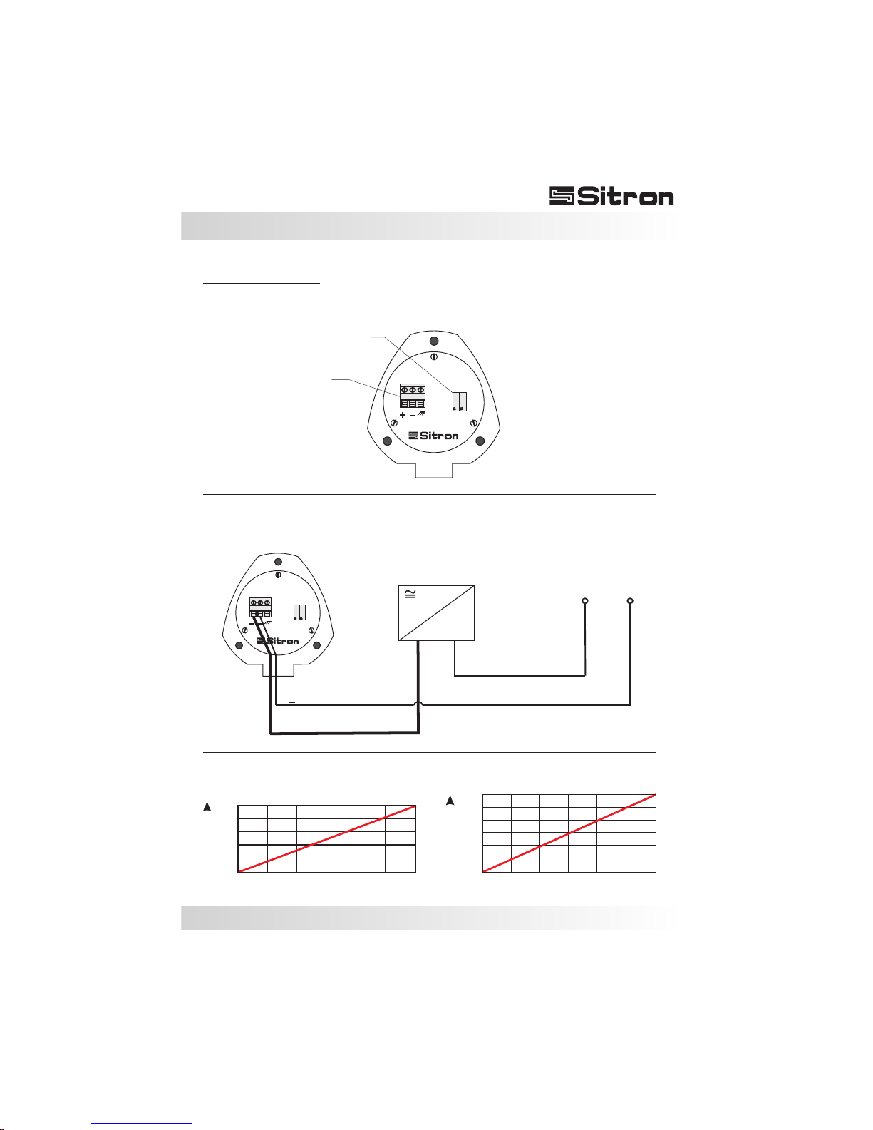
SP96FA & SP98FA
-
Supply
+
+
4...20mA
12 15 18 21 24 27 30 [V]
0
Load max. [Ù]
500
400
300
200
100
SP96FA
0
1200
1000
800
600
400
200
Load max. [Ù]
12 16 20 24 28 32 36[V]
SP98FA
Z
S
Z
S
Zero & Span adjustment
Supply
Load impedance
4...20mA (2 wires)
Electrical Connections
Page 10
10
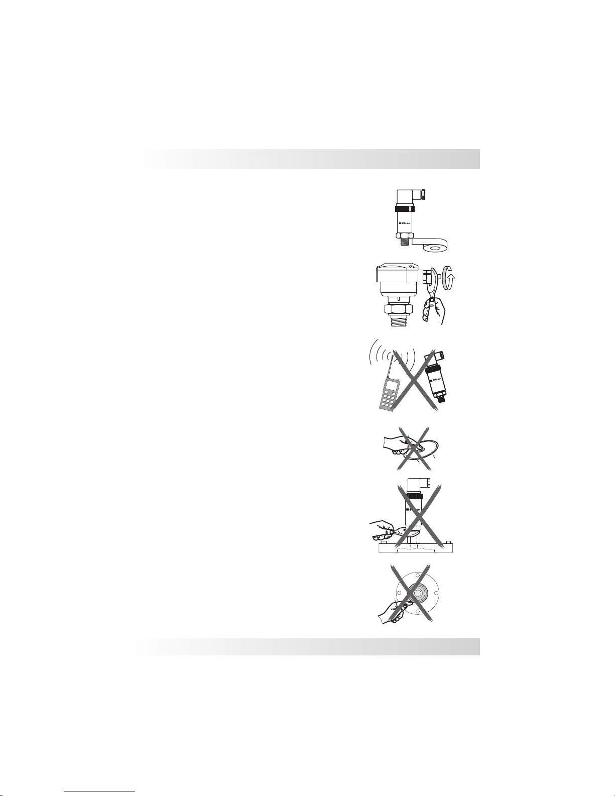
1) Use PTFE tape or o'rings to seal the system.
2) Before installing, make sure the cable connections are
correct and that the line voltage is compatible with the
specifications of the equipment. Use reliable cables and
make sure that they are grounded. Shielded cables
prevent interference and changes in the eletronic signal,
protecting against false measurement output. Avoid
radio frequency interference as it may also cause false
signals and even create a possible malfunction of the
tr a n smitte r. Wh e n possibl e , ke ep h and h eld
communication equipment away from the SP transmitter.
3) Care should be taken to prevent deformities in the
membrane. You should also be careful not to touch or let
any other object touch the membrane of the sensor
during installation (this does not apply to the units with
ceramic sensing elements) . Any deformity to the surface
of the 316SS silicone filled membrane will damage the
sensor and impair its operation.
Transmitters with cable gland:
Tighten the cable gland as much as possible so that the
cable is securely in place and cannot be pulled through
the cable gland. This will help insure that no moisture is
able to infiltrate into the housing. Don´t forget to attach
the housing cover and tighten all three screws into
position so that there is no infiltration.
4) Protect the transmitter against rain and do not expose it
to excessive heat. Respect the working temperature and
the class protection specified for use.
5) Before installation, for security reasons, make sure the
tank or pipe is empty and without pressure.
6) For transmitters with sealing:
Under no circunstances should you remove the
transmitter seal. Avoid flexing the membrane with your
hands and keep it protected until the installation.
Mounting Notes
Page 11
11
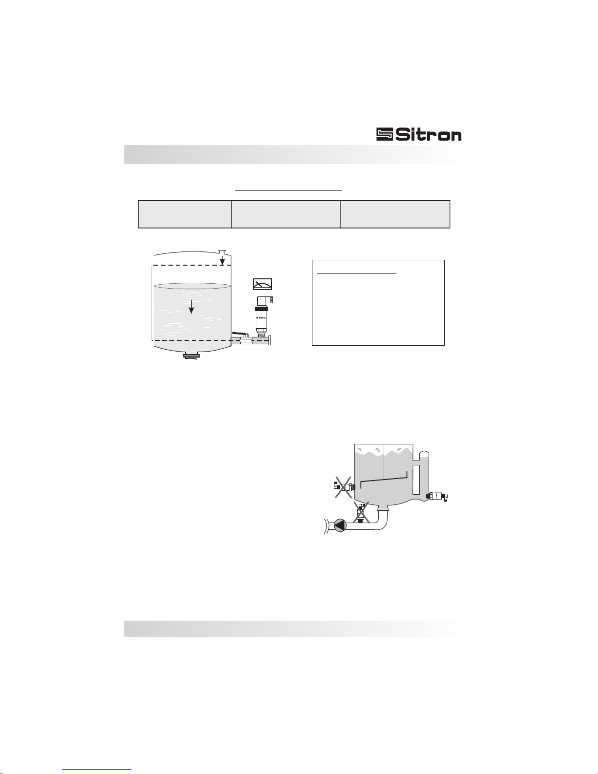
The transmitters can be installed in various
positions, but the following needs to be taken into
account: For level measurement the installation
should be at the base of the tank or at the point of
minimum level measurement (fig.1). This means
that the reference point for the base measurement
will become the point at which the sensor is
installed which will not necessarily be at the
bottom of the tank.
It is advisable to install a blocking valve between
the transmitter and the connection to perform
maintenance without having to stop the process.
Avoid installing in the tank outlet or near shaker
where there is pressure pulses thus preventing
rapid changes in the signal. For this case it is
necessary the use of still-pipe (Stilling tube) to
absorb the liquid surfaces (Fig. 2).
Min.
Max.
Valve
Height “h”
4...20mA
Base
atm
Pressure
Principle of Operations
The weight of the column of liquid
generates hydrostatic pressure on the
diaphragm of the sensor. When the
density of the product is constant and
the quantity of the liquid is increased
or decrea se s, th ere will be a
proportional output from the sensor .
Fig.2
Fig.1
Density
Specific Gravity
Pump
Pressure of the Liquid Column
Water Column
P(mH2O)= relative density.h(m)
System MKS
P(KPa)= density(Kg/m3). g(m/s). h(m)
System MKgfs
P(Kgf/m2)= Specific Gravity(Kg/m3). h(m)
Installation
Page 12
12
Installation
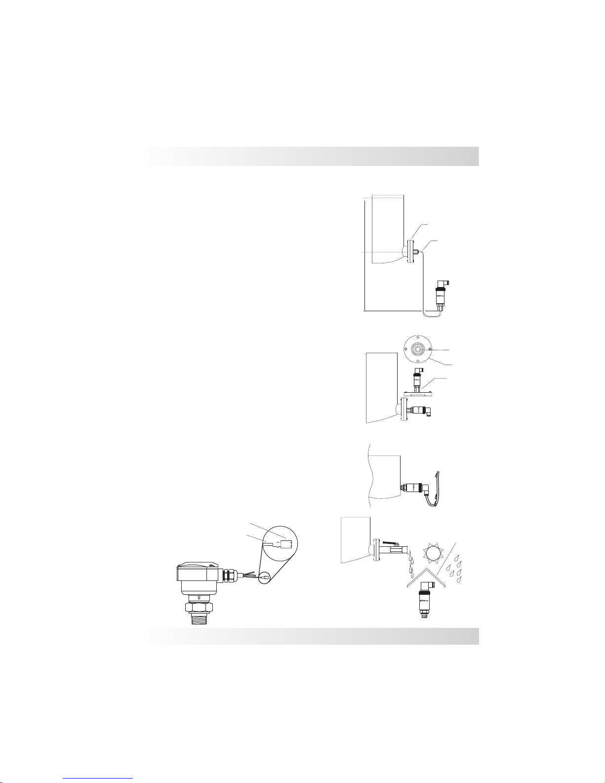
In situations where the tank is suspended, the
transmitter should always be installed in a point
below the connection using the sealing system
with capillary connection. This type of installation
is required when you want to mount the
transmitter in a better position for viewing (Fig. 3) .
Note: Evaluate what type of product is to be
measured. Aggressive products can damage the
membrane of the sensor element or of the o´ring
seal. That is why it is necessary to determine the
compatability of the product before the unit is
purchased and installed. (Fig. 4).
Install the transmitter so that the electrical cable
dips below the transmitter (or makes a "U") so that
water can drain off the cable without the risk of
infiltrating into the transmitter (Fig 5).
Use a cable with vent tube for all Sitron transmitter
models so that the linearity of the output signal and
the operation of the unit is not compromised (this
special cable can also be provided by Sitron) (Fig.
7).
Avoid installing the transmitter underneath a tank
or were splashing or overflow of the product might
damage the unit. If this is unavoidable, install a
barrier to protect the unit from the product
infiltrating from the outside of the transmitter.
This may also be recommended when the
installation is in an open environment. Weather
variations can create internal condensation, so it
is best to avoid exposing the transmitter to direct
Min.
Max.
height “h”
Sealing
Cappilary
Membrane
Seal
Flange
Fig. 4
Fig. 3
Fig. 5
Fig. 7
Filter
Vent tube
Fig. 6
Page 13
13
Calibration
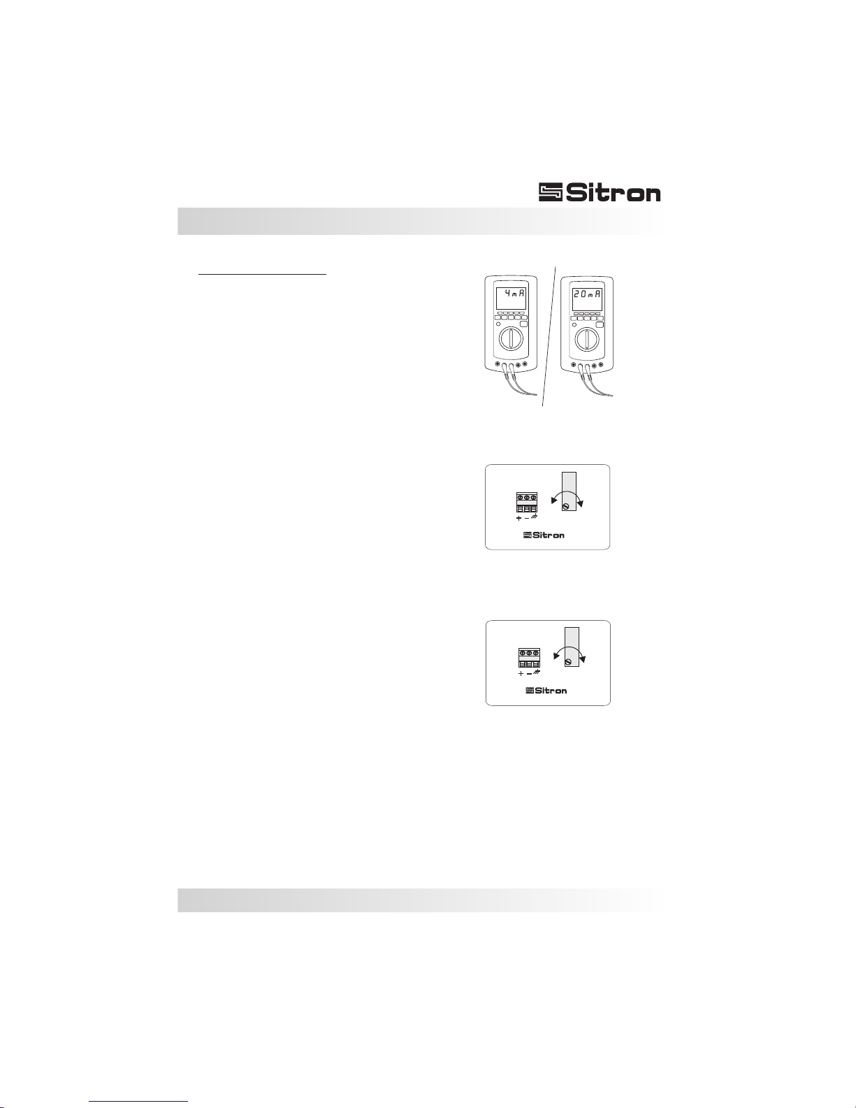
Z(zero)
S(span)
Fig.2
Fig.1
SP98FA and SP96FA
Before the calibration of the unit is first tested,
the process should be free of pressure or (if
that is not possible) the unit should first be
tested outside of the vessel.
Make sure the muliti-meter is correctly
connected in series with the source and the
instrument. The scale should be set to mA
First confirm that the current output is at 4mA
(for SPFA units you can adjust the trimpot
"zero".) Turning the trimpot clockwise
increases the current value, and turning it
counterclockwise decreases the value
(Fig.2).
After adjusting (if necessary) the 4mA (zero)
install the unit in the process or fill the vessel
to increase the pressure of the process to the
maximum level desired. If necessary, turn the
trimpot (Span) to adjust the 20mA signal
(Fig. 3).
After calibrating the unit for the first time, it is
recommended that the you re-check the zero
and span ouput with your multimeter. This will
confirm that the unit is properly calibrated or if
further adjustment is necessary.
Page 14
14
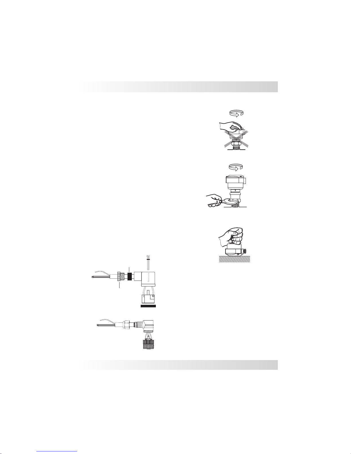
Seal the thread with Teflon tape before
installation.
(Fig. 1).
When tightening the sensor, use only use the
316S.S. hexagon fitting to achieve a seal, do not
twist with the body of the sensor.
The transmitter should not be dropped or suffer
any impact or fall, as this can damage the
electronics or the sensor (Fig.3).
Electrical connection with DIN connector:
Figure 4. Shows the steps for proper assembly of
the connector. When you tighten the threaded
part, stop once you feel that the rubber seal is at its
maximum compression point. Do not over-tighten
the thread. It is very important that the connector is
securely sealed so that the class protection is
maintained and no infiltration occurs.
Do not turn or handle by the housing
(Fig. 2).
Do not insert any object into the entry point of the
transmitter supply. This will immediately damage
the membrane.
Fig. 1
Fig. 2
Fig. 3
Handling
Rubber seal connection
Screw
Screw O’ring
Cable seal
Cable gland
Enclosure
Fig.4
Cable
Cable
Vent tube
Vent tube
Page 15
15
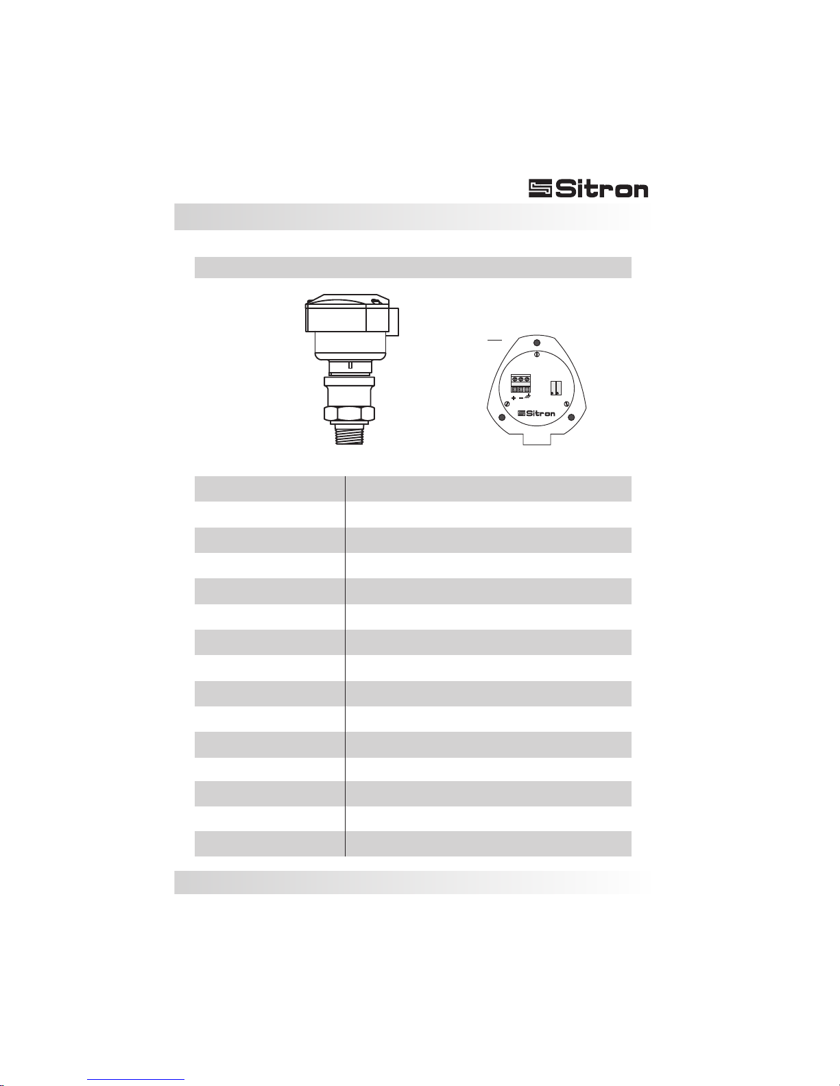
Ceramic capacitive
Cable gland ½”NPT
4...20mA (2 wires )
-1 to 40 Bar
IP 65
22mA max.
316 SS
-10 to +80ºC
12...30Vdc
3 x F.S.
+/- 0.5%
SP98FA
Z
S
Fiberglass Nylon
Zero & Span
N1
BSP or NPT - flange or sanitary
Technical Specifications
Housing
Adjustment
Application
Power supply
Consumption
Output
Accuracy
Sensor type
Range
Electrical connection
Process connection
Body material
Work temperature
Over pressure
Class protection
Pressure and Level measurement for liquids and gas
Page 16
16
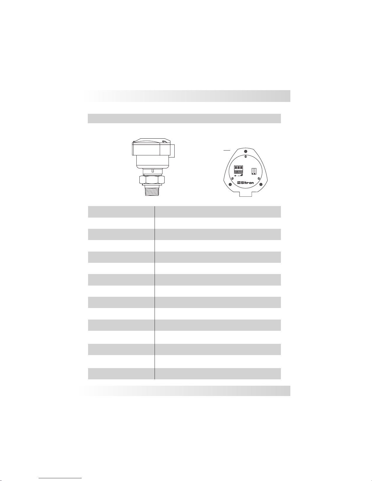
Technical Specifications
316 SS piezoresisitve silicon
4...20mA (2 wires )
-1 to 200 Bar
IP 65
22mA max.
316 SS
-10 to +80ºC
12...30Vdc
3 x F.S.
+/- 0.5%
SP96FA
Z
S
Housing
Fiberglass Nylon
Adjustment
Zero & Span
N1
Cable gland ½”NPT
BSP or NPT - flange or sanitary
Application
Power supply
Consumption
Output
Accuracy
Sensor type
Range
Electrical connection
Process connection
Body material
Work temperature
Over pressure
Class protection
Pressure and Level measurement for liquids and gas
Page 17
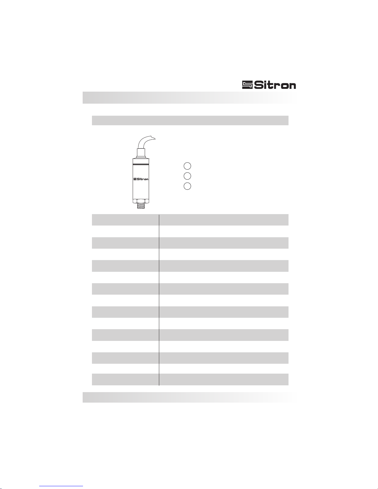
17
316 SS silicon piezoresistive
Polyethylene
4...20mA (2 wires )/ ,1...5V, 0...5V (3 wires)
0.1 to 1000 Bar
IP 68
22mA max.
304 SS
-10° to + 80°C
12...30Vdc
3 x F.S.
+/- 0.5%
SP68
M20*1.5” / 1/2”(BSP or NPT) (others)
Reverse polarity
3
2
1
Red (+)
Black (-)
Yellow (Out) 3 wires
Technical Specifications
Application
Power supply
Consumption
Protection
Output
Accuracy
Sensor type
Range
Electrical connection
Process connection
Body material
Work temperature
Over pressure
Class protection
Pressure and Level measurement for liquids and gas
Page 18
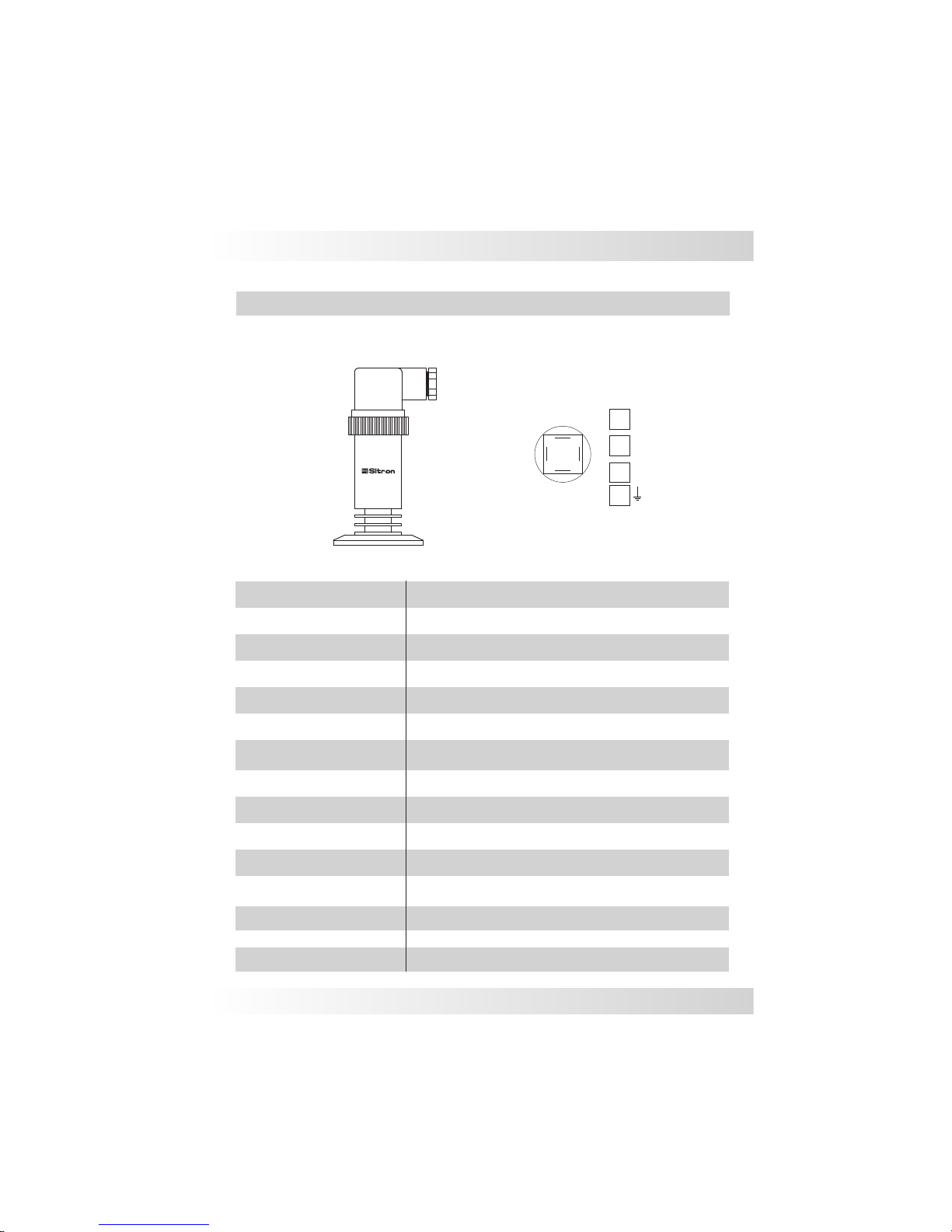
18
316 SS piezoresistive
Silicon or olive oil
DIN43650 or M12 connector
4...20mA (2 wires ) 0...4,5V (3 wires) upon request
0,1 to 1000 Bar
IP 65
22mA max.
304 SS
12...30Vdc
3 x F.S.
+/- 0,5%
SP30
M20*1.5 , 1/2” BSP or 2”TC
0 to +80ºC ( olive oil sensor)
-10° a + 80°C ( silicon sensor)
(-) Negativo
(+) Positivo
Out (V)
2
3
1
DIN 43650 Connector
1
3
4
2
( ) GND
4
Reversal polarity
Technical Specifications
Application
Power supply
Electrical connection
Process connection
Work temperature
Body material
Consumption
Sensor type
Protection
Accuracy
Range
Output
Class protection
Over pressure
Pressure and Level measurement for liquids and gas
Page 19
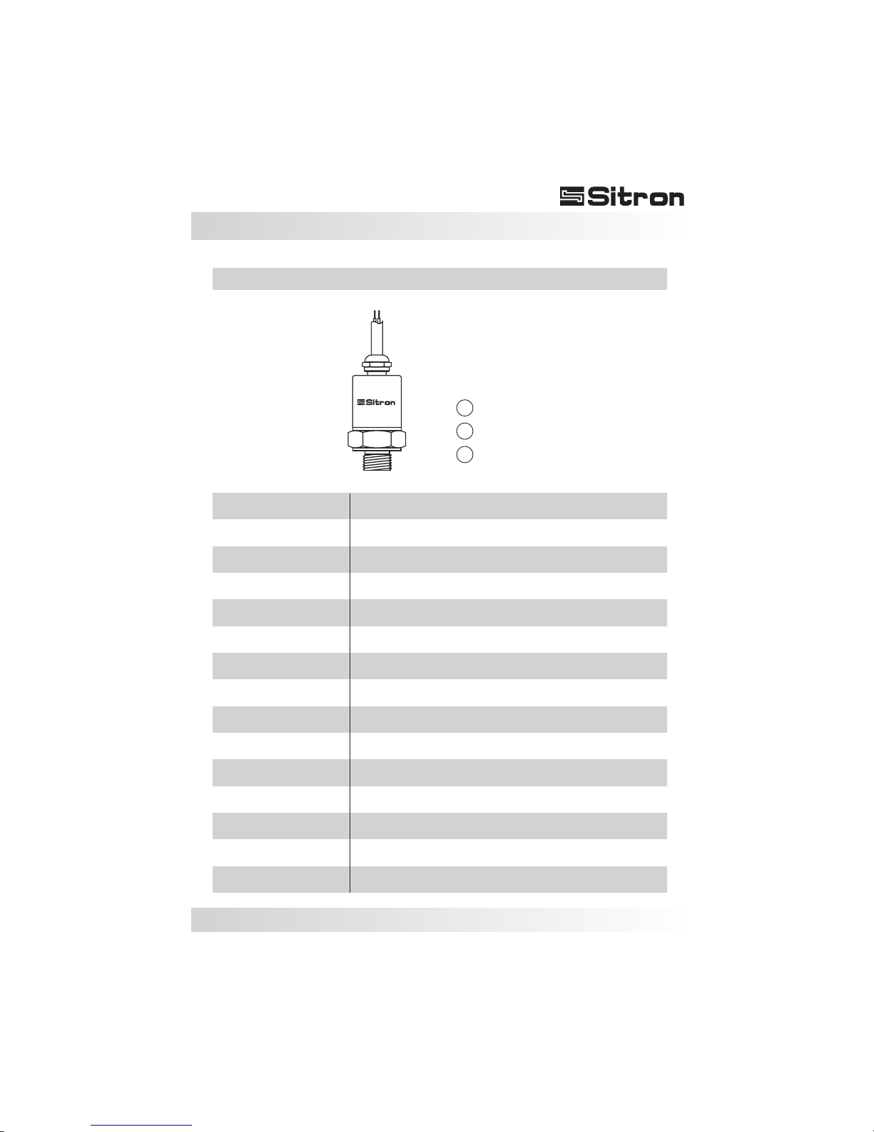
19
316 SS silicon piezoresistive
Cable or M12 connector
4...20mA (2 wires ) 0...5 e 1...5V (3 wires)
0,2 to 250 Bar
IP 65
22mA max.
304 SS
-10 to +80ºC
12...30Vdc
3 x F.S.
+/- 0.5%
SP10
G1/4” / 1/4"-18 NPT / 1/8"-27 NPT / M14*1.5 /
M12*1.5 / 1/4"-19 PT / 7/16"-20 UNF (female)
3
2
1
Red (+)
Green (-)
Yellow (Out) 3 wires
Reversal polarity
Technical Specifications
Application
Power supply
Electrical connection
Process connection
Work temperature
Body material
Consumption
Sensor type
Protection
Accuracy
Range
Output
Class protection
Over pressure
Pressure and Level measurement for liquids and gas
Page 20
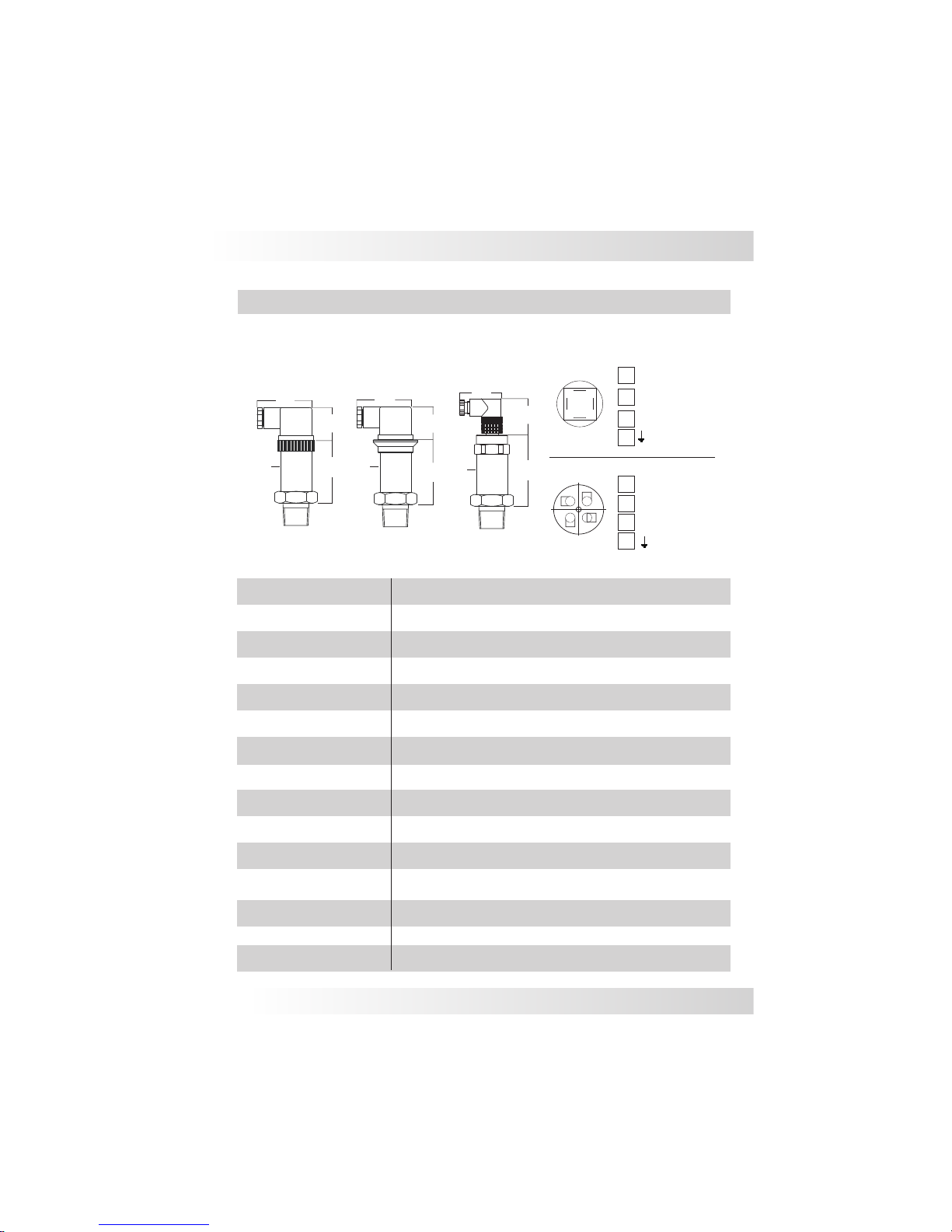
Accuracy
Range
Sensor type
Power supply
Application
Consumption
Output
Protection
4...20mA (2 wires ) 0,5...4,5/ 1...5V/ 0...5V (3 wires) upon request
Process connection
Electrical connection
BSP ou NPT - flange or sanitary
Work temperature
Class protection
Body material
Over pressure
SP21
316 SS silicon piezoresistive
DIN43650 or M12 connector
0.1 to 1000 Bar
22mA max.
12...30Vdc
2
Reverse polarity
+/- 0.25%
1
3
M12 connector
304 SS
-10° to + 80°C
DIN 43650 connector
2
Technical Specifications
IP 65 / IP66 / IP67
3 x F.S.
3
4
3
4
2
1
3
4
4
2
1
1
Out (V)
(-) Negative
(+) Positive
Out (V)
( ) GND
( ) GND
20
(-) Negative
(+) Positive
30mm
Ø
47mm
30mm
Ø
28mm
56mm
28mm
56mm
47mm
SP21
SP21- IP66
30mm
Ø
65mm
35mm
36mm
SP21- IP67
Hex. 1.1/16”
Pressure and Level measurement for liquids and gas
Page 21
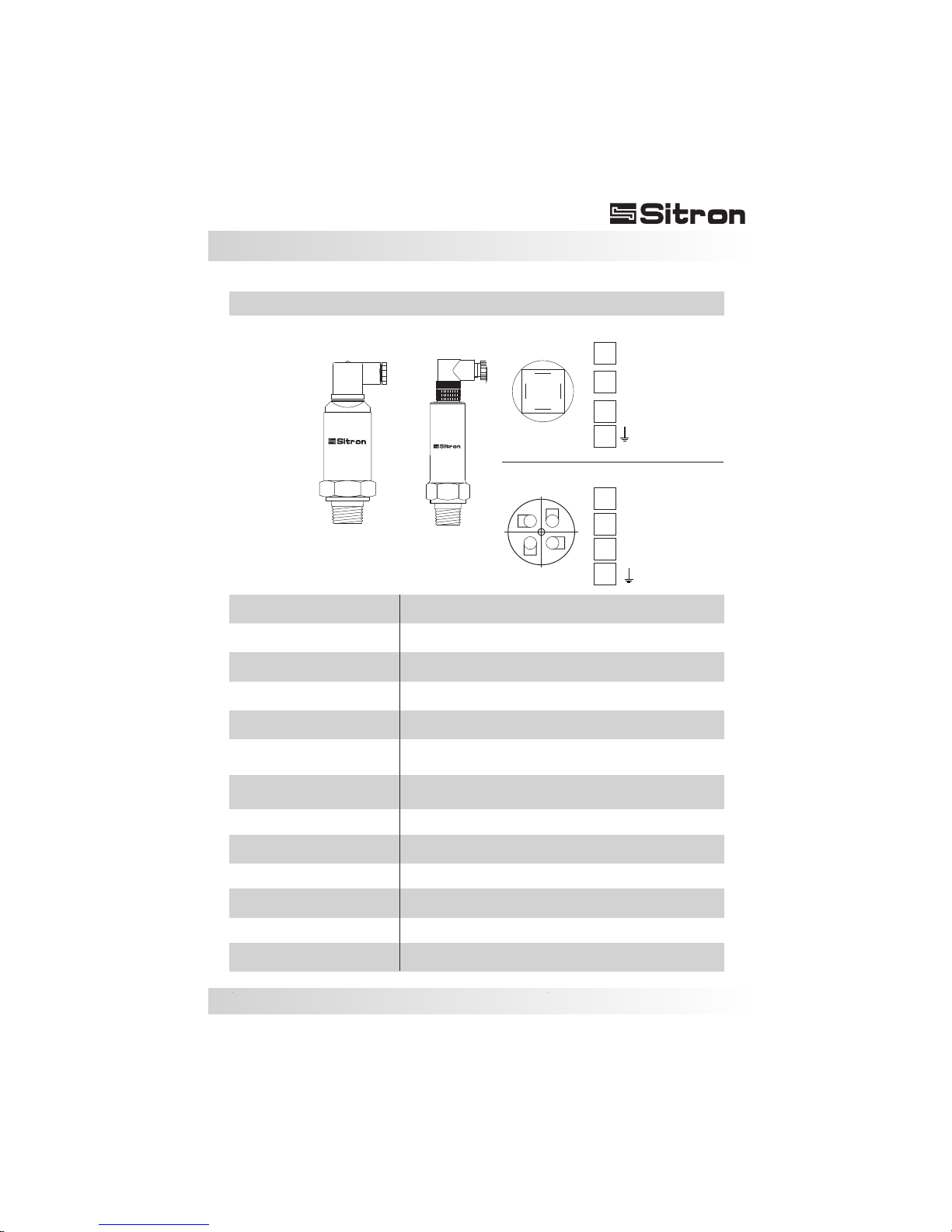
21
Technical Specifications
(-) Negative
SP-98 Ceramic capacitive
SP-96 316 SS silicon piezoresistive.
(+) Positive
Out (V)
DIN43650 or M12 connector
4...20mA (2 wires) or 1...5 (optional)
SP-98 (-1 to 40 Bar)
SP-96 (-1 to 200 Bar)
IP 65
BSP or NPT, flange or sanitary
22mA max.
316 SS
-10 to +80ºC
12...30Vdc
3 x F.S.
+/- 0.5%
SP98 / SP96
2
3
1
DIN 43650 connector
1
3
4
2
Work temperature
Process connection
Accuracy
Range
Class protection
Body material
Electrical connection
Sensor type
Over pressure
Power supply
Application
Consumption
Output
4
1
2
3
2
1
M12 connector
(-) Negative
(+) Positive
Out (V)
3
( ) GND
4
( ) GND
4
Pressure and Level measurement for liquids and gas
Page 22
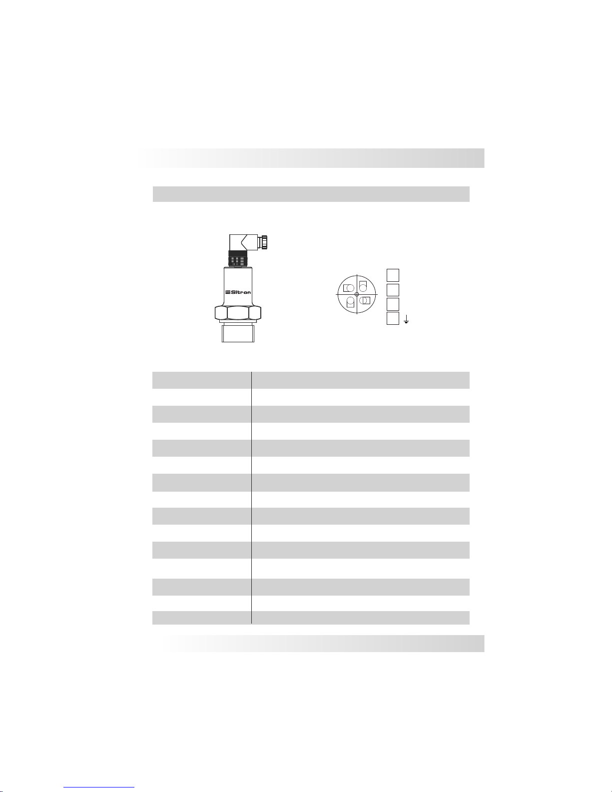
Accuracy
Range
Sensor Type
Power supply
Application
Consumption
Output
Protection
Pressure and Level measurement for liquids and gas
4...20mA (2 wires )
Process connection
Electrical connection
BSP, NPT, flange or sanitary
Work temperature
Class protection
Body material
Over pressure
SP81
Piezoresistive ceramic
M12 connector
0...600 Bar
22mA max.
12...30Vdc
2
Reverse polarity / Electromagnetic Interference
+/- 0.25%
1
3
M12 connector
316 SS
-10° to + 80°C
Technical Specifications
IP 67
3 x F.S.
4
2
1
3
4
(-) Negative
(+) Positive
( ) GND
22
Page 23

23
Trouble Shooting
Lack of
Linearity
Deformed membrane
Incorrect power supply
Call for service
Check the installation,
may need to install
a stilling well
Output Signal
Fixed
Problem with the electronics
No Output Signal
Confirm that the unit was
installed in accordance with the
recommendations
Output Signal
Oscilating
Check the power supply
Temperature outside
the operating range
Process temperature
must be within stated range
Turbulence in the process
Deformed membrane
Infiltration
Call for service
Fail
Cause
Solution
Page 24
24
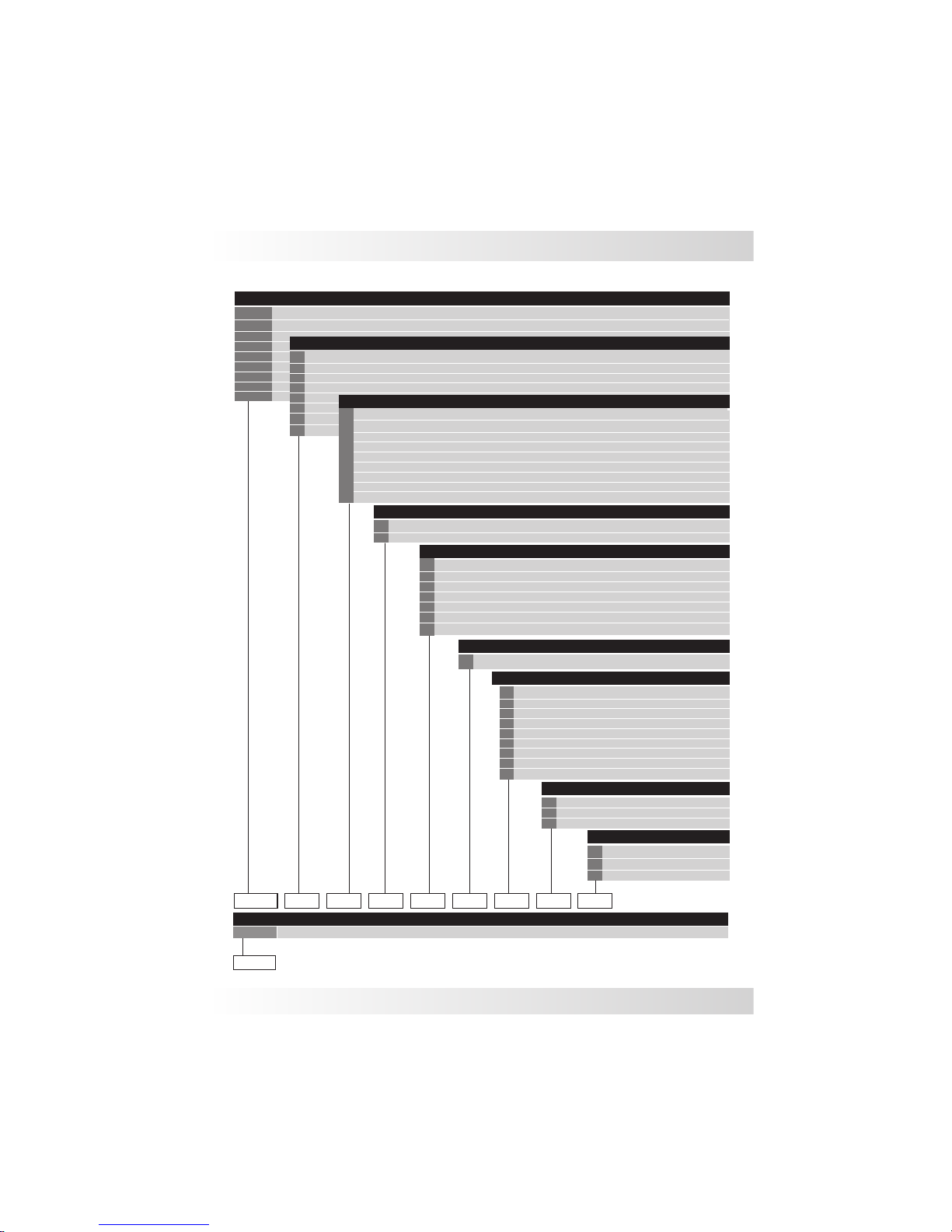
Ordering Information
Polypropylene Body and connection
Digital indicator
PVC body and connection
ACCESSORIES
None
PVC Body Ceramic sensor
Cable
316 SS Differencial silicon
316 SS Silicon (Absolute)
316 SS Gauge silicon
316 SS Gauge Olive oil
X
I
0
None
Flush mounted membrane
316 SS (Olive oil)
OPTION
SENSOR TYPE
Cable length (especify)
Ceramic
PE
P
F
Others
M16 metal w/ 2m Cable
Especify
CP
Small Nylon
0
A
B
C
D
G
H
X
DIN Connector 43650
ELECTRICAL CONNECTION
RANGE
M12 Connector
PC 1/2" BSP
PC 1/2” NPT
1/2" BSP
R
FLANGE ANSI 150# 316 SS
FLANGE ANSI 150# 346 SS
FLANGE ANSI 150# PVC
None
PROCESS CONNECTION
1
2
7
D
Y
M
L
DIN - Female 316 SS
HOUSING
SMS Female
SMS Macho
TRI-CLAMP
Hart Talker - USB / Hart Interface
SC
N1
DIMENSION
BSP
NPT
K
R
B
E
F
N
S
T
Y
1 1/2”
1/4”
3/8”
1/2”
3/4”
1”
3”
2”
3
2
4
5
6
7
1
9
9
COMMUNICATION
MODELS
SP96FA
SP98FA
SP96
SP98
SP21
SP68
SP30
SP10
HT
SP81
Page 25

Terms & Conditions
25
Sitron's TERMS & CONDITIONS
Design: Sitron reserves the right to make any alterations or changes necessary to
improve the Products, correct defects or to make the Products safer, without prior notice
or consent by Buyer.
Pricing: All stipulated amounts shall be in US dollars and all prices quoted are valid for
thirty (30) days from date of offer, unless otherwise stated.
Safety and Instructions: The Buyer ensures that it and all its representatives and agents
will observe all safety and technical instructions in Sitron's operating manuals, catalogs
or other directions or instructions (either written or verbal).
Delivery and Freight: All goods are sold FOB point of shipment, Brasil. Transportation
to the destination is the Buyer's responsibility and Buyer alone shall bear the cost of
freight, optional or other shipping requirements, and or insurance. Sitron shall not be
liable for loss or damage to the Products after said Products are delivered to or received
by the shipper/carrier, and all risk of damage or loss shall immediately pass to Buyer.
Receiving, unloading and storing of Products will be the responsibility of the Buyer.
Buyer also accepts that courier may choose to return Products to Sitron if any local taxes
or duties are not paid by Buyer at point of delivery. Buyer must make any and all claims
for corrections or deductions within ten days of the delivery of the Products.
Shipment Delays: Sitron has no control over the length of time shipments may be held
at customs, etc. For this reason, Sitron commits only to a "shipment date", not a "delivery
date". Buyer shall not hold Sitron liable for claims resulting from delay in shipment
except in cases where these terms are accepted in writing by Sitron. Acceptance of
delivery of Products by Buyer shall constitute a waiver of all claims for delay.
Partial Deliveries: While Sitron strives to deliver all orders on time and complete, Sitron
reserves the right to make partial deliveries when necessary.
Changes: Any changes initiated by the Buyer which affects the products specifications;
quantities ordered; delivery schedule; method of shipment or packing; or delivery
location, must be made in writing and signed by both parties.
In this case, Sitron reserves the right to adjust the pricing and or delivery of the order,
which will be agreed to by both parties before further work is performed on the order.
Any such requests will be priced according to the scope of changes and the status of the
current order. Customer must sign and return or acknowledge approval of drawings
along with any Purchase Order. If approval drawings are not returned with order, the
delivery date may be held or pushed back until Customer has acknowledged approval.
Cancellation: Any cancellation of the Contract by the Buyer shall be effective only if
made in writing and accepted, in writing by the Sitron. In such a case, Sitron is entitled to
reasonable cancellation charges including but not limited to labor, material and other
related expenses.
Page 26

26
Warranty
Termination Fee Schedule:
Order entered but not released for manufacturing 10%
Order in any stage of production 75%
Order complete and ready for shipment 100%
Warranty: Sitron warrants its product against manufacturing defects in material and
workmanship, when installed in applications approved by Sitron, for a period of one
year from the date of original shipment, unless otherwise stated in writing by Sitron.
Sitron is not responsible for damage to Sitron's Products or other equipment or products
because of improper installation or misapplication of the Products by Buyer. Installation
or startup of Sitron's equipment must be performed under the guidelines set forth in
Sitron's instruction manuals, wiring diagrams, etc., or performed under the direct
supervision of Sitron's field technicians or Sitron's authorized Sales Representatives, in
order to be covered by Sitron's warranty.
Sitron shall be under no liability in respect to any defect from fair wear and tear, willful
damage, negligence, abnormal working conditions, failure to follow Sitron's instructions
(whether written or verbal), misuse, modification or alteration or attempted repair of the
Goods without Sitron's approval.
Sitron shall not be liable under the above warranty (or any other warranty, condition or
guarantee) if the total price for the Products or the payment of Services rendered has
not been paid by the due date for payment.
The Buyer must make all tools, resources or personnel available to help Sitron to
diagnose the defect without any back charge. In absence of Buyer's cooperation in this
regard, there shall be no liability under the above Warranty.
Sitron's liability under this warranty shall be limited to repair or replacement at Sitron's
option of such defective Products, FOB factory, upon proof of defect satisfactory to
Sitron. Warranty does not include transport.
Return Goods: No goods may be returned without Sitron's permission and an RMA
number. Sitron assumes no responsibility for return shipments made without
permission. In issuing credit for such shipments, Sitron reserves the right to charge a
restocking fee dependent on Sitron's ability to recondition and resell the returned
equipment.
Insurance: The responsibility for insuring the Goods after the risk in them has passed to
the Buyer shall be that of the Buyer.
Confidential Information: All drawings, specifications, and technical information
provided by either Buyer or Sitron shall be treated as confidential and shall not be
disclosed to anyone other than those who require it as part of the fulfillment of the order.
Buyer agrees that the designs and/or any other related material provided are and
remain Sitron's exclusive property and that the Buyer acquires no right, title or interest
to this intellectual property, whether in whole or in part.
Errors: Sitron reserves the right to correct all typographical or clerical errors or
omissions, in its prices or specifications.
Page 27

Sitron - Brasil
R. Baronesa de Itu, 83
São Paulo - SP - 01231-001
T.: (5511) 3825-2111
F.: (5511) 3825-2171
www.sitron.com
BRASIL: [email protected]
USA / Other Countries: [email protected]
Sitron - USA
1800 Prime Place
Hauppauge, NY 11788
PH: 516-935-8001
FX: 800-516-1656
SP_01_2016
 Loading...