

Sitron CF12 DC,CF12 AC User Manual
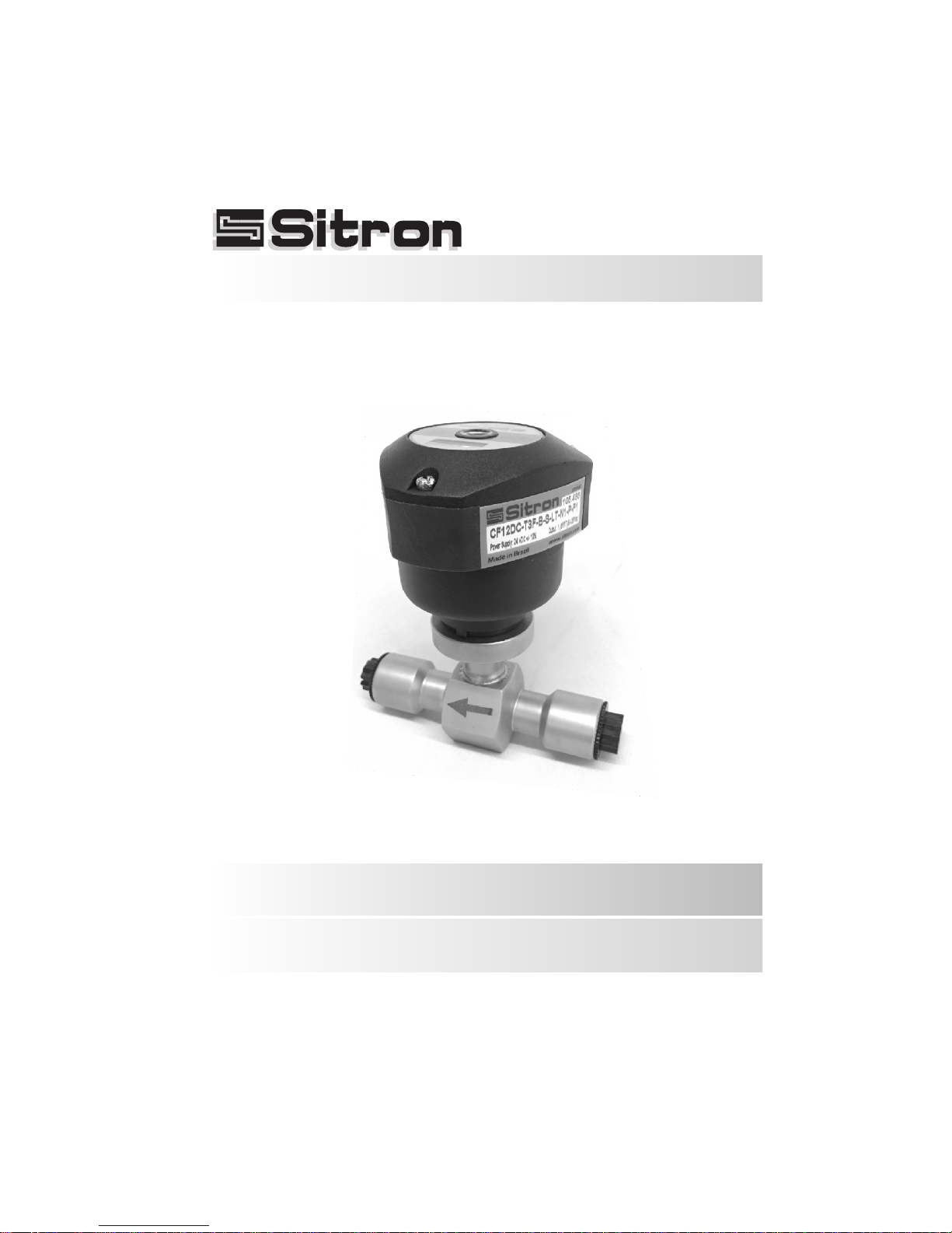
CF12 AC / CF12 DC
Thermal dispersion
Flow switch for Low Flow
USER’S GUIDE
Installation, Operation

03
Contents
Introduction . . . . . . . . . . . . . . . . . . . . . . . . . . . . . . . . . . . . . . . . . . . . . . . . . 4
Models & Dimensions . . . . . . . . . . . . . . . . . . . . . . . . . . . . . . . . . . . . . . . . . 5
Wiring Diagram . . . . . . . . . . . . . . . . . . . . . . . . . . . . . . . . . . . . . . . . . . . . . . 6
CF12 Relay Status Guide . . . . . . . . . . . . . . . . . . . . . . . . . . . . . . . . . . . . . . 8
Installation . . . . . . . . . . . . . . . . . . . . . . . . . . . . . . . . . . . . . . . . . . . . . . . . . . 9
Calibration . . . . . . . . . . . . . . . . . . . . . . . . . . . . . . . . . . . . . . . . . . . . . . . . . 10
Technical Specifications . . . . . . . . . . . . . . . . . . . . . . . . . . . . . . . . . . . . . . 11
Ordering Information . . . . . . . . . . . . . . . . . . . . . . . . . . . . . . . . . . . . . . . . . 12
Trouble Shooting . . . . . . . . . . . . . . . . . . . . . . . . . . . . . . . . . . . . . . . . . . . . 13
Terms & Conditions . . . . . . . . . . . . . . . . . . . . . . . . . . . . . . . . . . . . . . . . . 14
04
Introduction
The CF12 series of thermal flow switches is designed to monitor flow status of
liquids and gases and can also be used to detect level.
A chain of 8 LED's gives the user a visual indication of the flow status of the
switch.
There are two red LEDs that indicate whether or not the unit has detected flow,
a yellow LED to indicate the set point (for increasing or decreasing flows) and 5
green LEDs that indicate the amount of flow beyond the set point of the unit.
The CF12 also includes a di-chromatic (red/green) LED which shows the
switch point status of the unit.
The sensing element and connection of the CF12 are made with 316L S.S. and
can be coated when necessary .
The enclosure is offered in either glass filled nylon or aluminum. All models
can be ordered with a great variety of threaded, flange, or sanitary process
connections.
With the addition of a built in “T-Reducer” connection, the CF12 is now able to
detect flow rates between 3ml and 300ml per minute.
Characteristics
Simple to install.
Excellent low flow sensitivity.
No moving parts-maintenance free reliabity.
Maximum working pressure of 1450 PSI (100 bar).
Fast response time for flow or level (Adjustable from 1-10 seconds).
Thermal dispersion
Flow switch for Low Flow
05
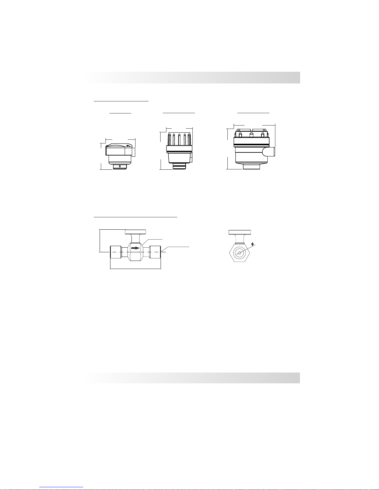
Models & Dimensions
Mounting Options
126mm
130mm
130mm
89mm
76mm
89mm
Nylon-N1
Aluminum-G1
Aluminum-G2
Body Dimension (standard)
6
Hex. 1 1/2"
BSP/ NPT female
49
110
More connections upon request
06
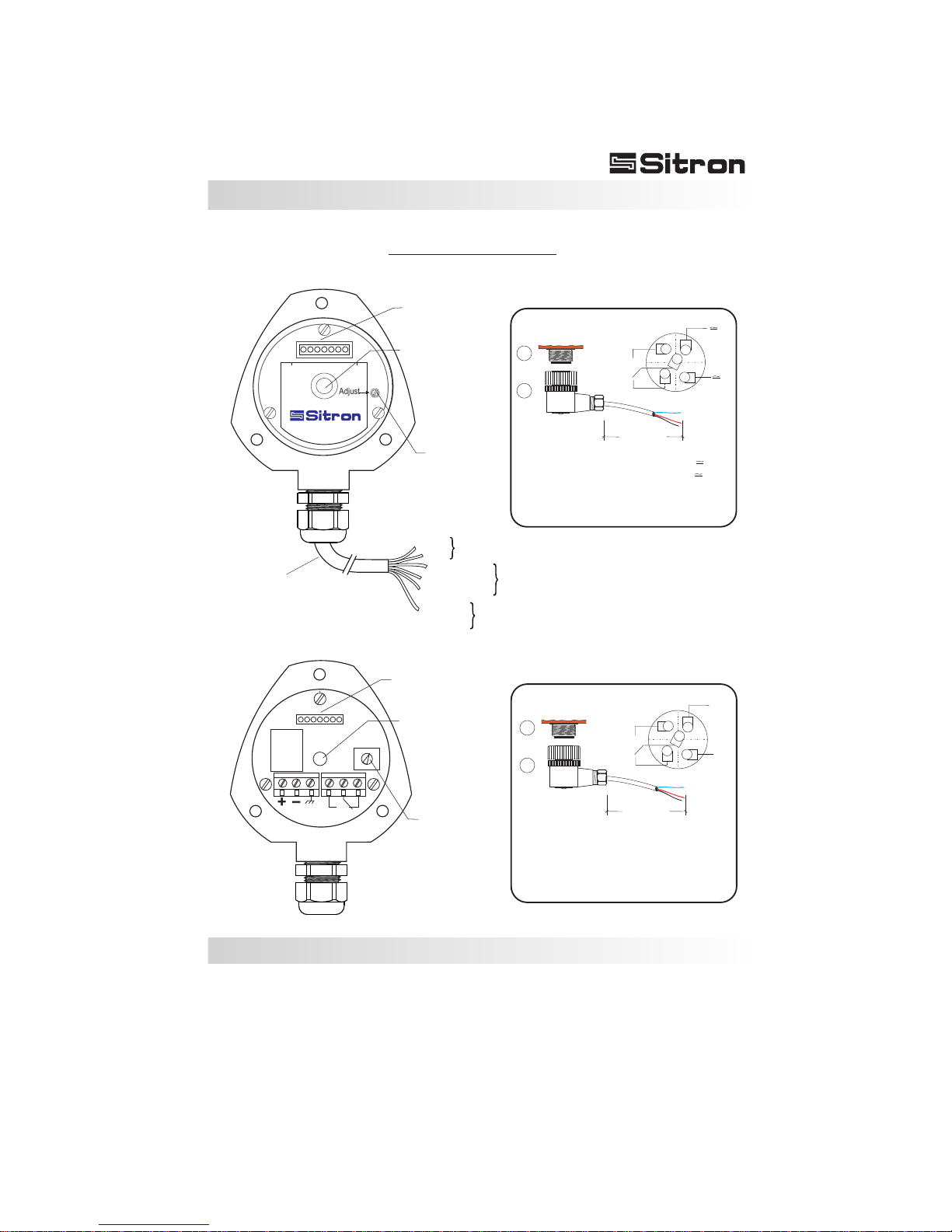
Electrical Connections
Standard Connection w/
2 meters of Cable
+
_
Bargraph (B1)
Bargraph (B1)
Adjust (P1)
Adjust (P1)
Central LED Status (L1)
(Red/Green)
Central LED Status (L1)
(Red/Green)
Adjust
CF 12 DC
Adjust
Red
White (NC)
Green and
Yellow
or solid Yellow
Blue (common)
Green (NO)
Black
Power
Supply
Contacts
Ground
CF 12 AC
2000mm
1
2
Connector
12mm
NO or NC
contact
2000mm
1
2
Connector
12mm
+
++
_
__
NO or NC
contact
Nylon Enclosure (N1)
M12 Connector Optional
M12 Connector Optional
1 - Power Supply (+)
2 - Power Supply (-)
3 - Ground
4 - NO Contact
5 - Common
6 - NC Contact
1 - Power Supply
2 - Power Supply
3 - NO Contact
4 - NC Contact
5 - Common
1 - Power Supply (+)
2 - Power Supply (-)
3 - NO Contact
4 - NC Contact
5 - Common
1
1
5
5
2
2
3
3
4
4
 Loading...