

Page 1
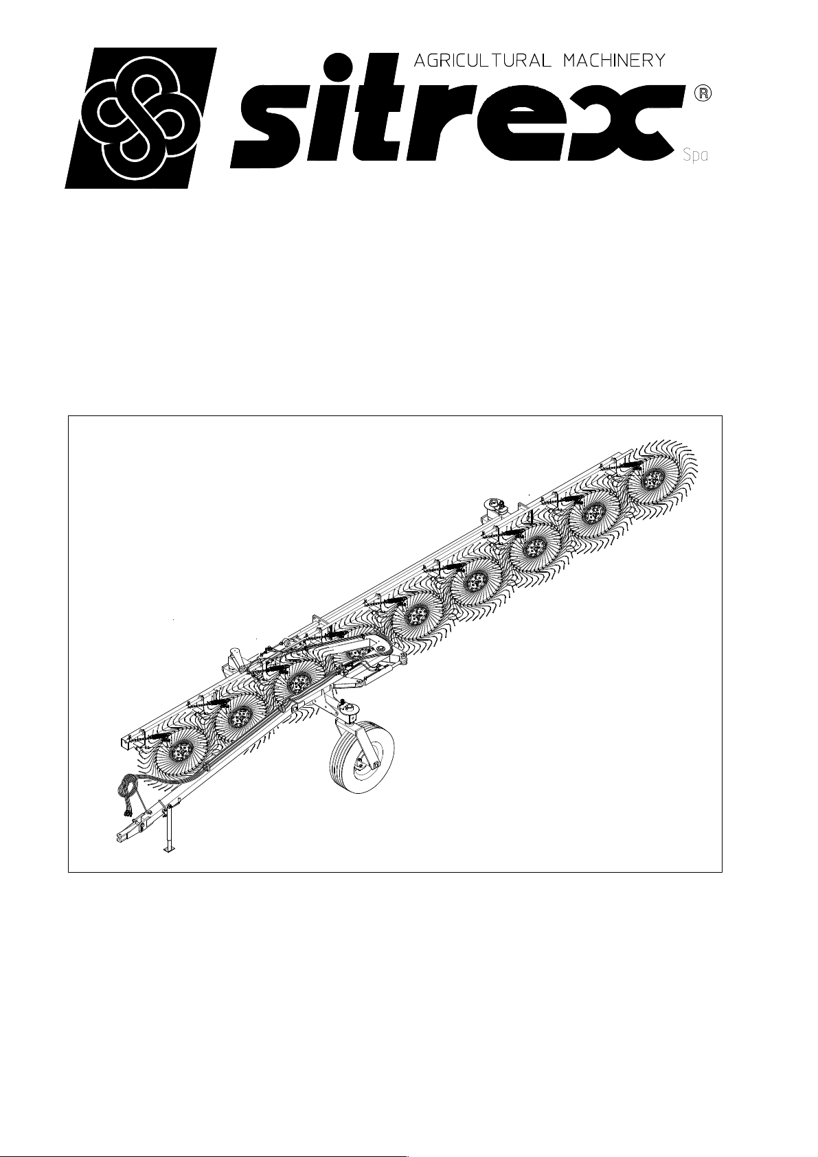
ASSEMBLY
USE AND MAINTENANCE
TR/6-7-8-9 S
10-2014 FROM SERIAL NO. 255390
Page 2

WARRANTY
When the machine is received, regardless of how it is delivered (in a crate,
partially assembled, assembled, etc.), the customer must check to make sure that
it is in good condition and that all components are present. To report any
damage, any missing parts or anything else that compromises the perfect
condition of the machine, submit a written claim to the sales agent and/or the
distributor and/or the manufacturer within eight days from the delivery date.
The warranty will not be recognized for problems that undoubtedly result from
unpacking, assembly or usage operations that do not comply with the provisions of
this manual.
The warranty will not be recognized if the customer is not able to return the defective
part (or parts) to the manufacturer, who therefore will not recognize any repair and/or
replacement costs, unless written agreements have been made between the customer
and the manufacturer or other persons authorized by the manufacturer. If there are
defective parts acknowledged preventively but not definitively by the manufacturer,
the buyer must return them (shipping costs covered) to the manufacturer who, after
verifying that they actually are defective, will repair or replace them and send them
back to the customer. If the manufacturer finds that the parts are not defective, the
customer will not be covered by the warranty.
The warranty is null and void if it is clear that the machine has been used improperly
and/or repaired without authorization.
The manufacturer shall not recognize any warranty in the case that its workers,
employees, agents, dealers or any others not specifically authorized by the
manufacturer should make agreements with the customer that do not fall within the
aforesaid conditions.
The warranty will be valid for a period of 12 (twelve) months starting from the date
of delivery to the original purchaser. This warranty substitutes any other warranty
expressed or implied by anyone, as well as any other obligation of the manufacturer.
NB: As specified, actions to be considered for replacement and repair under warranty
must first be approved by the manufacturer. The customer will not be reimbursed for
costs resulting from repairs and/or replacements made without the previous
authorization of the manufacturer. Before making repairs notify the manufacturer in
detail, so that it may evaluate whether to authorize the repair or to replace the part.
CHAPTER
1) GUIDE TO THE MEANING OF SIGNS AND SYMBOLS
2) Summary of safety and accident prevention regulations
3) PRODUCT IDENTIFICATION ANDTECHNICAL SPECIFICATIONS
4) DELIVERY OF THE MACHINE AND ASSEMBLY
5) MAINTENANCE POINTS AND INSTRUCTIONS
6) ADJUSTMENT, PREPARATION AND USE
2
Page 3
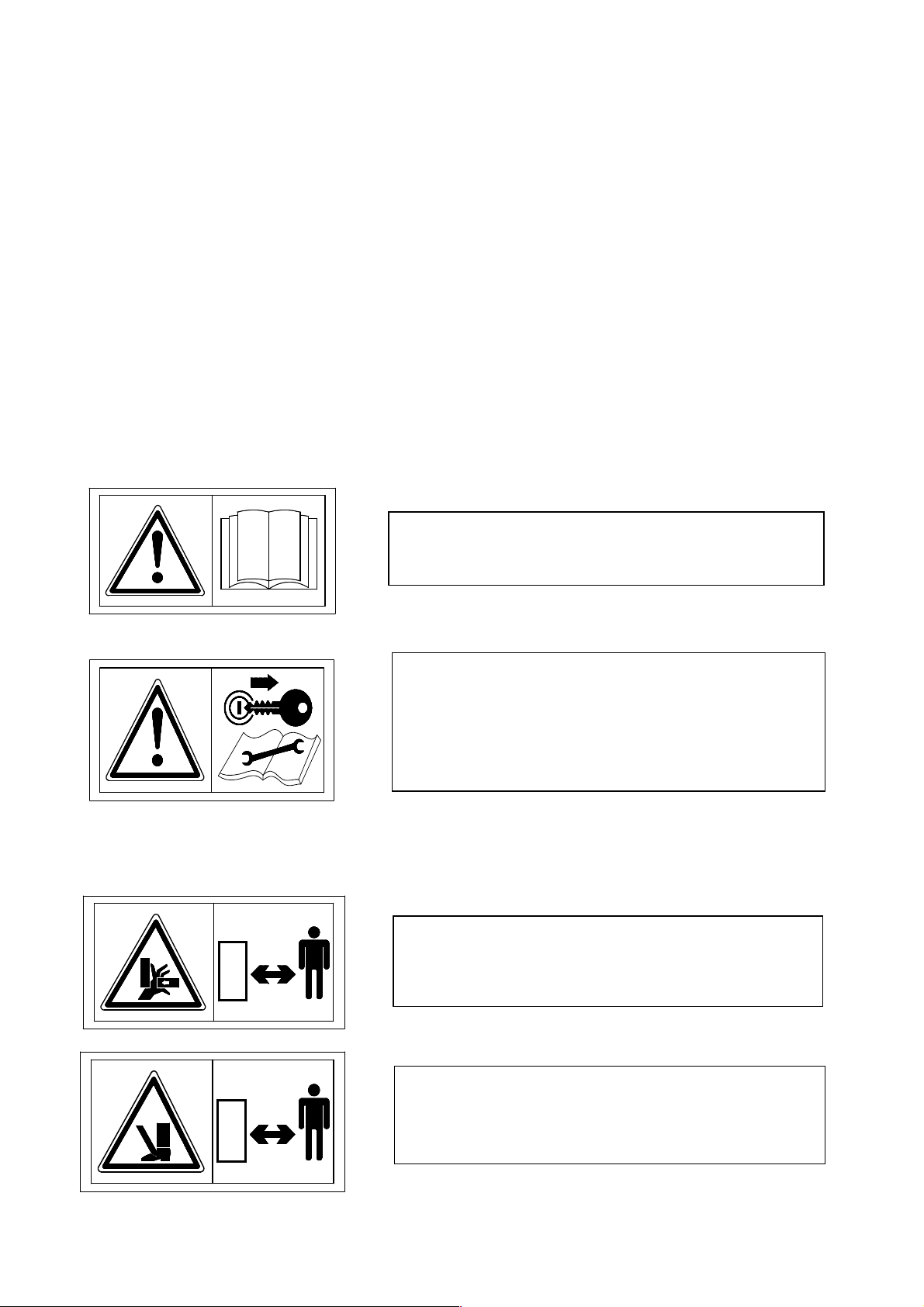
1) MEANING OF THE SIGNS AND SYMBOLS APPLIED
TO THE MACHINE AND/OR USED IN THIS MANUAL.
IMPORTANT
These signs and symbols give the operators information on how to make the best use
of the machine so as to prolong its life, avoid damage to the machine and to objects,
optimize work and, above all, on how to avoid injury to the operator and to
anyone who is within the operating range of the machine. Note: most of the signs
and symbols you will find here below are applied to the machine, but some may be
only in this manual, and they are there to indicate how to act or what must be done
during assembly, use, maintenance and/or repairs.
WARNING SIGNS AND SYMBOLS
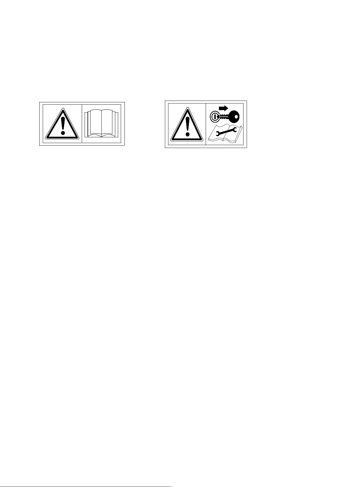
1) Read the instruction manual before
starting any operations.
2) Before doing any checking, maintenance
and/or repair operations, stop in a suitable
place, turn off the tractor, apply the brake,
remove the ignition key and consult this
manual.
DANGER SIGNS AND SYMBOLS
3
3) Warns against the potential and serious
danger of crushing hands. Keep your distance.
4) Warns against the potential and serious
danger of injury to the feet. Keep your
distance.
Page 4
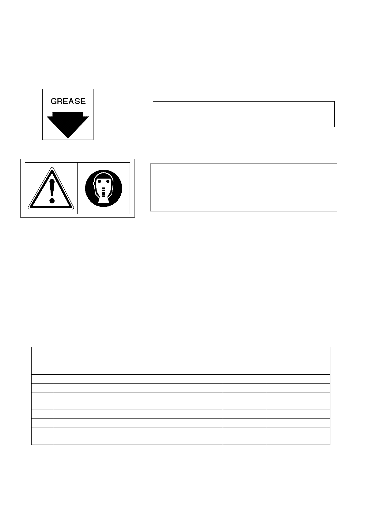
SIGNS AND SYMBOLS OF INDICATIONS AND
RULES
5) Indicates the points to be greased
6) Recommends that suitable protective equipment
and clothing be worn to prevent injury during the
stages of assembly, use, maintenance and/or
repairs.
Note: For the location of the signs and symbols on the machine, see p.5
1) LOCATION OF DECAL AND DEVICES FOR SAFETY, FOR THE
CONTROLS AND FOR IDENTIFICATION OF THE MACHINE AND THE
MANUFACTURER.
Pos.
DESCRIPTION
MACHINE & MANUFACTURER IDENTIF. PLATE
1
DECAL " FIRST OF ALL READ THE MANUAL"
2
DECAL " READ THE MANUAL BEFORE OPERATING"
3
SITREX LOGO DECAL (SMALL)
4
SITREX LOGO DECAL
5
MACHINE NAME DECAL
6
DECAL “DANGER OF INJURY TO HANDS” (SMALL)
7
GREASE POINTS DECAL
8
DECAL “DANGER OF INJURY TO HANDS”
9
DECAL “DANGER OF INJURY TO FEET”
10
Qty. Notes
1 See on the machine
1 See p. 3 step 1
1 See p. 3 step 2
1 See on the machine
1 See on the machine
1 See on the machine
3 See p. 3 step 3
10-11-12-13
3 See p. 3 step 3
2 See p. 3 step 4
See p. 4 step 5
4
Page 5
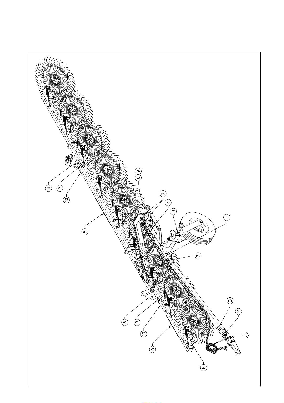
1) LOCATION OF DECAL AND DEVICES FOR SAFETY, FOR THE
CONTROLS AND FOR IDENTIFICATION OF THE MACHINE AND THE
MANUFACTURER.
5
Page 6

2) GENERAL SUMMARY OF SAFETY AND ACCIDENT
PREVENTION INSTRUCTIONS.
Read all the instructions and rules carefully before using the machine. If you
have any doubts, contact the dealer, the distributor or the manufacturer. The
manufacturer disclaims all liability for non-compliance with the safety and
accident prevention instructions and rules.
1) Pay attention to the danger signs and symbols on the machine and in the manual.
2) Do not touch moving parts.
3) All work on the machine (including adjustments) must always be done with the
tractor stopped, the brake on and the engine turned off.
4) It is strictly prohibited to carry persons and/or objects on the machine and/or on the
tractor.
5) It is strictly prohibited for persons without a license, without the necessary
experience or who are not physically fit to drive the tractor with the machine
connected.
6) All safety and accident prevention measures prescribed in this manual must be
strictly observed.
7) Always evaluate whether the tractor to be used is suitable for the purpose, given
that even if the machine is the trailed type, it alters the tractor’s stability; therefore,
take all the necessary precautions for working in safety (take into consideration the
type of terrain, tire pressure, etc.).
8) Check that all safety devices for transport and working are in good condition and
functioning before operating the machine.
9) When driving on public roads, always observe the traffic rules and regulations of
the country where you are working.
10) Familiarize yourself with all the controls and the use of the machine before
starting to work.
11) Wear suitable clothing while using the machine. Do not wear clothing that is
loose or that could get caught in the moving parts.
12) Never leave the driver’s seat while the tractor is moving.
13) Always bear in mind that the road holding, steering and braking of the tractor are
significantly affected by the machine being trailed.
14) Turn off the engine, apply the brake and remove the key from the ignition before
attaching/detaching the machine to/from the tractor.
15) Replacement parts must meet the requirements defined by the manufacturer. Use
only original replacement parts.
16) The safety stickers must always be in good condition and clearly visible. They
should be kept clean and must be replaced if they become illegible (if necessary they
can be ordered like any other replacement part).
Note: this machine is not approved for transport on public roads, therefore
anyone who wishes to do so must have the machine approved according to the
local regulations in force.
6
Page 7
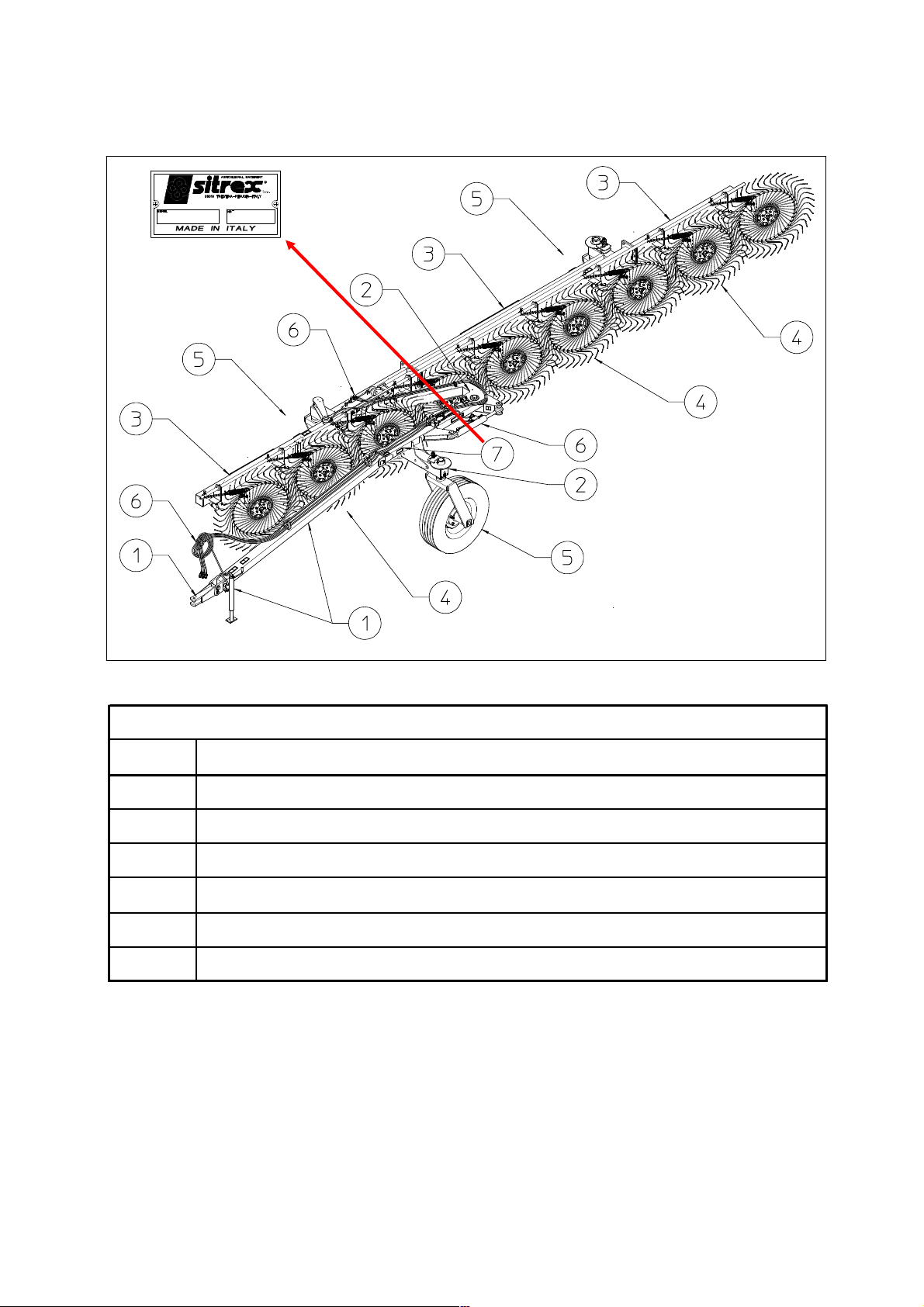
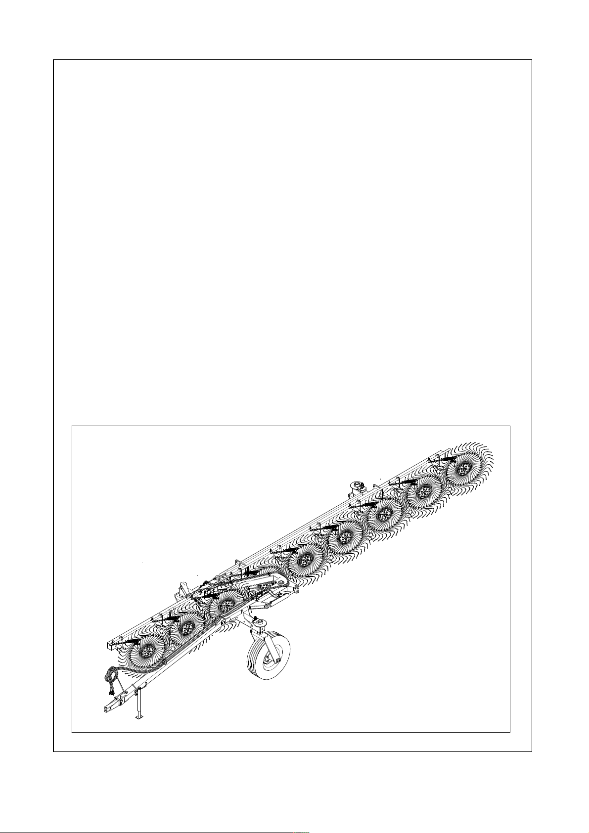
3) PRODUCT IDENTIFICATION
1
2
3
4
5
6
7
DRAWBAR AND ACCESORIES FOR TRANSPORT
FRAME
RAKE SECTIONS
RAKE WHEELS AND ACCESORIES
WHEELS AND TRAILER ACCESSORIES
HYDRAULIC SYSTEM
IDENTIFICATION PLATE
MAIN PARTS
7
Page 8
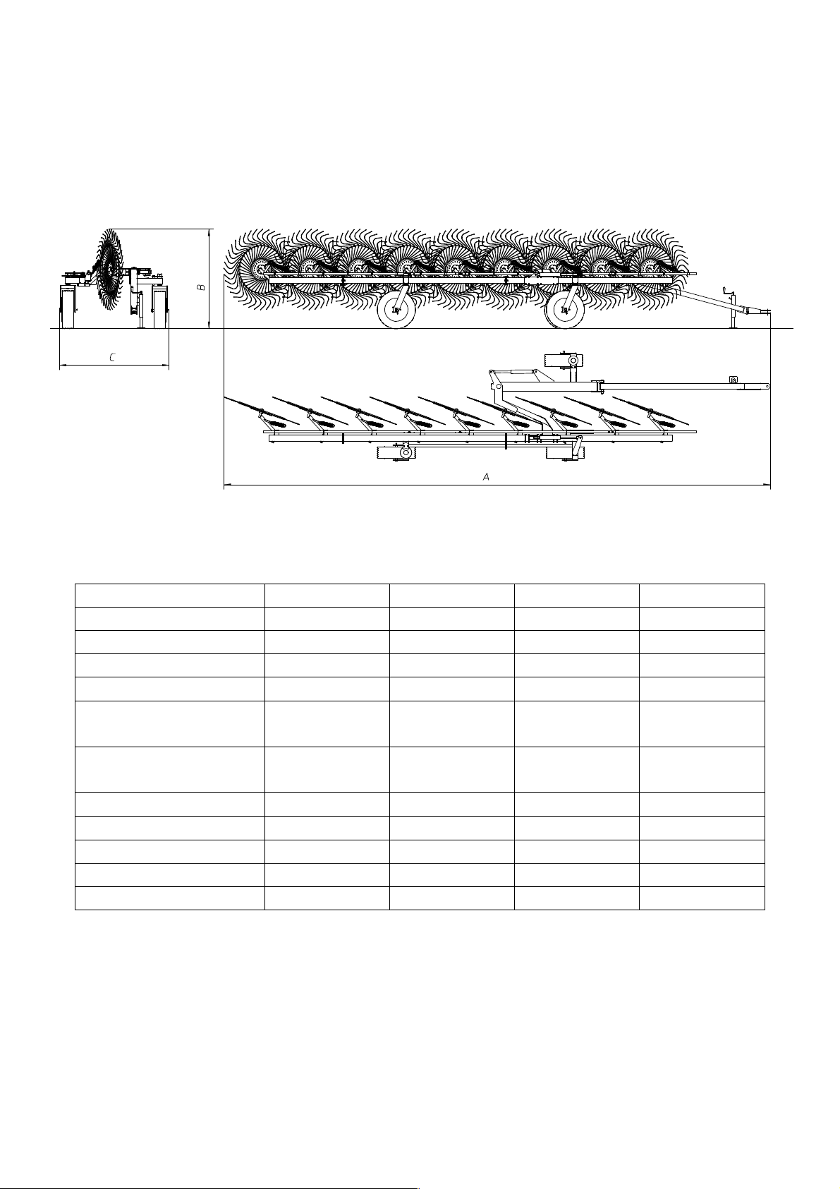
3) TECHNICAL SPECIFICATIONS
MODELS TR/6-S TR/8-S TR/7-S TR/9-S
Weight
Overall length (A)
Transport height (B)
Transport width (C)
710 Kg / 1565 lbs 780 Kg / 1720 lbs 735 Kg /1620 lbs 815 Kg /1795 lbs
7.1 m / 23' 8.75 m / 26'3" 7.95 m / 23'4" 9.65 m / 31'6"
1.7 m / 67" 1.7 m / 67" 1.7 m / 67" 1.7 m / 67"
1.95 m / 77" 1.95 m / 77" 1.95 m / 77" 1.95 m / 77"
Number of rake
wheels
6 8 7 9
Number of tines on
each rake wheel
Tines diam.
Wheel diam.
Raking working width
Working speed
22 kmh / 14 mph 22 kmh / 14 mph 22 kmh / 14 mph 22 kmh / 14 mph
HP required min.
The data are approximate. The manufacturer reserves the right to change them at any time without notice.
40 40 40 40
7mm/0.3" 7mm/0.3" 7mm/0.3" 7mm/0.3"
1.4 m / 55" 1.4 m / 55" 1.4 m / 55" 1.4 m / 55"
4 m / 13'2" 5 m / 16'5" 4.5 m / 14'9" 5.5 m / 18'
30 Hp / 26 Kw 30 Hp / 26 Kw 30 Hp / 26 Kw 30 Hp / 26 Kw
8
Page 9
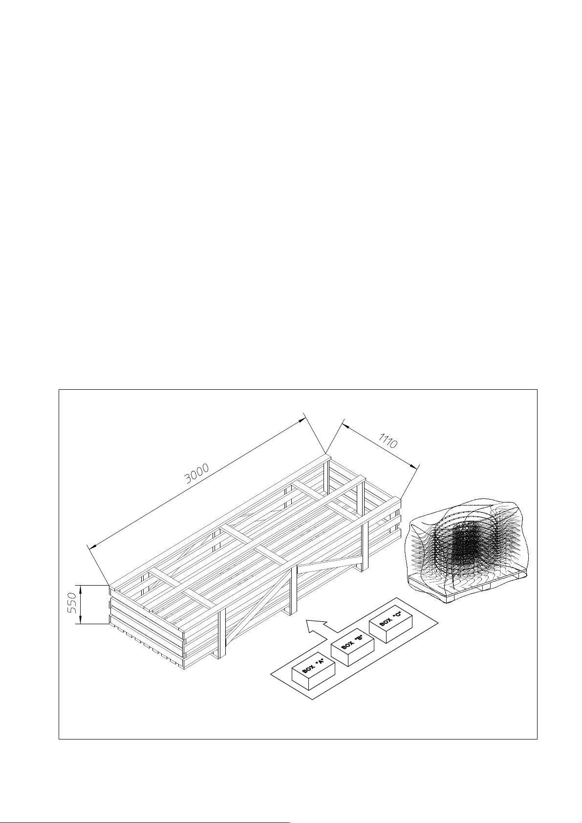
4) DELIVERY, CHECKING AND ASSEMBLY OF THE MACHINE
Delivery and unpacking.
The machine is delivered partially assembled in one crate and one pallet containing
the rake wheels. In the crate there are the parts to be assembled and three cardboard
boxes (marked “A”, “B”, “C” ) which contain the accessories for assembly (nuts and
bolts, couplings, pins, etc.).
On the pallet there are 9 (or 8/or 7/or 6) RH rake wheels.
All components are checked before being shipped by the manufacturer. Upon receipt
of the machine, check that the crates are in good condition and that the contents have
not been damaged during transport. If there is any damage and/or irregularities, notify
your dealer immediately.
Note: the packing materials consist of wood, plastic film, cardboard and steel
supports, and must be disposed in accordance with your local laws.
Handle the crates and pallets using forklifts that are suitable both for lifting the
weight indicated and for giving stability to the crates and pallets in consideration of
their size and shape.
9
Page 10

Assembly Instructions
Examples of general measurements for identifying assembly accessories according to
type.
To make it easier to identify the assembly accessories (nuts, bolts, washers, pins, etc.)
on the basis of the general dimensions and the type, we provide a diagram that shows
you the accessory parts to which the measurements refer as given in the various steps
of assembly.
The drawings are schematic and do not always faithfully reproduce the accessories,
but they will be of help in identifying them correctly.
Note: the accurate measurements are those given in mm; those given in inches are
rounded off, and for threads the size in inches is given only as an aid, as it does not
accurately describe the thread.
You can see the following examples:
Box “A”: shows springs that are will be identified by the wire diameter, the outside
diameter and the length, thus in this case ø3-ø18x110 (ø0.12”-ø0.71”x4.33”)
Box “B”: shows handles, spring pins, split pins, etc. that will be identified by the
diameter of the shank and the length, thus in this case ø8 x 50 (ø0.12” x 1.97”)
Box “C”: shows shims, bushings, spacers and washers in general that will be
identified by the inside diameter, the outside diameter and the length and/or the
thickness (for washers), thus in this case ø18-ø35 x 30 (ø0.71”-ø1.38” x 1.18”) or for
washers ø18-ø35 x 3 (ø0.71”-ø1.38” x 0.12”).
Box “D”: shows retaining rings for internal housings/bores that will be identified by
the diameter of the bore preceded by an I, thus in this case I35-1.38”, and for external
shafts that will be identified by the diameter of the pin preceded by an E, thus in this
case E35-1.38”.
Box “E”: shows pins, bolts, etc. that will be identified by the outside diameter (thread
diameter for bolts) and the length, thus in this case ø20 x 70 (ø0.78” x 2.76”) or for
bolts M20 x 70 (0.78” x 2.76”).
Box “F”: shows nuts and grease nipples that will be identified by the thread diameter,
thus in this case M10 (0.39”).
Box “G”: shows R-clips that will be identified by the diameter of the shank, thus in
this case ø3 (ø0.12”).
10
Page 11

Assembly Instructions
Examples of general measurements for identifying accessories for
assembly according to type.
For tightening torques, see the table below (the class of the material is normally
stamped on the head of the bolts).
11
Page 12
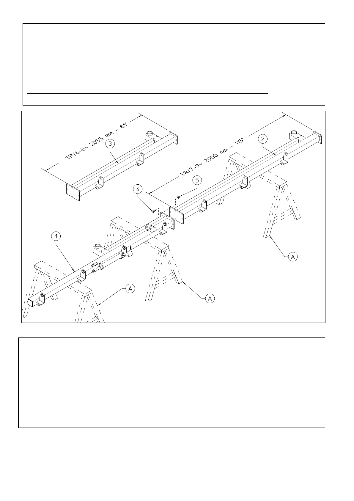
ASSEMBLY SEQUENCE
The machine must be assembled in a suitable area, done by qualified personnel
equipped with the proper clothing, protective equipment and tools necessary for the job.
Only authorized persons should be in the assembly area.
Always use great caution because the assembly steps are dangerous.
1) DANGER
Place the section 1 on the supports A.
Attach section 1 to section 2 (TR/7-9) or 3 (TR/6-8) using bolts 4 and nuts 5.
Place the section 2 (or 3) on support A.
In this step, you will use:
Item 4: 8 bolts M16x45 (0.63”x1.77”)
Item 5: 8 nuts M16 (0.63”)
12
Page 13
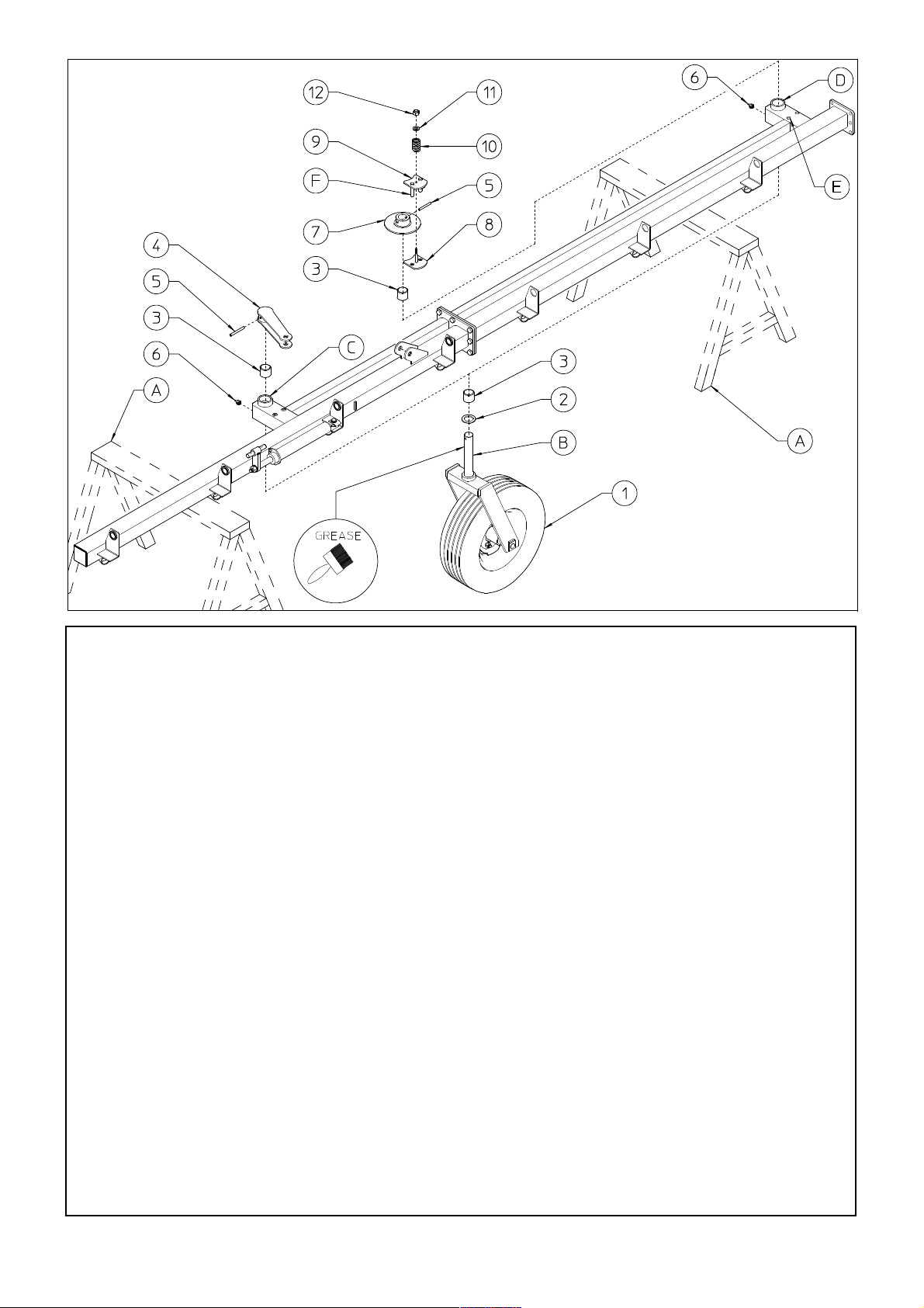
2) DANGER
Before attaching the wheel units 1, brush pin B and spring pins 5 with grease.
Insert the nylon bushings 3 into the proper seats C-D. Place spacer 2 on the pins B of the
wheel units 1. Insert the wheel units 1 into the proper seat C. Attach the lever 4 into the pins B
of the wheel units 1 using the spring pins 5. Attach the grease nipples 6 to the proper seat C.
Insert the wheel units 1 into the proper seat D. Attach the flange 7 into the pins B of the wheel
units 1 using the spring pins 5. Attach the plate with bolt 8 underneath flange 7. Attach the
brake plate 9 over flange 7, inserting the brake plate pins F into the holes in the plate with bolt
8 and into holes E in the sections. Place the spring 10, and washer 11 over the plate with bolt 8
and put nut 12 on the bolt.
Note: the more spring 10 is compressed by tightening nut 12, the more the turning of the
wheel is braked, therefore check that it is adjusted properly when the machine is to be
operated . Attach the grease nipples 6 to the proper seat D.
In this step, you will use:
Item 2: 2 spacers ø50-76x5 (1.97”x3”)
Item 3: 4 nylon bushings ø50-60x50 (ø1.97”-2.36x1.97”)
Item 5: 2 spring pins ø10x80 (0.4”x3.15”)
Item 6: 2 grease nipples M8 (0.31”)
Item 10: 2 springs ø5-30x45 (0.20”-1.18”x1.77”)
Item 11: 2 washers ø12-36x4 (ø0.47”-1.42x0.16”)
Item 12: 2 nuts M12 (0.47”)
13
Page 14
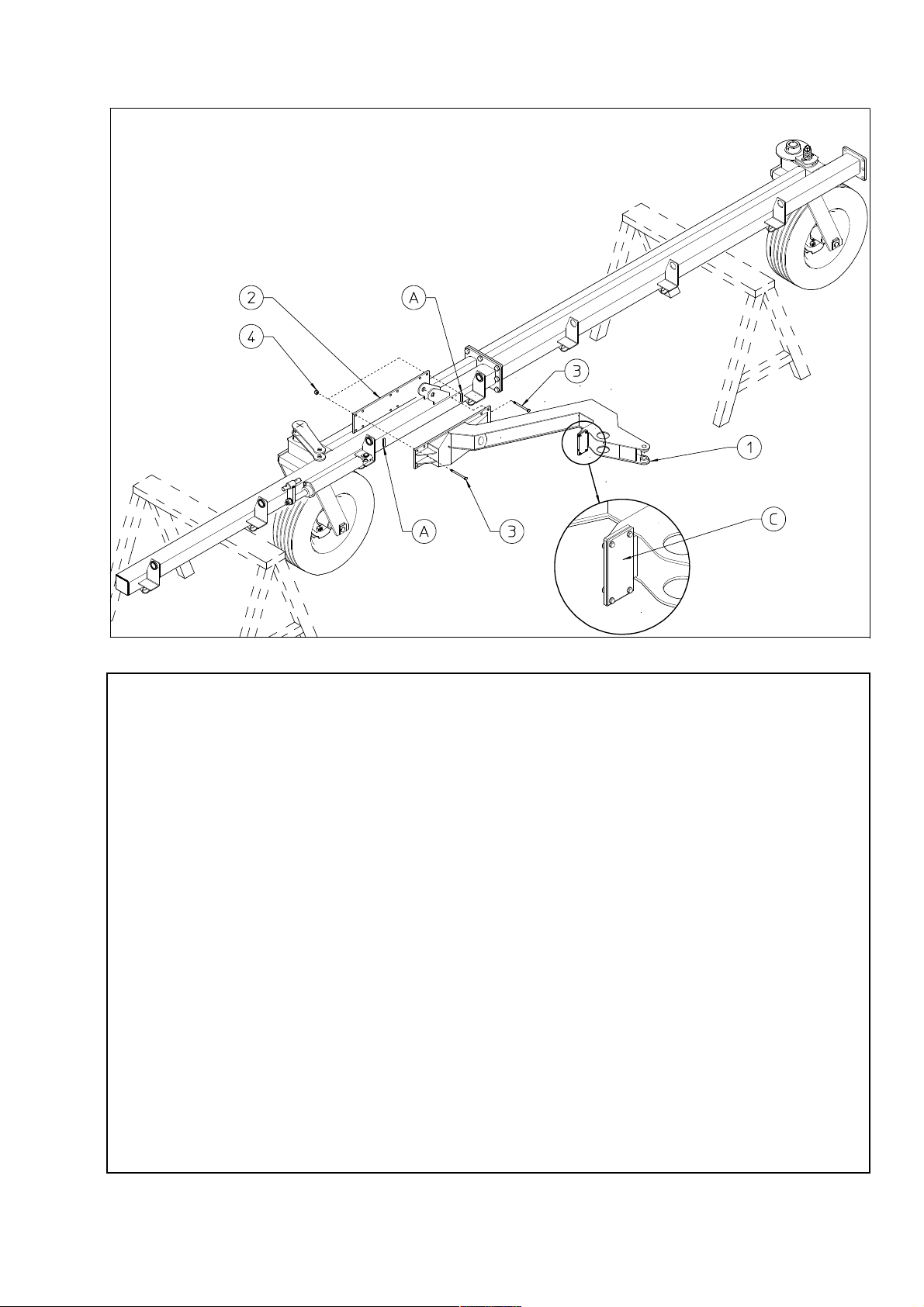
3) DANGER
Carry out this operation very carefully and with suitable lifting equipment because
the support 1 is heavy and bulky.
First of all make sure that the manufacturer has installed the rubber bumper B on
support 1.
Support 1 must be positioned between the retainers A.
Attach the support 1 to sections by means of the counterplate 2, bolts 3 and nuts 4.
In this step, you will use:
Item 6: 12 bolts M14x140 (0.55”x5.51”)
Item 7: 12 nuts M14 (0.55”)
14
Page 15
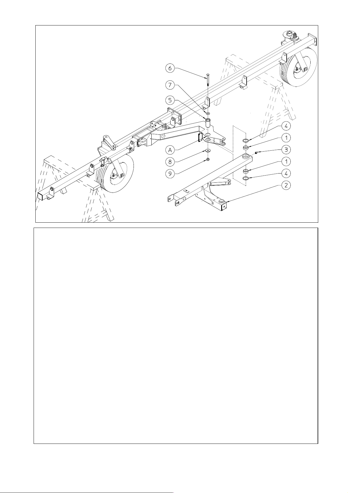
4) DANGER
Attach the nylon bushings 1 to the proper seats. Attach the grease nipple 3 to the
proper seat.
Connect support 2 to seat A on the arm using pin 5, shims 4, bolt 6, washers 7-8
and nut 9.
In this step, you will use:
Item 1: 2 nylon bushings ø75-85x30 (ø2.95”-3.35”x1.18”)
Item 3: 1 grease nipple M8 (0.31”)
Item 4: 2 shims ø75-100x1 (ø2.95”-3.94”x0.04”)
Item 5: 1 pin ø 75x115 (2.95” x 4.53”)
Item 6: 1 bolt M24x165 (0.94”x6.5”)
Item 7: 1 washer ø25-64x10 (ø1”-2.52”x0.4”)
Item 8: 1 washer ø25-90x10 (ø1”-3.54”x0.4”)
Item 9: 1 nut M24 (0.94”)
15
Page 16
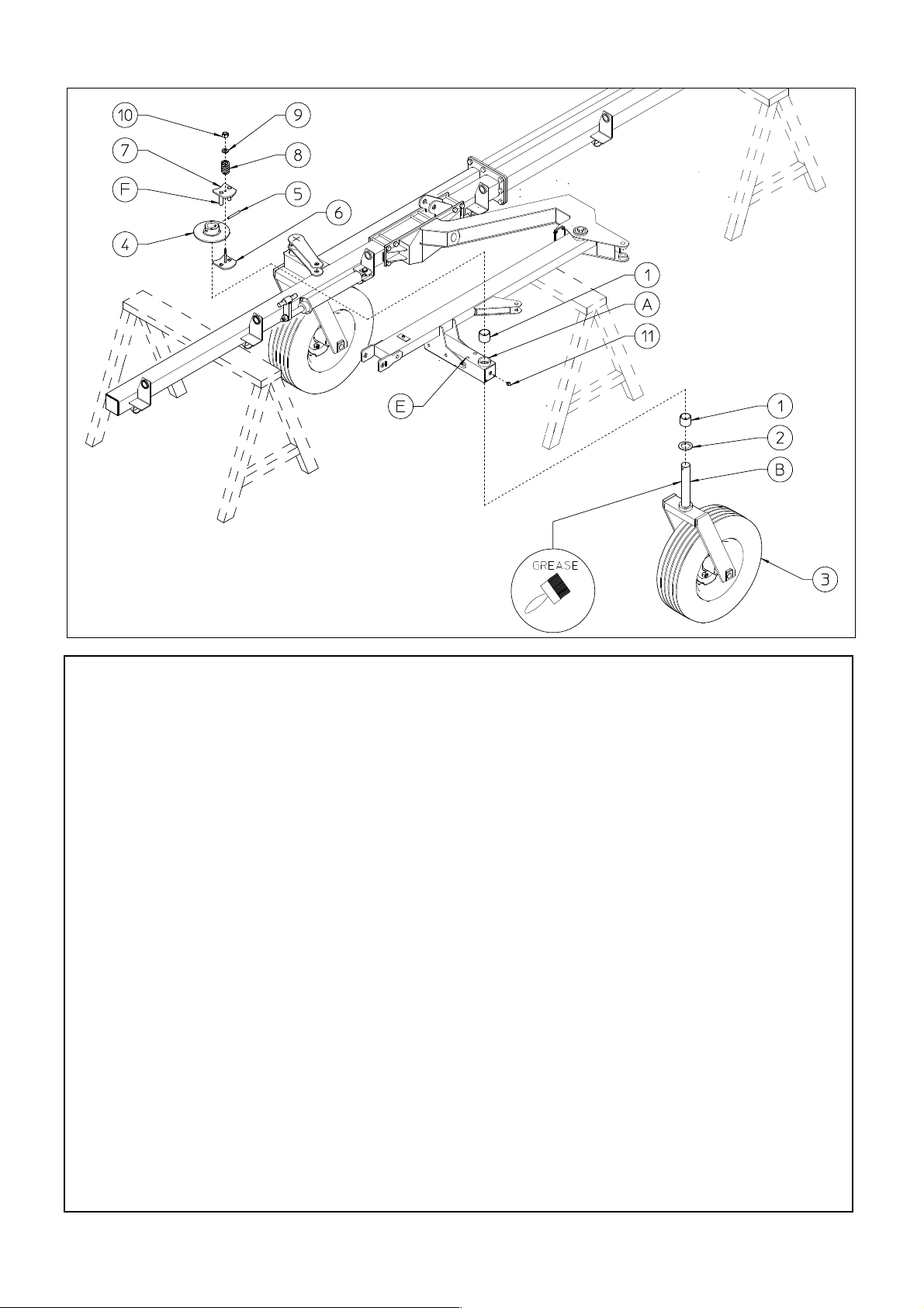
5) DANGER
Before attaching the wheel unit 3, brush pin B and spring pin 5 with grease.
Insert the nylon bushings 1 into the proper seats A. Place spacer 2 on the pins B of the wheel
units 3. Insert the wheel units 3 into the proper seat A. Attach the flange 4 into the pins B of
the wheel units 3 using the spring pin 5. Attach the plate with bolt 6 underneath flange 4.
Attach the brake plate 7 over flange 4, inserting the brake plate pins F into the holes in the
plate with bolt 6 and into holes E in the support. Place the spring 8, and washer 9 over the
plate with bolt 6 and put nut 10 on the bolt.
Note: the more spring 8 is compressed by tightening nut 10, the more the turning of the wheel
is braked, therefore check that it is adjusted properly when the machine is to be operated.
Attach the grease nipple 11 to the proper seat.
In this step, you will use:
Item 1: 2 nylon bushings ø50-60x50 (ø1.97”-2.36x1.97”)
Item 2: 1 spacers ø50-76x5 (ø1.97”-3x0.2”)
Item 5: 1 spring pin ø10x80 (0.4”x3.15”)
Item 8: 1 spring ø5-30x45 (0.20”-1.18”x1.77”)
Item 9: 1 washer ø12-36x2.5 (ø0.47”-1.42x0.1”)
Item 10: 1 nut M12 (0.47”)
Item 11: 1 grease nipples M8 (0.31”)
16
Page 17
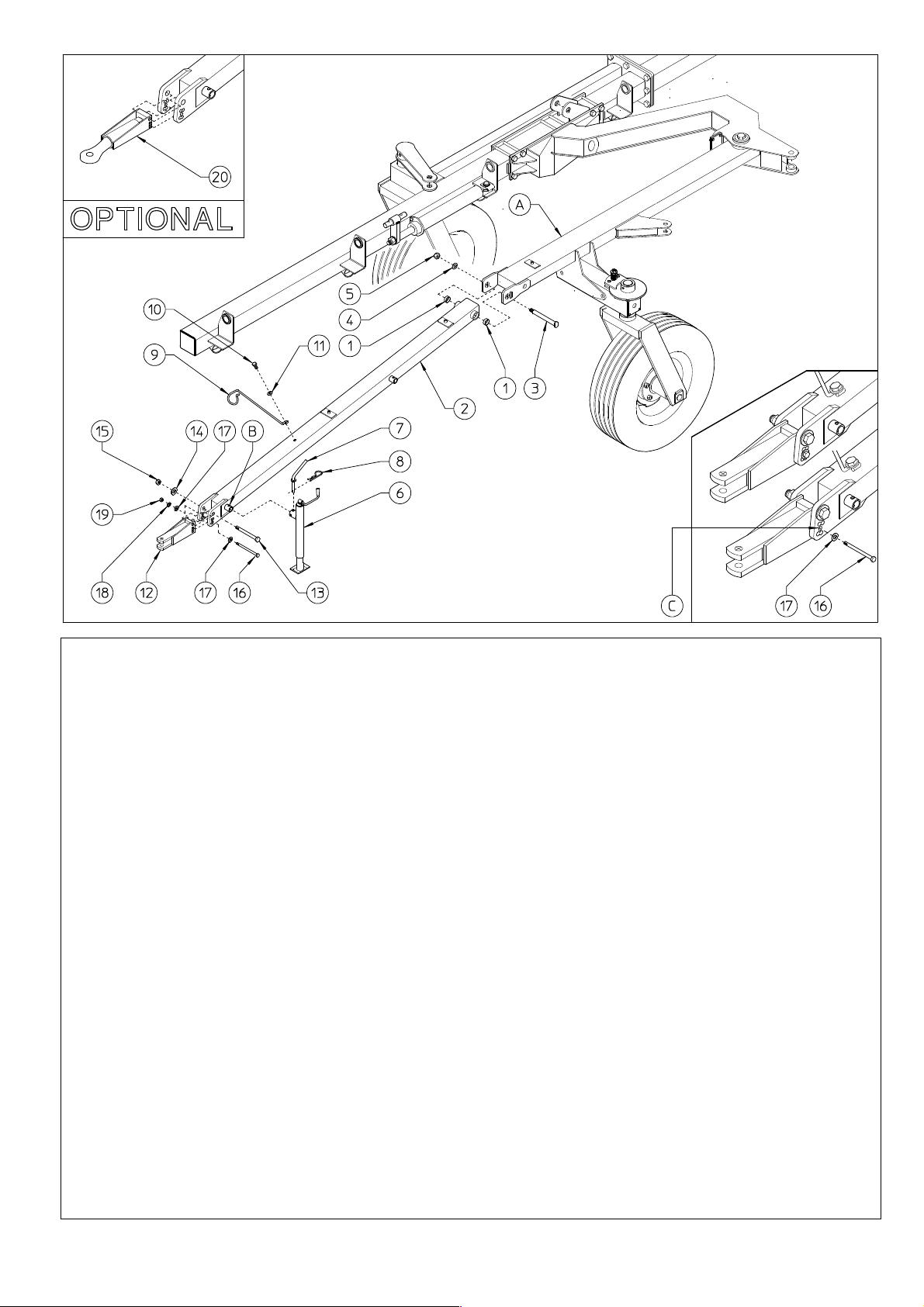
6) DANGER
Attach the bushings 1 to the proper seats. Now attach drawbar 2 to support A using pin 3, washer
4 and nuts 5. Attach the stand 6 to seat B on drawbar 2 using the pin 7 and clip 8. Assemble the
hose support 9 with the screw 10 and nut 11.
Attach the tractor hitch 12 to the hole B on drawbar 2 using screw 16, washers 17-18 and nut 19.
NOTE: The optional hitch 20 is installed following the same procedure as that for the standard
hitch 12.
In this step, you will use:
Item 1: 2 bushings ø35-39x30 (1.38”-1.54“x1.18”)
Item 3: 1 pin ø35x184 (1.38”x7.24”)
Item 4: 1 washer ø23-50x4 (0.91”-1.97”x0.16”)
Item 5: 1 nut M22 (0.87”)
Item 7: 1 pin ø15x78 (ø0.59x3.07”)
Item 8: 1 clip ø3 (ø0.12”)
Item 10: 1 bolt M12x25 (0.47”x1”)
Item 11: 1washer ø12-40x4 (0.47-1.57x0.16”)
Item 13: 1 bolt M20x140 (0.78”x5.51”)
Item 14: 1 spring washer ø21 (0.83”)
Item 15: 1 nut M20 (0.78”)
Item 16: 1 bolt M12x140 (0.47x5.51”)
Item 17: 2 washers ø12-36x2.5 (0.47-1.42x0.1”)
Item 18: 1 spring washer ø13 (0.94”)
Item 19: 1 nut M12 (0.47”)
17
Page 18
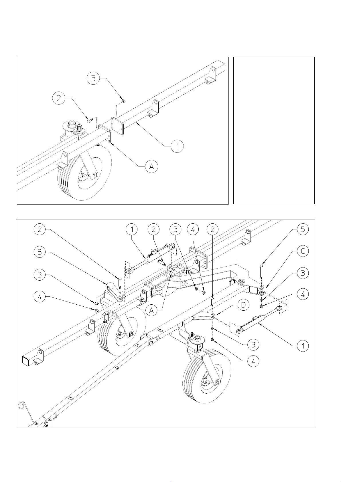
7) DANGER
For TR/8-9 only
Attach the section 1 to
section A using screws
2 and nuts 3.
In this step, you will
use:
Item 4: 6 bolts M16x45
(0.63”x1.77”)
Item 5: 6 nuts M16
(0.63”)
18
Page 19
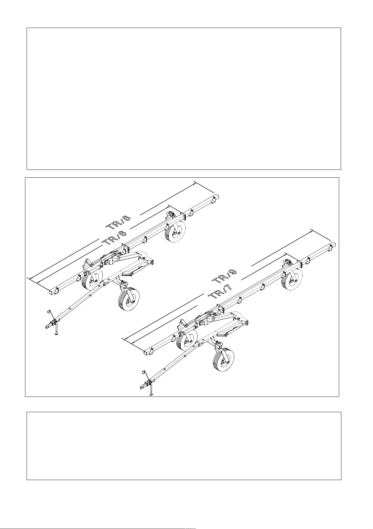
8) DANGER
(see drawing on preceding page)
Attach the cylinder 1 at seat A on the section and seat B on lever. Fasten them to seats A-B
with pins 2, washers 3 and nuts 4. Attach the cylinder 1 at seat C on the arm and seat D on
wheel support. Fasten them to seat D with pins 2, washers 3 and nuts 4 and to seat C with
pins 5, washers 3 and nuts 4.
In this step, you will use:
Item 2: 3 pins ø25x58 (ø1”x2.28”)
Item 3: 4 washers ø23-50x4 (ø0.91”-1.97”x0.16”)
Item 4: 4 nuts M22 (0.87”)
Item 5: 1 pin ø25x116 (ø1”x4.57”)
9)
You have now reached this stage of the assembly. The machine rests on its wheels and
thus has good stability. However, continue to use great caution during the rest of the
assembly, so as to work safely. In order to work better, spread apart the right and left
sections of the machine.
19
Page 20
20
Page 21

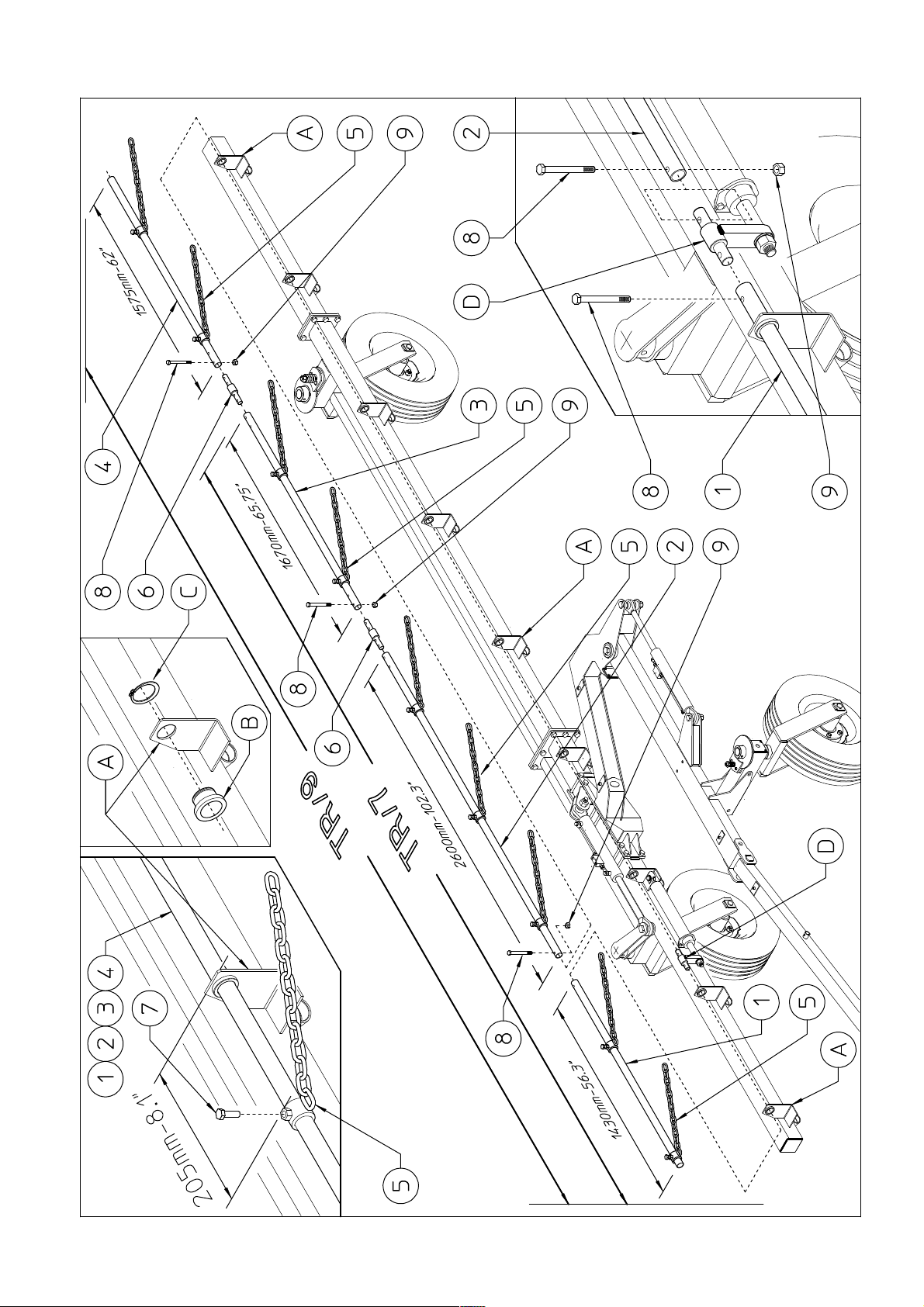
10) DANGER
For TR/7-9 only
Check to make sure the manufacturer has correctly secured the bushings B with
retaining rings C on brackets A on all the sections.
Pipe 1 is inserted starting from bracket A at the front of the machine, while pipes 23-4 are inserted from bracket A at the back of the machine. At the same time the
bushings with chain 5 must be put on the pipes at the positions shown (205 mm –
8.1” from bracket A). Join pipe 1 to pin D using bolt 8 and nut 9. Join pipe 2 to pin
D using bolt 8 and nut 9. Join pipe 3 to pipe 2 using pin 6 ,bolts 8 and nuts 9. Join
pipe 4 to pipe 3 using pin 6 ,bolts 8 and nuts 9.
At this point fasten the bushings with chain 5 to the pipes 1-2-3-4 at the position
indicated using bolts 7.
In this step, you will use:
Item 6: n° 1-2 pins ø22-35x198 (ø0.877”-1.38”x7.8”)
Item 7: n° 7-9 bolts M10x25 (0.39” x 1”)
Item 8: n° 6-10 bolts M8x45 (0.31”x1.77”)
Item 9: n° 6-10 nuts M8 (0.31”)
21
Page 22
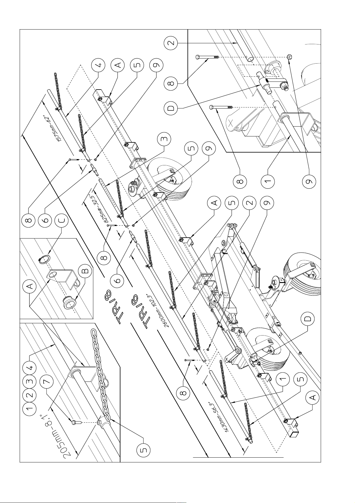
22
Page 23

11) DANGER
For TR/6-8 only
Check to make sure the manufacturer has correctly secured the bushings B with
retaining rings C on brackets A on all the sections.
Pipe 1 is inserted starting from bracket A at the front of the machine, while pipes 2-34 are inserted from bracket A at the back of the machine. At the same time the
bushings with chain 5 must be put on the pipes at the positions shown (205 mm – 8.1”
from bracket A). Join pipe 1 to pin D using bolt 8 and nut 9. Join pipe 2 to pin D using
bolt 8 and nut 9. Join pipe 3 to pipe 2 using pin 6 ,bolts 8 and nuts 9. Join pipe 4 to
pipe 3 using pin 6 ,bolts 8 and nuts 9.
At this point fasten the bushings with chain 5 to the pipes 1-2-3-4 at the position
indicated using bolts 7.
In this step, you will use:
Item 6: n° 1-2 pins ø22-35x198 (ø0.877”-1.38”x7.8”)
Item 7: n° 6-8 bolts M10x25 (0.39” x 1”)
Item 8: n° 6-10 bolts M8x45 (0.31”x1.77”)
Item 9: n° 6-10 nuts M8 (0.31”)
23
Page 24
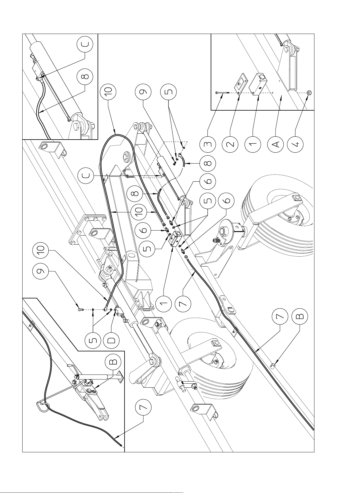
24
Page 25

12) DANGER
Fasten the flow divider 1 and the hose support 2 to frame A using bolts 3 and nuts
4.
Apply washers 5 and nipples 6 to three holes on the flow divider 1. Connect the
hose 7 to nipples 3. Extend the hose 7 along the drawbar B. Connect the hose 8 to
nipples 3. Connect the hose 8 to cylinder check valves C using washers 5 and
screw 9. Connect the hose 10 to nipples 3. Connect the hose 10 to cylinder check
valves D using washers 5 and screw 9. Note: before fully fastening hoses 7-8-10,
make sure that the line of each hose from one end to the other is not twisted and/or
does not have sharp bends or kinks that cause it to be crushed or to have an
unpleasant appearance.
Hoses 7-8-10 will also be in the following steps.
In this step, you will use:
Item 3: 2 bolts M6x140 (0.47”x5.51”)
Item 4: 2 nuts M6 (0.24”)
Item 5: 7 washers ø3/8”
Item 6: 3 nipples 3/8”-1/4”
Item 7: 1 hose, ¼”, length 5200 (205”)
Item 8: 1 hose, ¼”, length 460 (18.1”)
Item 9: 2 screw-type couplings 3/8”
Item 10: 1 hose, ¼”, length 2450 (97”)
25
Page 26
26
Page 27

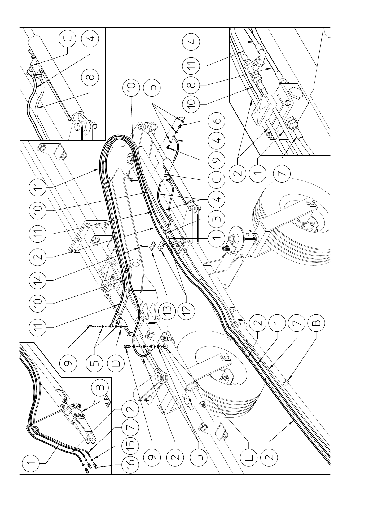
13) DANGER
Extend the hose 1 along drawbar B toward the front of the machine above to hose 7
already assembled. Extend the hose 2 along drawbar B toward the front of the
machine parallel to hose 1. Extend the hose 2 along hose 10 already assembled
toward the cylinder E. Connect the hose 2 to the cylinder E using washers 5 and
screw 9. Fasten the hoses 1-2 using hose collars 12, plate 13 and screw 14. Connect
the fitting 3 to the hose 1. Connect the hose 4 to the fitting 3. Connect the hose 4 to
cylinder check valves C using washers 5, fitting 6 and screw 9.
Connect the hose 11 to the fitting 3. Extend the hose 11above hose 10 already
assembled toward the cylinder check valves D. Connect the hose 11 to the cylinder
check valves D using washers 5 and screw 9. Connect the washers 15 and the quickrelease couplings 16 to the male ends of hoses 1-2-7.
Note: before fully fastening hoses 1-2-4-7-8-10-11, make sure that the line of each
hose from one end to the other is not twisted and/or does not have sharp bends or
kinks that cause it to be crushed or to have an unpleasant appearance.
In this step, you will use:
Item 1: 1 hose, ¼”, length 5350 (211”)
Item 2: 1 hose, ¼”, length 8100 (323”)
Item 3: 1“T“ fitting male ¼“
Item 4: 1 hose, ¼”, length 420 (17”)
Item 5: 7 washers ø3/8”
Item 6: 1 fitting male-female 3/8“
Item 7: see preceding step
Item 8: see preceding step
Item 9: 3 screw-type coupling 3/8”
Item 10: see preceding step
Item 11: 1 hose, ¼”, length 2350 (93”)
Item 12: 2 hose collars ø16 (0.63”)
Item 13: 1 plate
Item 14: 1 screw M8x35 (0.31 x 1.38”)
27
Page 28
28
Page 29

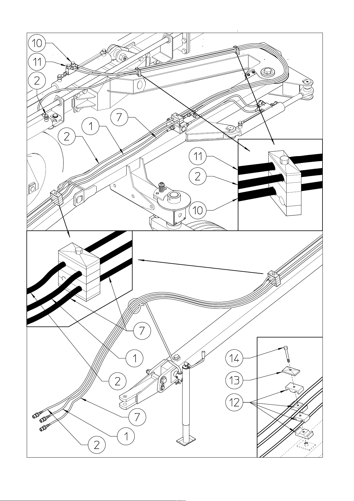
13) DANGER
Fasten the hoses 1-2-7 using hose collars 12, plate 13 and screw 14. Fasten the hoses
2-10-11 using hose collars 12, plate 13 and screw 14.
In this step, you will use:
Item 1-2-7-10-11: see preceding step
Item 12: 16 hose collars ø16 (0.63”)
Item 13: 4 plate
Item 14: 4 screw M8x35 (0.31 x 1.38”)
29
Page 30
30
Page 31

15) DANGER
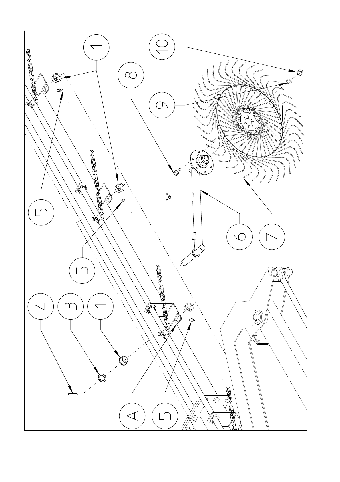
First insert the nylon bushings 1 in the all the seats A in all the sections. Next insert
the rake wheel arms 2 in all the seats A in all the sections and secure in place with
the washers 3 and spring pins 4.
Apply the grease nipples 5 to all the bushings A on all the sections.
Attach the rake wheels 6 to the arms 7 using the bolts 8, washers 9 and nuts 10.
In this step, you will use:
Item 1: 12-14-16-18 nylon bushings ø35-42x26 (ø1.38”-1.65”x1”)
Item 4: 6-7-8-9 washers ø35-50x5 (ø1.38”-1.97”x0.19”)
Item 5: 6-7-8-9 spring pins ø8x50 (ø0.31” x 1.97”)
Item 6: 6-7-8-9 grease nipples M6x45° (0.23”x45°)
Item 8: 36-42-48-54 bolts M10x25 (0.39”x1”)
Item 9: 36-42-48-54 split washers ø10.5-17x2.5 (ø0.41”-0.67”x0.1”)
Item 10: 36-42-48-54 nuts M10 (0.39”)
31
Page 32
32
Page 33
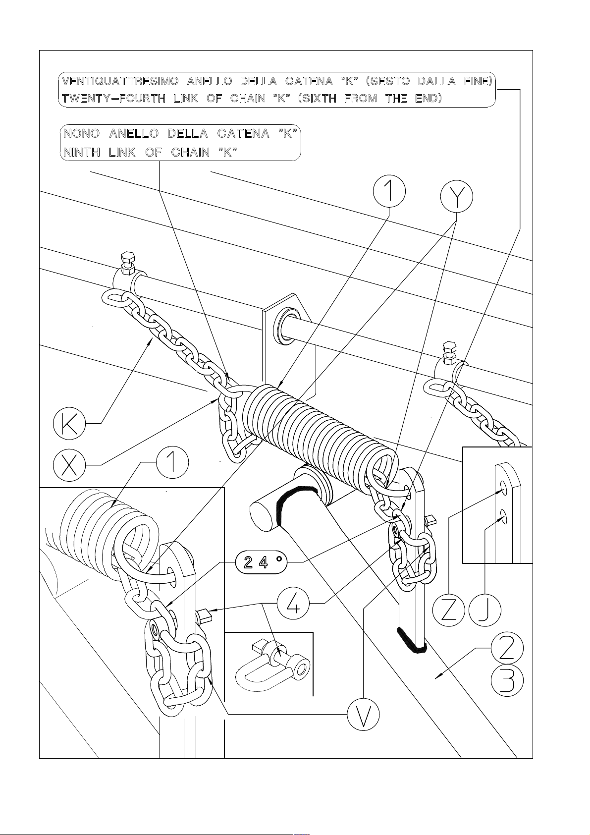
16) DANGER
Hook X on spring 1 is more closed than hook Y. Hook Y (the more open one)
should be inserted into hole Z in the lever of arms 2-3 (RH-LH).
First of all pass chain K, which is screwed onto the rake wheel lifting pipes,
through the spring 1. Then attach hook Y on spring 1 to hole Z in the lever of arms
2-3. Hook the 9th link of chain K (counting from that screwed onto the rake wheel
lifting pipes) to hook X on spring 1. Hook the last link V of chain K onto U-bolt 4,
then hook the 24th link of chain K (the 6th from the end), again by means of U-bolt
4, to hole J in the lever of arms 2-3. That described is the standard assembly of
chain K to spring 1. For working adjustments, see machine use.
In this step, you will use:
Item 1: 6-7-8-9 springs ø7-56x276 (ø0.27”-2.2”x10.87”)
Item 4: 6-7-8-9 U-bolts M8 (0.31”)
The assembly is now completed. The machine is ready to be lubricated and then
used.
33
Page 34
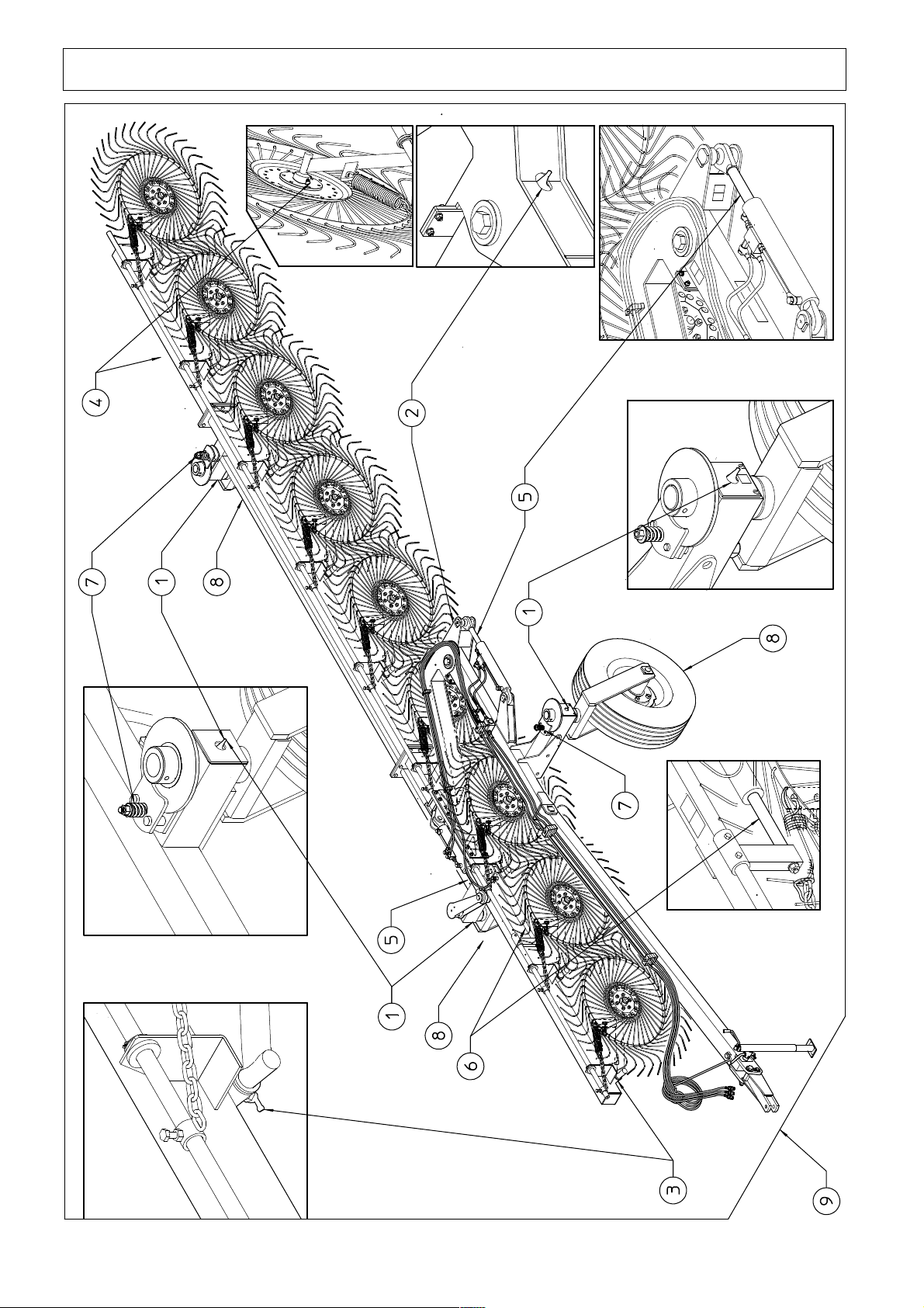
5) MAINTENANCE POINTS AND INSTRUCTIONS
34
Page 35
9
9
5) MAINTENANCE POINTS AND INSTRUCTIONS
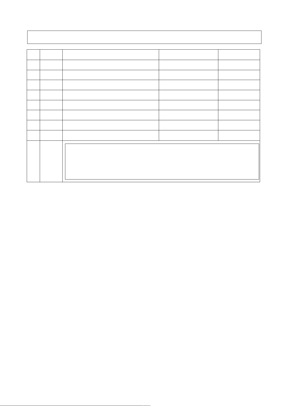
Pos. Qty. Description Operation Every x hours
1 3 Wheel support Lubricate 25
2 1 Frame Lubricate 25
3 6-7-8-
4 6-7-8-
Rake wheel arms Lubricate 16
Rake wheel hubs Lubricate 16
5 2 Opening cylinder shaft Clean-brush grease A
6 1 Rake wheel lifting cylinder shaft Clean-brush grease A
7 1 Pirouetting wheel brake Check effectiveness
8 3 Tires Check pressure C
B
Do the first general check after 8 working hours. Check
carefully the stability of the coupling of nuts and bolts, pins,
clips, tire pressure, etc. After this do a check every 50 working
hours.
9 *
Grease type: NLGI 1
A: Exposure to atmospheric agents subjects these parts to rusting, therefore each time
the machine is inactive for long periods (especially during the winter) brush the
cylinder shafts with grease. When possible keep the cylinders closed so that a
minimum amount of shaft is outside the cylinder barrel.
B: The wheels must pirouette freely, but without becoming uncontrollable. Check
the wear of the disks each season. (To adjust the brake, see machine use.)
C: Check the tire pressure each time the machine is used, especially after long periods
of inactivity. Bring the tires to the right pressure if necessary, according to the
indication on the tires.
35
Page 36
6)
ADJUSTMENT, PREPARATION AND USE
a) ATTACHING THE MACHINE TO THE TRACTOR
36
Page 37

6)
ADJUSTMENT, PREPARATION AND USE
a) ATTACHING THE MACHINE TO THE TRACTOR
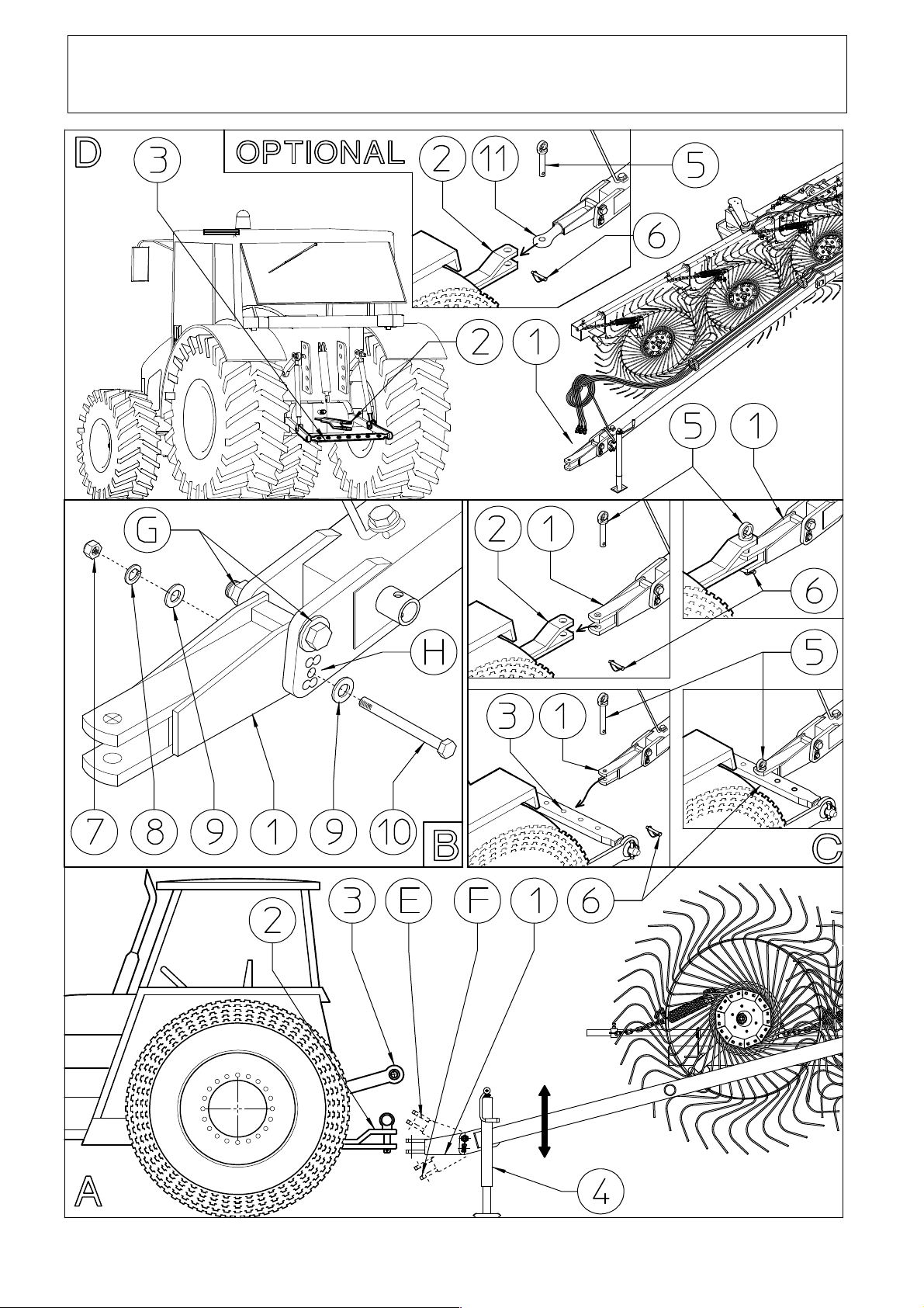
The attachment of the machine to the tractor is simple but dangerous. Carry out the
operation being extremely careful and strictly following these instructions. Make sure
that there are no persons or objects within the operating range of the machine and
tractor. Check that all the signs and symbols are on the machine and are legible.
Check that the tractor is in good condition and is suitable for pulling and working
with this machine. Always consult the tractor operator’s manual.
The attachment to the tractor consists of joining the machine’s hitch 1 to that of the
tractor 2 or to the bar 3 attached to the tractor lifting arms.
First of all (see Box A) bring the machine hitch 1 to the height of the tractor hitch 2
by adjusting the stand 4. (If instead you attach the machine to the bar 3, the correct
coupling height is achieved by raising or lowering the lifting arms).
Now, if the machine hitch 1 is roughly horizontal (parallel to the ground) you can
hitch it to the tractor. If instead the hitch 1 is inclined too much upward E or
downward F (see Box A), it must be brought back into a horizontal position. To do
this (see Box B) you must unscrew nut 7, remove washers 8, 9 and bolt 10. Now
rotate the hitch 1 and bring it to the hole H among the five holes available on the
drawbar that allows it to be fastened in a roughly horizontal position. If it is difficult
to rotate hitch 1, loosen the nut-screw unit G. To fasten hitch 1 in the chosen hole H,
use the bolt 10, the washers 9-8 and nut 7. Tighten the nut-screw unit G if it had been
loosened.
At this point, whether hitch 1 is attached to tractor hitch 2 or to the bar 3, you must
fasten it using a pin 5 of adequate size and capacity for the weight of the machine and
with a pin 6 (see Box C).
That described above also applies if the machine has been fitted with the optional
hitch 11 (see Box D).
NB: in this case, since the machine was assembled just before transporting it and
subsequently before working, you will have to do the functional tests (see paragraph
“b”), but this procedure should be carried out every time you have to attach the
machine to the tractor.
37
Page 38
b) PREPARING THE MACHINE FOR FUNCTIONAL TESTS.
38
Page 39

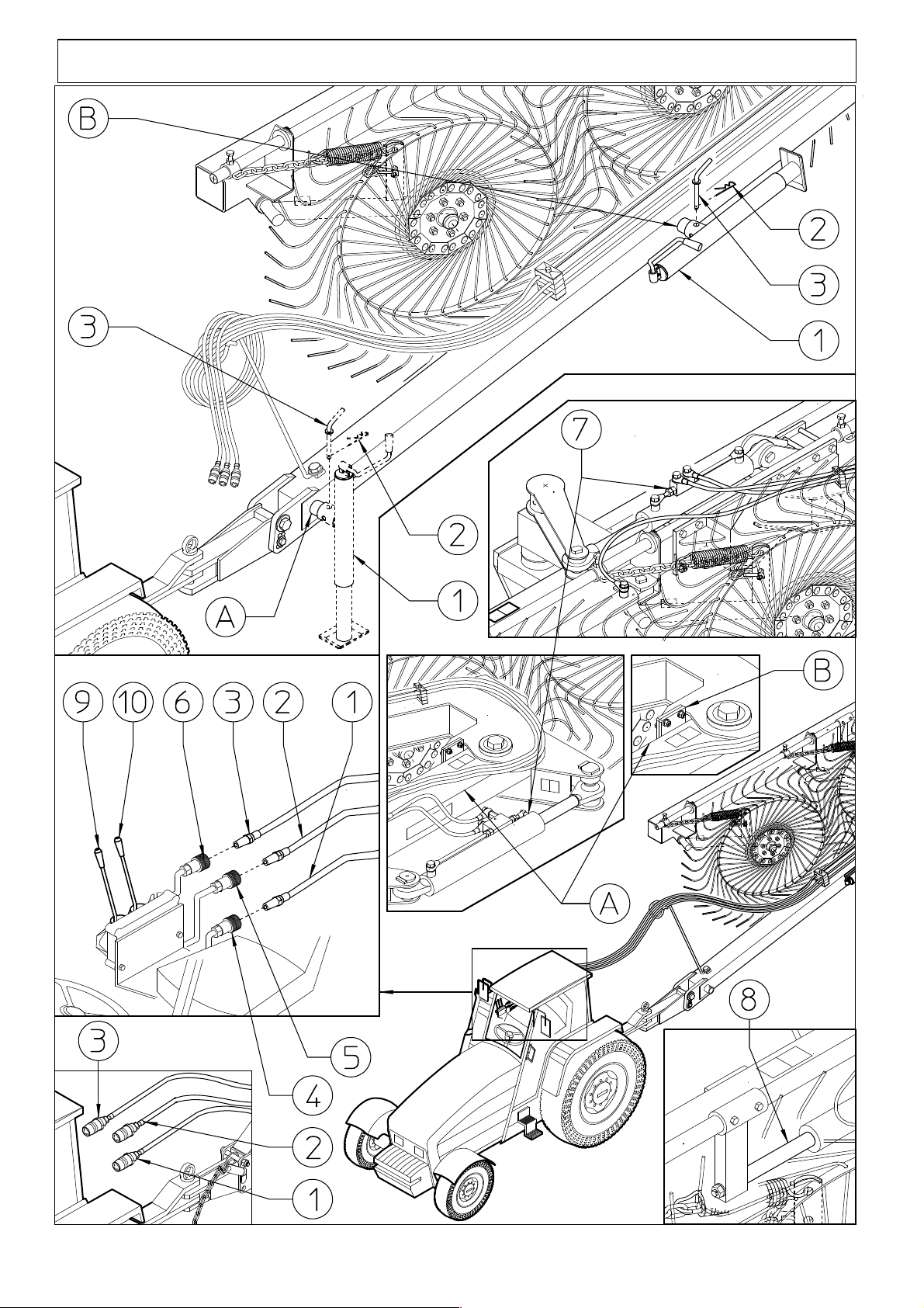
b) PREPARING THE MACHINE FOR FUNCTIONAL TESTS.
At this point remove the stand 1 from seat A (parking position) and bring it to seat B
(transport and working position). To do this you must remove clip 2 and pin 3, move
the stand 1 to position B and fasten it with pin 3 and clip 2.
NB: In this case, as the machine has just been assembled, the description given here
is intended for the functional tests before transporting it and subsequently before
working, but this procedure should be carried out every time you have to attach the
machine to the tractor.
Now connect the ends of hoses 1-2-3 to the tractor hydraulic couplings 4-5-6. By
moving lever 9, hoses 1-2 connected to hydraulic couplings 4-5 control cylinders 7
for opening/closing the machine (double acting). By moving lever 10, hose 3
connected to coupling 6 controls the rake wheel lifting cylinder 8 (single acting).
Note: The drawings of the hydraulic connections and levers are intended to give only
a general idea of their shape and position. Each tractor has its own specific shape and
location of these devices. At this point the machine is ready for its first starting,
which must be done following the procedures described herein.
Make sure that there are no persons within the operating range of the machine, then
move lever 9 to send oil to cylinders 7, which will start to shorten (or extend),
opening the wing of the machine. Once they are completely closed (or opened),
reverse the flow of the oil and have them return to the starting point. Do at least eight
to ten complete opening and closing cycles to expel the air from the cylinders and
from the hydraulic circuit. Close the cycle by making cylinders 7 open again
completely. With cylinder 7 completely open (machine closed), check that the frame
A is pressed tight against the rubber bumper B so that the machine is stable during
transport.
Now move lever 10 to send oil to cylinders 8, which will start to extend, raising the
rake wheels about 380-400mm – 15,5” from the ground. Cylinder 8 are the singleacting type, therefore their return to the initial position takes place to the effect of the
weight of the rake wheels. As these are small cylinders, four to five complete cycles
are enough to expel the air. Close the cycle by making cylinder 8 extend fully so that
the rake wheels are lifted off the ground. Now the machine is ready to be prepared for
transport. Before beginning the transport see the following point “c”.
39
Page 40
c) PREPARING THE MACHINE FOR TRANSPORT.
40
Page 41

c) PREPARING THE MACH
INE FOR TRANSPORT.
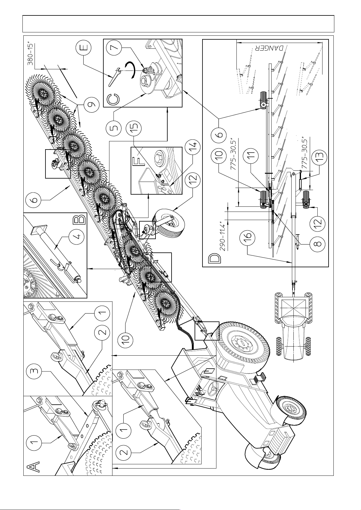
Before starting to transport the machine a series of checks and tasks must be done to
protect the safety of those who use the machine and of the persons and objects that are
on the road being traveled on, as well as to protect the machine itself from damage.
NOTE: That described above applies every time the machine is prepared for transport.
Check that the machine hitch 1 is securely attached to the tractor (see Box A) according
to that described in step “a” on pg. 36-37.
Check that the stand 4 is in the transport position (see Box B). Check that brake units 5
lets the wheels 6-12 turn freely but not uncontrollably. If the wheels 6-12 don’t turn
freely, loosen nut 7 as much as needed using wrench E; if instead it turns too freely, then
tighten nut 7 (see Box C). Check that cylinder 8 is extended (290 mm-11.4”) so that the
rake wheels 9 are raised about 380-400mm – 15 1/2” above the ground (southeast also
Box D).
Check that the front wheel 10 connected to cylinder 11 is parallel to drawbar 16. If it is
not, check the extension of cylinders 11-13. With the machine in the transport position,
cylinder 13 must be fully extended and reach the measurement of 775mm – 30.5” from
center to center. Consequently cylinder 11 must also reach the same measurement. If it
does not, use the tractor’s hydraulic system to send oil into the circuit so that cylinder 11
is also fully extended and thus brings wheel 10 connected to it into parallel with drawbar
16. If it is not possible to reach this condition, check the assembly of the various
components, check that there is enough oil in the tractor, that there are no leaks in the
hydraulic circuit, and no malfunctioning of the flow divider and/or the check valves.
NOTE: during transport wheel 10 must be parallel with drawbar 16. Wheels 6-12 must
turn freely but not uncontrollably (see Boxes C-D).
With cylinder 13 fully open (machine closed), check that the frame 14 is pressed tight
against the rubber bumper 15 so that the machine is stable during transport.
Keep in mind that during the transport, given the considerable length of this machine,
the rear side tends to move to the R or L (see box D) when changing direction of the
tractor; it can constitue a serious hazard for persons and/or objects that are in the
movement zone, therefore it is recommended that maximum caution be used.
Check that the tires 6-10-12 are at the pressure indicated.
If everything is ready, you may begin to transport the machine, keeping in mind that
which follows. The tractor must have specifications suitable for the transporting of this
machine, the driver must be fully qualified in every way to drive the tractor, and if
public roads are used, the driver must strictly observe all local traffic rules and
regulations.
41
Page 42
USE IN THE FIELD
a) GENERAL INSTRUCTIONS FOR USE IN THE FIELD
Before starting work, familiarize yourself with the controls and safety devices of the
machine and the tractor. Take into consideration the type of terrain (flat, rolling, hilly,
etc.) and its state (dry, wet, etc.).
Do not start working if any part or device on the machine and/or tractor is not in good
condition or even if you suspect that it is not.
Do not allow yourself to be distracted while working.
If you must work on inclined terrains, always work from the bottom to the top and
vice versa. If the shape of the field forces you to work across the incline, strictly
follow the instructions supplied in the tractor user’s manual regarding the maximum
incline on the two sides on which it is possible to work.
Always reduce the speed when working on terrains that are inclined, rough, wet,
grassy, rocky, etc.
If for any reason you must stop, choose a suitable position and carry out all the
necessary safety procedures.
When climbing in or out of the tractor do not use levers and/or controls as handholds,
because even with the engine shut off this could cause unexpected movements in the
tractor and/or machine, a serious hazard to both the driver and to those who are
nearby.
42
Page 43
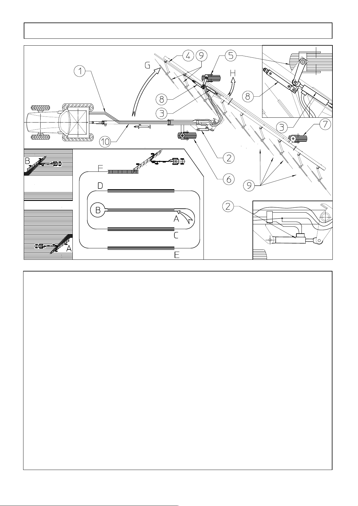
b) How to work
Use great caution because the change from the transport to the work stage involves a
widening of the machine. Be aware of persons and objects that may accidentally be in
the vicinity. The change from the transport to work stage is simple and immediate. You
only need to send oil from the tractor (see step “b”, pg. 38-39) to the hydraulic circuit 1
of the machine so that cylinders 2-3 will retract. When retracting, cylinder 2 causes the
rake section 4 to rotate in the working direction G, while cylinder 3 retracting causes
wheel 5 to rotate in direction H so that it remains parallel to drawbar 10. Wheels 6-7 are
free and adjust their position following the trajectory determined by the tractor. The
working width can be controlled and changed from the tractor at any time. Each operator
establishes the correct width according to their needs and the forage conditions. (For the
various working widths, see page 8). Then, using the tractor hydraulic system 1, release
the oil from cylinder 8 so that it retracts and consequently brings the rake wheels 9 into
contact with the ground, i.e. in the working position. (Cylinder 8 is single acting, thus it
lowers due to the weight of the rake wheels 9, and therefore it will take a little while to
carry out the operation, especially when the oil is cold). For good raking of the forage
the teeth of the rake wheels 9 should brush lightly against the ground.
Now the actual work stage can begin, following the procedure A-B-C etc..
43
Page 44
b) How to work
44
Page 45
b) How to work
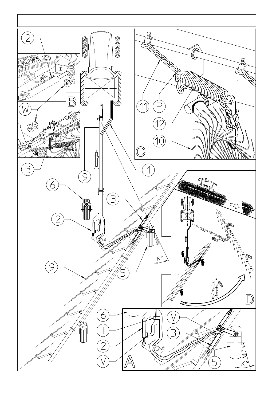
Adjustments:
-In continuous working conditions, on rough terrain and with high temperatures it can
occur that wheel 5 does not remain parallel to drawbar 9, but tends to become
misaligned (see angle K). If the misalignment K is considerable, it must be realigned. To
do this, use the controls for hydraulic system 1 on the tractor to open and close the
machine so that cylinders 2-3 extend and retract completely. At this point, reset the
appropriate raking width and continue working.
As mentioned, in normal working conditions (ground smooth and dry), on this type of
machine, you can work without any problems even with a misalignment K without
creating excessive problems for the tire.
- If the rake wheels 9 are too heavy, i.e. they dig into the earth, or too light, i.e. they
leave hay behind, they need to be lightened or made heavier by adjusting chain 10. If
you find that the rake wheels 9 are heavy, i.e. they dig into the earth too much, you can
move link P of chain 10 connected to spring 11 to the link before it, thus with chain 10
shorter it puts spring 11 under greater tension, lightening the rake wheels 9. If you find
that the rake wheels 9 are light, i.e. they leave hay behind, move link P to the next one,
thus chain 10 is longer and spring 11 is under less tension, making the rake wheels 9
heavier (see Box C).
Warning:
Use great caution when working downhill and on land sloping sideways with regard to
the machine, as the machine tends to slide forward (jackknife) toward the tractor (see
Box D).
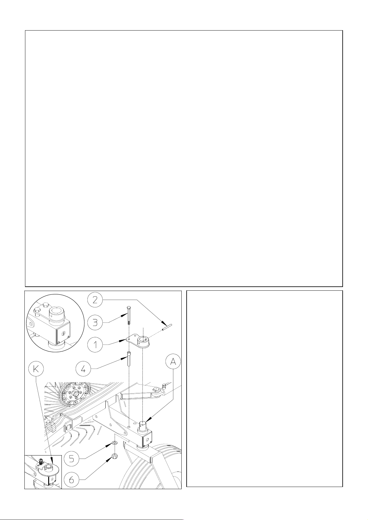
Moreover when working on sloping ground,
the machine tends to lose the right set of
work. In these cases it could be helpfull to
assemble a kit (OPTIONAL) that goes to
lock the oscillation of wheel 6.
To install the kit, you must first remove the
brake unit K.
Attach the lever 1 into the pins A of the
wheel units using the spring pins 2. Fixed
the lever 1 into the support using the screw 3,
bushing 4, washer 5 and nut 6.
In this step, you will use:
Item 2: 1 spring pin ø10x80 (0.4”x3.15”)
Item 3: 2 screw M12x160 (0.4”x3.15”)
Item 4: 2 spacers ø21-30x134 (ø0.83”-
1.18”x5.28”)
Item 5: 2 washers ø12-36x2.5 (ø0.47”-
1.42x0.1”)
Item 6: 2 nuts M12 (0.47”)
45
Page 46

GENERAL INSTRUCTIONS FOR REPAIR WORK
All repair work must be done by qualified personnel with the machine stationary and
detached from the tractor.
Do not do any welding or other important jobs without the authorization of and/or
instructions from the dealer and/or the manufacturer.
When welding, always disconnect the machine from the tractor to avoid damage to
the tractor. Always wear a protective mask, safety goggles, gloves and suitable
clothing when welding, sanding, grinding, using various tools or doing any type of
repair work. When welding in closed environments make sure that the area is
sufficiently ventilated to prevent the accumulating of noxious gases. If the machine
must be hoisted for repairs, use lifting equipment that is suitable for the job.
Never allow unauthorized persons to be in the repair area.
LAYING UP FOR LONG PERIODS
At the end of the season when the machine is laid up until the next season, or when it
will not be used for a fairly long period of time, it is recommended that the following
be done:
- Thoroughly clean and dry the machine;
- Check it carefully and replace any damaged or worn parts;
- Check and thoroughly tighten all screws and bolts where necessary;
- Lubricate and/or spread grease on the exposed parts of the cylinder shafts and the
adjustment screws and lubricate the areas provided for in the maintenance schedule,
then store the machine if possible in a dry sheltered place.
It is essential when restarting work to do an overall inspection of the machine
(especially if it has been stored in a not entirely suitable area) because time and
atmospheric agents cause the lubricants to deteriorate.
It is to the user’s advantage to follow these instructions, as it allows them to prolong
the life of the machine and to be certain that it will be working efficiently when work
is restarted.
46
Page 47

NOISE AND VIBRATIONS
The machine does not have any drive components, so the only noises it makes are
that of the teeth dragging on the ground and those caused by machine vibrations,
therefore the noise of the tractor always covers that of the machine.
INFORMATION ON SCRAPPING THE MACHINE
The machine consists mainly of ferrous material, which must be disposed of
according to the regulations in force in the country concerned.
The plastic and/or rubber parts must be disposed of according to the regulations in
force in the country concerned.
There is also a small amount of residual grease and oil, which must be disposed of
according to the regulations in force in the country concerned.
Do not release or otherwise dispose of any residues or remaining parts into the
surrounding environment.
47
Page 48

Zona Industriale-Viale Grecia, 8
06018 TRESTINA-(Perugia)-ITALY
Tel. +39.075.8540021-Telefax +39.075.8540523
e-mail: [email protected] www.sitrex.com
48
 Loading...