

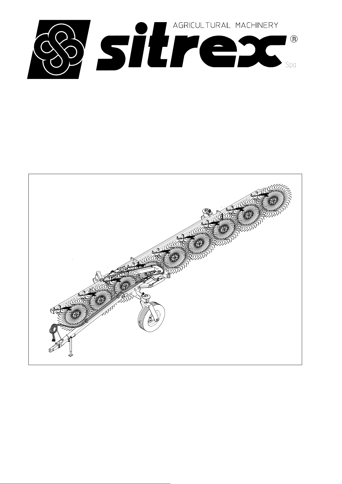
sitrex TR/6-S, TR/7-S, TR/8-S, TR/9-S Assembly, Use And Maintenance
ASSEMBLY
USE AND MAINTENANCE
TR/6-7-8-9 S
10-2014 FROM SERIAL NO. 255390

WARRANTY
When the machine is received, regardless of how it is delivered (in a crate,
partially assembled, assembled, etc.), the customer must check to make sure that
it is in good condition and that all components are present. To report any
damage, any missing parts or anything else that compromises the perfect
condition of the machine, submit a written claim to the sales agent and/or the
distributor and/or the manufacturer within eight days from the delivery date.
The warranty will not be recognized for problems that undoubtedly result from
unpacking, assembly or usage operations that do not comply with the provisions of
this manual.
The warranty will not be recognized if the customer is not able to return the defective
part (or parts) to the manufacturer, who therefore will not recognize any repair and/or
replacement costs, unless written agreements have been made between the customer
and the manufacturer or other persons authorized by the manufacturer. If there are
defective parts acknowledged preventively but not definitively by the manufacturer,
the buyer must return them (shipping costs covered) to the manufacturer who, after
verifying that they actually are defective, will repair or replace them and send them
back to the customer. If the manufacturer finds that the parts are not defective, the
customer will not be covered by the warranty.
The warranty is null and void if it is clear that the machine has been used improperly
and/or repaired without authorization.
The manufacturer shall not recognize any warranty in the case that its workers,
employees, agents, dealers or any others not specifically authorized by the
manufacturer should make agreements with the customer that do not fall within the
aforesaid conditions.
The warranty will be valid for a period of 12 (twelve) months starting from the date
of delivery to the original purchaser. This warranty substitutes any other warranty
expressed or implied by anyone, as well as any other obligation of the manufacturer.
NB: As specified, actions to be considered for replacement and repair under warranty
must first be approved by the manufacturer. The customer will not be reimbursed for
costs resulting from repairs and/or replacements made without the previous
authorization of the manufacturer. Before making repairs notify the manufacturer in
detail, so that it may evaluate whether to authorize the repair or to replace the part.
CHAPTER
1) GUIDE TO THE MEANING OF SIGNS AND SYMBOLS
2) Summary of safety and accident prevention regulations
3) PRODUCT IDENTIFICATION ANDTECHNICAL SPECIFICATIONS
4) DELIVERY OF THE MACHINE AND ASSEMBLY
5) MAINTENANCE POINTS AND INSTRUCTIONS
6) ADJUSTMENT, PREPARATION AND USE
2
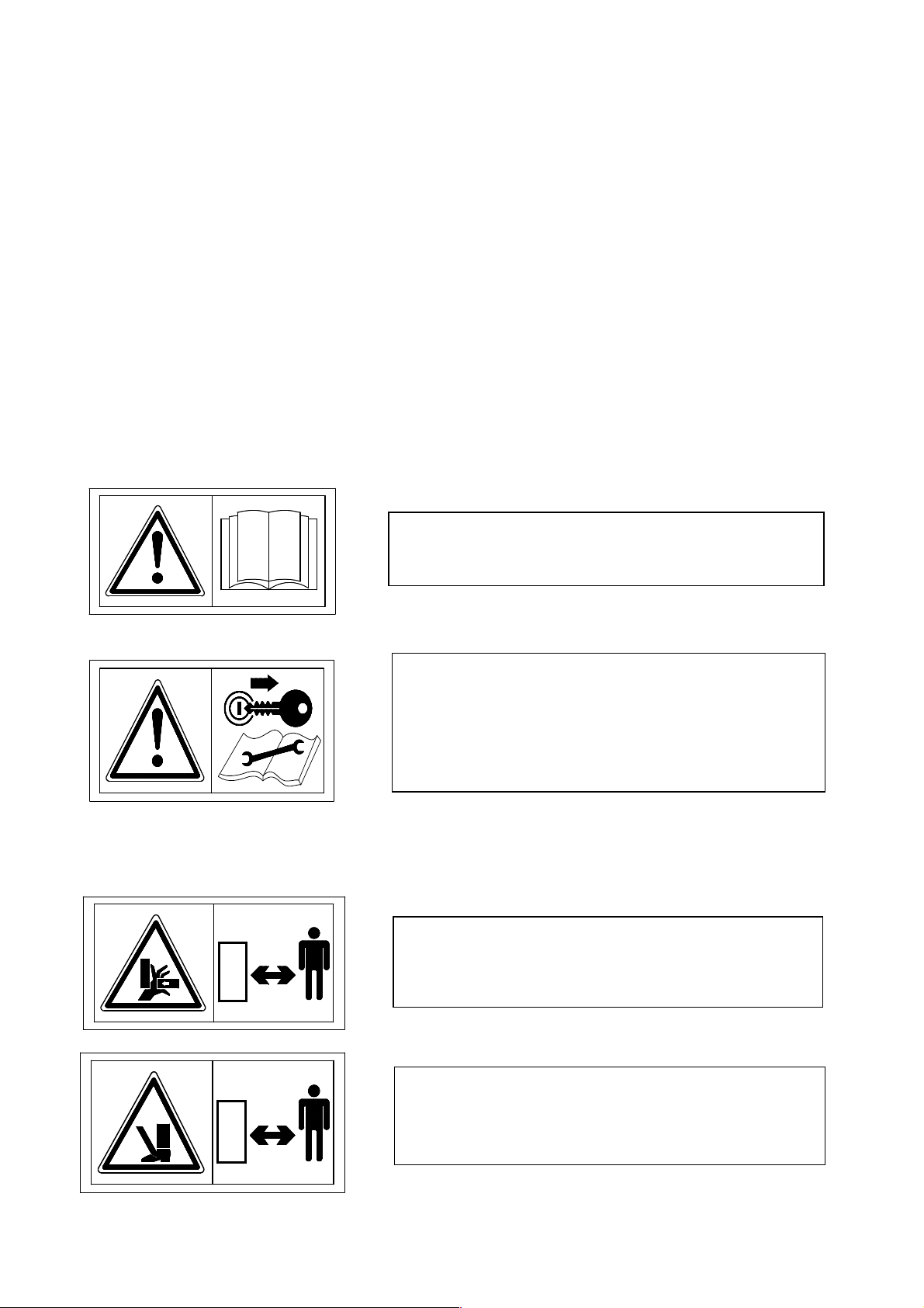
1) MEANING OF THE SIGNS AND SYMBOLS APPLIED
TO THE MACHINE AND/OR USED IN THIS MANUAL.
IMPORTANT
These signs and symbols give the operators information on how to make the best use
of the machine so as to prolong its life, avoid damage to the machine and to objects,
optimize work and, above all, on how to avoid injury to the operator and to
anyone who is within the operating range of the machine. Note: most of the signs
and symbols you will find here below are applied to the machine, but some may be
only in this manual, and they are there to indicate how to act or what must be done
during assembly, use, maintenance and/or repairs.
WARNING SIGNS AND SYMBOLS
1) Read the instruction manual before
starting any operations.
2) Before doing any checking, maintenance
and/or repair operations, stop in a suitable
place, turn off the tractor, apply the brake,
remove the ignition key and consult this
manual.
DANGER SIGNS AND SYMBOLS
3
3) Warns against the potential and serious
danger of crushing hands. Keep your distance.
4) Warns against the potential and serious
danger of injury to the feet. Keep your
distance.
SIGNS AND SYMBOLS OF INDICATIONS AND
RULES
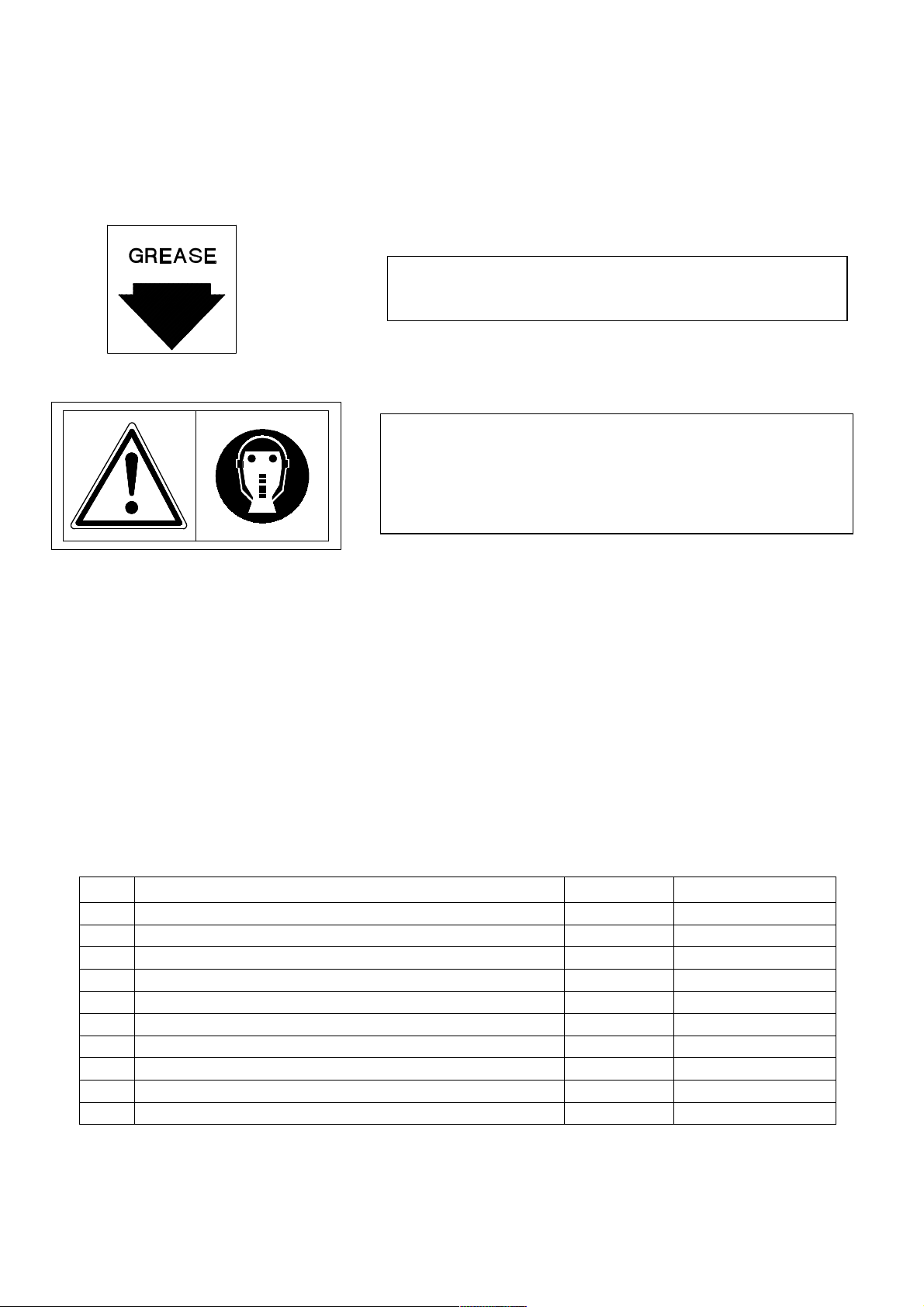
5) Indicates the points to be greased
6) Recommends that suitable protective equipment
and clothing be worn to prevent injury during the
stages of assembly, use, maintenance and/or
repairs.
Note: For the location of the signs and symbols on the machine, see p.5
1) LOCATION OF DECAL AND DEVICES FOR SAFETY, FOR THE
CONTROLS AND FOR IDENTIFICATION OF THE MACHINE AND THE
MANUFACTURER.
Pos.
DESCRIPTION
MACHINE & MANUFACTURER IDENTIF. PLATE
1
DECAL " FIRST OF ALL READ THE MANUAL"
2
DECAL " READ THE MANUAL BEFORE OPERATING"
3
SITREX LOGO DECAL (SMALL)
4
SITREX LOGO DECAL
5
MACHINE NAME DECAL
6
DECAL “DANGER OF INJURY TO HANDS” (SMALL)
7
GREASE POINTS DECAL
8
DECAL “DANGER OF INJURY TO HANDS”
9
DECAL “DANGER OF INJURY TO FEET”
10
Qty. Notes
1 See on the machine
1 See p. 3 step 1
1 See p. 3 step 2
1 See on the machine
1 See on the machine
1 See on the machine
3 See p. 3 step 3
10-11-12-13
3 See p. 3 step 3
2 See p. 3 step 4
See p. 4 step 5
4
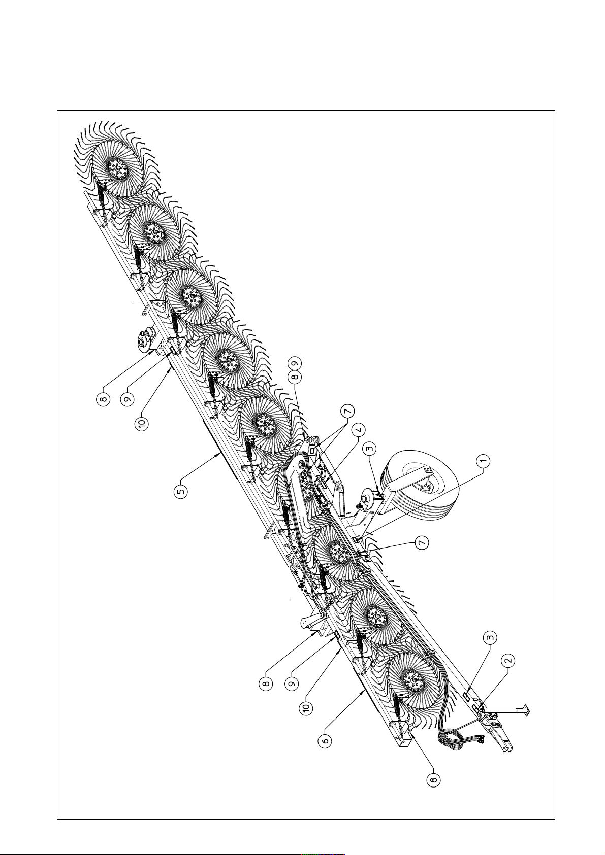
1) LOCATION OF DECAL AND DEVICES FOR SAFETY, FOR THE
CONTROLS AND FOR IDENTIFICATION OF THE MACHINE AND THE
MANUFACTURER.
5

2) GENERAL SUMMARY OF SAFETY AND ACCIDENT
PREVENTION INSTRUCTIONS.
Read all the instructions and rules carefully before using the machine. If you
have any doubts, contact the dealer, the distributor or the manufacturer. The
manufacturer disclaims all liability for non-compliance with the safety and
accident prevention instructions and rules.
1) Pay attention to the danger signs and symbols on the machine and in the manual.
2) Do not touch moving parts.
3) All work on the machine (including adjustments) must always be done with the
tractor stopped, the brake on and the engine turned off.
4) It is strictly prohibited to carry persons and/or objects on the machine and/or on the
tractor.
5) It is strictly prohibited for persons without a license, without the necessary
experience or who are not physically fit to drive the tractor with the machine
connected.
6) All safety and accident prevention measures prescribed in this manual must be
strictly observed.
7) Always evaluate whether the tractor to be used is suitable for the purpose, given
that even if the machine is the trailed type, it alters the tractor’s stability; therefore,
take all the necessary precautions for working in safety (take into consideration the
type of terrain, tire pressure, etc.).
8) Check that all safety devices for transport and working are in good condition and
functioning before operating the machine.
9) When driving on public roads, always observe the traffic rules and regulations of
the country where you are working.
10) Familiarize yourself with all the controls and the use of the machine before
starting to work.
11) Wear suitable clothing while using the machine. Do not wear clothing that is
loose or that could get caught in the moving parts.
12) Never leave the driver’s seat while the tractor is moving.
13) Always bear in mind that the road holding, steering and braking of the tractor are
significantly affected by the machine being trailed.
14) Turn off the engine, apply the brake and remove the key from the ignition before
attaching/detaching the machine to/from the tractor.
15) Replacement parts must meet the requirements defined by the manufacturer. Use
only original replacement parts.
16) The safety stickers must always be in good condition and clearly visible. They
should be kept clean and must be replaced if they become illegible (if necessary they
can be ordered like any other replacement part).
Note: this machine is not approved for transport on public roads, therefore
anyone who wishes to do so must have the machine approved according to the
local regulations in force.
6
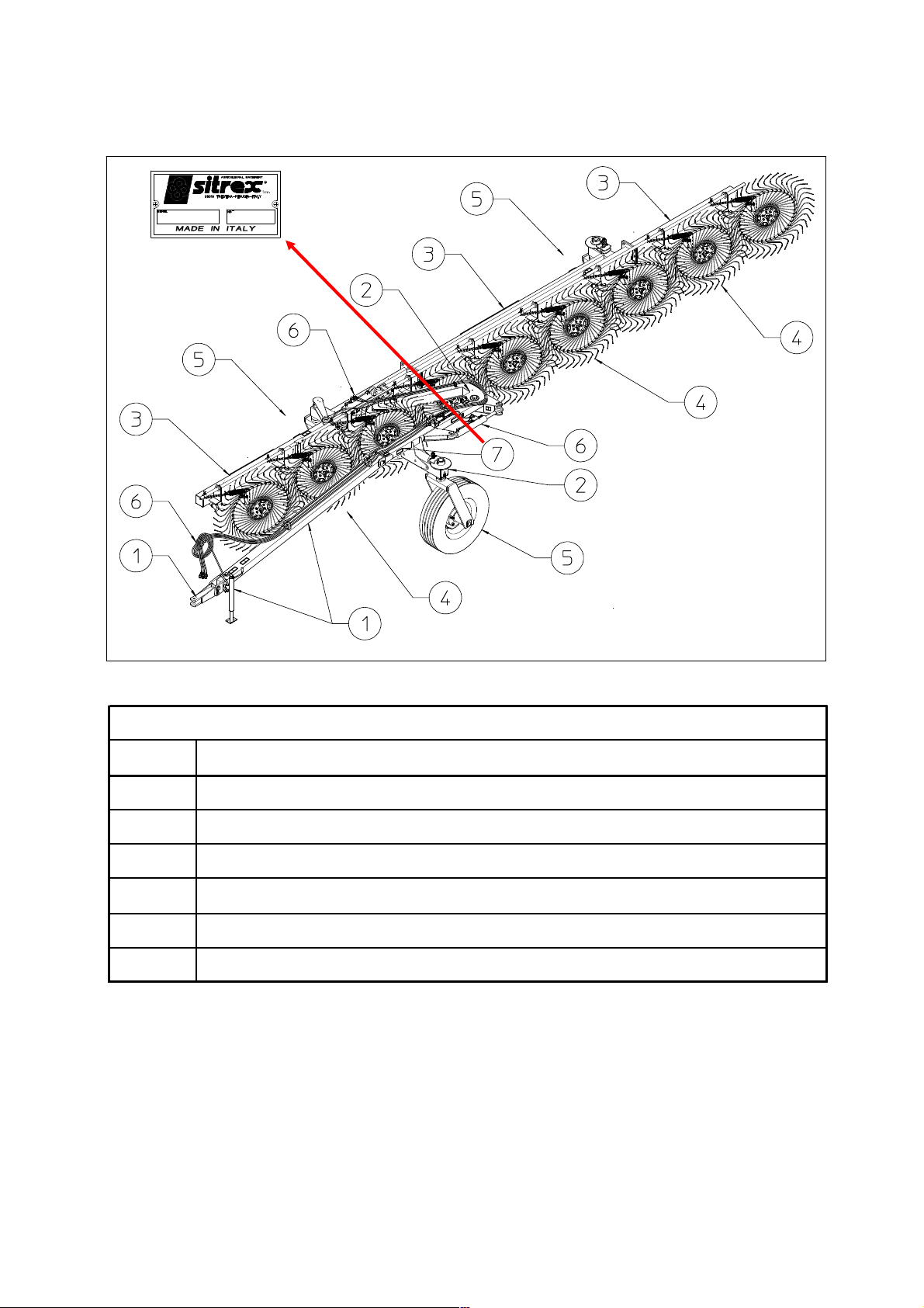
3) PRODUCT IDENTIFICATION
1
2
3
4
5
6
7
DRAWBAR AND ACCESORIES FOR TRANSPORT
FRAME
RAKE SECTIONS
RAKE WHEELS AND ACCESORIES
WHEELS AND TRAILER ACCESSORIES
HYDRAULIC SYSTEM
IDENTIFICATION PLATE
MAIN PARTS
7
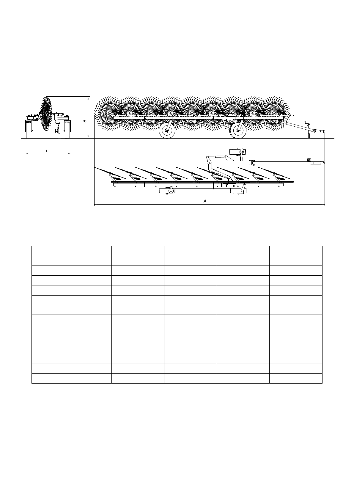
3) TECHNICAL SPECIFICATIONS
MODELS TR/6-S TR/8-S TR/7-S TR/9-S
Weight
Overall length (A)
Transport height (B)
Transport width (C)
710 Kg / 1565 lbs 780 Kg / 1720 lbs 735 Kg /1620 lbs 815 Kg /1795 lbs
7.1 m / 23' 8.75 m / 26'3" 7.95 m / 23'4" 9.65 m / 31'6"
1.7 m / 67" 1.7 m / 67" 1.7 m / 67" 1.7 m / 67"
1.95 m / 77" 1.95 m / 77" 1.95 m / 77" 1.95 m / 77"
Number of rake
wheels
6 8 7 9
Number of tines on
each rake wheel
Tines diam.
Wheel diam.
Raking working width
Working speed
22 kmh / 14 mph 22 kmh / 14 mph 22 kmh / 14 mph 22 kmh / 14 mph
HP required min.
The data are approximate. The manufacturer reserves the right to change them at any time without notice.
40 40 40 40
7mm/0.3" 7mm/0.3" 7mm/0.3" 7mm/0.3"
1.4 m / 55" 1.4 m / 55" 1.4 m / 55" 1.4 m / 55"
4 m / 13'2" 5 m / 16'5" 4.5 m / 14'9" 5.5 m / 18'
30 Hp / 26 Kw 30 Hp / 26 Kw 30 Hp / 26 Kw 30 Hp / 26 Kw
8
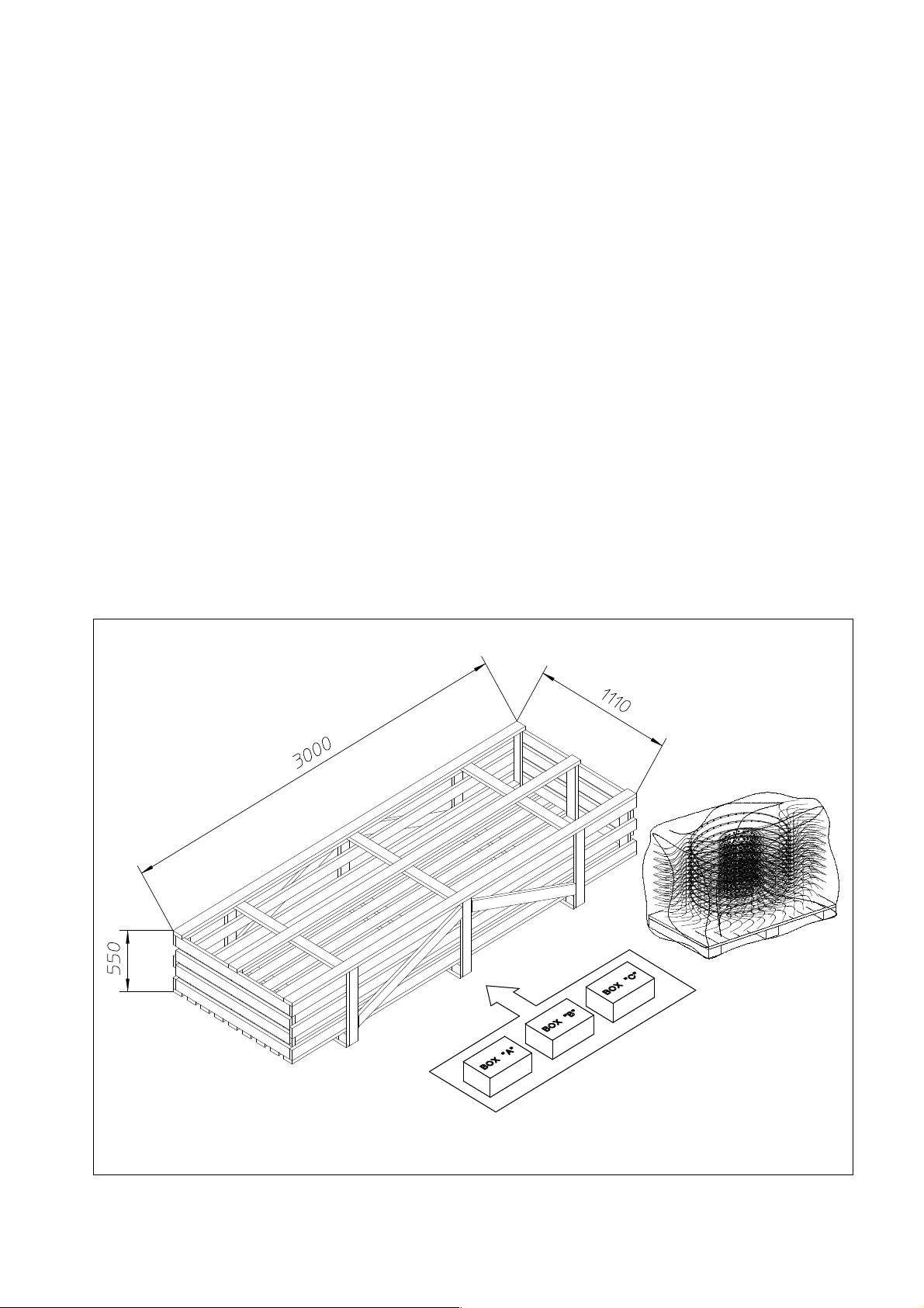
4) DELIVERY, CHECKING AND ASSEMBLY OF THE MACHINE
Delivery and unpacking.
The machine is delivered partially assembled in one crate and one pallet containing
the rake wheels. In the crate there are the parts to be assembled and three cardboard
boxes (marked “A”, “B”, “C” ) which contain the accessories for assembly (nuts and
bolts, couplings, pins, etc.).
On the pallet there are 9 (or 8/or 7/or 6) RH rake wheels.
All components are checked before being shipped by the manufacturer. Upon receipt
of the machine, check that the crates are in good condition and that the contents have
not been damaged during transport. If there is any damage and/or irregularities, notify
your dealer immediately.
Note: the packing materials consist of wood, plastic film, cardboard and steel
supports, and must be disposed in accordance with your local laws.
Handle the crates and pallets using forklifts that are suitable both for lifting the
weight indicated and for giving stability to the crates and pallets in consideration of
their size and shape.
9

Assembly Instructions
Examples of general measurements for identifying assembly accessories according to
type.
To make it easier to identify the assembly accessories (nuts, bolts, washers, pins, etc.)
on the basis of the general dimensions and the type, we provide a diagram that shows
you the accessory parts to which the measurements refer as given in the various steps
of assembly.
The drawings are schematic and do not always faithfully reproduce the accessories,
but they will be of help in identifying them correctly.
Note: the accurate measurements are those given in mm; those given in inches are
rounded off, and for threads the size in inches is given only as an aid, as it does not
accurately describe the thread.
You can see the following examples:
Box “A”: shows springs that are will be identified by the wire diameter, the outside
diameter and the length, thus in this case ø3-ø18x110 (ø0.12”-ø0.71”x4.33”)
Box “B”: shows handles, spring pins, split pins, etc. that will be identified by the
diameter of the shank and the length, thus in this case ø8 x 50 (ø0.12” x 1.97”)
Box “C”: shows shims, bushings, spacers and washers in general that will be
identified by the inside diameter, the outside diameter and the length and/or the
thickness (for washers), thus in this case ø18-ø35 x 30 (ø0.71”-ø1.38” x 1.18”) or for
washers ø18-ø35 x 3 (ø0.71”-ø1.38” x 0.12”).
Box “D”: shows retaining rings for internal housings/bores that will be identified by
the diameter of the bore preceded by an I, thus in this case I35-1.38”, and for external
shafts that will be identified by the diameter of the pin preceded by an E, thus in this
case E35-1.38”.
Box “E”: shows pins, bolts, etc. that will be identified by the outside diameter (thread
diameter for bolts) and the length, thus in this case ø20 x 70 (ø0.78” x 2.76”) or for
bolts M20 x 70 (0.78” x 2.76”).
Box “F”: shows nuts and grease nipples that will be identified by the thread diameter,
thus in this case M10 (0.39”).
Box “G”: shows R-clips that will be identified by the diameter of the shank, thus in
this case ø3 (ø0.12”).
10

Assembly Instructions
Examples of general measurements for identifying accessories for
assembly according to type.
For tightening torques, see the table below (the class of the material is normally
stamped on the head of the bolts).
11
ASSEMBLY SEQUENCE
The machine must be assembled in a suitable area, done by qualified personnel
equipped with the proper clothing, protective equipment and tools necessary for the job.
Only authorized persons should be in the assembly area.
Always use great caution because the assembly steps are dangerous.
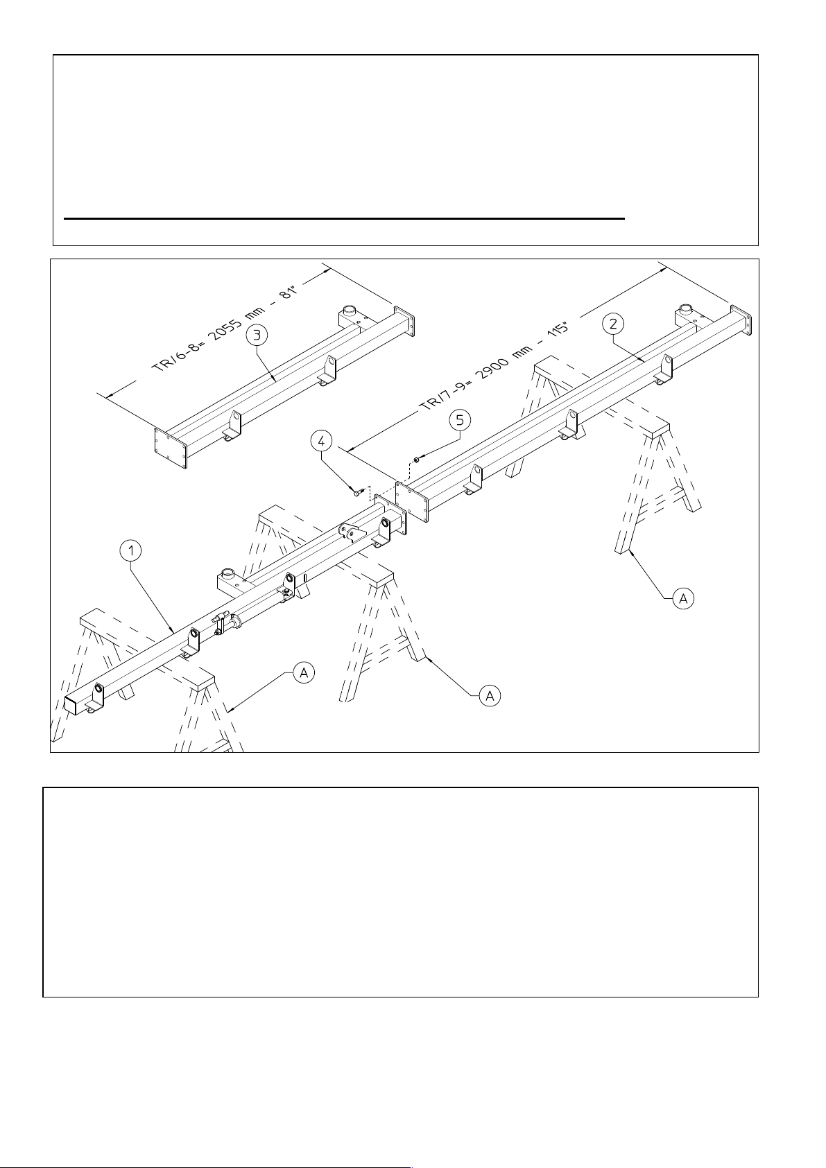
1) DANGER
Place the section 1 on the supports A.
Attach section 1 to section 2 (TR/7-9) or 3 (TR/6-8) using bolts 4 and nuts 5.
Place the section 2 (or 3) on support A.
In this step, you will use:
Item 4: 8 bolts M16x45 (0.63”x1.77”)
Item 5: 8 nuts M16 (0.63”)
12
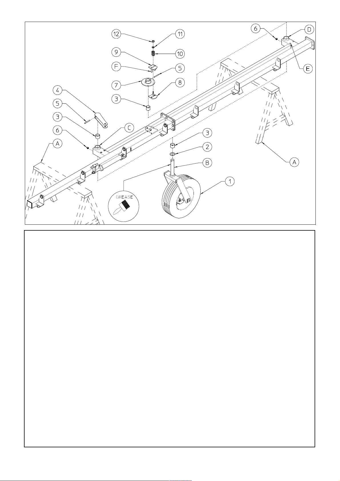
2) DANGER
Before attaching the wheel units 1, brush pin B and spring pins 5 with grease.
Insert the nylon bushings 3 into the proper seats C-D. Place spacer 2 on the pins B of the
wheel units 1. Insert the wheel units 1 into the proper seat C. Attach the lever 4 into the pins B
of the wheel units 1 using the spring pins 5. Attach the grease nipples 6 to the proper seat C.
Insert the wheel units 1 into the proper seat D. Attach the flange 7 into the pins B of the wheel
units 1 using the spring pins 5. Attach the plate with bolt 8 underneath flange 7. Attach the
brake plate 9 over flange 7, inserting the brake plate pins F into the holes in the plate with bolt
8 and into holes E in the sections. Place the spring 10, and washer 11 over the plate with bolt 8
and put nut 12 on the bolt.
Note: the more spring 10 is compressed by tightening nut 12, the more the turning of the
wheel is braked, therefore check that it is adjusted properly when the machine is to be
operated . Attach the grease nipples 6 to the proper seat D.
In this step, you will use:
Item 2: 2 spacers ø50-76x5 (1.97”x3”)
Item 3: 4 nylon bushings ø50-60x50 (ø1.97”-2.36x1.97”)
Item 5: 2 spring pins ø10x80 (0.4”x3.15”)
Item 6: 2 grease nipples M8 (0.31”)
Item 10: 2 springs ø5-30x45 (0.20”-1.18”x1.77”)
Item 11: 2 washers ø12-36x4 (ø0.47”-1.42x0.16”)
Item 12: 2 nuts M12 (0.47”)
13
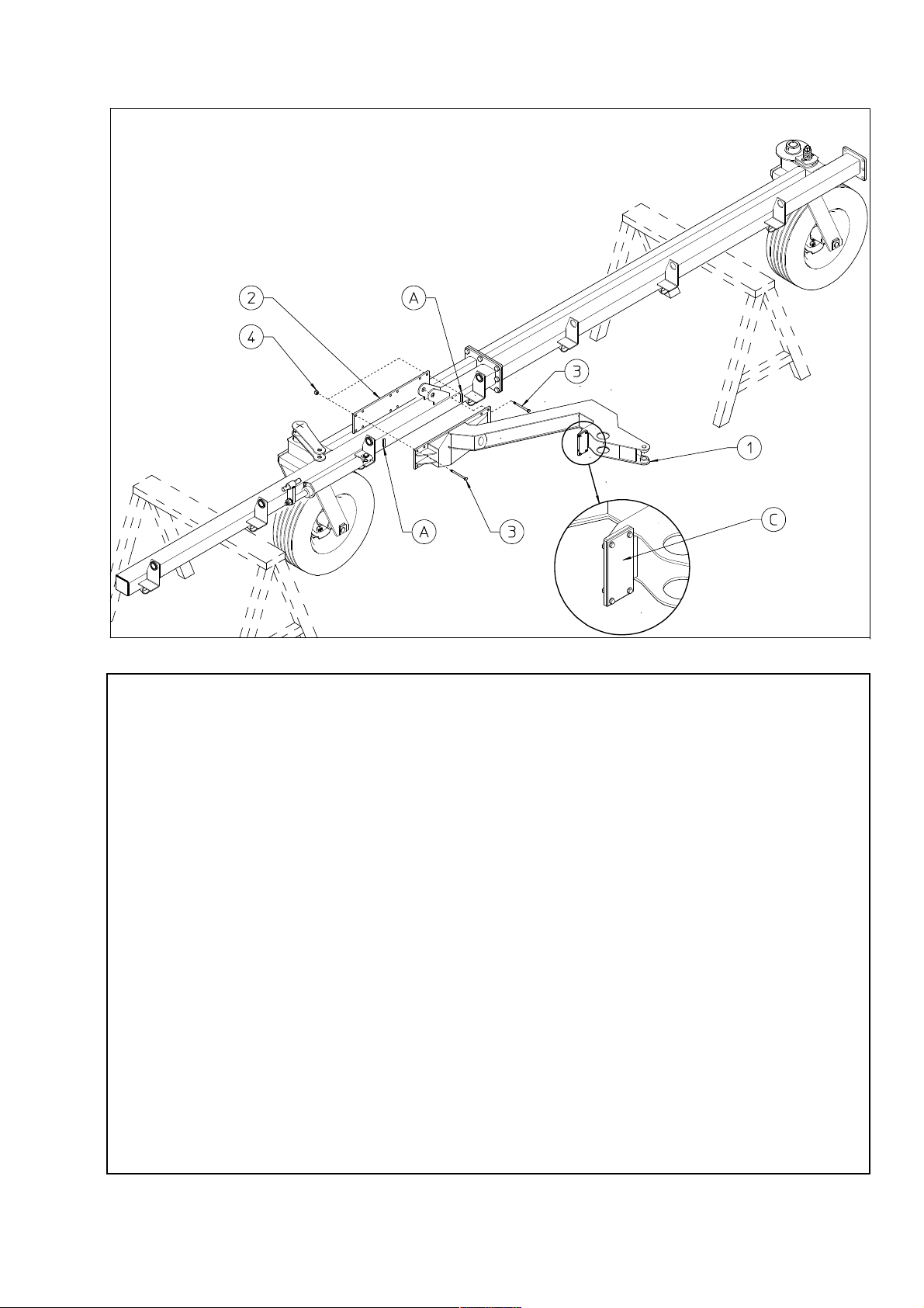
3) DANGER
Carry out this operation very carefully and with suitable lifting equipment because
the support 1 is heavy and bulky.
First of all make sure that the manufacturer has installed the rubber bumper B on
support 1.
Support 1 must be positioned between the retainers A.
Attach the support 1 to sections by means of the counterplate 2, bolts 3 and nuts 4.
In this step, you will use:
Item 6: 12 bolts M14x140 (0.55”x5.51”)
Item 7: 12 nuts M14 (0.55”)
14
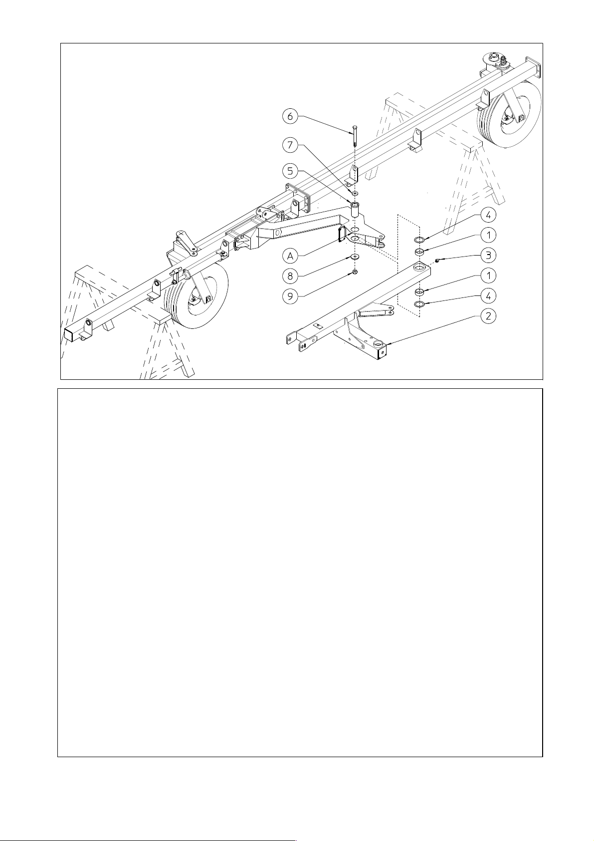
4) DANGER
Attach the nylon bushings 1 to the proper seats. Attach the grease nipple 3 to the
proper seat.
Connect support 2 to seat A on the arm using pin 5, shims 4, bolt 6, washers 7-8
and nut 9.
In this step, you will use:
Item 1: 2 nylon bushings ø75-85x30 (ø2.95”-3.35”x1.18”)
Item 3: 1 grease nipple M8 (0.31”)
Item 4: 2 shims ø75-100x1 (ø2.95”-3.94”x0.04”)
Item 5: 1 pin ø 75x115 (2.95” x 4.53”)
Item 6: 1 bolt M24x165 (0.94”x6.5”)
Item 7: 1 washer ø25-64x10 (ø1”-2.52”x0.4”)
Item 8: 1 washer ø25-90x10 (ø1”-3.54”x0.4”)
Item 9: 1 nut M24 (0.94”)
15
 Loading...