

Page 1
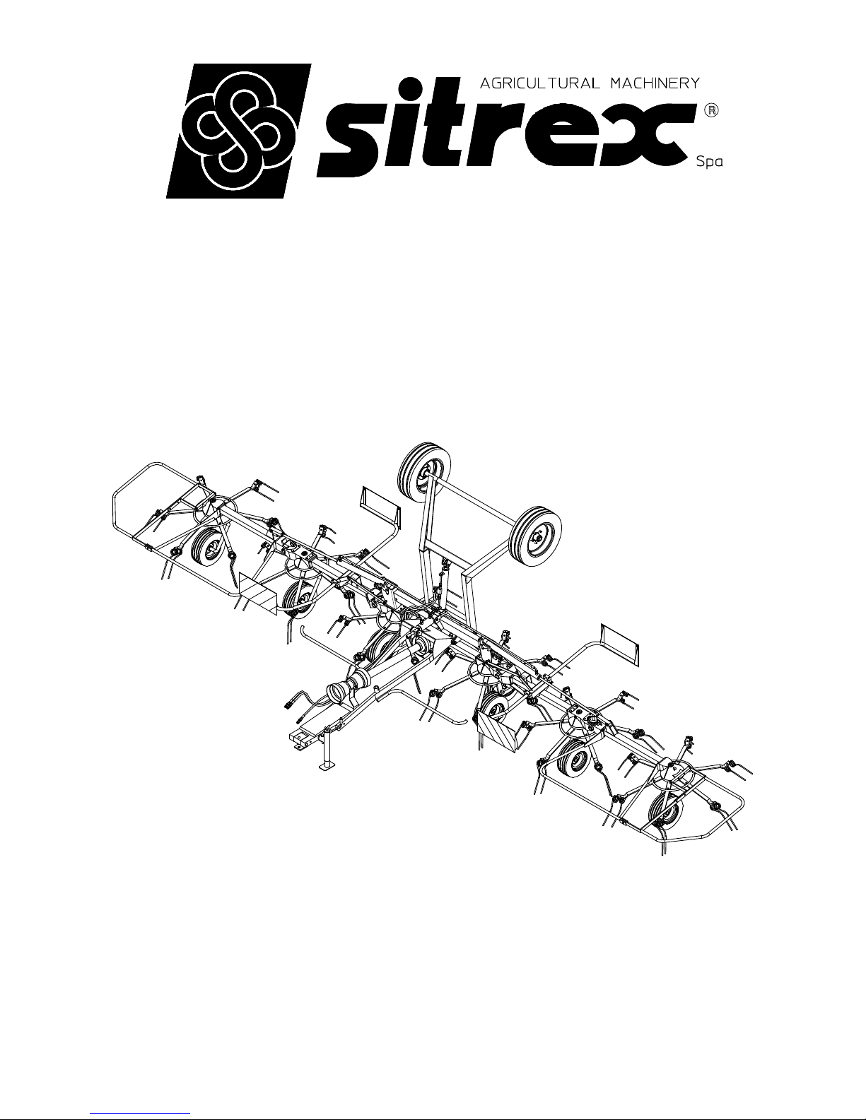
ASSEMBLY, USE AND MAINTENANCE
ST 780 H
ROTARY TEDDER
05/2006
Page 2

1
WARRANTY
SITREX spa warrants new SITREX machinery at the time of delivery to the original purchaser
to be free from defects in material and workmanship if properly set up and operated in
accordance with this Operator’s Manual.
SITREX undertakes to repair or replace free of charge any defective part which should be
returned by the purchaser (freight prepaid) and found to be defective by inspection authorized
by SITREX during the warranty period.
This warranty will be valid for 12 (twelve) months from the delivery of goods to the original
purchaser .
In case the customer is not in a position to return the defective part to the manufacturer , the
manufacturer cannot be held responsible for any cost due for repair or replacement of any part
of the machine , he will only supply the part(s) required for the repair and/or replacement.
The warranty is null and void when it is evident that the machine has been improperly used or
however repaired without authorization.
SITREX undertackes no responsability for any obligation or agreement reached by any
SITREX employers,agents or dealers, which are not in compliance whit the above warranty .
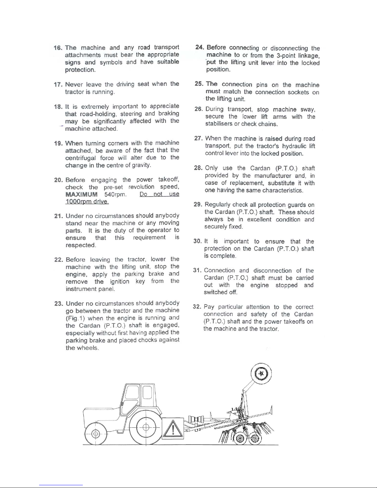
The manifacturer cannot be held responsible for the consequent damages. This warranty
substitutes any other warranthy , espress or implied , and any other manifacturer’s obligation.
CHAPTHER
1) GUIDE TO THE SIGNS
2) General summary of safety and accident-prevention instrutions
3) PRODUCT IDENTIFICATION
4) DELIVERY AND ASSEMBLY
5) ADJUSTMENT, PREPARATION AND USE
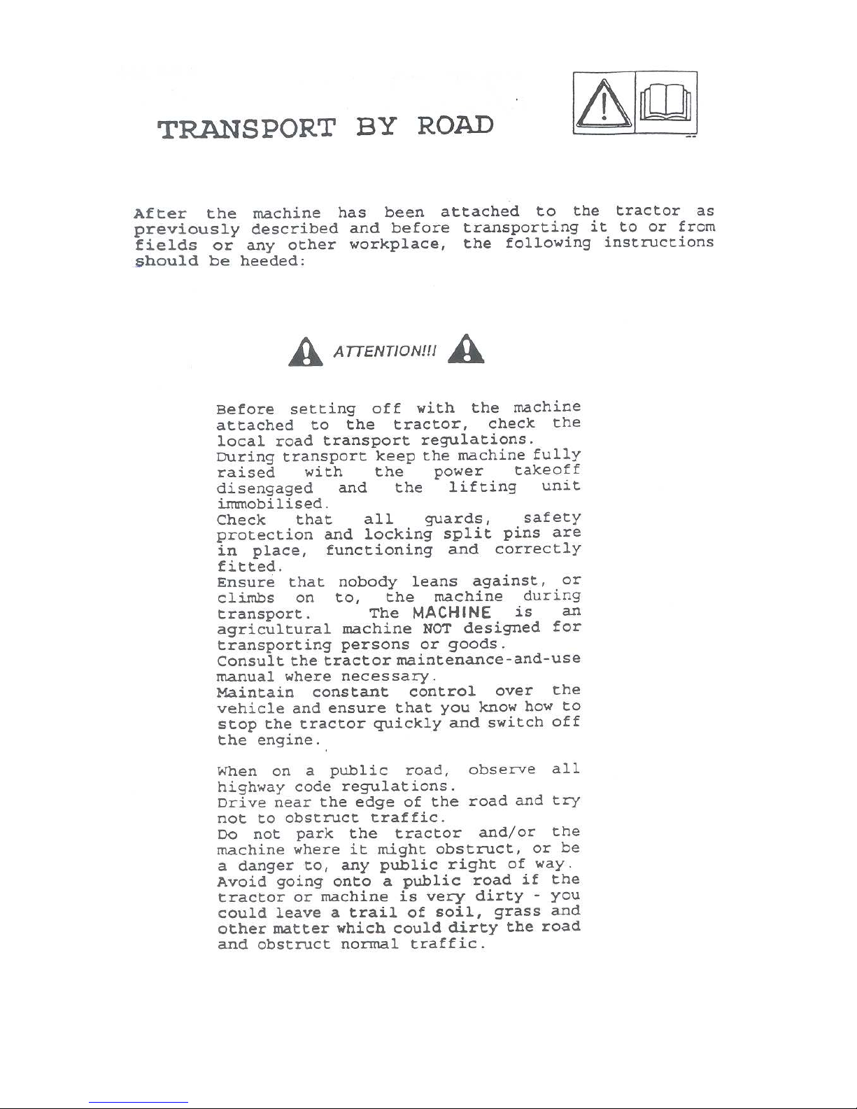
6) TRANSPORT BY ROAD
7) USE IN THE FIELD
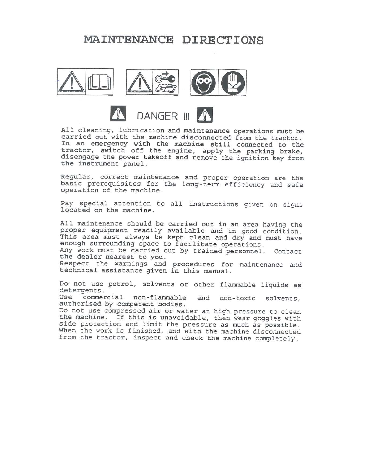
8) MAINTENANCE
Page 3
2
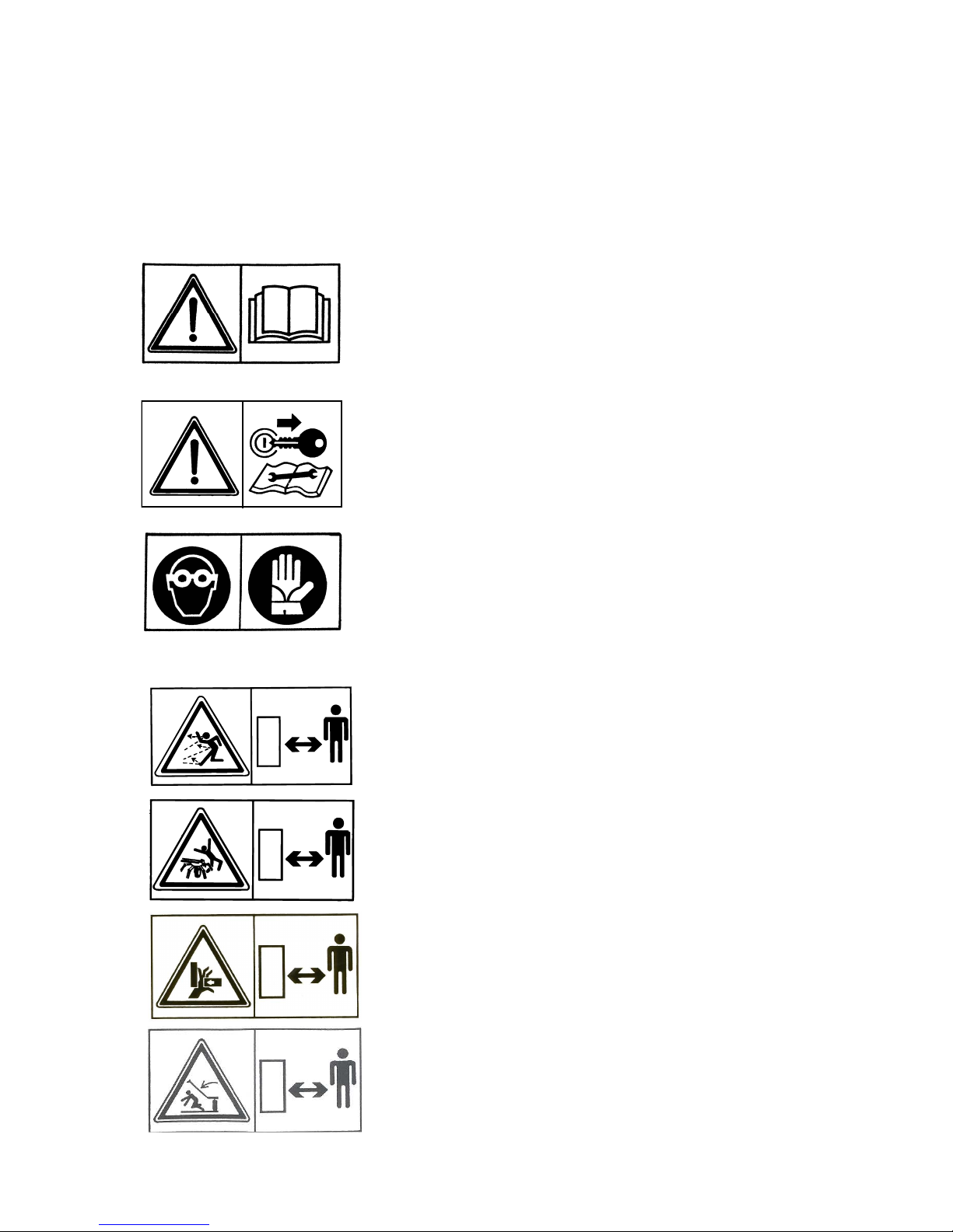
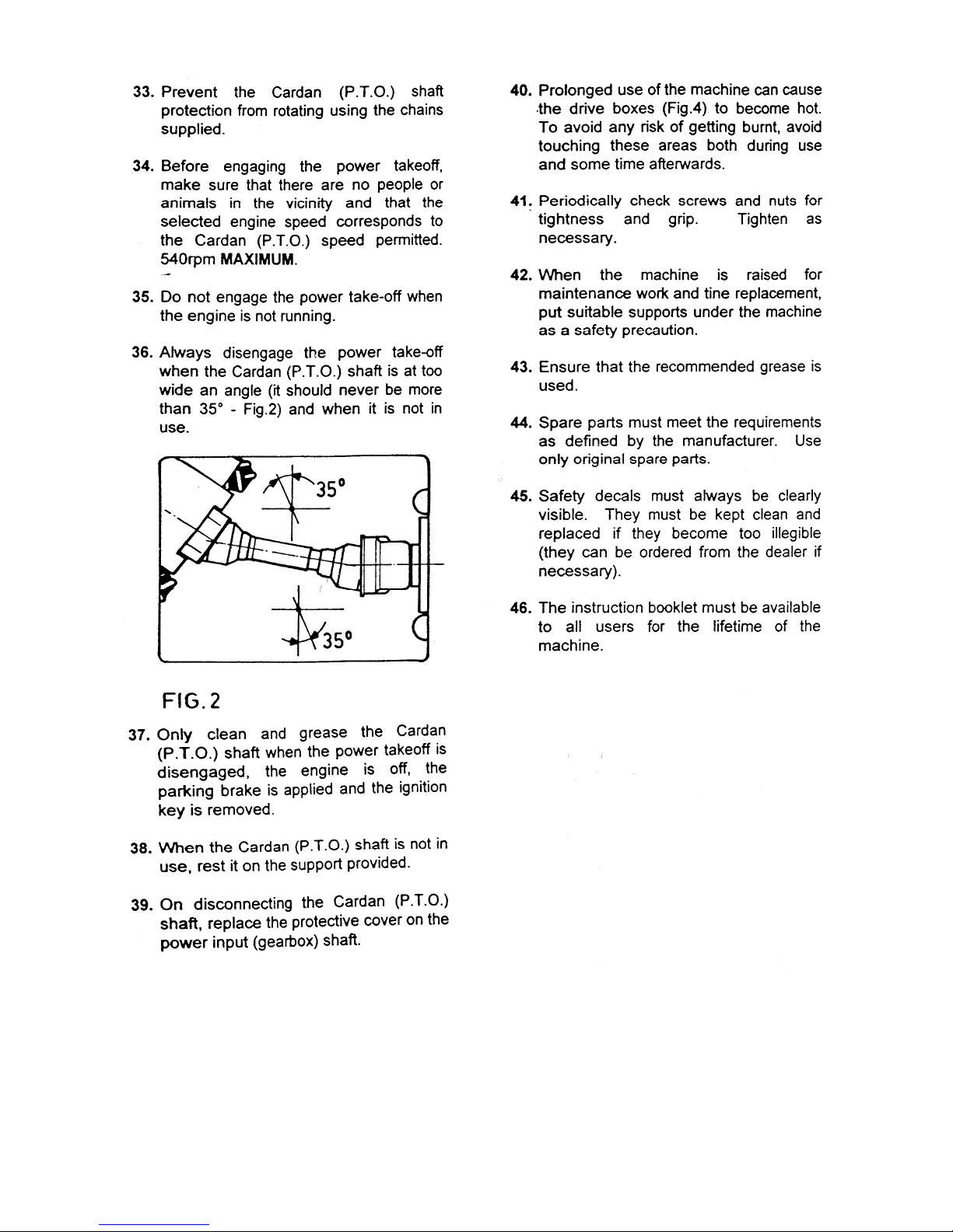
GUIDE TO THE SIGNS AND SYMBOLS USED THIS
MANUAL AND THEIR LOCATION ON THE MACHINE
IMPORTANT
These signs and symbols give information to the operator on how to make the best use of the machine so as to prolong
life, avoid damage, optimise work and, above all, to avoid injury to the operator and anyone within range of the
machine.
WARNING SIGNS
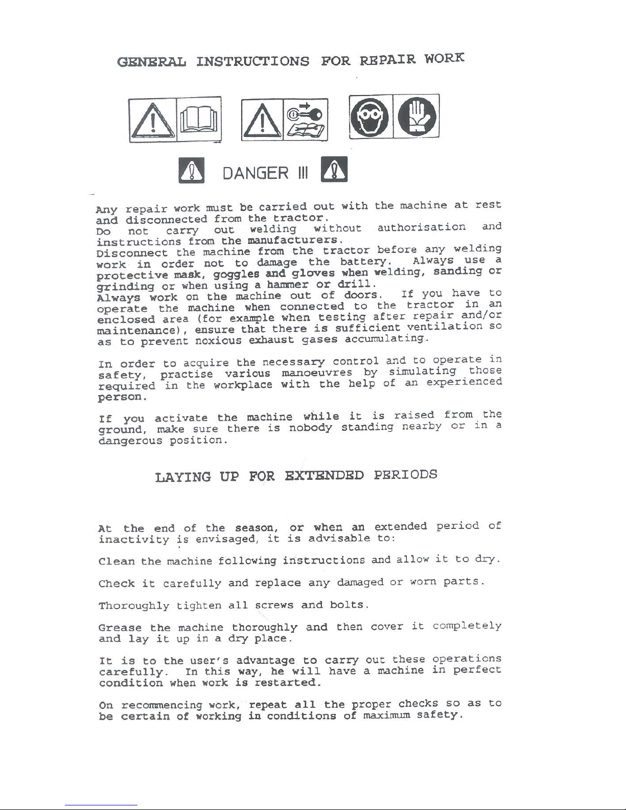
1) Before beginning operations, read the instruction manual carefully.
2) Before doing any maintenance or repair work, stop the machine at a suitable
spot. Turn off the tractor motor, apply the brake, remove the key from the
ignition and consult this manual.
3) This is a warning to use proper accident protection when carrying out
maintenance and repairs
DANGER SIGNS
4) Risk of possible ejection of blunt objects. Keep a safe distance from
the machine
5) Indicates that anyone coming within range of the moving tine arms will
be seriously injured.
Keep a safe distance from the machine.
6) Indicates that there is a risk of crushing your hands. Keep your distance.
7) Indicates danger caused by accidental fall of suspended arms. Keep safe
distance.
Page 4
3
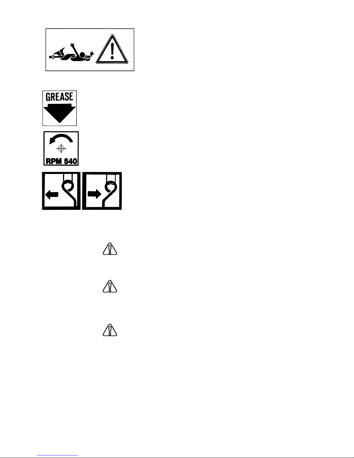
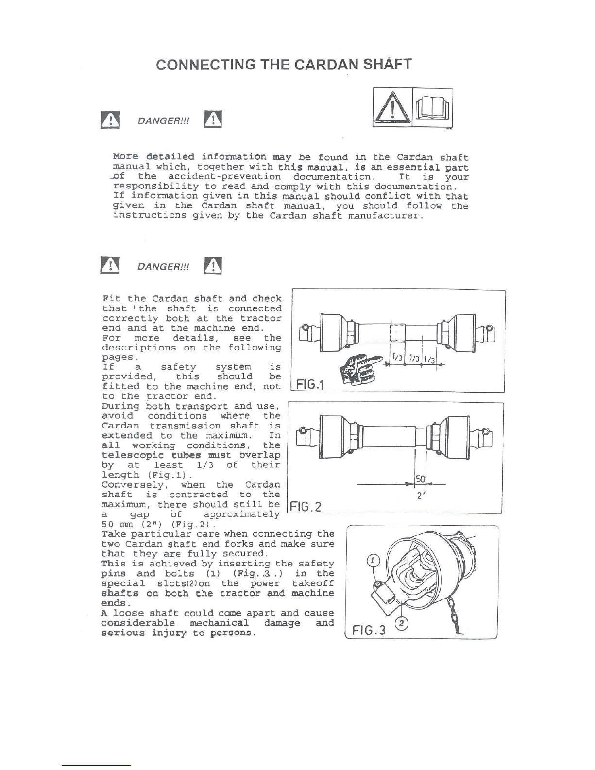
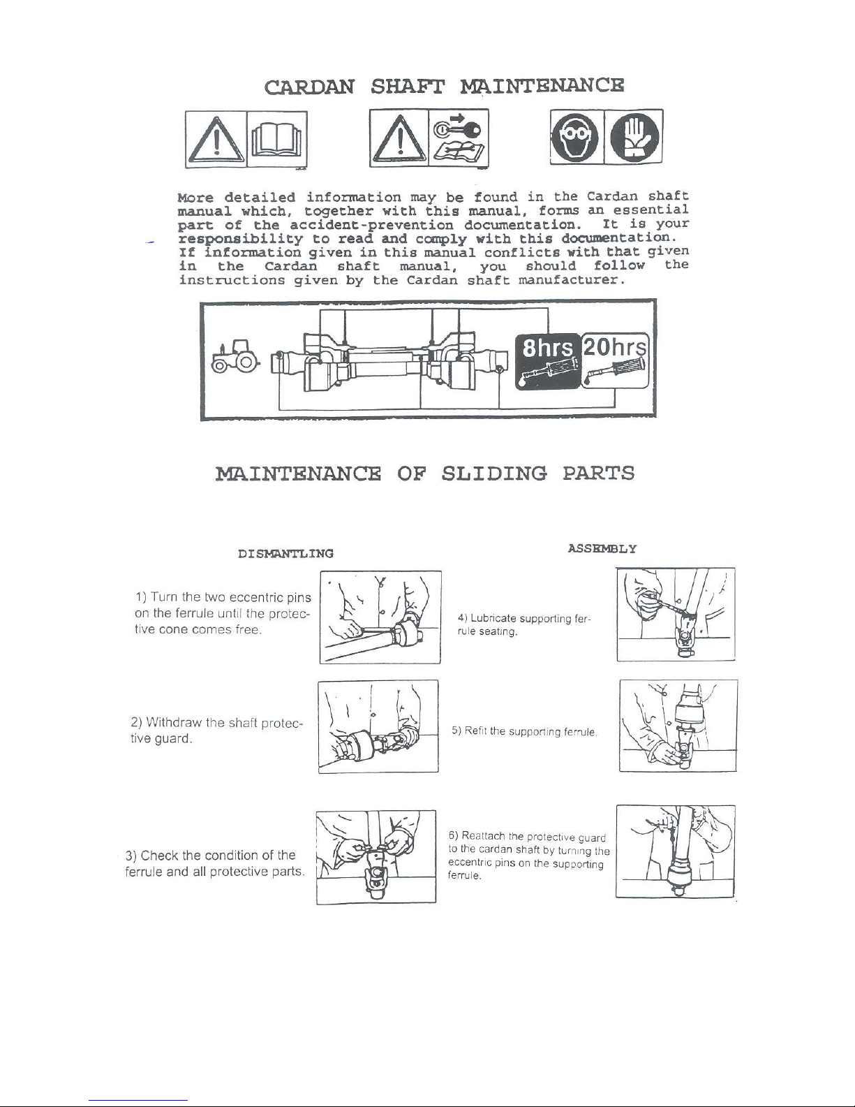
8) Indicates that it is dangerous to touch the cardan (P.T.O.) shaft.
For all the other information regarding the cardan shaft, see the use and
maintenance booklet specifically for the cardan shaft which, together with
this manual, makes up the documentation on safety, use and maintenance of
the machine.
INDICATION SIGNS
9) Indicates a greasing point .
10) Shows the direction of rotation of the power takeoff and the maximum number revolutions.
11) Indicates position of the tines on the rotors and their direction of rotation.
MANUAL SIGNS.
Indicates an impending dangerous situation which, if not avoided, will cause
death or severe personal injury.
Indicates a potentially dangerous situation which, if not avoided, could cause
death or severe personal injury, including dangers which are present when
protection is removed.
indicates a potentially dangerous situation which, if not avoided, can provoke
less severe or minor injuries.
DANGER
ATTENTION
CAUTION
Page 5
4
Page 6
5
Page 7
6
Page 8
7
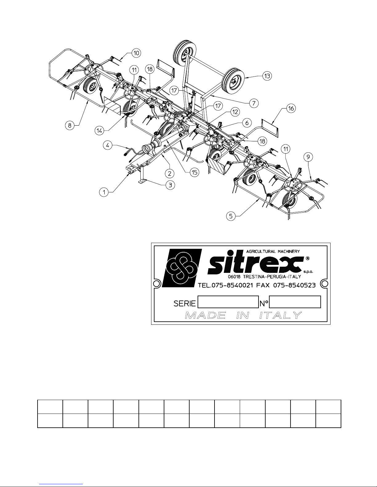
PRODUCT IDENTIFICATION
MAIN PARTS
1) BRACKET
2) DRAWBAR
3) PARKING STAND
4) HYDRAULIC KIT
5) L.H. GUARD
6) RATCHET
7) AXLE
8) R.H. GUARD
9) TINE ARM
10) TINE
11) GEARBOX
12) FRAME
13) TRANSPORT TYRES IDENTIFICATION PLATE
14) WORKING TYRES
15) CARDAN SHAFT
16) LIGHTING BRACKET
17) CYLINDER
18) CYLINDER
Rotors Arms for
Rotor
RPM
Rotors
RPM
Tractors
Tyres
Working
M
aximum
Width
Transport
Width
Working
Width
Working
Width DIN
Power
Required
O
perating
Speed
WEIGHT
6 6 130 350-450 16X6.50 8,05 Mt 3 Mt 7,8 Mt 7,5 Mt HP 70 16 Kmh
Kg 1120
max 540 8PLY 26’ 5” 10’ 25’ 7” 24’ 7” KW 50 10 MPH
lbs 2470
Page 9
8
DELIVERY AND ASSEMBLY
Checking the machine on delivery
All parts are carefully checked before dispatch or delivery.
On receiving the machine, ensure that it has not been damaged during transport. If damage has
occurred, contact the dealer concerned.
Details of packing are given below.
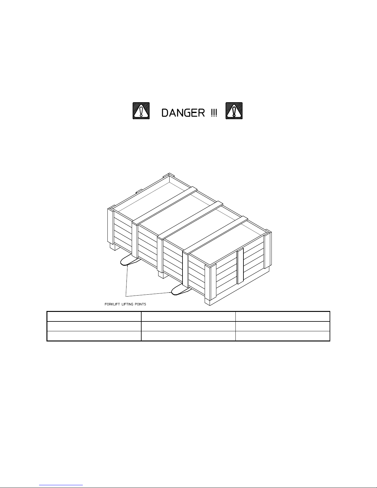
UNPACKING THE MACHINE
Lift the machine using a forklift truck, crane or other suitable equipment of sufficient capacity after
first checking the weight of the configurations in the table given below.
Check the stability and positioning of the load on the forklift truck forks or crane hook.
Keep the load as low as possible during movement for maximum stability and to ensure that the
operator has maximum visibility.
If a forklift truck is used, ensure that the forks are positioned as wide apart as possible.
WEIGHT PACKING WEIGHT
KG 1250 1120
LBS 2750 2470
NOTE:
1) The packing consists mainly of wood, which should be disposed of according to the laws
in force in the country where the machine is used.
The plastic film should also be disposed of according to the laws in force in the country
where the machine is used.
2) When storing, it is permissible to stack 2-3 crates on top of each other. Make sure that
they are perfectly aligned cortically.
3) In the event of further transport, ensure that the machine when on the transporting
vehicle.
Page 10
9
Assembly instructions
Assembly is highly dangerous and must be carried out in strict accordance with the following instructions.
We recommend that qualified personnel perform assembly. We also recommend that assembly be carried out
in a flat, solid surface, open area with no people (particularly children) nearby who could be severely injured
if they were to touch or move any parts of the machine.
Assemblers must provide suitable lifting mechanisms and supports for stabilizing the partially assembled
units, so as to prevent them from falling and causing damage or injury. The steps for assembly are illustrated
in following. Depending on the experience of the assemblers and the tools available, it is not necessary that
the instructions be followed in the exact order given here, but the safety precautions described above must
always be followed carefully and scrupulously.
Assembly sequence:
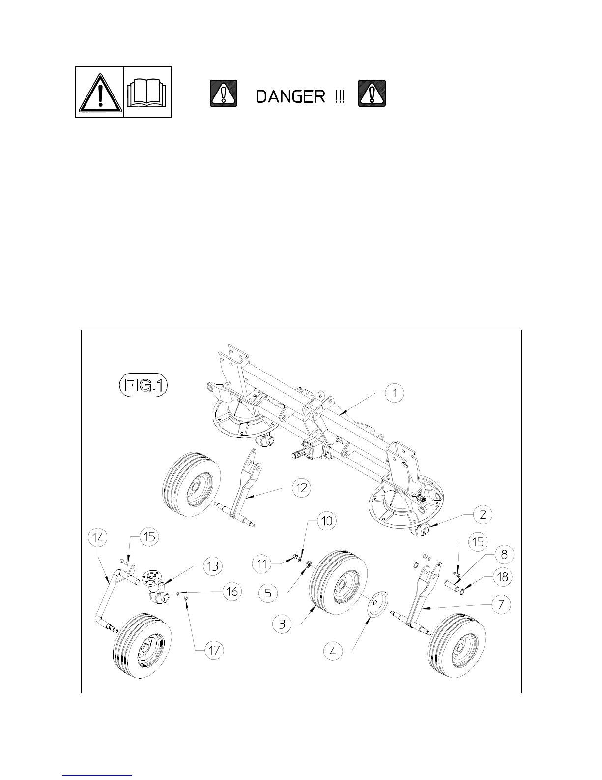
Fig. 1 - Place the rotor axle (1) in a stable position and then mount the tyres support (6). Use the pivot (8)
and the Seeger circlips (18) to mount support (7) and (12) on to the support so they are facing in the direction
shown in the figure. Use the washer (10) and nut (11) to assemble the wheels with their guards (4) and (5) on
to the tandems. Make sure that, when the wheel brackets (14) are mounted on to the supports (13), the
bracket plate matches the plate divided into sectors for the various supports. Use the screw (15), the nut
(17) and the washer (16) to fasten the wheel bracket into position..
Page 11
10
The wheels should face in the direction shown in the drawing.
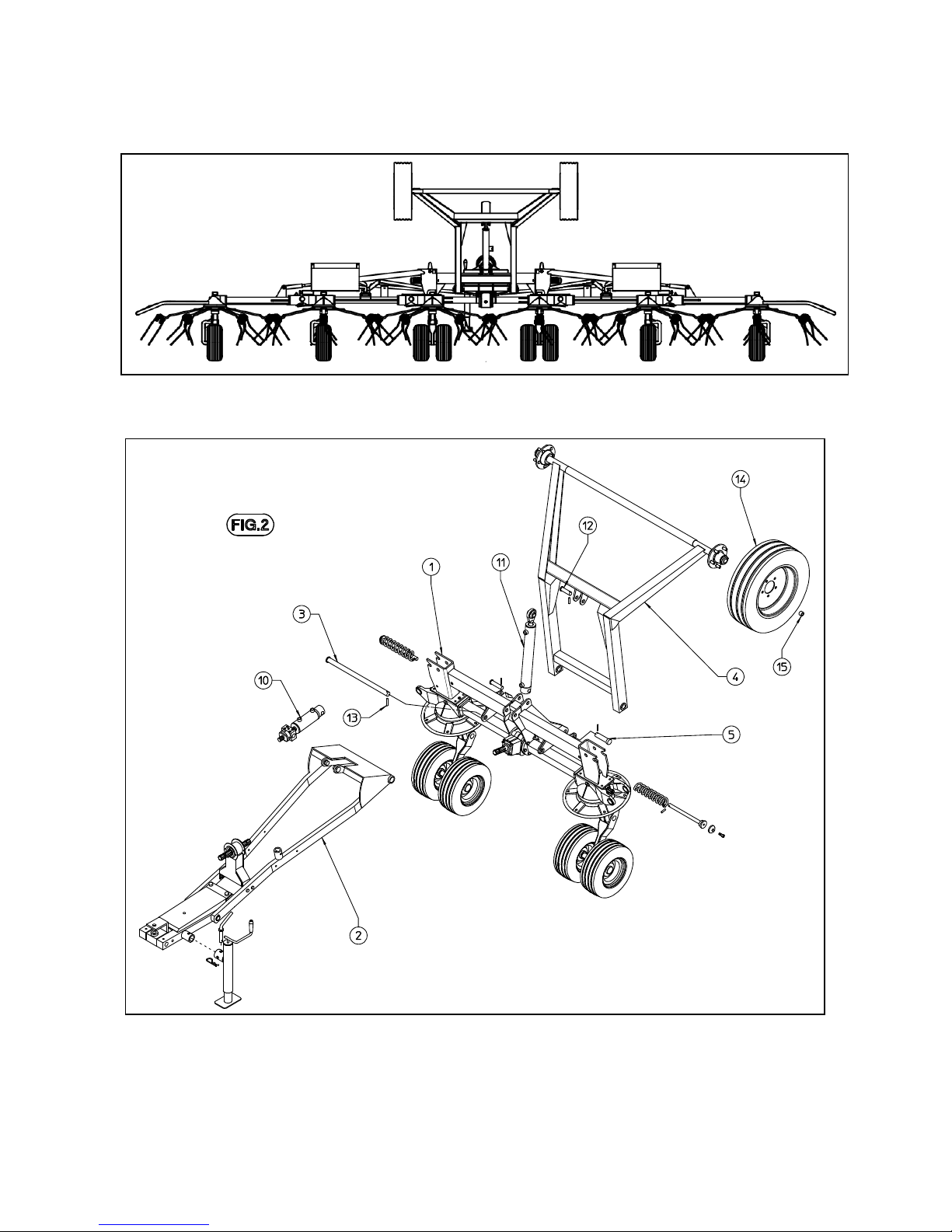
Fig. 2 - Use the pivot (3) and the elastic pin (13) to assemble the rotor group. Now assemble the transport
axle with the pivots (5). Use the grommet nuts (15) to fasten the wheels on to the rear axle.
After assembling the front drawbar and rear axle, mount the master cylinders (10) and (11). Use the two
pivots to fasten the axle cylinder, whereas the drawbar cylinder has first to be screwed on to the support
already assembled on the drawbar, and then the rear pivot is inserted.
Fasten the screwing block plate over the cylinder screw, as shown in the photo.
Page 12
11
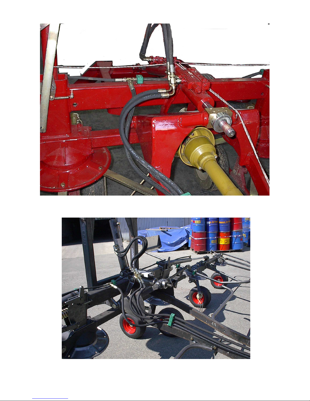
Assemble the oleodynamic system so that the tubes are arranged as shown in the following photo.
Pipes should be released in this phase (the hose clamps must not be tightened ). After connecting machine to
tractor, lift the machine, place hoses so that they do not force and then tighten hose-clamps.
Page 13
12
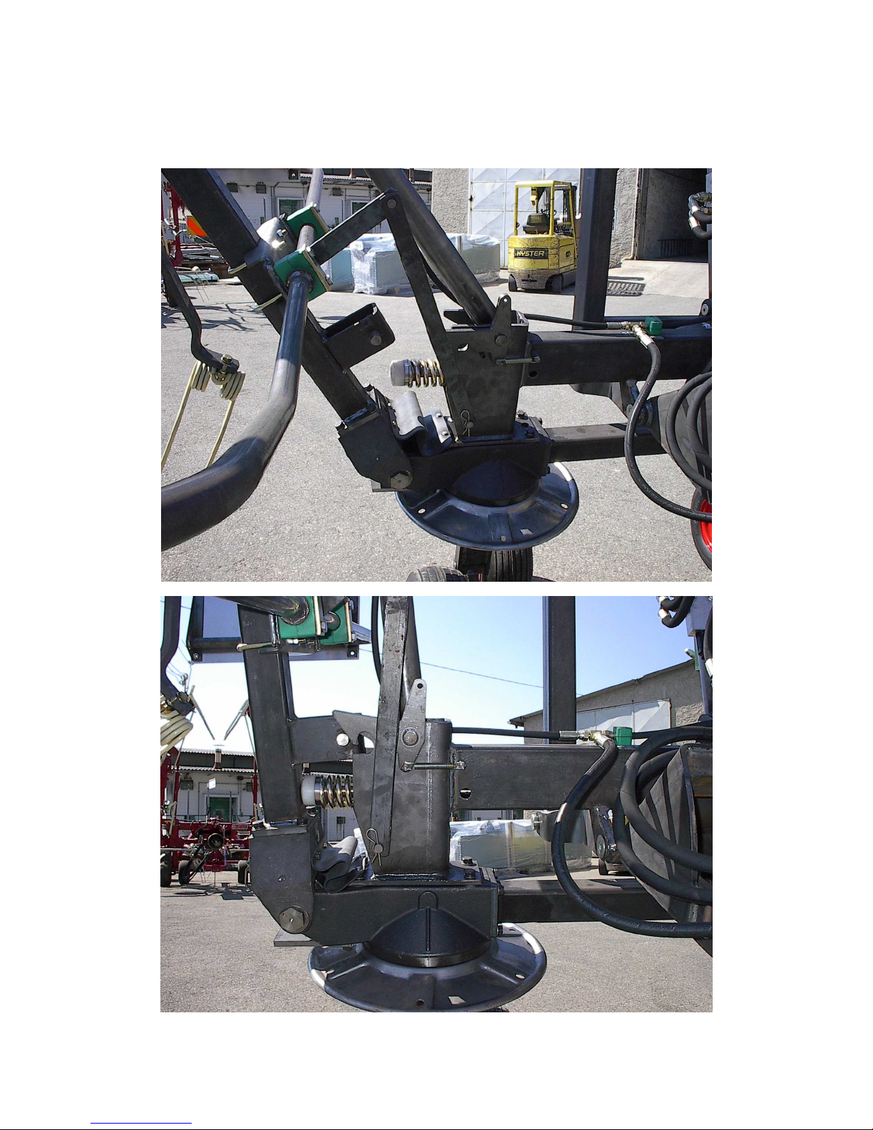
In order to assemble the spring rods, proceed as follows:
open the machine in its working position and connect the oleodynamic system to the tractor.
Insert the spring rod into position and then raise the side arms. As the arm rises, it compresses the spring.
Use the hole in the tube to uncover the hole on the spring guide rod. Stop the cylinder and insert the elastic
pin through the hole in the rod so that the pin does not touch the tube. The following photos show the entire
sequence.
Page 14
13
Use the flat drawrod to assemble the road sign plate supports. Once assembled, the sign plates should be
parallel to the ground. If not, adjust the support already assembled on the machine by unscrewing it and
moving it slightly in order to get the correct position.
Page 15
14
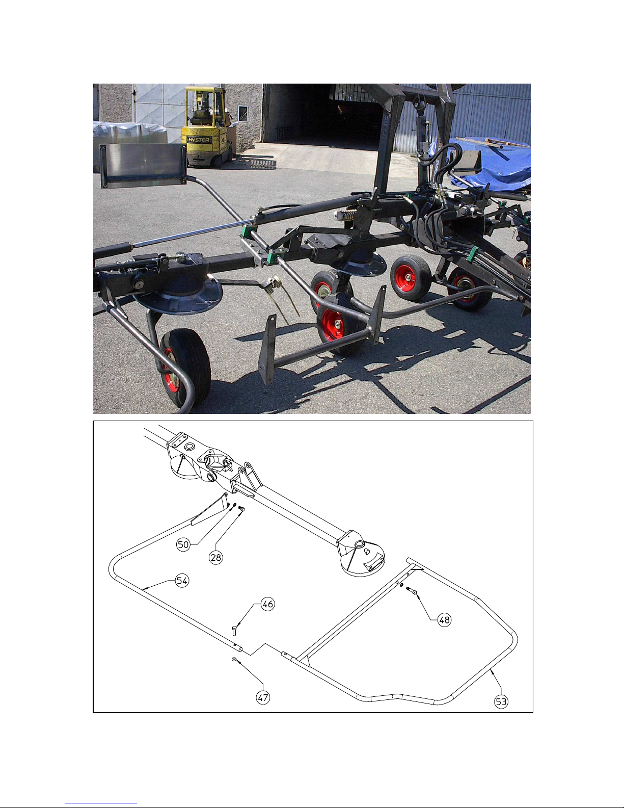
Assemble the guards whit screws 28 and 48
Attach the lateral guard 54 and 53 (LH)
to machine body using screws 28-46-48, nut 47 and washers 50.
In this step, you will use:
Item 46 : 1 screws M10x45
Item 47 : 1 nuts M10
Item 48 : 2 screws M12x50
Item 50 : 4 washers ø13 (ø0.51”)
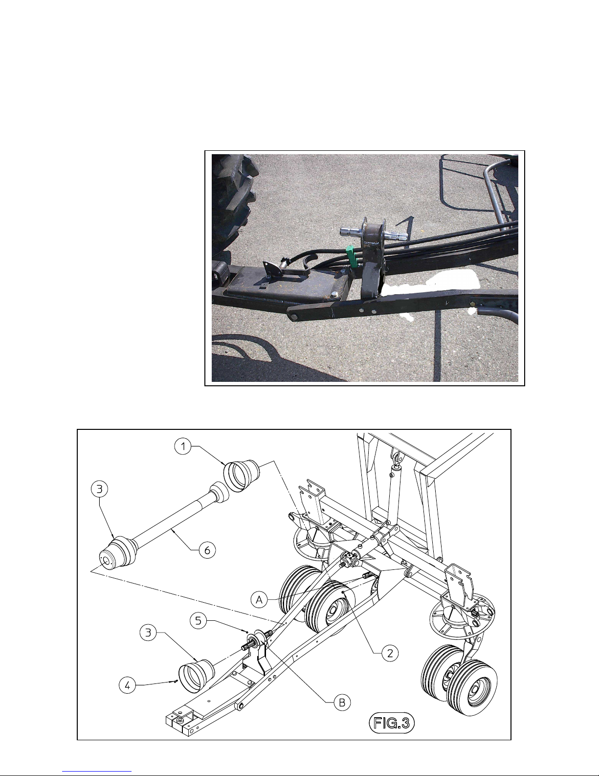
Assemble the cardan support.
Attach casing 1 to the central housing A and fasten using nuts 2.
Attach casing 3 to the support B and fasten using screw 4 and nuts 5.
Mounting cardan shaft 6
Page 16
15
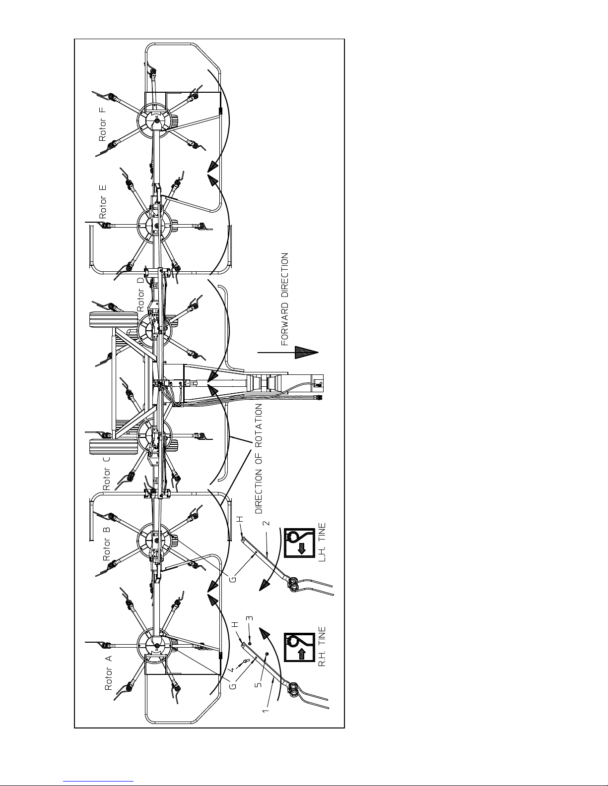
DIAGRAM OF TINE ASSEMBLY
Tine bars 1 (R) are attached to rotors
A – C – E. Tine bars 2 (L) are attached
to rotors B - D – F.
Attach tine bars 1 – 2 (R-L) to the
respective rotors, placing holes H of
tine bars 1 –2 over the screws already
in place on the lower central part of
rotors A – B – C – D – E – F and
fasten with nuts 3.
Insert screws 4 in the holes G
indicated on rotors A – B – C – D – E
– F and in tine bars 1 – 2 (R – L) and
fasten with nuts 5.
Assembly is now completed.
Page 17
16
ADJUSTMENT, PREPARATION AND USE
Connection to the tractor is highly dangerous. Take great care and carry out the entire operation in
strict compliance with the following instructions.
Nobody should go near the area between the tractor and the machine.
Check that the tractor is in good running order. Check the engine oil, gearbox oil, brake fluid and
cooling water levels as well as the tyre pressures.
Refer to the tractor operator’s manual.
ATTACHMENT MACHINE TO THE TRACTOR
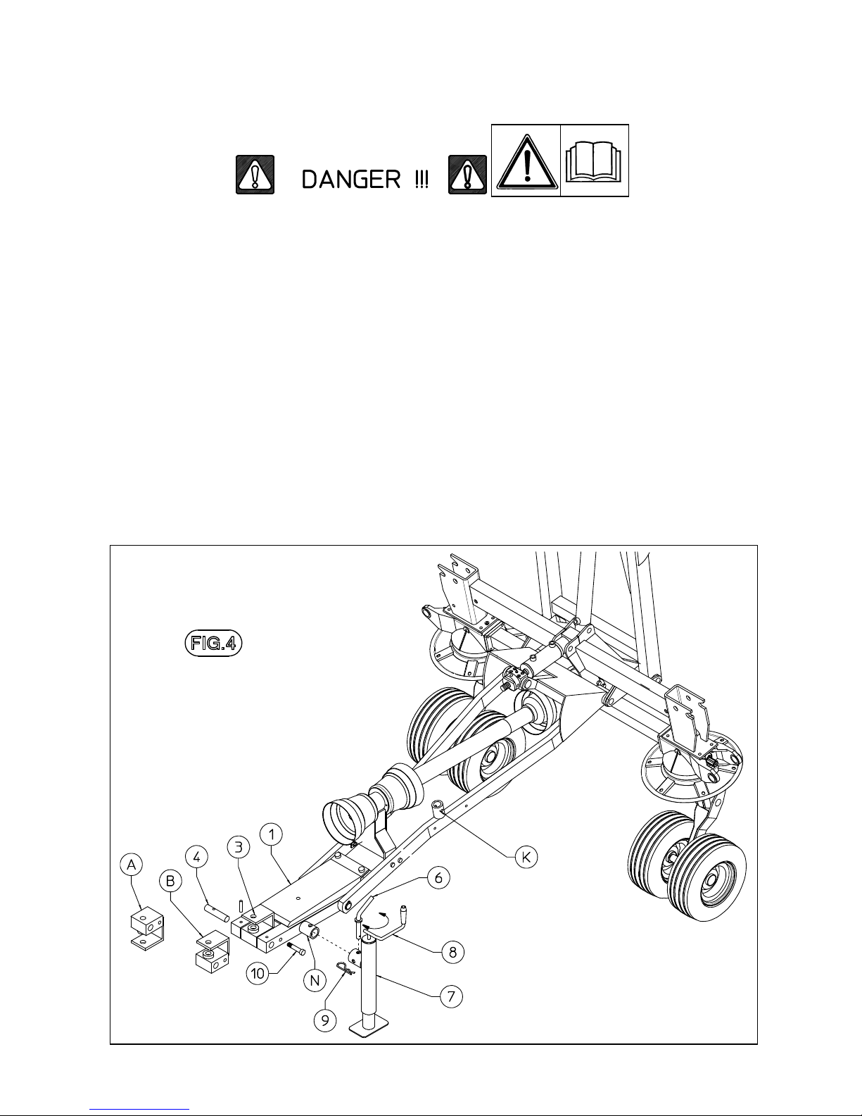
The attachment of pull-type machines to the tractor is very simple, as it is only necessary to couple
the drawbar hitch (3) to the tractor hitch using a pin of appropriate size, strength and shape. Always
use extreme care when reversing the tractor towards the machine.
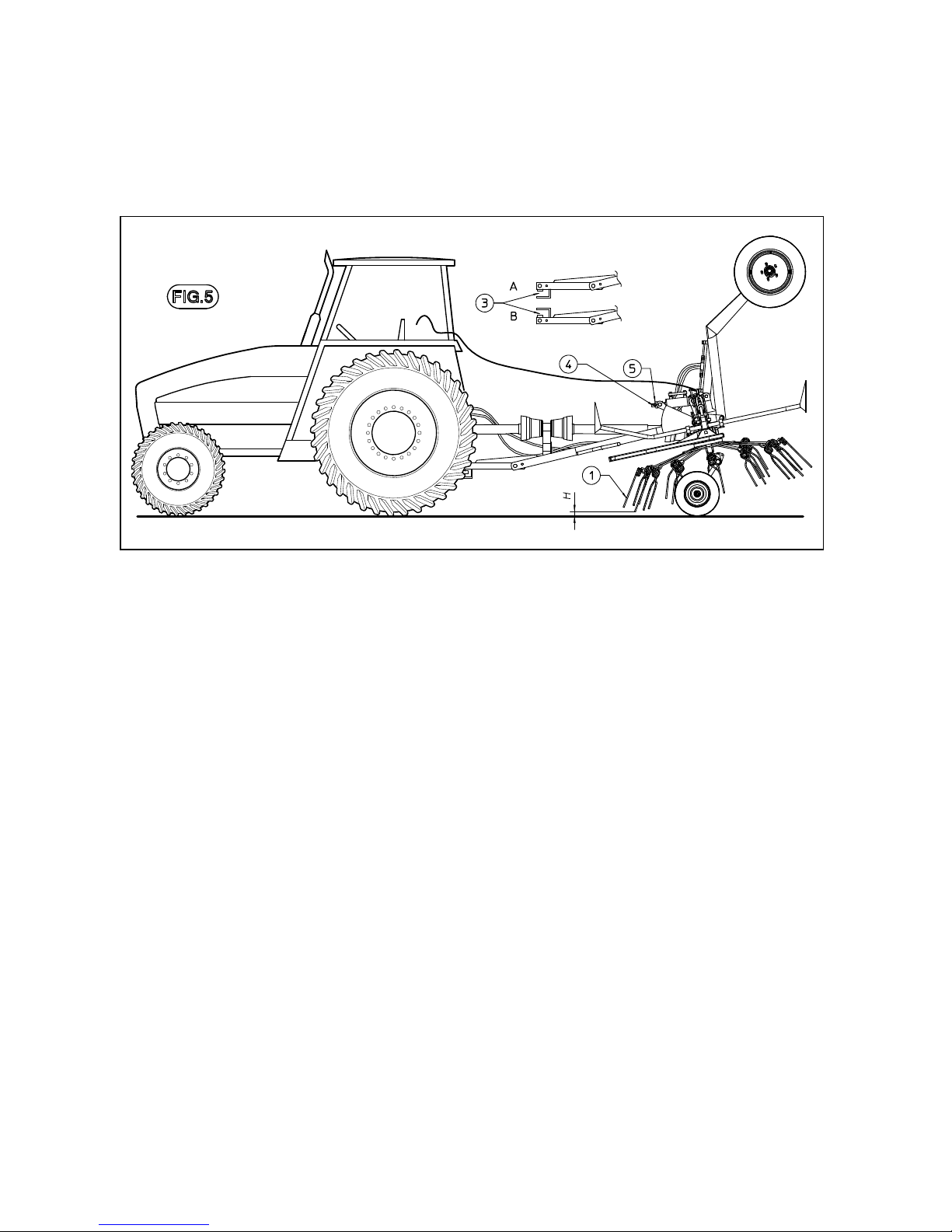
The drawbar hitch (3) can be set in different positions, using pin (4) turning the hitch upside-down
from (A) to (B), to allow coupling to all tractor types.
If the two-point crosspiece is used, lock the drawbar hitch (3) using the optional screws (10).
Attention: do not use screws (10) if the machine is hitched to the drawbar.
During transport and working the parking stand (7) must be shifted from position “N” to position
“K”. This is done by removing clip (9) and pin (6) an moving stand (7) out of the parking position.
Fasten parking stand (7) into the transport position using pin ((6) and clip (9).
Once this procedure is completed, insert the quick-release coupling the tractor socket.
Page 18
17
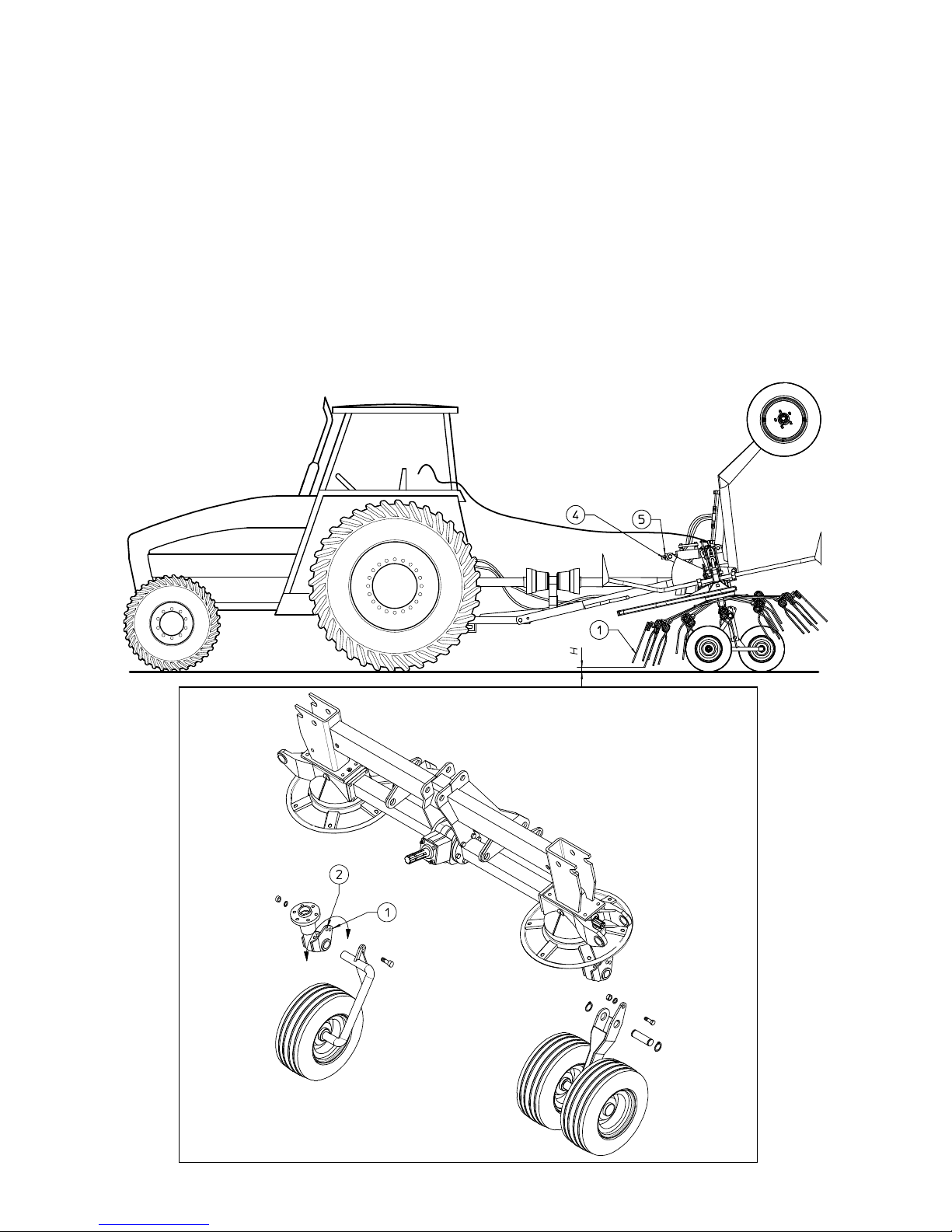
At this point, work carefully with the hydraulic distributor to make sure that the frame is completely
lowered, and then adjust the height of the tines (H) above the ground. To change the distance
between the tines and the ground, turn looking (4) and rotating the self looking nut (5), the tilt of the
machine relative to the ground is adjusted.
It is advised to adjust the front tine so that it is 1 3/8” from the ground.
If adjustment is too high, the forage will not be completely picked up and if it is too low, the forage
risks becoming dirty, the grass will be damaged and the double elastic tines will be worn down.
Before starting off for work, be sure that the machine is correctly assembled and in good operating
condition.
Page 19
18
Page 20
19
Preparation for transport
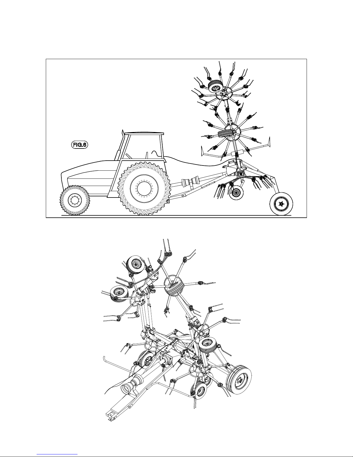
To arrange machine for transport position, first it is necessary to operate movement of axle and
drawbar. Valves mounted on cylinders make it possible, first partial movement of axle and then
of drawbar. After this operation lift side rotors checking that safety hooks lock the relevant pins.
Page 21
20
DISASSEMBLY OF THE TRACTOR
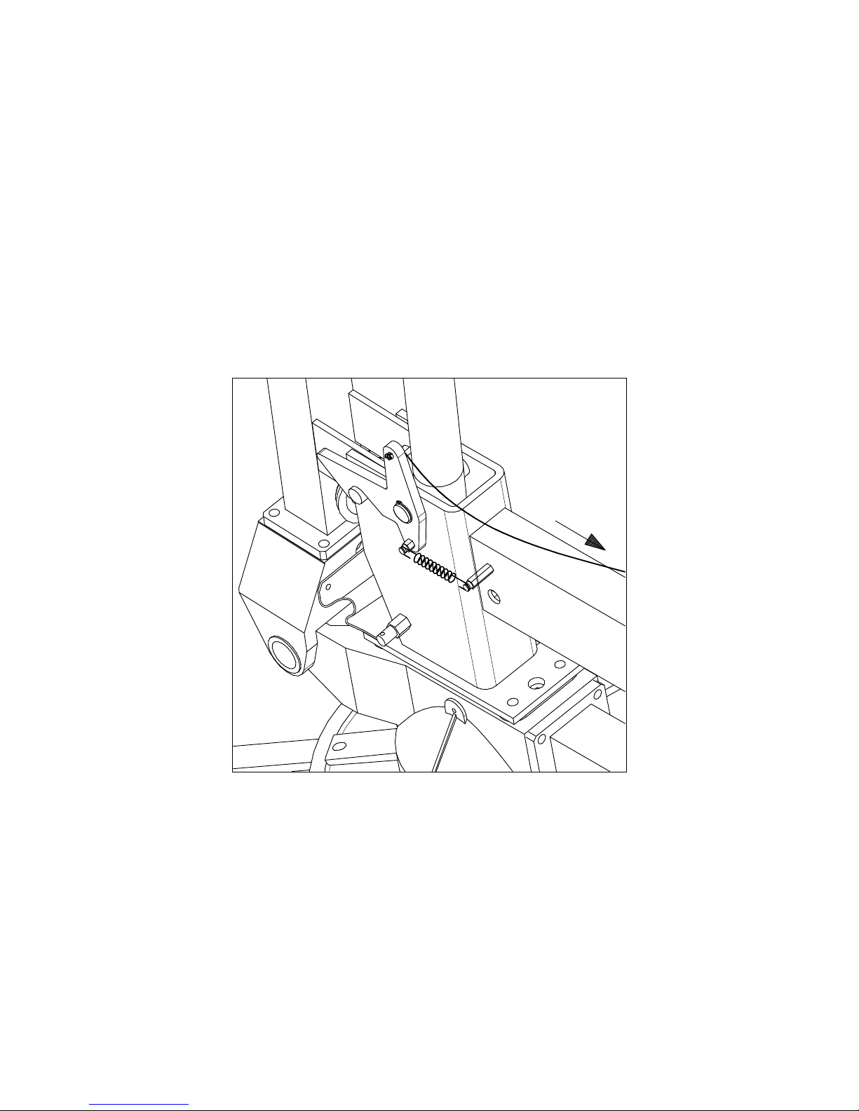
In order to park the rake, make sure that the ground beneath it is flat and is able to
bear the weight of the machine.
When the rake is raised and lowered, no one should be standing between the tractor
and the machine or near the machine.
Before disconnecting the machine from the tractor, use the hydraulic system to lower
the machine completely, then apply the brake and shut off the tractor. Dismount from
the tractor and place the parking stand in the vertical position (Fig. 4). Turn the crank
to raise the machine from the drawbar so that the hitch pin may be removed from the
tractor. Disconnect the quick-releases coupling . Disconnect the cardan shaft and lay
it against the crank. The tractor may now be moved away.
Attention: the machine should be in the high position only when being
transported.
Page 22
21
Page 23
22
Page 24
23
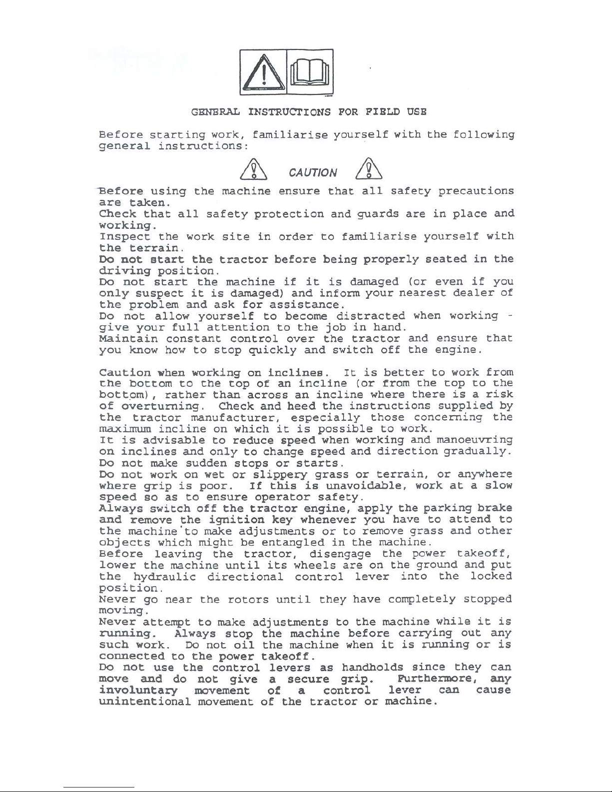
USE IN THE FIELD
In order to arrange machine for work it is necessary to operate rotors’ cylinders, so to release safety
hooks and then lower rotors completely and at this point operate hydraulic system, so to lift axle
and lower drawbar in order to have machine in working position. If work is not optimal adjust
distance of tine from ground.
If quantity of forage is high, inclination of machine may be increased acting on wheel brackets
moving them in second position.
Adjustment of gear speed and revs to work the machine
The gear speed and machine revs depend on:
• the amount of forage
• the type of ground
• the degree of dryness
The forage rake was designed for a maximum number of revs for the power take-off of 540 g/min.
We advise working with a rev number of 350-450 g/min. Gear speed should be limited so that the
rake works cleanly and the swath is well formed.
Page 25
24
Page 26
25
Page 27
26
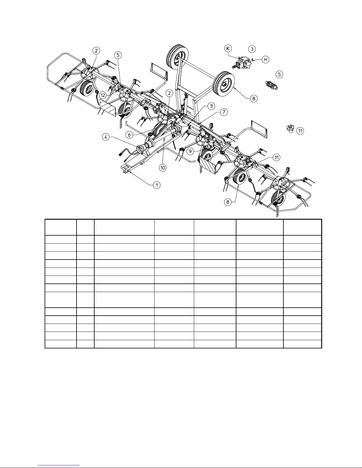
MAINTENANCE POINTS
Number Q.ty Description Operation Every hours Product to be
used
Notes
1 1 Bracket Greasing 20 Grease
2 6 Gearbox Greasing 40 Grease
3 1 Central housing Greasing 80 Grease A
4 1 Shaft Greasing Grease B
5 4 Universal joint Greasing 8 Grease
6 1
Adjustment support
Greasing 20 Grease
7 4 Pin Greasing 50 Grease
8 10 Tyres Check
pressure
Compressor C
45 psi
9 2 Axle tandem Greasing 20 Grease
10 1 Cardan shaft Greasing 8 Grease
11 6 Rotor hubs Greasing 24 Grease
12 8 Swivel hinge pin Greasing 40 Grease
1 Cardan shaft Greasing 8 Grease
General checking of bolts, security pins and split pins to be carried out initially after the first 8 hours
of use. Subsequently every 50 hours and whenever the machine is laid up for extended periods.
A = The complete lubrication of housing 1 is done the first time at the manufacturer’s plant, after
which it must be topped up periodically, as according to the lubrication points table. A complete
change or fill is necessary only for the replacement and /or repairing of the entire housing or
internal parts. In this case, it is necessary to: remove caps and inject the grease, using grease
pump, into hole H until the grease comes out of hole K. Then screw caps back into place on
housing.
B = Each time the Cardan shaft is disconnected and Whenever the machine is stopped, we
recommended that you clean the power takeoff shaft and replace the protective cover.
C = Each time the machine is connected to the tractor.
# Additives of a type permitted by anti-pollution regulations.
Page 28
27
Page 29

28
NOISE AND VIBRATION
Noise affecting the tractor driver (from the machine only) is less than 80dB.
Vibration from the machine affecting the upper body and limbs of the driver is insignificant and is
lower than the values given in Point 3.6.3 of Enclosure 1 of the Machine Directives (89/392/EEC,
91/386/EEC)
THE FOLLOWING SHOULD BE NOTED IF THE MACHINE IS SCRAPPED
The machine consists mainly of ferrous material, which must be disposed of according to the
regulations in force in the country concerned.
There is also a small amount of plastic, which must be disposed of according to the regulations in
force in the country concerned.
There is very small amount of residual grease, which must be disposed of according to the
regulations in force in the country concerned.
Page 30

1
Zona Industriale-Viale Grecia, 8
06018 TRESTINA-(Perugia)-ITALY
Tel. +39.075.8540021-Telefax +39.075.8540523
e-mail: [email protected] www.sitrex.com
Spa
 Loading...