


ASSEMBLY, USE AND MAINTENANCE
SPARE PARTS LIST
FINISHING MOWERS
SM/230
01/07

2
WARRANTY
On delivery, check that the machine has not been damaged during transport and that
all the attachments are present. Claims must be made in writing to the agent within 8
days of receipt.
The manufacturer warrants new machinery at the time of delivery to the original
purchaser to be free from defects in material and workmanship if properly set up and
operated in accordance with this Operator’s Manual.
The manufacturer undertakes to repair or replace free of charge any defective part
which should be returned by the purchaser (freight prepaid) and found to be defective
by inspection authorized by the manufacturer during the warranty period.
This warranty will be valid for 12 (twelve) months from the delivery of goods to the
original purchaser .
In case the customer is not in a position to return the defective part to the
manufacturer , the manufacturer cannot be held responsible for any cost due for
repair or replacement of any part of the machine , he will only supply the part(s)
required for the repair and/or replacement.
The warranty is null and void when it is evident that the machine has been improperly
used or however repaired without authorization.
The manufacturer undertakes no responsibility for any obligation or agreement
reached by any employers, agents or dealers, which are not in compliance whit the
above warranty . The manufacturer cannot be held responsible for the consequent
damages. This warranty substitutes any other warranty , express or implied , and any
other manufacturer’s obligation.
CHAPTHER
1) GUIDE TO THE SIGNS
2) General summary of safety and accident-prevention instructions
3) PRODUCT IDENTIFICATION
4) DELIVERY AND ASSEMBLY
5) ADJUSTMENT, PREPARATION AND USE
6) MAINTENANCE DIRECTIONS
7) SPARE PARTS LIST
3
1) GUIDE TO THE SIGNS AND SYMBOLS USED ON THE
MACHINE
IMPORTANT
These signs and symbols give information to the operator on how to make the best
use of the machine so as to prolong life, avoid damage, optimise work and, above all,
to avoid injury to the operator and anyone within range of the machine.
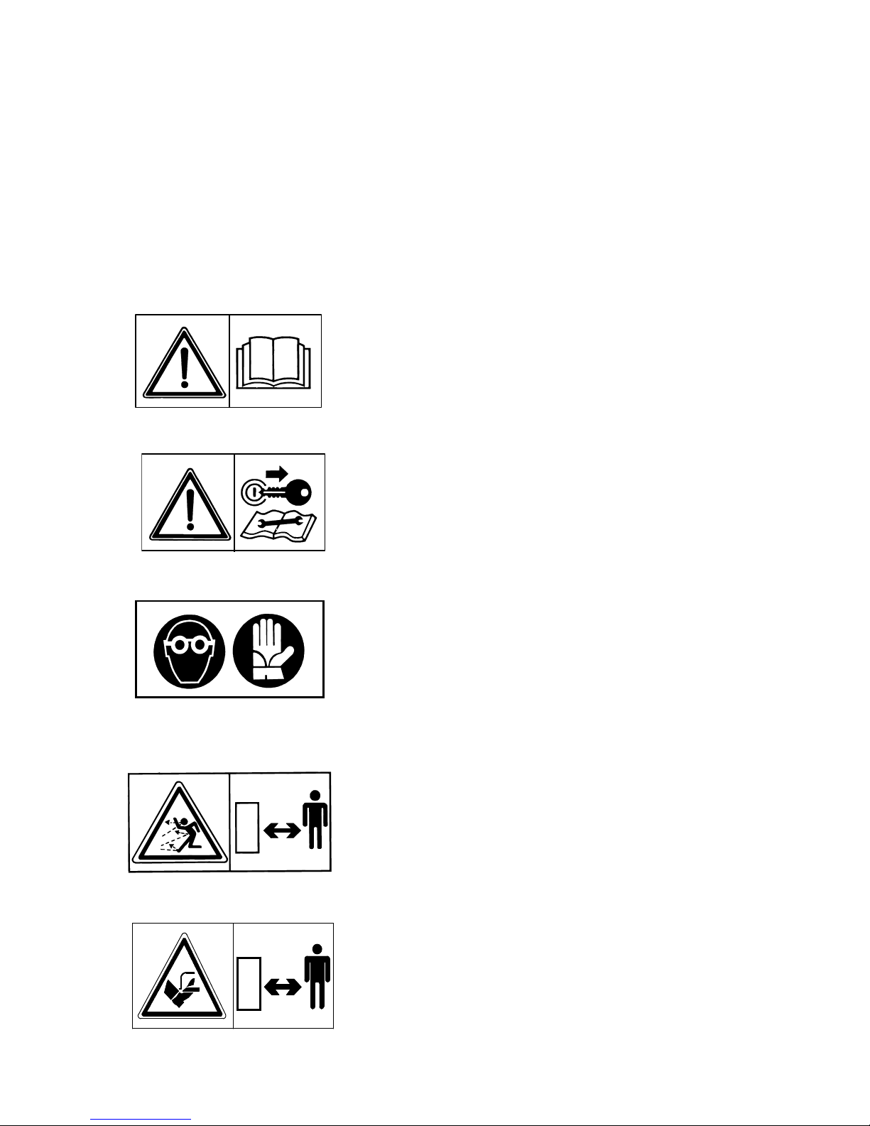
WARNING SIGNS
1) Before beginning operations, read the instruction
manual carefully.
2) Before doing any maintenance or repair work,
stop the machine at a suitable spot. Turn off the
tractor motor, apply the brake, remove the key from
the ignition and consult this manual.
3) This is a warning to use proper accident
protection when carrying out maintenance and
repairs
DANGER SIGNS
4) Risk of possible ejection of blunt objects.
Keep a safe distance from the machine.
5) Indicates that there is a risk of cutting one’s foot.
Keep your distance.

4
6) Indicates that there is a risk of cutting one’s hand.
Keep your distance.
7) Warns the danger of cutting blade.
8) Generic danger.
9) Indicates that it is dangerous to touch the cardan
(P.T.O.) shaft. For all the other information regarding the
cardan shaft, see the use and maintenance booklet
specifically for the cardan shaft which, together with this
manual, makes up the documentation on safety, use and
maintenance of the machine.
10) Indicates an impeding dangerous situation which, if
not avoided, will cause death or severe personal injury.
11) This indicates a potential danger which, if not
avoided, could cause serious personal injury. It also
indicates danger when removing protective guards.
12) Indicates a potentially dangerous situation which,
if not avoided, can provoke less severe or minor
injuries.

5
INDICATION SIGNS
13) This indicates to check the oil level.
14) This indicates to check the belts tension.
15) This indicates the cap oil level.
16) Indicates a greasing points.
17) Shows the direction of rotation of the power takeoff
and the maximum number of revolutions.
NOTE: All the signs and symbols so far shown appear in the manual. Some of these
are also on the machine: for their location, the diagram on page 10.

6
GENERAL SUMMARY OF SAFETY AND ACCIDENT
PREVENTION INSTRUCTIONS
Read all the directions carefully before using the machine. When in doubt, seek
advice from the manufacturers.
The manufacturing company declines all responsibility for non-compliance with the
following safety and accident-prevention instructions.
1- Pay attention to the danger signs and symbols in this manual and on the machine.
2- Do not touch moving parts.
3- All work on the machine (including adjustments) must always be carried out with
the tractor immobilized and the engine switched off.
4- On no account may persons or animals be carried on the machine.
5- Driving the tractor with the machine connected is absolutely forbidden to persons
lacking suitable experience, or who are in poor health, or who do not have a
suitable driving license.
6- All accident-prevention measures recommended in this manual should be
scrupulously observed.
7- Connecting the machine to the tractor creates a different weight distribution on the
axles and so it is essential to ensure that the tractor-machine combination is stable
in all anticipated working conditions. It is therefore necessary to have exact
instructions from the tractor manufacturers. If such instructions are not available,
suitable tests should be conducted in safe conditions in order to assess stability.
8- Once the machine is connected, it can only be controlled through a Cardan shaft
complete with the required overload protection and guard secured with the
appropriate small chains. Be aware of the rotational direction of the Cardan shaft.
9- Before operating the tractor and machine, check that all transport and operational
safety devices are complete and working.
10- When driving on public roads, you should comply with the Highway Code
regulations for the country concerned.
11- Do not exceed the tractor axle maximum weight and the total mobile weight. Heed
transport regulations.
12- Before starting work, familiarize yourself with the control devices and how they
work.
13- Wear suitable clothes. Do not wear clothing which is loose or which could
become entangled in rotating or moving parts.
14- Connect the machine to a suitably powerful tractor by using an appropriate lifting
unit and in accordance with instructions.
7
15- Take maximum care when connecting and disconnecting the machine to and from
the tractor.
16- The machine and any road transport attachments must bear the appropriate signs
and symbols and have suitable protection.
17- Never leave the driving seat when the tractor is running.
18- It is extremely important to appreciate that road holding, steering and braking may
be significantly affected with the machine attached.
19- When turning corners with the machine attached, be aware of the fact that the
centrifugal force will alter due to the change in the center of gravity.
20- Before engaging the power takeoff check the preset revolution speed. Do not
change speed from 540 rpm to 1000 rpm.
21- Under no circumstances should anybody stand near the machine or any moving
parts. It is the duty of the operator to ensure that this requirement is respected.
22- Before leaving the tractor, lower the machine with the lifting unit, stop the engine,
apply the parking brake and remove the ignition key from the instrument panel.
23- Under no circumstances should anybody go between the tractor and the machine
when the engine is running and the Cardan shaft is engaged, especially without
first having applied the parking brake and placed chocks against the wheels.
24- Before connecting or disconnecting the machine to or from the 3-point linkage,
put the lifting unit lever into the locked position.
25- The connection pins on the machine must match the connection sockets on the
lifting unit.
26- During transport, secure the lateral lifting arms with the appropriate chains and
tighteners.
27- When the machine is raised during road transport, put the tractor's hydraulic lifter
lever into the locked position.
8
28- Only use the Cardan shaft provided by the manufacturer and, in case of
replacement, substitute it with one having the same characteristics.
29- Regularly check all protection on the Cardan shaft. This should always be in
excellent condition and securely fixed.
30- It is important to ensure that the protection on the Cardan shaft is complete.
31- Connection and disconnection of the Cardan shaft must be carried out with the
engine switched off.
32- Pay particular attention to the correct connection and safety of the Cardan shaft
and the power takeoffs on the machine and the tractor.
33- Prevent the cardan shaft protection from rotating using the chains supplied.
34- Before engaging the power takeoff, make sure that there are no people or animals
in the vicinity and that the selected engine speed corresponds to that permitted.
Never go above the maximum permitted.
35- Do not engage the power takeoff when the engine is not running.
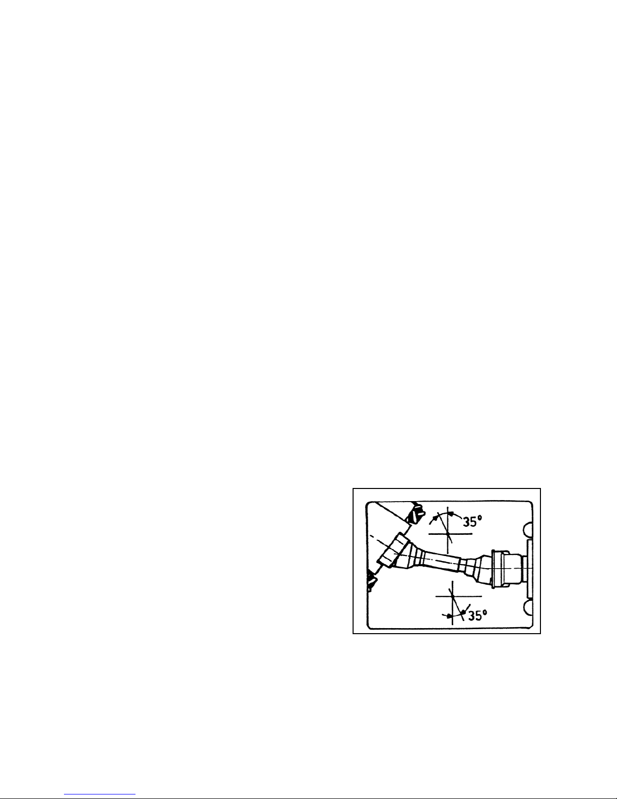
36- Always disengage the power takeoff when the Cardan shaft is at too wide an angle
(it should never be more than 35° Fig. 3.2) and when it is not in use.
37- Only clean and grease the Cardan shaft when the power takeoff is disengaged, the
engine is off, the parking brake is applied and the ignition key is removed.
38- On disconnecting the Cardan shaft, replace the protective hood on the power
takeoff shaft.
39- Prolonged use of the machine can cause the drive boxes to become hot. To avoid
any risk of getting burnt, avoid touching these areas both during se and some time
afterwards.
40- Periodically check screws and nuts for
tightness and grip. Tighten if necessary.
41- When carrying out maintenance work or
replacing the blades, raise the machine and
rest on adequate supports.
42- Use the quantities of grease and oil
advised.
43- Spare parts must meet the requirements as
defined by the manufacturer. Use only
original spare parts.
44- Safety decals must always be clearly
visible. They must be kept clean and
replaced if they become too illegible (they can be ordered from the agent if
necessary).
45- The instruction booklet must be available for the lifetime of the machine.
9
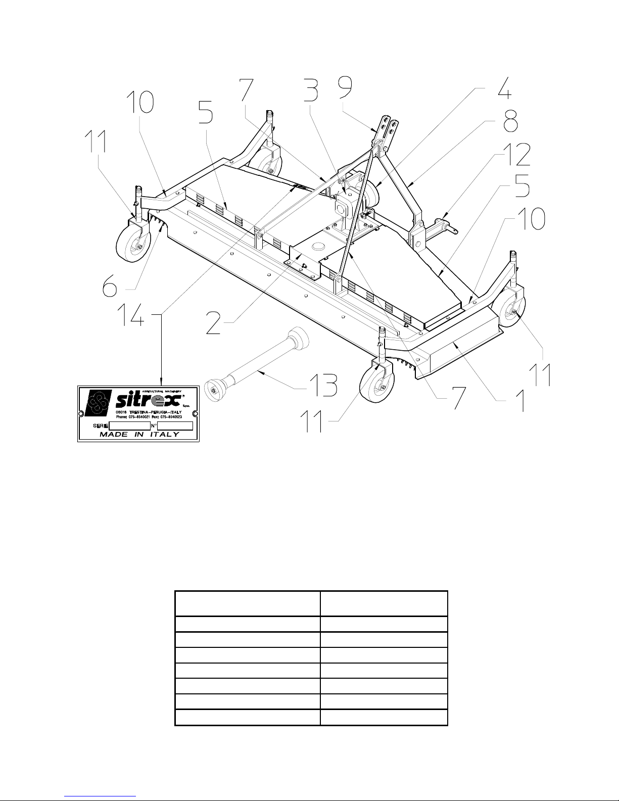
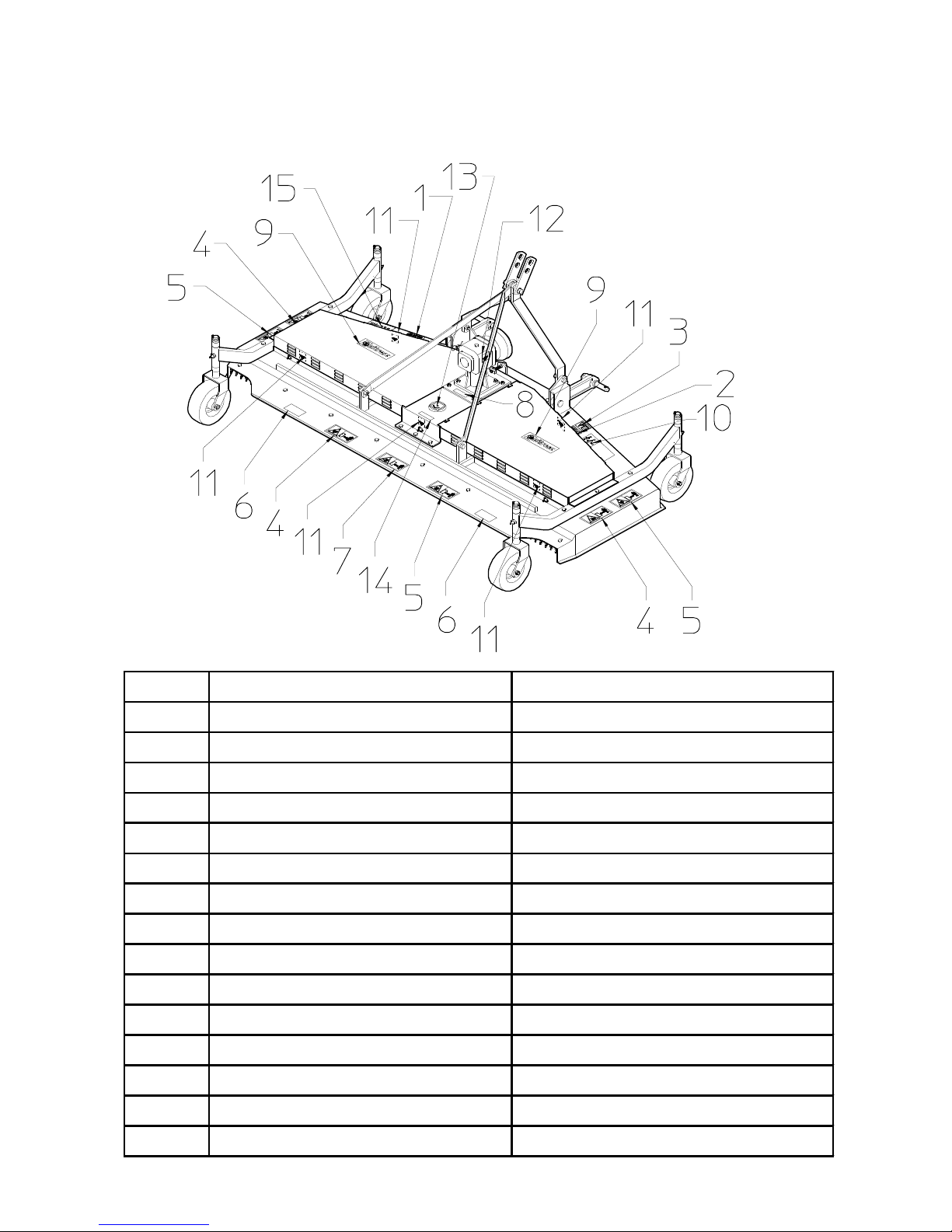
3) PRODUCT IDENTIFICATION
MAIN PARTS
1) MACHINE CASING 8) 3rd POINT HITCH
2) GEARBOX SUPPORT 9) HITCH
3) GEARBOX 10) AXLES
4) PROTECTIVE CAP 11) WHEEL UNIT
5) PROTECTIVE GUARDS 12) PIN LEVER
6) PROTECTIVE CHAIN 13) CARDAN SHAFT
7) TIE ROD 14) IDENTIFICATION PLATE
TECHNICAL DATA
All data are indicative. Sitrex reserves the right to change them without advance notice.
SPECIFICATIONS SM/230
Cutting width 90" - 2300 mm
Cutting heigth 1" to 4" - 25 to 100 mm
Number of blades 5
Blade RPM 2630
Standard PTO RPM 540
PTO Tractor requirement 30 to 60 HP
Weight 685 LBS - 310 KG
10
LOCATION OF SIGNS AND SYMBOLS ON THE MACHINE
EMPLACEMENT DES ETIQUETTES SUR LA MACHINE
ITEM DESCRIPTION DESCRIPTION
1 Serial number plate Plaquette d'identification
2 See drawing 2 page 3 Voir dessin 2 page 3
3 See drawing 1 page 3 Voir dessin 1 page 3
4 See drawing 5 page 3 Voir dessin 5 page 3
5 See drawing 6 page 4 Voir dessin 6 page 4
6 See drawing 8 page 4 Voir dessin 8 page 4
7 See drawing 4 page 3 Voir dessin 4 page 3
8 See drawing 13 page 5 Voir dessin 13 page 5
9 Sitrex decal Etiquette commerciale
10 See drawing 7 page 4 Voir dessin 7 page 4
11 See drawing 16 page 5 Voir dessin 16 page 5
12 See drawing 15 page 5 Voir dessin 15 page 5
13 See drawing 17 page 5 Voir dessin 17 page 5
14 See drawing 14 page 5 Voir dessin 14 page 5
15 Decal with model of machine Etiquette du modele de machine
11
4) DELIVERY AND ASSEMBLY
CHECKING THE MACHINE ON DELIVERY
All parts are carefully checked before dispatch or delivery.
On receiving the machine, ensure that it not been damaged during transport. If
damage has occurred, contact the dealer concerned. How the machine is lifted will
depend on the model and the type of packing. Details are given below. The packing
can vary from country to country depending on transport requirements.
Lift the machine using a forklift truck, crane or other suitable equipment of sufficient
capacity after first checking the weight of the configurations in the table given below.
Check the stability and positioning of the load on the forklift truck forks or crane
hook. Keep the load as low as possible during movement for maximum stability and
to ensure that the operator has maximum visibility. If a forklift truck is used, ensure
that the forks are positioned as wide apart as possible.
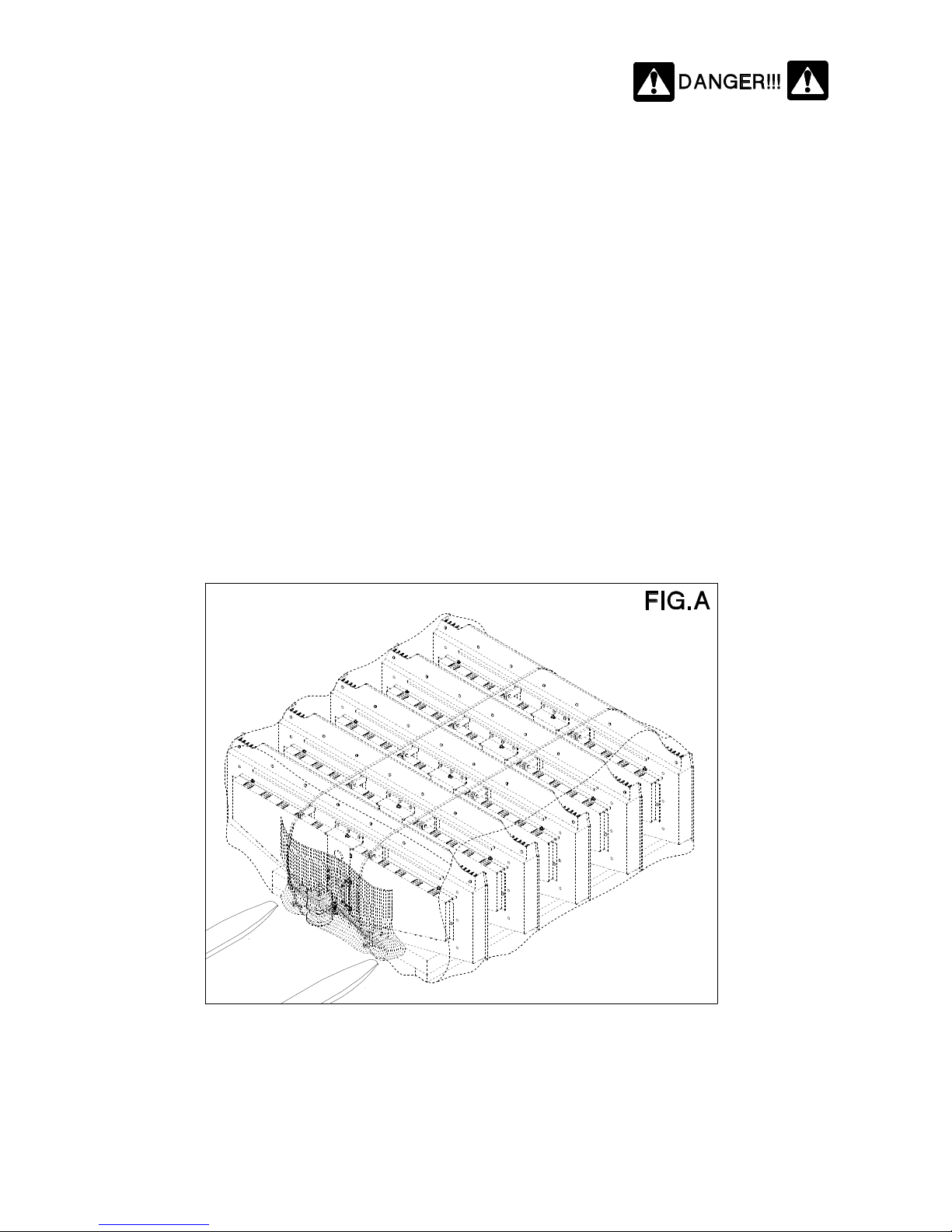
Fig. A: represents the standard packaging for the lawn mower with rear grass ejector.
(Usually , there are 5 crated machines, except for orders of lower quantity )

12
Notes :
1) Slightly different packaging from those represented may occasionally be used,
depending on the methods of transport or handling.
2) The packing consist mainly of wood which should be disposed of according to
the laws in force in the country where the machine is used. The plastic film
should also be disposed of according to the laws in force in the country where
the machine is used.
3) In the case of further transportation, make sure the machine is well secure on
the transports means.
MOWERS WEIGHT (n°1 machine) KG – LBS : 310 – 685
In case of handling keep in mind the total weight of machines ( 5 machines
weight approximately kgs. 1.600 – Lbs.3.525 , standard crating ) otherwise,
calculate the weight based on the quantity of machines.
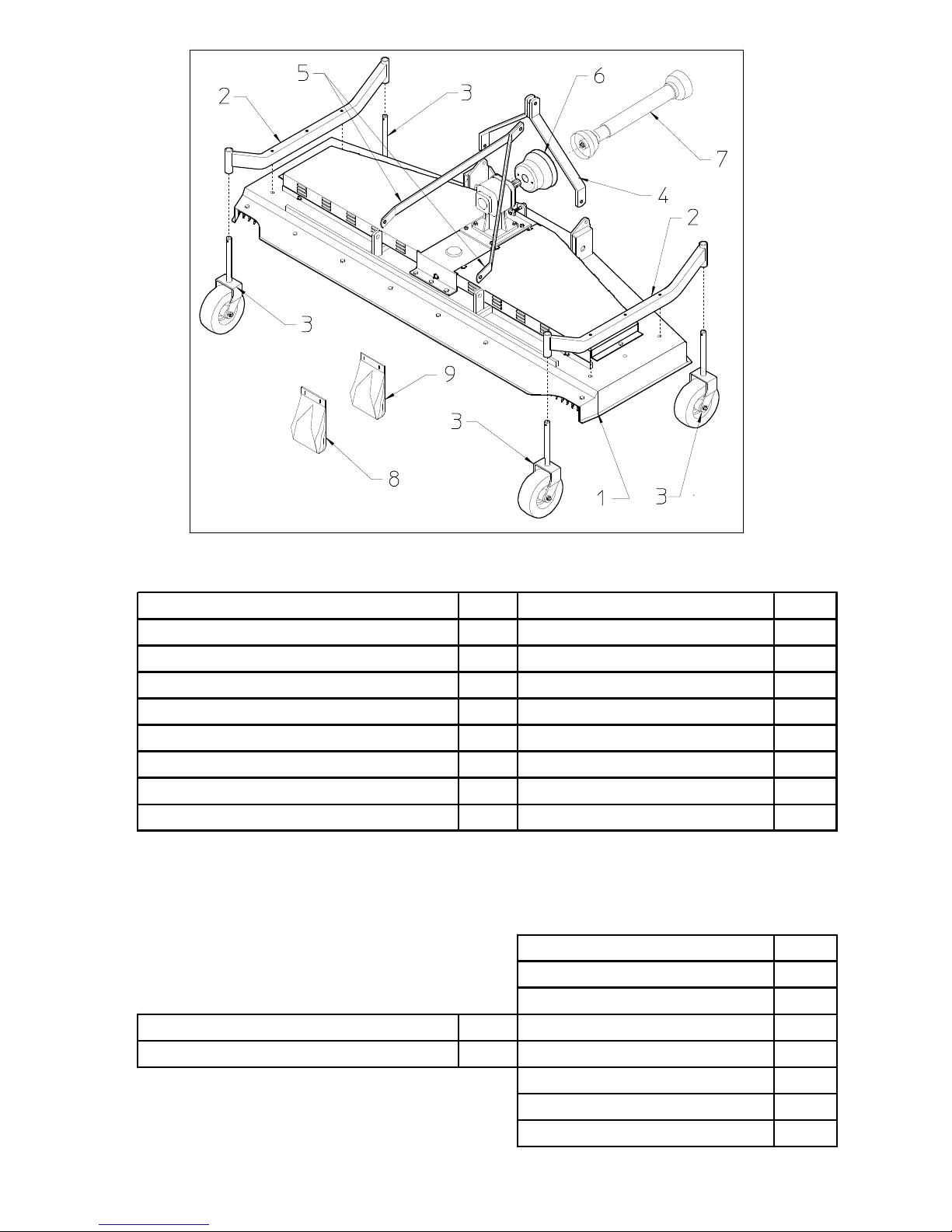
The unpacked machine is composed of the following parts (see pg.13) :
(SEE NEXT PAGE)
Machine with rear grass ejector
1) Machine casing Q.ty 1
2) Wheel axles Q.ty 2
3) Wheel unit Q.ty 4
4) 3rd Point hitch Q.ty 1
5) Tie rods Q.ty 2
6) Guard Q.ty 1
7) Cardan shaft Q.ty 1
8) Bag of nuts and bolts Q.ty 1
9) Bag accessories Q.ty 1
13
The contents of item 8 (bag) are as follows :
The contents of item 9 (bag) are as follows:
Standard mowers Front mowers
Shim ø30-40x2 - 1,18"-1,57"x0,08" Q.ty 4 Flat washer ø8,5 Q.ty 2
Shim ø30-40x6 - 1,18"-1,57"x0,24" Q.ty 4 Flat washer ø12,5 Q.ty 4
Shim ø30-40x12 - 1,18"-1,57"x0,47" Q.ty 4 Spring washer ø13 Q.ty 4
Shim ø30-40x25 - 1,18"-1,57"x0,98" Q.ty 4 Grease nipple M6 Q.ty 4
Shim ø30-40x32 - 1,18"-1,57"x1,26" Q.ty 4 Split pin ø8 (BS 8) Q.ty 4
Screw M12x35 Q.ty 4 Split pin ø3 (BC 3) Q.ty 2
Screw M12x90 Q.ty 5 Pin with grower and nut Q.ty 2
Screw M8x16 Q.ty 2 3rd Point bush Q.ty 2
Self locking nut M12 Q.ty 5 Pin ø19 Q.ty 2
3rd Hitch Q.ty 1
Lower hitch Q.ty 2
Counterplate Q.ty 2
3rd Hitch Q.ty 1 Screw M12x80 Q.ty 4
Lower hitch Q.ty 2 Nuts M12 DIN 980 Q.ty 4
Flat washer ø13 Q.ty 4
Pin ø22x110 Q.ty 2
Split pin ø10 (BS 10) Q.ty 4

14
ASSEMBLY
Assembly is highly dangerous and must be carried out in strict accordance with the
following instructions. We recommend that assembly be performed by qualified
personnel. We also recommend that assembly be carried out in a flat, open area with
no people (particularly children) nearby who could be severely injured if they were to
touch or move any parts of the machine.
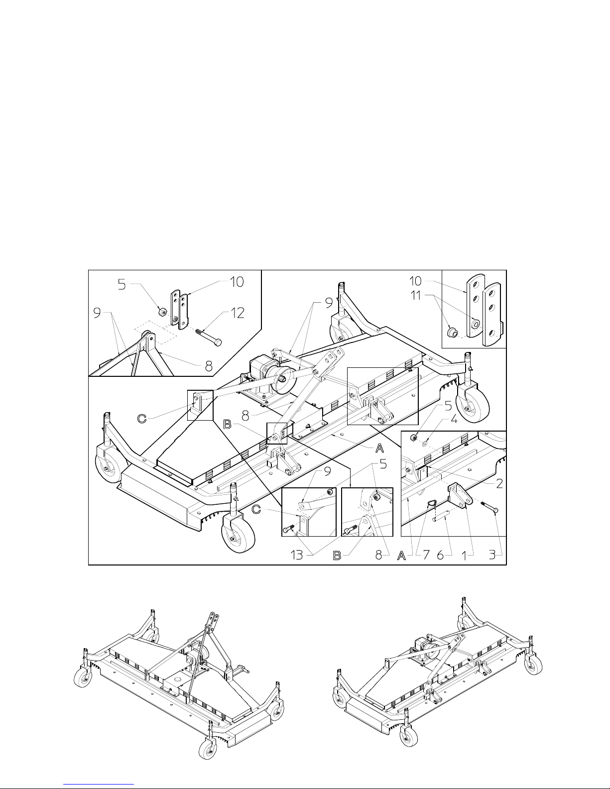
STEP “A”
Keep the main casing approx. 300-500
mm (12”-20”) above the ground, resting
it on suitable supports or on the forks
of a forklift.
Fit the guard 1 to the central gearbox 2
using the flat washers 3 and the screws 4.
In this step, you will use:
Item 3: 2 screws M8x16 (0.31” x 0.63”)
Item 4: 2 flat large washers ø8.5 (ø0.33”)
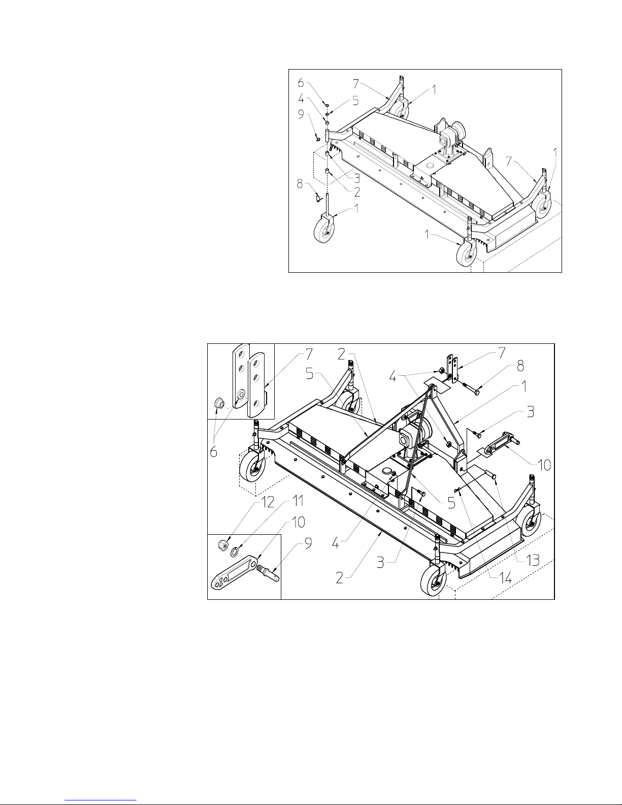
STEP “B”
Preliminarily remove screws 1 and
bushings 2 used for shipping.
Fit the axles 4 to the machine casing 3
using flat washers 6, spring washers5
and screws 1.
In this step, you will use:
Item 1: 6 screws M12x90 (0.47” x 3.54”)
Item 5: 6 spring washers ø13 (ø0.51”)
Item 5: 6 flat large washers ø13 (ø0.51”)
(Reuse the two M12x90 screws removed,
pos. 1; the two bushings are no longer
needed).
15
STEP “C”
The order of assembly for spacers 2-34-5-6 depends on the cutting height
you wish to obtain (see pg.21). A
standard assembly is described in this
step.
Add spacers 2-3 to the wheel assemblies
1 and then insert the entire assembly in
the axle seats 7. Add spacers 4-5-6 to
the wheel assemblies 1 now inserted in
the axle seats 7 and fasten the entire unit
with split pins 8.
Fit the grease nipples 9 to the axle
seats 7.
In this step, you will use:
Item 2: 4 shim ø30-40x32 (ø1.18”-1.57”x 1.26”)
Item 3: 4 shim ø30-40x25 (ø1.18”-1.57”x 1”) Item 6:4 shim ø30-40x2(ø1.18”-1.57”x0.08”)
Item 4: 4 shim ø30-40x12 (ø1.18”-1.57”x 0.47”) Item 8: 4 split pin ø8 (ø.31”)
Item 5: 4 shim ø30-40x6 (ø1.18”-1.57”x 0.24”) Item 9: 4 grease nipple M6 (0.24”)
STEP “D”
Fix the 3rd point hitch 1
to the correct seats on
the main casing 2 using
the screws 3 and nuts 4.
Do not fully tighten
nuts 4. Fix the tie rods
5 to the correct seats on
the main casing 2 using
the screws 3 and nuts 4.
Do not fully tighten
nuts 4. First fix the
bushes 6 onto the
hitch 7. The lug of the
bush 6 must be
positioned on the inside
of the hitch 7. The
hitch 7 with secured bushes 4 must be fixed to the 3
rd
point hitch 1 and tie rods 5 using
screw 8 and nut 4. Now fully tighten the nuts 4. Fit the levers 10 to the correct seats on the
main casing 2 and secure it with the pins 13 and split pins 14. Fix pin 9 on to the lever 10
and lock it with spring washer 11 and nuts 12. N.B.: There are two holes at one end of lever
10 in order to attach it to the machine. To choose which holes should be used, see page 22.
In this step, you will use:
Item 3: 4 screws M12x35 (0.47” x 1.38”)
Item 4:
5 nuts M12 (0.47”) Item 12: 2 nuts M22x1.5 (0.87” x 0.06”)
Item 8: 1 screw M12x90 (0.47” x 3.54”) Item 13: 2 pins ø19-25x50 (0.73”-1”x 2”)
Item 11: 2 spring washers ø23 (ø0.91”) Item 14: 2 split pins ø3 (ø0.12”)
16
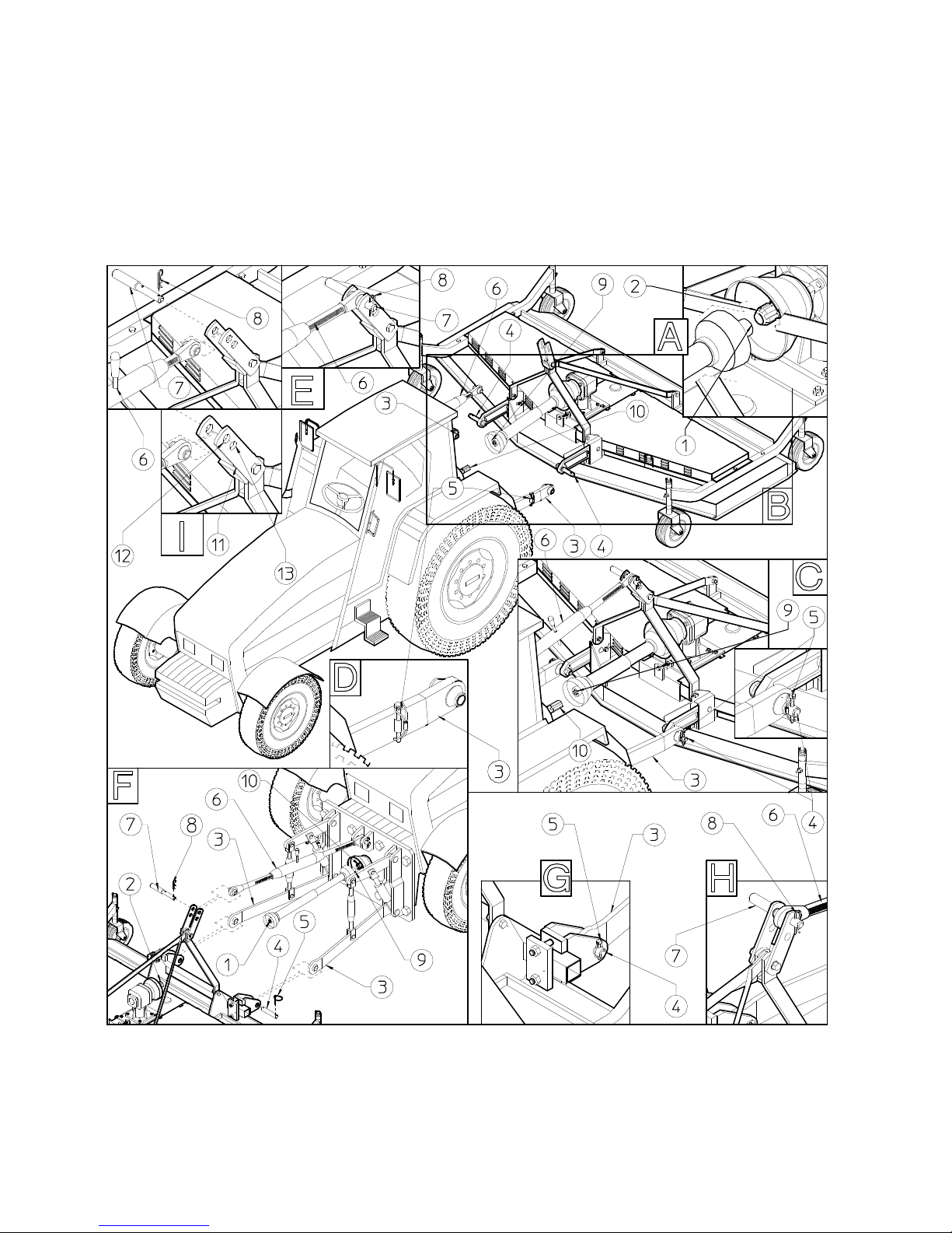
STEP “E”
SPECIAL MODELS
For the assembly of the front version of the mower, the preceding steps apply. Here we
describe briefly what is different. Fasten brackets 1 and counter plates 2 to part “A” of the
machine body using screws 3, washers 4 and nuts 5. Insert pin 6 into bracket 1 and fasten
with split pins 7. Fix the 3
rd
point hitch 8 to the correct seats “B” on the main casing using
the screws 14 and nuts 5. Do not fully tighten nuts 5. Fix the tie rods 9 to the correct seats
“C” on the main casing using the screws 14 and nuts 5. Do not fully tighten nuts. To
assemble together pieces 5(1 pc.)-8-9-10-11-12-13 shown in the details, follow the
instructions given in step “D”. When all pieces are assembled, finish tightening nuts 5.
In this step, you will use:
Item 3: 4 screws M12x70 (0.47” x 2.76”) Item 4: 4 washers ø13 (ø0.51”)
Item 5: 9 nuts M12 (0.47”) Item 6: 2 pins ø22x110 (0.87” x 4.33”)
Item 7: 4 split pins ø10 (ø0.39”) Item 7: 4 split pins ø10 (ø0.39”)
Assembly is now completed, and the machine should appear as shown in the illustration.
STANDARD MOWERS FRONT MOWERS
17
5) ADJUSTMENT,PREPARATION AND USE
INTRODUCTION
Connection to the tractor is highly dangerous. Take great care and carry out the entire
operation in strict compliance with the following instructions. Nobody should go near the
area between the tractor and the machine. Check that all warning and danger signs are in
place and legible. Check that the tractor is in good running order. Refer to the tractor
operator’s manual.
ATTACHMENT OF MACHINE TO THE TRACTOR
Note: If a safety system is provided, this should be fitted to the machine shaft,
not to the tractor shaft. Apply the end 1 of the cardan to the socket on the machine

18
2 (see Fig. A-F). Connect the lifting arm 3 to the pins 4 of the machine and fasten
with the split pins 5 (see Fig. B-C-D-F-G). Connect the tie-rod (or hydraulic cylinder)
6 to the 3
rd
point hitch and fasten with the pin 7 and the split pin 8. Hitch 11 has two
holes 12-13 to fit the variety of connecting tie-rods pins. (see Fig. B-C-E-F-H-I).
Connect part 9 of the cardan to the socket on the tractor 10 (see Fig. B-C-F-H).
(Fig. F-G-H are for the front-attachment models)
CONNECTING CARDAN SHAFT INFORMATION
More detailed information may be found in the cardan shaft manual which, together
with this manual, is an essential part of the accident-prevention documentation. It is
your responsibility to read and comply with this documentation. If information given
in this manual should conflict with that given in the cardan shaft manual, you should
follow the instructions given by the cardan shaft manufacturer.
After having connected the cardan shaft to the shaft of the machine gearbox and to
the tractor PTO as described previously, make sure that when working with or
transporting the mower no situations occur in which the maximum extension or
minimum contraction of the cardan shaft does not exceed the conditions described in
the notes below.
During both transport and use, avoid conditions where the cardan shaft is extended to
the maximum. In all working conditions, the telescopic tubes must overlap by at
least 1/3 of their length (fig. 1). Conversely, when the cardan shaft is contracted to
the maximum, there should still be a gap of approximately 50mm-2” (Fig. 2).
It is absolutely forbidden to use the machine if the application of the
cardan shaft isn’t included in the previously described and illustrated
conditions (see figure 1-2).
Fig.1
Fig.2

19
TRANSPORT INSTRUCTIONS FOR FINISHING MOWERS
Once the machine is attached to the tractor, before proceeding with the transport check to
make sure all attachment pins are fully inserted in place and correctly fastened with the
fastening pins. For transport, the machine must be raised by the tractor power-lift. If when
raised the position reached is not satisfactory, adjust the power-lift adjustment rods 1-2.
Check that the cardan shaft 3 does not interfere with the 3rd point hitch when the machine is
raised.
TRANSPORT BY ROAD
After the machine has been attached to the tractor as previously described and before
transporting it to or from fields or any other workplace, the following instructions should be
heeded:
Before setting off with the machine attached to the tractor, check the local road transport
regulations. During transport keep the machine fully raised with the power takeoff
disengaged and the lifting unit immobilised. Ensure that nobody leans against, or climbs on
to, the machine during transport. The finishing mowers is an agricultural machine NOT
designed for persons or goods. Consult the tractor maintenance and user manual where
necessary. Maintain constant control over the vehicle and ensure that you know how to stop
the tractor quickly and switch off the engine. When on a public road, observe all highway
code regulations. Drive near the edge of the road and try not to obstruct traffic. Do not park
the tractor and/or the machine where it might obstruct, or be a danger to, any public right of
way. Avoid going onto a public road if the tractor or machine is very dirty you could leave a
trail of soil, grass and other matter which could dirty the road and obstruct normal traffic.

20
USE IN THE FIELD
Once the machine is prepared, before beginning work read the chapter on
“General Instructions for Use in the Field” (see pg.27)
PRELIMINARY CHECK
Check that, depending on which is the case, the rotation direction “A”
(counterclockwise – standard) or “B” (clockwise) of the PTO of gearbox 1 matches
that of the tractor PTO 2.
Check that, depending on which is the case, the number of RPMs 540-1000-2000
counterclockwise or 540-1000-2000 clockwise of the PTO of gearbox 1 matches that
of the tractor PTO 2.
Check that, regardless of the number of RPMs and the rotation direction of gearbox
PTO 1 and tractor PTO 2, the rotation direction of the blades 3 is always
that
indicated by the arrows “C”.
Note: These preliminary checks must be done for machines with rear grass ejector as
well as for machines with side grass ejector and for front finishing mowers.

21
USE IN THE FIELD – PRELIMINARY ADJUSTING
ADJUSTING THE CUTTING HEIGHT
To adjust the cutting height in regard to the height of the grass to be mowed, spacers 1-2-34-5 must be suitably placed above and/or below the axle bushings 7 (see Fig. A-B). By
suitably combining spacers 1-2-3-4-5, a minimum cutting height of about 20 mm - 3/4” and
maximum cutting height of about 100 mm – 4” can be obtained (see Fig. A-B). The
minimum cutting height is obtained by putting spacers 1-2-3-4 above the axle bushings 7.
The maximum cutting height is obtained by putting spacers 1-2-3-4 below the axle bushings
7. Spacer 5 is always kept above the axle bushing 7 when spacers 1-2-3-4 are put below the
bushing, and below the bushing when spacers 1-2-3-4 are placed above, as it must act as an
antifriction washer. To carry out this operation, the machine must be in a suitable area and
must be raised by the tractor power-lift (see Fig. C-D) in order to facilitate the removal of
wheel assembly 6 from axle 7. To do this it is necessary to remove split pin 8, then slide out
6 and the spacers 1-2-3-4-5 from axle 7. At this point suitably arrange the spacers 1-2-3-4-5
so as to obtain the desired cutting height, and then fasten the wheel assembly 6 and spacers
1-2-3-4-5 to axle 7 using the split pin 8.

22
USE IN THE FIELD – PRELIMINARY ADJUSTING
ADJUSTMENT OF THE UPPER FLOATING HITCH
With the mower and tractor standing on a flat, level surface, adjust the upper floating hitch 9
(see Fig. A-E) so that it is in the middle position “G” between the farthest frontward “H”
and farthest rearward “I” positions (see Fig. E). This allows the machine to adapt to the
terrain during operation. The middle position “G” is obtained by adjusting the 3rd point
hitch rod 10. Choose among the hole Y and Y of the hitch 9, the most suitable one for your
requirements. (see Fig. A-E).
ADJUSTMENT OF THE LOWER FLOATING HITCH
The lower floating hitch 11 has two holes due (K-W) so that it can be adapted to fit various
types of lifting arms. Normally, floating hitch 11 is fastened to the mower frame using hole
“W”. If you have to mount lever 11 on hole “K” see pg.15 step “D”. With the mower and
tractor standing on a flat, level surface, adjust the lower floating hitch 11 (see Fig. A-F) so
that it is in the middle position “L” between the uppermost “M” and lowermost “N”
positions (see Fig. F). This allows the machine to adapt to the terrain during operation. The
middle position “L” is obtained by adjusting the rods of the lifting arms 12 (see Fig. A-F).

23
ADJUSTING THE BELT TENSION
The tension of the belts 5 is set correctly by the manufacturer, but the tension must be
checked periodically according to the time schedule given on pg..29, and reset to the proper
tension if necessary. This check is very important, because belts that are too loose or too
tight wear out quickly and impair the performance of the mower. This operation must be
done using maximum caution, and always with the tractor shut off and the cardan shaft
disconnected. First the protective covers 1-2 must be removed by unscrewing the screws at
points A-B. Next, loosen the nuts 3 that fasten the slide-reduction unit-pulley assembly 4.
Then loosen nut 6 and bring it back approx. 5/6 mm-1/4”. Now tighten screw 7 so as to
make the assembly 4 slide in direction “D”. In order to determine the proper tension for
belts 5, refer to the information in the following tables. Once belts 5 are correctly tensioned,
tighten nut 6 and nuts 3. Reattach the protective covers 1-2 using the screws and washers
removed previously at points A-B.

24
GENERAL RULE FOR CALCULATING THE TENSION OF
BELT TYPES B/ SPB/5V/15N/XPB/5VX
K x C
E = ------- 100
E = Flexure of a section of belt C subjected to a force F equivalent to 75N (approx.
7.5 Kg) applied to the center of the section C/2.
C = Longer section of belt of transmission.
C/2 = The middle of the longer belt of transmission where the force F must be
applied.
F = Force applied to check the tension of the belts, equivalent to 75N (approx. 7.5
Kg).
K = Flexure of 100 mm – 4” section of belt subjected to a force of 75N (approx. 7.5
Kg) applied to the center of the section.
VALUES OF K
Diameter of the smallest belt pulley K
From ø80 to ø160 3
From ø161 to ø224 2.55
From ø225 to ø355 2.22
Over ø356 2.1
FOR THE SM/120-150-180-230 MOWERS SEE THE K-C-E VALUES
IN THE FOLLOWING TABLE.
MOWER K C mm/inches E mm/inches
SM/120 3 422 - 16,6" 12,5 - 0,49"
SM/150-SM/230 3 522 - 20,6" 15,5 - 0,61"
SM/180 3 622 - 24,5" 18,5 - 0,73"

25
INSTRUCTIONS ON HOW TO CHANGE THE BELTS
The replacement of the belts 5 must be done using maximum caution, and always with the
tractor shut off and the cardan shaft disconnected. First the protective covers 1-2 must be
removed by unscrewing the screws at points A-B. Next, loosen the nuts 3 that fasten the
slide-reduction unit-pulley assembly 4. Then loosen nut 6 and unscrew screw 7 so as to
make the assembly 4 slide in direction “C” until it is possible to remove the belts 5 from the
grooves of the pulleys. Now remove the three screws on side “D” of the reduction unit
mount and then loosen the three screws on the inside of side “E” of the reduction unit mount
until it can be raised enough on side “D” to allow the belts to be pulled out from underneath
it. The new belts are put on by following the same procedure in reverse order. To determine
the right degree of tension for belts 5, follow the instructions and refer to the data described
previously. Once belts 5 are correctly tensioned, tighten nut 6 and nuts 3. Reattach the
protective covers 1-2 using the screws and washers removed previously at points A-B.

26
INSTRUCTIONS FOR REPLACING THE BLADES
The replacement of the blades 3 must be done using maximum caution, and always
with the tractor shut off and the cardan shaft disconnected. Raise the mower body to
the maximum height possible with the tractor power-lift so as to allow you to work
properly on the underneath part of the mower. To increase the lifting height, adjust
the rod (or hydraulic cylinder) 6. Now place suitable supports “B” under the mower
body or hook it onto a suitable hoist “C” (taking into consideration the mower
weight). Depending on the operator’s experience, the tools and equipment available,
and the area where the replacement is done (in the shop, in the field, etc.), other
procedures may be used provided that work is done fully observing all safety
measures and conditions. To remove blade 5 use wrench 1 on part “A” of the hub pin
2 and wrench 3 on nut 4, unscrewing the nut so that blade 5 can be removed. Replace
the blade and fasten it to the hub pin following the reverse procedure. Before using
the mower ensure that the blade has been correctly fastened in place, because a blade
that has not been adequately secured to the hub pin 2 can be extremely hazardous.

27
TEMPORARY PARKING
1) Choose a flat, hard open space away from frequented areas if possible.
2) Switch off the engine, leaving the tractor in gear.
3) Apply the parking brake and remove the ignition key.
4) Put the parking stand in the parking position.
5) Turn the angle adjustment crank so that the weight of the machine is on the parking stand,
thus avoiding the risk of having the machine tip over backwards.
6) Disconnect the cardan shaft at the tractor end.
7) Unhitch the tractor drawbar coupling pin.

28
6) MAINTENANCE DIRECTIONS
All cleaning, lubrication and maintenance operation must be carried out with the
machine disconnected from the tractor.
In an emergency with the machine still connected to the tractor, switch off the engine,
apply the parking brake, disengage the power takeoff and remove the ignition key
from the instrument panel.
Regular, correct maintenance and proper operation are the basic prerequisites for the
long-term efficiency and safe operation the machine.
Pay special attention to all instructions given on signs located on the machine.
All maintenance should be carried out in an area having the proper equipment readily
available and in good condition.
This area must always be kept clean and dry and must have enough surrounding
space to facilitate operations.
Any work must be carried out by trained personnel. Contact the dealer nearest to you.
Respect the warnings and procedures for maintenance and technical assistance given
in this manual.
Do not use petrol, solvents or other flammable liquids as detergents.
Use commercial non-flammable and non-toxic solvents, authorised by competent
bodies.
Do not use compressed air or water at high pressure to clean the machine. If this is
unavoidable, then wear goggles with side protection and limit the pressure as much as
possible. When the work is finished, and with the machine disconnected from the
tractor, inspect and check the machine completely.

29
MAINTENANCE POINTS
ITEM Q.ty DESCRIPTION OPERATION EVERY
HOURS
NOTES
1 5 BLADE HUBS LUBRICATE 8 Grease NLGI 2
2 4 WHEEL SUPPORTS LUBRICATE 25 Grease NLGI 2
3 1 GEARBOX OIL 50/500 SEE NOTE A
4 1 PTO SHAFT CLEAN * SEE NOTE B
5 2 ARM LINKAGE PINS CLEAN * SEE NOTE C
6 4
WHEELS (only
pneumatic version)
CHECK
PRESSURE
SEE
NOTE C
INFLATE TO 35
PSI
7 2 BELTS CHECK
TENSION
(**4) 30 SEE NOTE D
8 1 CARDAN SHAFT SEE CARDAN SHAFT MAINTENANCE
9 *
General checking of bolts, security pins and split pins to be carried out
initially after the first 8 hours of use. Subsequently every 50 hours and
whenever the machine is laid up for extended periods. (** First time
after 4 hours)

30
NOTE A: The first oil change must be done after 50 hours working time and then
after 400-500 hours of work. Keep in mind that intense and continuous working
conditions will necessitate more frequent oil changes and periodic checks. It is a good
practice to check the oil level every 50-60 hours of work. When changing the oil use
maximum caution, and always make sure the tractor is shut off and the cardan shaft
disconnected; it may be advisable to detach the mower entirely from the tractor.
However, depending on the situation and the operator’s experience, the tools and
equipment available, and the area where the oil change is done (in the shop, in the
field, etc.), other procedures may be used provided that the operator is always fully
aware of the hazards connected with this operation.
Cap 1 on the housing is for filling, and cap 2 for checking the level. To check the
level, simply unscrew cap 2 and see if the oil reaches the lower part of the cap 2
opening. To top up the oil, remove cap 1 and add oil until it starts to come out of the
cap 2 opening. Put caps 1-2 back in place. To change the oil, keeping in mind the
preceding safety recommendations, place the mower in a vertical position, or inclined
enough so that once caps 1-2 are removed the oil can drain out of the cap 2 opening.
Once the used oil has been completely drained, put the mower back in a level
position and add oil in the cap 1 opening until it starts to come out of the cap 2
opening. Put caps 1-2 back in place. For a full oil change, approx. 0.5 liters of ISO
320 VG (SAE 80W/90 EP) type oil are needed.
NOTE B: Each time the cardan shaft is disconnected and/or connected and
whenever the machine is stopped, we recommended that you clean the power takeoff
shaft and replace the protective cover (use additives of a type permitted by antipollution regulations).
NOTE C: Each time the machine is connected and/or disconnected to the tractor.
NOTE D: To carry out this operation following the instructions given on pg.23-24.

31

32
GENERAL INSTRUCTIONS FOR REPAIR WORK
Any repair work must be carried out with the machine at rest and disconnected from
the tractor.
Do not carry out welding without authorisation and instructions from the
manufacturers.
Disconnect the machine from the tractor before any welding work in order not to
damage the battery. Always use a protective mask, goggles and gloves when welding,
sanding or grinding or when using a hammer or drill.
Always work on the machine out of doors. If you have to operate the machine when
connected to the tractor in an enclosed are (for example when testing after repair
and/or maintenance) ensure that there is sufficient ventilation so as to prevent
noxious exhaust gases accumulating.
In order to acquire the necessary control and to operate in safety, practise various
manoeuvres by simulating those required in the workplace with the help of an
experienced person.
If you activate the machine while it is raised from the ground, make sure there is
nobody standing nearby or in a dangerous position.
LAYNING UP FOR EXTENDED PERIODS
At the end of the season, or when an extended period of inactivity is envisaged, it is
advisable to:
Clean the machine following instructions an allow it to dry.
Check it carefully and replace any damaged or worn parts.
Thoroughly tighten all screws and bolts.
Grease the machine thoroughly and then cover it completely and lay it up in a dry
place.
It is to the user’s advantage to carry out these operations carefully. In this way, he
will have a machine in perfect condition when work is restarted.
On recommencing work, repeat all the proper checks so as to be certain of working in
conditions of maximum safety.

33
NOISE AND VIBRATION
Noise affecting the tractor driver (from the machine only) is less than 80dB.
Vibration from the machine affecting the upper body and limbs of the driver is
insignificant and is lower than the values given in Point 3.6.3 of Enclosure 1 of the
Machine Directives (89/392/EEC, 91/386/EEC)
THE FOLLOWING SHOULD BE NOTED IF THE
MACHINE IS SCRAPPED
The machine consists mainly of ferrous material, which must be disposed of
according to the regulations in force in the country concerned.
There is also a small amount of plastic, which must be disposed of according to the
regulations in force in the country concerned.
There is very small amount of residual grease, which must be disposed of according
to the regulations in force in the country concerned.
********************************************************************
7) SPARE PARTS LIST
FOR CORRECT SPARE PARTS ORDER IT IS NECESSARY TO SPECIFICY:
TABLE NOMBER, ITEM, PART NO, DESCRIPTION AND QUANTITY OF
PARTS REQUIRED.
ITEMS DESCRIBED AS RH AND LH ARE MEANT FACING REAR OF
MACHINE.

34

35
ITEM
Q.ty
PART NO
DESCRIPTION
NOTE
11110.062
COMPLETE HOOD
22110.070
WHEEL AXLE
34100.147
WHEEL SUPPORT
41100.136
BELT COVER, RH
51100.137
BELT COVER, LH
61100.135
GEARBOX SUPPORT
71100.126
SLIDING
81100.273
** GEARBOX
92100.037
TIE ROD
101100.038
3rd POINT HITCH
112100.062
SPACER
121100.041
HITCH
131110.066
RH PROTECTION
141110.067
LH PROTECTION
155100.047
COMPLETE HUB
165100.065
BLADE
173100.148
GREASE FITTING
182100.125
GREASE FITTING
191100.138
PULLEY 242 2B
201100.139
PULLEY 140 2B
214100.140
PULLEY 140 1B
2212100.050
SHIM
232100.039
PIN LEVER
244100.145
SHIM ø1.2" x 1,26" (ø30,5x32 mm)
254100.144
SHIM ø1,2" x 1" (ø30,5x25 mm)
264100.143
SHIM ø1,2" x 0,47" (ø30,5x12 mm)
274100.142
SHIM ø1,2" x 0,24" (ø30,5x6 mm)
284100.141
SHIM ø1,2" x 0,08" (ø30,5x2 mm)
294100.008
SPACER
308100.006
SHIM
315100.051
PIN
325100.052
BEARING COVER
335100.150
HUB
345100.048
SPACER
352105.091
PIN
362100.010
COMPLETE PIN
372100.040
PIN
3810600.117
BEARING 6205 Z
395600.122
LOCKING RING NUT M25x1,5
405600.123
LATCH B8x7x35
411600.181
LATCH B10x8x40
TABLE PART NO 910.065
** STANDARD GEARBOX: 540 RPM COUNTER CLOCK WISE

36

37
ITEM
Q.ty
PART NO
DESCRIPTION
NOTE
421600.335
WASHER ø25
431600.296
NUT M24x2
441600.347
SPLIT PIN ø5x50
455600.746
NUT M18x1,5
465600.034
GREASE NIPPLE M8
474600.124
GREASE NIPPLE M6
484600.116
LINCH PIN ø8
494600.165
WHEEL
502620.647
BELT XPB 2800
512600.019
CLIP ø3
524600.158
SCREW (M14x40)
531600.160
SCREW (M10x80)
544600.156
SCREW (M12x110)
5526600.006
SCREW (M10x25)
567600.162
SCREW (M10x80)
571100.042
SHIM (ø1" x 0,08" - ø25,4x2 mm)
584600.616
SCREW (M12x35)
598600.061
SCREW (M8x16)
6012600.702
SCREW (M8x25)
612600.214
SPRING WASHER ø23
624600.104
SPRING WASHER ø14,5
637600.322
WASHER ø10,5
646600.092
LARGE WASHER ø12/36
656600.634
SPRING WASHER ø13
6618600.100
SPRING WASHER ø8,5
678610.185
LARGE WASHER ø8,5
6814600.115
WASHER ø8,5
692600.249
NUT (M22x1,5)
704600.075
NUT (M14)
719600.077
NUT (M12)
7225600.010
NUT (M10)
7314600.037
NUT (M8)
742610.661
SCREW (M8x20)
7526600.102
SPRING WASHER ø10,5
761600.171
CAP L.110
761600.818
CAP L.190
771600.172
PROTECTION
784100.132
BELT TIGHTENER ø148
794100.133
BELT TIGHTENER ø64
8016600.872
BEARING 6004 2RS
818600.885
SNAP RING I 42
828600.600
SNAP RING E 20
TABLE PART NO 910.065

38
FRONT FINISHING MOWERS
TABLE PART NO 910.040
ITEM DESCRIPTION DESCRIPTION Q.ty PART NO NOTE
1 COMPLETE HOOD COFFRE COMPLET 1 110.117 120/P
1 COMPLETE HOOD COFFRE COMPLET 1 110.116 150/P
1 COMPLETE HOOD COFFRE COMPLET 1 110.115 180/P
1 COMPLETE HOOD COFFRE COMPLET 1 110.114 230/P
2 COMPLETE HOOD COFFRE COMPLET 1 100.084 120/L
2 COMPLETE HOOD COFFRE COMPLET 1 100.085 150/L
2 COMPLETE HOOD COFFRE COMPLET 1 100.086 180/L
3 HITCH ATTELAGE 2 100.079 SM/120-150-180
3 HITCH ATTELAGE 2 100.317 SM/230
4 COUNTERPLATE CONTRE-PLATE 2 100.080 SM/120-150-180
4 COUNTERPLATE CONTRE-PLATE 2 100.330 SM/230
5 SCREW (M12x70) VIS (M12x70) 4 600.210 SM/120-150-180
5 SCREW (M12x80) VIS (M12x80) 4 600.390 SM/230
6 WASHER RONDELLE 4 600.089 SM/120-150-180-230
7 NUT (M12-DIN 980) ECROU (M12-DIN 980) 4 600.077 SM/120-150-180-230
8 PIN PIVOT 2 100.102 SM/120-150-180-230
9 CLIP GOUPILLE 2 600.017 SM/120-150-180-230
NOTE: ITEMS FOR THE FRONT MOUNT MOWERS - PIECES POUR LA VERSION FRONTALE
FOR THE OTHER ITEMS SEE TABLES PART NOS 910.055-910.056-910.065
POUR LES AUTRES PIECES VOIR TABLES 910.055-910.056-910.065
39
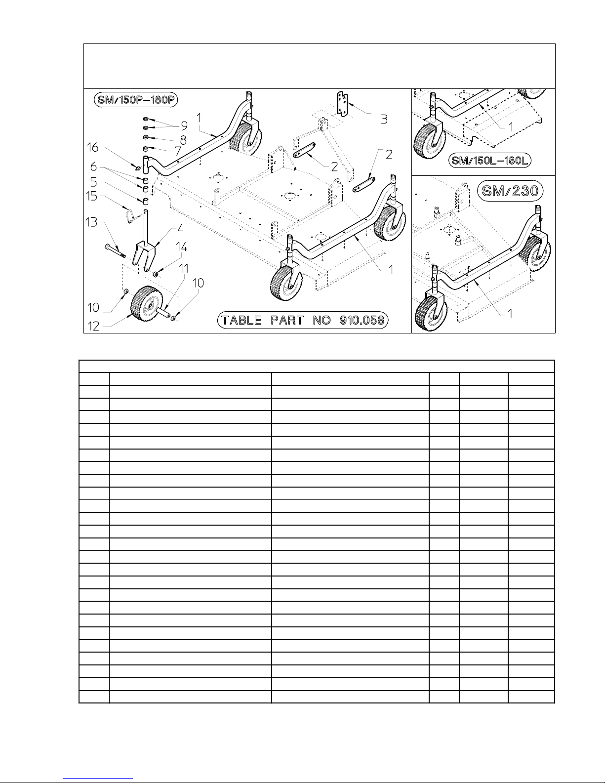
MOWERS WITH PNEUMATIC WHEEL
ITEM
DESCRIPTION
DESCRIPTION
Q.ty
PART NO
NOTE
1
WHEEL AXLE
ESSIEU ROUE
2
100.932
SM/150 P
1
WHEEL AXLE
ESSIEU ROUE
2
100.931
SM/180 P
1
WHEEL AXLE
ESSIEU ROUE
2
100.721
SM/230 P
1
WHEEL AXLE
ESSIEU ROUE
2
100.285
SM/150 L
1
WHEEL AXLE
ESSIEU ROUE
2
100.284
SM/180 L
2
SUPPORT
SUPPORT
2
100.297
3
HITCH
ATTELAGE
1
100.298
4
WHEEL SUPPORT
SUPPORT DE ROUE
4
100.291
5
SHIM ø1.2" x 1,26" (ø30,5x32 mm)
EPAISSEUR ø30,5x32 mm
4
100.145
6
SHIM ø1,2" x 1" (ø30,5x25 mm)
EPAISSEUR ø30,5x25 mm
8
100.144
7
SHIM ø1,2" x 0,47" (ø30,5x12 mm)
EPAISSEUR ø30,5x12 mm
4
100.143
8
SHIM ø1,2" x 0,24" (ø30,5x6 mm)
EPAISSEUR ø30,5x6 mm
4
100.142
9
SHIM ø1,2" x 0,08" (ø30,5x2 mm)
EPAISSEUR ø30,5x2 mm
8
100.141
10
SHIM
EPAISSEUR
8
100.338
11
SPACER
ENTRETOISE
4
100.339
12
WHEEL
ROUE
4
610.434
13
SCREW (M12x150)
VIS (M12x150)
4
610.271
14
NUT (M12-DIN 980)
ECROU (M12-DIN 980)
4
600.077
15
CLIP
GOUPILLE
4
610.466
16
GREASE NIPPLE M6
GRAISSEUR M6
4
600.124
*
COMPLETE WHEEL KIT AND ACCESSORIES GROUPE ROUE PNEUM. ET ACCESSORIES
1
100.933
SM/150 P
*
COMPLETE WHEEL KIT AND ACCESSORIES GROUPE ROUE PNEUM. ET ACCESSORIES
1
100.934
SM/180 P
*
COMPLETE WHEEL KIT AND ACCESSORIES GROUPE ROUE PNEUM. ET ACCESSORIES
1
100.935
SM/230 P
*
COMPLETE WHEEL KIT AND ACCESSORIES GROUPE ROUE PNEUM. ET ACCESSORIES
1
100.296
SM/150 L
*
COMPLETE WHEEL KIT AND ACCESSORIES GROUPE ROUE PNEUM. ET ACCESSORIES
1
100.295
SM/180 L
POUR LES AUTRES PIECES VOIR TABLES 910.055-910.056-910.065
FOR THE OTHER ITEMS SEE TABLE 910.055-910.056-910.065
MOWERS WITH PNEUMATIC WHEEL-TONDEUSE AVEC ROUE PNEUMATIQUE - TABLE PART NO 910.058
NOTE: ITEMS FOR THE PNEUMATIC WHEEL - PIECES POUR TONDEUSE PNEUMATIQUE

40
SOLID WHEEL KIT / KIT ROUES SOLIDE

41
SOLID WHEEL KIT FOR MOWERS -KIT ROUES SOLIDE POUR TONDEUSE - TABLE PART NO 910.063
ITEM DESCRIPTION DESCRIPTION Q.ty PART NO NOTE
1 WHEEL AXLE ESSIEU ROUE 2 110.068 SM/120 P
1 WHEEL AXLE ESSIEU ROUE 2 110.069 SM/150 P
1 WHEEL AXLE ESSIEU ROUE 2 100.699 SM/180 P
1 WHEEL AXLE ESSIEU ROUE 2 110.070 SM/230 P
1 WHEEL AXLE ESSIEU ROUE 2 100.207 SM/120 L
1 WHEEL AXLE ESSIEU ROUE 2 100.208 SM/150 L
1 WHEEL AXLE ESSIEU ROUE 2 100.209 SM/180 L
2 WHEEL SUPPORT SUPPORT DE ROUE 4 100.020 120-150-180
2 WHEEL SUPPORT SUPPORT DE ROUE 4 100.147 SM/230 P
3 SHIM ø1" x 1,26" (ø25,4x32 mm) EPAISSEUR ø25,4x32 mm 4 100.046 120-150-180
3 SHIM ø1.2" x 1,26" (ø30,5x32 mm) EPAISSEUR ø30,5x32 mm 4 100.145 SM/230 P
4 SHIM ø1" x 1" (ø25,4x25 mm) EPAISSEUR ø25,4x25 mm 4 100.045 120-150-180
4 SHIM ø1,2" x 1" (ø30,5x25 mm) EPAISSEUR ø30,5x25 mm 4 100.144 SM/230 P
5 SHIM ø1" x 0,47" (ø25,4x12 mm) EPAISSEUR ø25,4x12 mm 4 100.044 120-150-180
5 SHIM ø1,2" x 0,47" (ø30,5x12 mm) EPAISSEUR ø30,5x12 mm 4 100.143 SM/230 P
6 SHIM ø1" x 0,24" (ø25,4x6 mm) EPAISSEUR ø25,4x6 mm 4 100.043 120-150-180
6 SHIM ø1,2" x 0,24" (ø30,5x6 mm) EPAISSEUR ø30,5x6 mm 4 100.142 SM/230 P
7 SHIM ø1" x 0,08" (ø25,4x2 mm) EPAISSEUR ø25,4x2 mm 4 100.042 120-150-180
7 SHIM ø1,2" x 0,08" (ø30,5x2 mm) EPAISSEUR ø30,5x2 mm 4 100.141 SM/230 P
8 SHIM EPAISSEUR 8 100.006
9 SPACER ENTRETOISE 4 100.008
10 WHEEL ROUE 4 600.165
11 SCREW (M12x110) VIS (M12x110) 4 600.156
12 NUT (M12-DIN 980) ECROU (M12-DIN 980) 4 600.077
13 CLIP GOUPILLE 4 600.116
14 GREASE NIPPLE M6 GRAISSEUR M6 4 600.124
*
COMPLETE SOLIDE WHEEL KIT AND ACCESSORIESKIT ROUES SOLIDE ET ACCESSORIES
1 110.130 SM/120 P
*
COMPLETE SOLIDE WHEEL KIT AND ACCESSORIESKIT ROUES SOLIDE ET ACCESSORIES
1 110.203 SM/150 P
*
COMPLETE SOLIDE WHEEL KIT AND ACCESSORIESKIT ROUES SOLIDE ET ACCESSORIES
1 110.204 SM/180 P
*
COMPLETE SOLIDE WHEEL KIT AND ACCESSORIESKIT ROUES SOLIDE ET ACCESSORIES
1 110.133 SM/230 P
*
COMPLETE SOLIDE WHEEL KIT AND ACCESSORIESKIT ROUES SOLIDE ET ACCESSORIES
1 100.290 SM/120 L
*
COMPLETE SOLIDE WHEEL KIT AND ACCESSORIESKIT ROUES SOLIDE ET ACCESSORIES
1 100.289 SM/150 L
*
COMPLETE SOLIDE WHEEL KIT AND ACCESSORIESKIT ROUES SOLIDE ET ACCESSORIES
1 100.288 SM/180 L

42

43
ITEM
DESCRIPTION
DESCRIPTION
Q.ty
PART NO
NOTE
1
WHEEL SUPPORT
SUPPORT DE ROUE
1
100.020
120-150-180
1
WHEEL SUPPORT
SUPPORT DE ROUE
1
100.047
SM/230 P
2
SHIM
EPAISSEUR
2
100.006
3
SPACER
ENTRETOISE
1
100.008
4
WHEEL
ROUE
1
600.165
5
SCREW (M12x110)
VIS (M12x110)
1
600.156
6
NUT (M12-DIN 980)
ECROU (M12-DIN 980)
1
600.077
7
SHIM ø1" x 1,26" (ø25,4x32 mm)
EPAISSEUR ø25,4x32 mm
1
100.046
120-150-180
7
SHIM ø1.2" x 1,26" (ø30,5x32 mm)
EPAISSEUR ø30,5x32 mm
1
100.145
SM/230 P
8
SHIM ø1" x 1" (ø25,4x25 mm)
EPAISSEUR ø25,4x25 mm
2
100.045
120-150-180
8
SHIM ø1,2" x 1" (ø30,5x25 mm)
EPAISSEUR ø30,5x25 mm
2
100.144
SM/230 P
9
SHIM ø1" x 0,47" (ø25,4x12 mm)
EPAISSEUR ø25,4x12 mm
1
100.044
120-150-180
9
SHIM ø1,2" x 0,47" (ø30,5x12 mm)
EPAISSEUR ø30,5x12 mm
1
100.143
SM/230 P
10
SHIM ø1" x 0,24" (ø25,4x6 mm)
EPAISSEUR ø25,4x6 mm
1
100.043
120-150-180
10
SHIM ø1,2" x 0,24" (ø30,5x6 mm)
EPAISSEUR ø30,5x6 mm
1
100.142
SM/230 P
11
SHIM ø1" x 0,08" (ø25,4x2 mm)
EPAISSEUR ø25,4x2 mm
2
100.042
120-150-180
11
SHIM ø1,2" x 0,08" (ø30,5x2 mm)
EPAISSEUR ø30,5x2 mm
2
100.141
SM/230 P
12
SPLIT PIN ø8
GOUPILLE ø8
1
600.116
*
S
OLID WHEEL SUPPORT AND ACCESSORIES
G
ROUPE ROUES SOLIDE ET ACCESSORIES
1
110.213
120-150-180
*
SOLID WHEEL SUPPORT AND ACCESSORIES
G
ROUPE ROUES SOLIDE ET ACCESSORIES
1
110.214
SM/230 P
ITEM DESCRIPTION DESCRIPTION Q.ty PART NO NOTE
1 WHEEL SUPPORT SUPPORT DE ROUE 1 100.291
3 SHIM EPAISSEUR 2 100.338
3 SPACER ENTRETOISE 1 100.339
4 WHEEL ROUE 1 610.434
5 SCREW (M12x150) VIS (M12x150) 1 610.271
6 NUT (M12-DIN 980) ECROU (M12-DIN 980) 1 600.077
7 SHIM ø1.2" x 1,26" (ø30,5x32 mm) EPAISSEUR ø30,5x32 mm 1 100.145
8 SHIM ø1,2" x 1" (ø30,5x25 mm) EPAISSEUR ø30,5x25 mm 2 100.144
9 SHIM ø1,2" x 0,47" (ø30,5x12 mm) EPAISSEUR ø30,5x12 mm 1 100.143
10 SHIM ø1,2" x 0,24" (ø30,5x6 mm) EPAISSEUR ø30,5x6 mm 1 100.142
11 SHIM ø1,2" x 0,08" (ø30,5x2 mm) EPAISSEUR ø30,5x2 mm 2 100.141
12 SPLIT PIN ø8 GOUPILLE ø8 1 600.116
*
PNEUMATIC WHEEL SUPPORT AND ACCESSORIES ROUES PNEUMATIQUE ET ACCESSORIES
1 100.580
ITEM DESCRIPTION DESCRIPTION Q.ty PART NO NOTE
1 WHEEL SUPPORT SUPPORT DE ROUE 1 100.020 120-150-180
1 WHEEL SUPPORT SUPPORT DE ROUE 1 100.147 SM/230 P
2 SHIM EPAISSEUR 2 100.006
3 SPACER ENTRETOISE 1 100.008
4 WHEEL ROUE 1 600.165
5 SCREW (M12x110) VIS (M12x110) 1 600.156
6 NUT (M12-DIN 980) ECROU (M12-DIN 980) 1 600.077
*
SOLID WHEEL SUPPORT GROUPE ROUES SOLIDE 1 110.206 120-150-180
*
SOLID WHEEL SUPPORT GROUPE ROUES SOLIDE 1 110.207 SM/230 P
ITEM DESCRIPTION DESCRIPTION Q.ty PART NO NOTE
1 WHEEL SUPPORT SUPPORT DE ROUE 1 100.291
3 SHIM EPAISSEUR 2 100.338
3 SPACER ENTRETOISE 1 100.339
4 WHEEL ROUE 1 610.434
5 SCREW (M12x150) VIS (M12x150) 1 610.271
6 NUT (M12-DIN 980) ECROU (M12-DIN 980) 1 600.077
*
PNEUMATIC WHEEL SUPPORT GROUPE ROUES PNEUMATIQUE
1 110.208
SOLID WHEEL SUPPORT - GROUPE ROUES SOLIDE (SM/120-150-180=110.205/SM/230=110.193)
PNEUMATIC WHEEL SUPPORT - GROUPE ROUES PNEUMATIQUE (SM/150-180-230=100.208)
S
OLID WHEEL SUPPORT AND ACCESORIES-GROUPE ROUES SOLIDE ET ACCESSORIES (SM/120-150-180=100.578/SM/230=110.030)
TABLE PART NO.910.066
PNEUMATIC WHEEL SUPPORT AND ACCESORIES-GROUPE ROUES PNEUMATIQUE ET ACCESSORIES (SM/150-180-230=100.580)
44
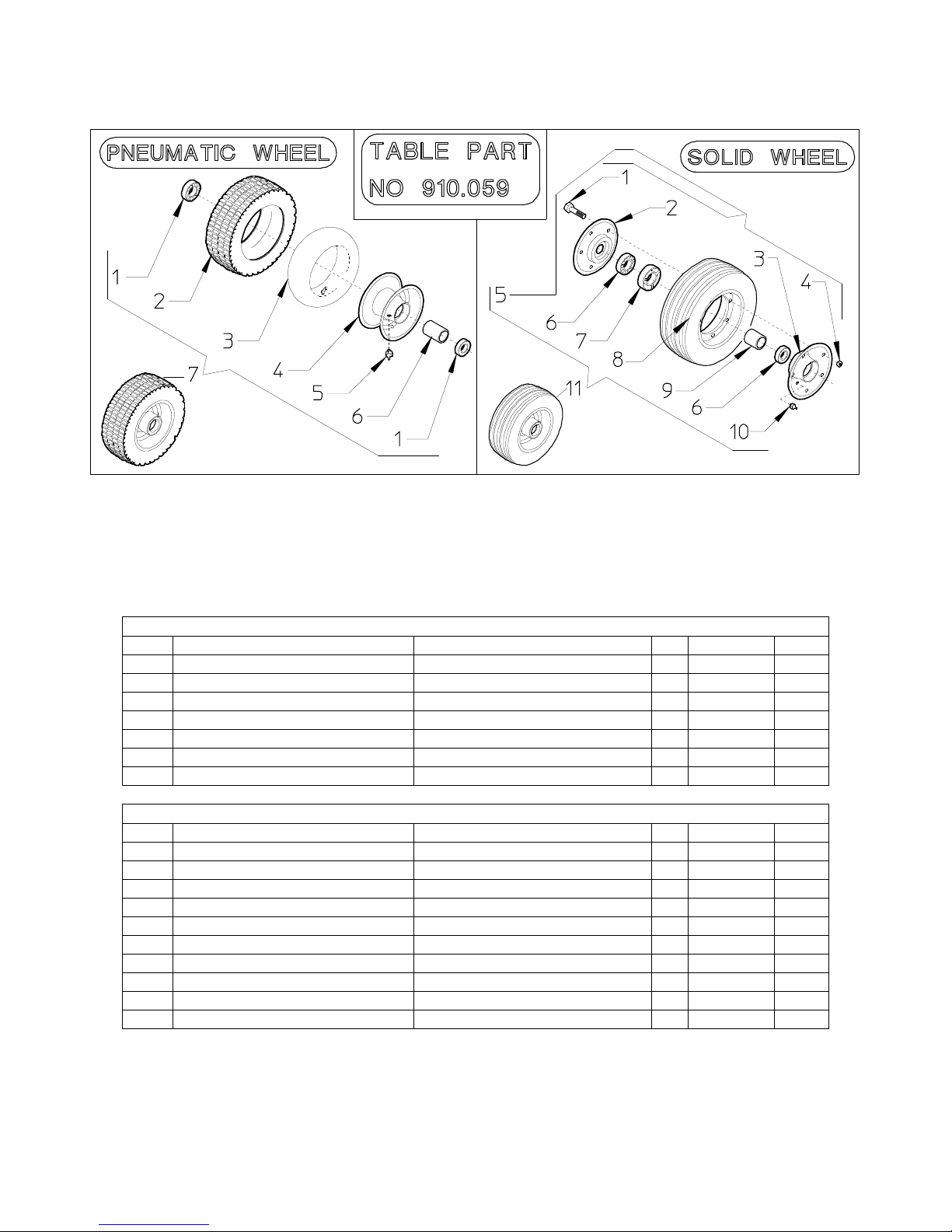
TABLE PART NO 910.059
PNEUMATIC WHHEL
ITEM DESCRIPTION DESCRIPTION Q.ty PART NO NOTE
1 BEARING 6005 Z PALIER 6005 Z 2 610.867
2 PNEU PENEU 1 610.321
3 TUBE CHAMBRE AD AIRE 1 610.315
4 RIM CIRCLE 1 610.468
5 GREASE NIPPLE M6 GRAISSEUR M6 1 600.124
6 SPACER ENTRETOISE 1 100.350
7 COMPLETE PNEU WHEEL ROUE PNEU COMPLETE 1 610.434
SOLID WHEEL
1 SCREW VIS 5 600.766
2 HALF RIM DEMI-CIRCLE 1 600.764
3 HALF RIM DEMI-CIRCLE 1 600.765
4 NUT (M8) ECROU (M8) 5 600.037
5 COMPLETE RIM CIRCLE COMPLET 1 620.680
6 BEARING 6205 Z PALIER 6205 Z 2 600.117
7 BUSH HAPPE 1 100.129
8 WHEEL ROUE 1 600.763
9 SPACER ENTRETOISE 1 100.128
10 GREASE NIPPLE M6 GRAISSEUR M6 1 600.124
11 COMPLETE SOLID WHEEL ROUE SOLIDE COMPLETE 1 600.165
45
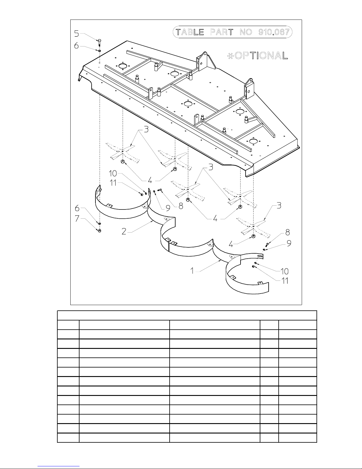
MULCHING KIT
ITEM DESCRIPTION DESCRIPTION Q.ty PART NO
1* RH CONVEYOR CONVOYEUR DROITE 1 100.739
2* LH CONVEYOR CONVOYEUR GAUCHE 1 100.740
3* BLADE LAME 5 100.358
4* NUT M16x1,5 ECROU M16x1,5 5 610.701
5* SCREW M10x25 VIS M10x25 10 600.006
6* WASHER ø10,5 RONDELLE ø10,5 20 600.322
7* NUT M10-DIN980 ECROU M10-DIN980 10 600.029
8* SCREW M8x20 VIS M8x20 2 600.223
9* WASHER ø8,5 RONDELLE ø8,5 2 600.115
10* LARGE WASHER ø8,5 RONDELLE LARGUE ø8,5 2 610.185
11* NUT M8-DIN980 ECROU M8-DIN980 2 600.076
* MULCHING KIT KIT MULCHING 1 100.735
TABLE PART NO 910.067
46
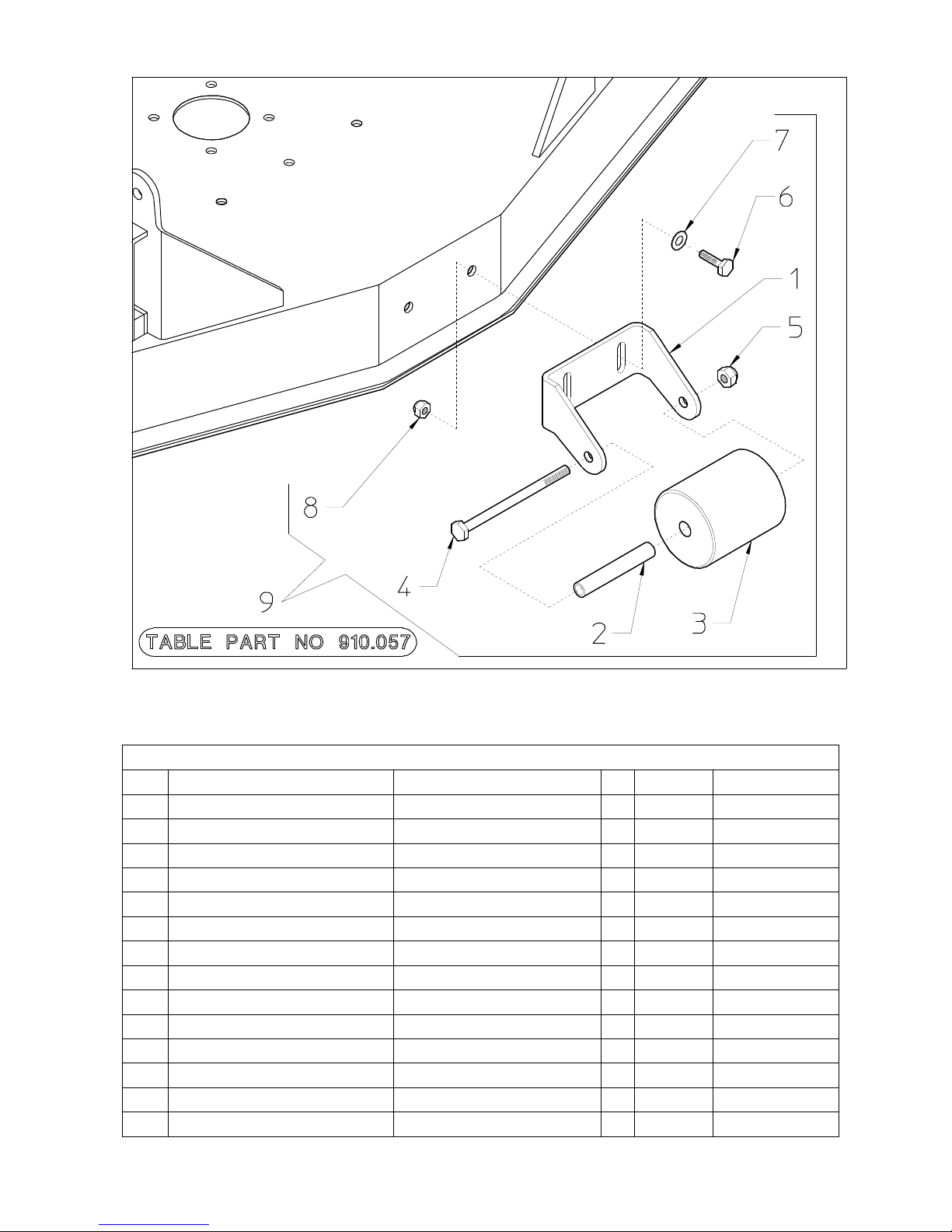
* OPTIONAL
TABLE PART NO 910.057
ITEM DESCRIPTION DESCRIPTION Q.ty PART NO NOTE
1 SUPPORT SUPPORT 1 100.258 SM/120-150-180
1 SUPPORT SUPPORT 1 100.263 SM/230
2 SPACER ENTRETOISE 1 100.259 SM/120-150-180
2 SPACER ENTRETOISE 1 100.504 230/P
3 ROLLER ROULEAU 1 100.260 SM/120-150-180
3 ROLLER ROULEAU 1 100.505 SM/230
4 SCREW (M12x160) VIS (M12x160) 1 600.807 SM/120-150-180
4 SCREW (M12x220) VIS (M12x220) 1 610.676 SM/230
5 NUT (M12-DIN 980) ECROU (M12-DIN 980) 1 600.077
6 SCREW (M10x25) VIS (M10x25) 2 600.006
7 WASHER ø10,5 RONDELLE ø10,5 2 600.322
8 NUT (M10-DIN 980) ECROU (M10-DIN 980) 2 600.029
9
ANTISCALPING KIT, COMPLETE GROUPE ROLEAU FRONTALE
1 100.364 SM/120-150-180
9
ANTISCALPING KIT, COMPLETE GROUPE ROLEAU FRONTALE
1 100.503 SM/230

47
GEARBOX / MULTIPLIER PART NO 100.273
ITEM Q.ty PART NO DESCRIPTION DESCRIPTION NOTE
1 4 600.054 SCREW (M10x25) VIS (M10x25)
2 1 600.346 GASCKET ø35-52x7 GARNITURE ø35-52x7
3 1 100.272 COVER BOUCHON
4 1 600.345 OR GASCKET JOINT
5 1 600.342 BEARING 6007 PALIER 6007
6 1 100.268 PTO SHAFT ARBRE
7 1 600.325 LATCH A10x8x30 CLAVETTE A10x8x30
8 1 100.269 CROWN Z34 COURONNE Z34
9 3 200.274 SHIM ø35,2x0,5 EPAISSEUR ø35,2x0,5
10 2 200.490 SHIM ø35,2x0,3 EPAISSEUR ø35,2x0,3
11 3 600.327 BEARING 6207 PALIER 6207
12 2 600.560 PLUG 3/8" BOUCHON 3/8"
13 1 600.328 CAP CAPSULE
14 1 100.267 GEARBOX BOITE
15 1 100.271 PINION Z12 PIGNON Z12
16 1 600.347 SPLIT PIN ø5x50 GOUPILLE ø5x50
17 1 100.270 SPACER ENTRETOISE
18 1 600.332 SNAP RING I 72 SEGMENT D'ARRET I 72
19 1 600.333 SNAP RING E 35 SEGMENT D'ARRET E 35
20 1 600.338 GASCKET ø35-72x10 GARNITURE ø35-72x10
21 1 600.337 RING SB 72 ANNEAU SB 72
22 1 600.335 WASHER ø25 RONDELLE ø25
23 1 600.296 NUT M24x2 ECROU M24x2

48
GEARBOX / MULTIPLIER PART NO 100.274
ITEM Q.ty PART NO DESCRIPTION DESCRIPTION NOTE
1 4 600.054 SCREW (M10x25) VIS (M10x25)
2 1 600.346 GASCKET ø35-52x7 GARNITURE ø35-52x7
3 1 100.272 COVER BOUCHON
4 1 600.345 OR GASCKET JOINT
5 1 600.342 BEARING 6007 PALIER 6007
6 1 100.268 PTO SHAFT ARBRE
7 1 600.325 LATCH A10x8x30 CLAVETTE A10x8x30
8 1 100.276 CROWN Z19 COURONNE Z19
9 3 200.274 SHIM ø35,2x0,5 EPAISSEUR ø35,2x0,5
10 2 200.490 SHIM ø35,2x0,3 EPAISSEUR ø35,2x0,3
11 3 600.327 BEARING 6207 PALIER 6207
12 2 600.560 PLUG 3/8" BOUCHON 3/8"
13 1 600.328 CAP CAPSULE
14 1 100.267 GEARBOX BOITE
15 1 100.277 PINION Z13 PIGNON Z13
16 1 600.347 SPLIT PIN ø5x50 GOUPILLE ø5x50
17 1 100.270 SPACER ENTRETOISE
18 1 600.332 SNAP RING I 72 SEGMENT D'ARRET I 72
19 1 600.333 SNAP RING E 35 SEGMENT D'ARRET E 35
20 1 600.338 GASCKET ø35-72x10 GARNITURE ø35-72x10
21 1 600.337 RING SB 72 ANNEAU SB 72
22 1 600.335 WASHER ø25 RONDELLE ø25
23 1 600.296 NUT M24x2 ECROU M24x2

49
GEARBOX / MULTIPLIER PART NO 100.275
ITEM Q.ty PART NO DESCRIPTION DESCRIPTION NOTE
1 4 600.054 SCREW (M10x25) VIS (M10x25)
2 1 600.346 GASCKET ø35-52x7 GARNITURE ø35-52x7
3 1 100.272 COVER BOUCHON
4 1 600.345 OR GASCKET JOINT
5 1 600.342 BEARING 6007 PALIER 6007
6 1 100.279 PTO SHAFT WITH PINION Z14 ARBRE AVEC PINION Z 14
7 1 600.325 LATCH A10x8x30 CLAVETTE A10x8x30
8 1 100.278 CROWN Z19 COURONNE Z19
9 3 200.274 SHIM ø35,2x0,5 EPAISSEUR ø35,2x0,5
10 2 200.490 SHIM ø35,2x0,3 EPAISSEUR ø35,2x0,3
11 3 600.327 BEARING 6207 PALIER 6207
12 2 600.560 PLUG 3/8" BOUCHON 3/8"
13 1 600.328 CAP CAPSULE
14 1 100.267 GEARBOX BOITE
15 1 100.304 SHAFT ARBRE
16 1 600.347 SPLIT PIN ø5x50 GOUPILLE ø5x50
17 1 100.270 SPACER ENTRETOISE
18 1 600.332 SNAP RING I 72 SEGMENT D'ARRET I 72
19 1 600.333 SNAP RING E 35 SEGMENT D'ARRET E 35
20 1 600.338 GASCKET ø35-72x10 GARNITURE ø35-72x10
21 1 600.337 RING SB 72 ANNEAU SB 72
22 1 600.335 WASHER ø25 RONDELLE ø25
23 1 600.296 NUT M24x2 ECROU M24x2
24 1 100.331 SHIM EPAISSEUR

50
GEARBOX / MULTIPLIER PART NO 100.299
ITEM Q.ty PART NO DESCRIPTION DESCRIPTION NOTE
1 4 600.054 SCREW (M10x25) VIS (M10x25)
3 1 100.303 COVER BOUCHON
4 1 600.345 OR GASCKET JOINT
5 1 600.342 BEARING 6007 PALIER 6007
6 1 100.302 PTO SHAFT ARBRE
7 1 600.325 LATCH A10x8x30 CLAVETTE A10x8x30
8 1 100.269 CROWN Z34 COURONNE Z34
9 3 200.274 SHIM ø35,2x0,5 EPAISSEUR ø35,2x0,5
10 2 200.490 SHIM ø35,2x0,3 EPAISSEUR ø35,2x0,3
11 3 600.327 BEARING 6207 PALIER 6207
12 2 600.560 PLUG 3/8" BOUCHON 3/8"
13 1 600.346 GASCKET ø35-52x7 GARNITURE ø35-52x7
14 1 100.267 GEARBOX BOITE
15 1 100.271 SHAFT WITH PINION Z12 ARBRE AVEC PINION Z12
16 1 600.347 SPLIT PIN ø5x50 GOUPILLE ø5x50
17 1 100.270 SPACER ENTRETOISE
18 1 600.332 SNAP RING I 72 SEGMENT D'ARRET I 72
19 1 600.333 SNAP RING E 35 SEGMENT D'ARRET E 35
20 1 600.338 GASCKET ø35-72x10 GARNITURE ø35-72x10
21 1 600.337 RING SB 72 ANNEAU SB 72
22 1 600.335 WASHER ø25 RONDELLE ø25
23 1 600.296 NUT M24x2 ECROU M24x2
24 1 100.331 SHIM EPAISSEUR

51
GEARBOX / MULTIPLIER PART NO 100.300
ITEM Q.ty PART NO DESCRIPTION DESCRIPTION NOTE
1 4 600.054 SCREW (M10x25) VIS (M10x25)
3 1 100.303 COVER BOUCHON
4 1 600.345 OR GASCKET JOINT
5 1 600.342 BEARING 6007 PALIER 6007
6 1 100.302 PTO SHAFT ARBRE
7 1 600.325 LATCH A10x8x30 CLAVETTE A10x8x30
8 1 100.276 CROWN Z19 COURONNE Z19
9 3 200.274 SHIM ø35,2x0,5 EPAISSEUR ø35,2x0,5
10 2 200.490 SHIM ø35,2x0,3 EPAISSEUR ø35,2x0,3
11 3 600.327 BEARING 6207 PALIER 6207
12 2 600.560 PLUG 3/8" BOUCHON 3/8"
13 1 600.346 GASCKET ø35-52x7 GARNITURE ø35-52x7
14 1 100.267 GEARBOX BOITE
15 1 100.277 SHAFT WITH PINION Z13 ARBRE AVEC PINION Z13
16 1 600.347 SPLIT PIN ø5x50 GOUPILLE ø5x50
17 1 100.270 SPACER ENTRETOISE
18 1 600.332 SNAP RING I 72 SEGMENT D'ARRET I 72
19 1 600.333 SNAP RING E 35 SEGMENT D'ARRET E 35
20 1 600.338 GASCKET ø35-72x10 GARNITURE ø35-72x10
21 1 600.337 RING SB 72 ANNEAU SB 72
22 1 600.335 WASHER ø25 RONDELLE ø25
23 1 600.296 NUT M24x2 ECROU M24x2

52
GEARBOX / MULTIPLIER PART NO 100.301
ITEM Q.ty PART NO DESCRIPTION DESCRIPTION NOTE
1 4 600.054 SCREW (M10x25) VIS (M10x25)
3 1 100.303 COVER BOUCHON
4 1 600.345 OR GASCKET JOINT
5 1 600.342 BEARING 6007 PALIER 6007
6 1 100.314 SHAFT WITH PINION Z14 ARBRE AVEC PINION Z14
7 1 600.325 LATCH A10x8x30 CLAVETTE A10x8x30
8 1 100.278 CROWN Z19 COURONNE Z19
9 3 200.274 SHIM ø35,2x0,5 EPAISSEUR ø35,2x0,5
10 2 200.490 SHIM ø35,2x0,3 EPAISSEUR ø35,2x0,3
11 3 600.327 BEARING 6207 PALIER 6207
12 2 600.560 PLUG 3/8" BOUCHON 3/8"
13 1 600.346 GASCKET ø35-52x7 GARNITURE ø35-52x7
14 1 100.267 GEARBOX BOITE
15 1 100.304 SHAFT ARBRE
16 1 600.347 SPLIT PIN ø5x50 GOUPILLE ø5x50
17 1 100.270 SPACER ENTRETOISE
18 1 600.332 SNAP RING I 72 SEGMENT D'ARRET I 72
19 1 600.333 SNAP RING E 35 SEGMENT D'ARRET E 35
20 1 600.338 GASCKET ø35-72x10 GARNITURE ø35-72x10
21 1 600.337 RING SB 72 ANNEAU SB 72
22 1 600.335 WASHER ø25 RONDELLE ø25
23 1 600.296 NUT M24x2 ECROU M24x2
24 1 100.331 SHIM EPAISSEUR

53
CARDAN SHAFT E3 090 E PART NO 610.014
CARDAN SHAFT/ARBRE A CARDAN Part No. 610.014
Item
Part No.
Pos. Code
Q.ty DESCRIPTION DESCRIPTION
1
610.071
2
QUICK RELEASE YOKE 1 3/8" Z6
FOURCHE
2
610.070
2
CROSS JOURNAL SET
CROISILLION COMPLET
3
610.072
1
YOKE WITH OUTER TUBE
FOURCHE AVEC TUYAU EXT,
4
610.073
1
YOKE WITH INNER TUBE
FOURCHE AVEC TUYAU INT,
5
610.074
1
RING FOR OUTER TUBE
BAGUE EXT.
6
610.075
1
RING FOR INNER TUBE
BAGUE INT.
7
610.057
2
COMPLETE PUSH BUTTON
POUSSOIR COMPLET
8
610.076
1
OUTER HALF SHAFT-W ITHOUT GUARD
MOITIE ARBRE EXT.SANS PROT.
9
610.077
1
INNER HALF SHAFT-WITHOUT GUARD
MOITIE ARBRE INT.SANS PROT.
10
610.078
1
OUTER BEARING
FRETTE EXT.
11
610.079
1
INNER BEARING
FRETTE INT.
12
610.080
1
OUTER BASIC CONE
COIFFE COMPLETE EXT.
13
610.081
1
INNER BASIC CONE
COIFFE COMPLETE INT.
14
610.082
1
OUTER HALF GUARD
MOITIE PROTECTION EXT.
15
610.083
1
INNER HALF GUARD
MOITIE PROTECTION INT.
16
610.084
1
OUTER HALF SHAFT -WITH GUARD
MOITIE ARBRE EXT. AVEC PROT.
17
610.085
1
INNER HALF SHAFT -WITH GUARD
MOITIE ARBRE INT. AVEC PROT.
18
610.068
1
CHAIN
CHAINE
19
610.086
1
COMPLETE GUARD
PROTECTION

54
CARDAN SHAFT B3 090 B PART NO 610.326
CARDAN SHAFT/ARBRE A CARDAN Part No. 610.326
Item
Part No.
Pos. Code
Q.ty DESCRIPTION DESCRIPTION
1
610.057
2
COMPLETE PUSH BUTTON
POUSSOIR COMPLET
2
610.071
2
YOKE
FOURCHE
3
610.070
2
CROSS JOURNAL ASS.
CROISILLION COMPLET
4
610.205
8
CIRCLIP
BAGUE
5
610.206
2
GREASE NIPPLE
GRAISSEUR
6
610.207
1
OUTER TUBE YOKE
FOURCHE TUYAU EXT.
7
610.208
1
FLEXIBLE PIN
GOUPILLE
8
610.209
1
CM. CARDAN TUBE
TUYAU CARDAN
9
610.210
1
CM. CARDAN TUBE
TUYAU CARDAN
10
610.211
1
FLEXIBLE PIN
GOUPILLE
11
610.212
1
INNER TUBE YOKE
FOURCHE TUYAU INTERIEUR
12
610.341
1
HALF SHAFT (WITHOUT GUARD)
MOITIE ARBRE EXT.SANS PROT.
13
610.412
1
HALF SHAFT (WITHOUT GUARD)
MOITIE ARBRE INT.SANS PROT.
14
610.345
1
HALF SAFETY GUARD
MOITIE PROTECTION EXT.
15
610.346
1
HALF SAFETY GUARD
MOITIE PROTECTION INT.
16
610.343
1
HALF SHAFT (WITH GUARD)
MOITIE ARBRE EXT.AVEC PROT.
17
610.416
1
HALF SHAFT (WITH GUARD)
MOITIE ARBRE INT.AVEC PROT.
18
610.414
1
O. BEARING
FRETTE
19
610.415
1
I. BEARING
FRETTE
20
610.080
1
O. BASIC CONE
COIFFE COMPLETE EXT.
21
610.081
1
I. BASIC CONE
COIFFE COMPLETE INT.
22
610.338
1
CM. SAFETY TUBE
TUYAU PROTECTION EXT.
23
610.339
1
CM. SAFETY TUBE
TUYAU PROTECTION INT.
24
610.068
2
CHAIN
CHAINE
25
610.347
1
SAFETY GUARD
PROTECTION

55

56
Zona Industriale-Viale Grecia, 8
06018 TRESTINA-(Perugia)-ITALY
Tel. +39.075.8540021-Telefax +39.075.8540523
e-mail: sitrex@sitrex.it www.sitrex.com
 Loading...