


S.p.A
OPERATOR'S MANUAL
SPARE PARTS LIST
RP/4-RP/5-RP/6-RP/8-RP/10-RP/12


TABLE OF CONTENT
1
MOUNTED SIDE-DELIVERY RAKES: RP/4-RP/5-RP/6-RP/8-RP/10-RP/12. ...................................... 2
1.1 INTRODUCTION .................................................................................................................................. 2
1.2 WARRANTEE ...................................................................................................................................... 2
1.3 CAUTION FOR USE ............................................................................................................................ 3
1.4 ASSEMBLY SOLUTION ...................................................................................................................... 3
1.5 SPECIFICATIONS ............................................................................................................................... 3
1.6 RP/4-RP/5 AND RP/6 RAKE ASSEMBLY INSTRUCTIONS ............................................................... 4
1.7 ASSEMBLING ...................................................................................................................................... 4
1.8 MOUNTING OF RP/4 AND RP/5 RAKE TO TRACTOR ..................................................................... 7
2
RP/8-RP/10 AND RP/12 V-RAKE ASSEMBLY INSTRUCTIONS.......................................................... 7
2.1 ASSEMBLING ...................................................................................................................................... 8
3
ON THE FIELD WITH RP/4-RP/5 AND RP/6 ......................................................................................... 9
3.1 RAKING..............................................................................................................................................10
3.2 SPREADING ......................................................................................................................................10
3.3 TURNING ...........................................................................................................................................10
4
ON THE FIELD WITH RP/8-RP/10 AND RP/12 V-RAKES ..................................................................11
5
FEATURES............................................................................................................................................12
6
MAINTENANCE ....................................................................................................................................12
7
Machine identification data and conformity declaration .................................................................12
8
SPARE PARTS LIST ........................................................................ Errore. Il segnalibro non è definito.
1

OPERATOR'S MANUAL
1
MOUNTED SIDE-DELIVERY RAKES:
RP/4-RP/5-RP/6-RP/8-RP/10-RP/12.
1.1 INTRODUCTION
This manual includes full instructions for a correct use and maintenance of the machinery, and the recommended spare parts list.
In order to prevent any possible damage of the machine and/or the operator(s) you are kindly requested to
go through this manual for a proper knowledge of the assembly of the implements, their use on the field, and
their maintenance. If any doubt, please contact your local dealer or distributor.
Should the machine be re-sold, you are kindly requested to supply this manual along with the machine to the
new purchaser.
1.2 WARRANTEE
The manufacturer warrants new machinery at the time of delivery to the original purchaser to be free from
defects in material and workmanship if properly set up and operated in accordance with this Operator's Manual.
The manufacturer undertakes to repair or replace free of charge any defective part which should be returned
by the purchaser (freight prepaid) and found to be defective by inspection authorized by the manufacturer
during the warranty period.
This warranty will be valid for 12 (twelve) months from the delivery of goods to the original purchaser.
In case the customer is not in a position to return the defectice part to the facturer, the manufacturer cannot
be held responsible for any cost due for repair or replacement of any part of the machine, he will only supply
the part(s) required for the repair and/or replacement.
The warranty is null and void when it is evident that the machine has been improperly used or repaired or
however repaired without authorization.
The manufacturer undertakes no responsibility for any obligation or agreement reached by any manufacturer
employers, agents or dealers, which are not in compliance with the above warranty. The manufacturer cannot be held responsible for the consequent damages. This warranty substitutes any other warranty, express
or implied, and any other manufacturer's obligation.
2

OPERATOR'S MANUAL
1.3 CAUTION FOR USE
It could be dangerous for people who are not familiar with this type of machine to use the rakes particularly
when kids are there during the assembly or operation on field. We therefore recommend the use of the only
to those people who are very familiar with the machine and the safety precautions.
1.4 ASSEMBLY SOLUTION
Our rakes are easily convertible into different sizes, as almost all parts are standard and interchangeable on
all sizes (wheel arms, wheels - etc.). With a special frame it is possible to attach together two RP/4-RP/5RP/6 rakes - R.H. and L.H. - and convert them into a V-rake.
Here are the advantages
1) Having a R.H. RP/4 rake or a R.H. RP/5 rake or a R.H. RP/6 rake you can convert them into a L.H.
RP/4 or L.H. RP/5 or L.H. RP/6 rake by replacing all wheel arms marked RIGHT with those marked
LEFT.
2) Having a R.H. RP/4 rake you can convert it into a RP/8 V-rake by attaching a L.H. RP/4 rake and the
relevant frame. To get one RP/10 V-rake from two RP/5 rake the procedure is still the same. To get
one RP/12 V-rake from two RP/6 rake the procedure is still the same.
3) You could also use your V-rake as two single ones, L.H. or R.H. rake, according to your requirements.
1.5 SPECIFICATIONS
MODELS
RP/4 RP/5 RP/6 RP/8 RP/10 RP/12
Weight
Number of wheels 4 5 6 8 10 12
Number of tines on each wheel 40 40 40 40 40 40
Wheel diam.
Raking working width
Turning and spreading working width
Transport width
Working speed
KW/HP required min.
180 Kg 200 Kg 250 Kg 460 Kg 520 Kg 620 Kg
396 lbs 440 lbs 551 lbs 1013 lbs 1146 lbs 1366 lbs
1,4 m 1,4 m 1,4 m 1,4 m 1,4 m 1,4 m
55" 55" 55" 55" 55" 55"
2,6 m 3,5 m 4,1 m 5,5 m 7,5 m 8,7 m
8' 6" 11" 6" 13' 6" 18' 1" 24' 7" 28' 6"
2,9 m 3,9 m 4,4 m 6,1 m 8,7 m 10 m
9' 6" 12' 10" 14' 5" 20' 28' 7" 32' 10"
2,2 m 2,3 m 2,3 m 3,6 m 4,7 m 4,7 m
7' 3" 7' 6" 7' 6" 11' 10" 15' 5" 15' 5"
22 kmh 22 kmh 22 kmh 22 kmh 22 kmh 22 kmh
14 mph 14 mph 14 mph 14 mph 14 mph 14 mph
22 Kw 22 Kw 22Kw 30 Kw 30Kw 30Kw
30 HP 30 HP 30HP 40HP 40HP 40HP
3
OPERATOR'S MANUAL
1.1
1.2
1.6 RP/4-RP/5 AND RP/6 RAKE ASSEMBLY INSTRUCTIONS
To room in the container we supply the partly knocked down. Here be-assembly instructions. For refer to
the enclosed breakdown.
1.7 ASSEMBLING
1.7.1
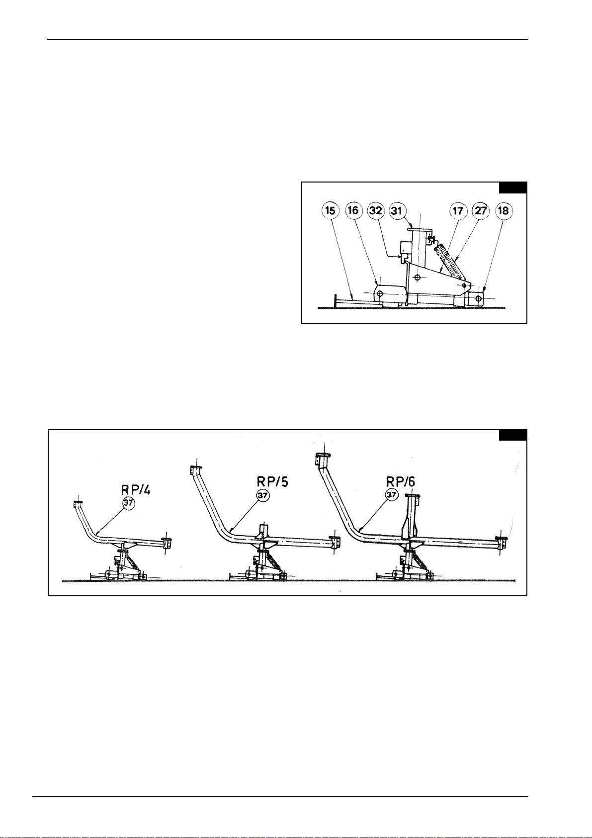
Position the parking stand (15) in its housing and
lock it with the pin (13), Next, lay the primary structure assembled) on the ground with the pipe (31)
upwards (pict 1.1).
1.7.2
Slide the pipe (37) into the swinging pipe (31) and retain with the supplied lever (33) and pin (36), so that it is
on axe with the three point hitch (pict. 1.2).
4
OPERATOR'S MANUAL
1.3
1.4
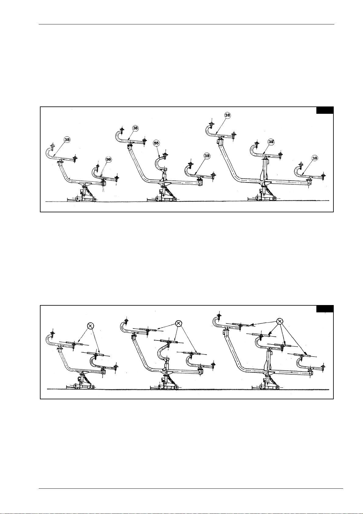
1.7.3
Attach the wheel arms (38) and lock them to the main pipe (37) with pins (36), so that they are on axe with
the main pipe (37). For the RP/5 rake, attach also the central arm (55) to the main pipe (37) and retain with
bolts (53-54-30) (pict. 1.3)
1.7.4
Attach the two central wheels (RP/4) or the three central wheels (RP/5) or the four central wheels (RP/6) to
the supplied arm flanges (38-55) and both them with the supplied bolts (pict. 1.4). when bolting the wheels
(x) check that the tine clamps (48) are turned toward the hub.
5

OPERATOR'S MANUAL
1.5
1.6
1.7.5
Lift the wheels (x) from the ground until they are in the working position (pict. 1.5).
1.7.6
Unlock the primary structure with the supplied lever (33) and pin (36), turn it by 90 degrees and lock it again
with the same pin. Now the is properly positioned on the ground and you only have to attach the remaining
wheels as explained above.
The rake is now fully assembled and ready to be mounted to the tractor (pict. 1.6)
IMPORTANT !
Above are the infractions for the R.H. rake assembly. Please refer to the above
instructions also for the L.H. rake assembly. Most parts are interchangeable for
both rakes, only the specific parts are marked RIGHT or LEFT
6

OPERATOR'S MANUAL
1.7 1.8
1.8 MOUNTING OF RP/4 AND RP/5 RAKE TO TRACTOR
When the rake Is ready to be to the tractor (pict. 1.6) attach the to the pins on both of the primary structure
(16).
Next, attach the three to the cap (18) of the pin. Now lift the rake to its setting and for transport lock with the
pin (32) for no rake floating (pict. 1.7).
Retain the part (17) to the crossbar (16) with the pin (19) into hole 1 (pict. 3.1) of the above said crossbar.
Now turn the main, pipe (37) the to the vertical position for transport (pict. 1.8).
IMPORTANT !
Never operate the rake with the pin (32) in the locked position. The locked position is for transport only (pict. 1.7).
2
RP/8-RP/10 AND RP/12 V-RAKE ASSEMBLY INSTRUCTIONS
RP/8 and RP/10 and RP/12 V-rakes are made as follows:
- no 1 main frame (1) complete of hitches (4-12).
- no 1 R.H. RP/4 or RP/5 or RP/6 rake, duly assembled as above.
- no 1 L.H RP/4 or RP/5 or RP/6 rake, duly assembled as above.
IMPORTANT !
On the R.H. and L.H. RP/4 and RP/5 and RP/6 rakes only the wheel arms and the
wheels are specific, all other parts are interchangeable for both rakes. The specific parts are marked RIGHT (for the R.H. rake) and LEFT (for the L.H. rake).
7

OPERATOR'S MANUAL
2.1 2.2
2.3 2.4
2.1 ASSEMBLING
2.1.1
Attach the hitches (4-12) and relevant counterplates (5) to both ends of the main frame (1) - in the position
show in picture 2.1 - with bolts (6-7-8) Attach hitches (4-12) to the opposite side of the tractor's hitches welded on the frame (1) (pict. 2.2).
2.1.2
Next, manually (pict, 2.3) or with a crane (pict. 2.4) lift the main frame (1) and bolt It to the tractor's lifting
arms.
8

OPERATOR'S MANUAL
2.5
3.1
2.1.3
Attach hitches (12) of frame (1) to the lateral pins welded on the primary structure (16) of rake with the pins
(11) the split pins (10). Attach the upper hitch (4) to the cap (18) the pin (9) and the split pin (10).
IMPORTANT !
For the V-rake transport please refer to the RP/4 and RP/5 and RP/6 rake
transport. Picture 2.5 below show the transport position of RP/8 and RP/10 and
RP/12 V-rakes.
3
ON THE FIELD WITH RP/4-RP/5 AND RP/6
Before operating the rake and after you have reached the field, unlock pin (32) (pict. 1.7 and relevant notes).
This will enable the rake to float independent of the main frame.
Next, adjust the rake working angle by positioning the pin (19) into the holes 2 to 7 (pict. 3.1). Hole 1 is for
transport only.
The rake is suitable for RAKING, SPREADING and TURNING as described below.
9

OPERATOR'S MANUAL
3.2
3.3
3.4
3.1 RAKING
(pict. 3.2) Turn the main
pipe (37) with the bend to
the left. Turn the wheel
arms (38) (on RP/5 turn
the wheel arm 55 as well)
with the bend to the left.
3.2 SPREADING
(pict. 3.3) Turn the main
pipe (37) with the bend to
the left.
Turn the wheel arms (38)
(on the RP/5 rake turn
the wheel arm 55 as well)
with the bend to the right.
3.3 TURNING
(pict. 3.4) Turn the main
pipe (37) with the bend to
the right. Turn the wheel
arms (38) (on RP/5 turn
the wheel arm 55 as well)
the bend to the left.
IMPORTANT !
Above we have described how to set a R.H. rake for the different operations. If
you to set a LH. rake for the above operations, please refer to pictures 3.2-3.4 of
V-rakes.
10

OPERATOR'S MANUAL
4.1
4.2
4
ON THE FIELD WITH RP/8-RP/10 AND RP/12 V-RAKES
RP/8 and RP/10 and RP/12 V-rakes are properly designed for windrowing, as ideal implement to complement the big balers. Slide the RP/4 or RP/5 or RP/6 on the frame (1) to get different working widths.
Below (pict. 4.1-4.2) the ideal positioning of the rake for a swath suitable for a 55 pick-up baler.
11

OPERATOR'S MANUAL
7.1
5
FEATURES
Our hayrakes are basically made of a primary structure of bent steel pipes, which make the Implement particularly sturdy and flexible. Tines are also very flexible, many are the possible adjustments of the rake, and
the implement can work fast and successfully even on slopes or on stony and rough soils. The wheel hubs
are made of pressed steel and are equipped with taper roller bearings, protected with a dust cover, so that
the wheels can properly turn.
6
MAINTENANCE
On our rakes no maintenance Is required. As a matter of fact no maintenance Is required for all gearings,
wheel hubs (equipped with 1st quality taper roller bearings and protected with a dust cover) and all setting
operations. No special tools are therefore required for servicing.
However, when the season is over, we recommend to clean the implement, to protect it from rust by oiling
and store it until next season.
IMPORTANT !
We recommend the use of our original spare parts only, to get your implement
working well for a long time. By ordering spare parts please always refer to the
parts breakdown provided with this manual.
Every our rake is provided with an identification label, as follows:
7
Machine identification data and conformity declaration
The machine is identified by means of the following technical data:
• Type of machine
• Registration number
• Year of manufacture
• Weight
stamped on the rating plate fastened to the frame of the machine. This data should be mentioned when requesting any replacements or information.
12

OPERATOR'S MANUAL
Have the wheels be turning
TROUBLES
1) Wheel does not unload
hay.
2) Tine failure.
3) The rake does not collect
the hay.
CAUSES
1) New tine, too much paint on it.
2) Mud on tine point due to moist
soil.
1) Going backwards with wheels
not lifted.
2) Too much pressure on the
wheels.
3) Tine rusted.
1) The wheel is too much inclined
to the ground.
2) Tine worn out.
REMEDIES
1)
on gravelly soil until the tine
is clean again.
2) The wheels are too close to
the ground.
1) Lift the wheels before going
backwards.
2) Lightly lift the rake.
3) Protect it by oiling.
1) By setting the 3rd point arm,
bring the wheel vertical to the
ground.
2) Replace it. We recommend
to replace all tines for uniform
height.
4) Too much floating of
wheels.
5) Bent tine.
1) Wheels too far from ground.
1) Going backwards with the
wheels not lifted.
2) Too much speed on rough soil.
3) Going across deep and narrow
ditches or prominences.
4) Too much weight on the
wheels.
1) Lightly lower the rake.
1) Lift the wheels when going
backwards
2) Reduce speed.
3) Reduce speed.
4) Lightly lift the rake.
13

OPERATOR'S MANUAL
14

ITEM
Q.ty
P ART NO
DESCRIP TION
NOTE
11200.055
RP /8 FRAME
22200.047
P IN
32600.017
SP LIT P IN
42200.056
UPP ER LINKAGE
56200.057
COUNTERP LATE
624600.001
SCREW M12x140
724600.018
SP R ING WASHER
824600.008
NUT
92200.058
3RD P OINT HITCH
1010600.019
SP LIT P IN
114200.059
P IN
124200.060
LOWER LINKAGE
134600.020
SP LIT P IN
142200.061
P ARKING STAND, FRAME
15
1(2)
200.062
P ARKING STAND, BASE
16
1(2)
210.369
BASE
17
1(2)
200.064
SUP P ORT
18
1(2)
200.065
CAP
19
1(2)
200.035
P IN
20
1(2)
200.067
P IN
21
2(4)
600.021
WASHER
22
2(4)
600.022
SP LIT P IN
23
1(2)
610.018
SCREW M14x120
24
1(2)
600.003
SCREW M14x100
25
1(2)
600.051
NUT
26
1(2)
200.068
UPP ER LINKAGE, SP RING
27
2(4)
200.069
SP R ING
28
1(2)
200.070
UPP ER LINKAGE, SP RING
29
1(2)
600.004
SCREW M12x30
30
1(2)
600.052
NUT
31
1(2)
200.071
SWINGING P IP E
32
1(2)
200.072
LOCK DEVIC E
33
3(6)
200.073
LEVER
34
6(12)
600.023
SNAP RING
35
3(6)
200.074
P IN
36
3(6)
200.075
P IN
37
1(2)
210.571
RP /4 MAIN P IPE
38
2(4)
200.077
WHEEL ARM, RH
38a
2(4)
200.078
WHEEL ARM, LH
39
4(8)
600.011
DUST COVER
40
4(8)
600.012
BEARING
41
4(8)
600.013
WHEEL HUB
42
4(8)
600.014
BEARING
43
4(8)
600.015
SELF LOCKING NUT
44
4(8)
600.016
SAFETY CAP
45
4(8)
200.010
FLANGE
46
4(8)
200.009
RIM
47
160/320
210.620
TINE DIA. 0,256" (6,5mm)
RP /4-RP /8 V
47
160/320
210.621
TINE DIA. 0,276" (7m m)
RP /4-RP /8 V
48
40(80)
200.012
TINE CAP
49
80(160)
600.005
SCREW
50
80(160)
600.029
NUT
51
24(48)
600.006
SCREW M10x25
52
24(48)
600.024
SP R ING WASHER
53
4(8)
205.277
P IN
54
24(48)
600.010
NUT
55
4(8)
600.301
SP LIT P IN
56
4(8)
205.041
HUB ASS Y
574210.180
WHEEL ASSY, RH
TINE DIA. 0,276" (7m m)
57a4210.181
WHEEL ASSY, LH
TINE DIA. 0,276" (7m m)
584210.182
WHEEL ASSY, RH
TINE DIA. 0,256" (6,5mm)
58a4210.183
WHEEL ASSY, LH
TINE DIA. 0,256" (6,5mm)
59
1(2)
600.075
NUT
TABLE P ART NO 920.255
15

16

ITEM
Q.ty
P ART NO
DESCRIPTION
NOTE
11200.081
RP /10 FR AME
22200.047
P IN
32600.017
SP LIT P IN
42200.056
UPP ER LINKAGE
56200.057
COUNTER P LATE
624600.001
SCREW M12x140
724600.018
SP RING WASHER
824600.008
NUT
92200.058
3RD P OINT HITCH
1010600.019
SP LIT P IN
114200.059
P IN
124200.060
LOWER LINKAGE
134600.020
SP LIT P IN
142200.061
P ARKING STAND, FRAME
15
1(2)
200.062
P ARKING STAND, BAS E
16
1(2)
210.369
BASE
17
1(2)
200.064
SUP P OR T
18
1(2)
200.065
CAP
19
1(2)
200.035
P IN
20
1(2)
200.067
P IN
21
2(4)
600.021
WASHER
22
2(4)
600.022
SP LIT P IN
23
1(2)
610.018
SCREW M14x120
24
1(2)
600.003
SCREW M14x100
25
1(2)
600.051
NUT
26
1(2)
200.068
UPP ER LINKAGE, SP RING
27
2(4)
200.069
SP RING
28
1(2)
200.070
UPP ER LINKAGE, SP RING
29
1(2)
600.004
SCREW M12x30
30
3(6)
600.052
NUT
31
1(2)
200.071
SWINGING P IP E
32
1(2)
200.072
LOCK DEVIC E
33
3(6)
200.073
LEVER
34
6(12)
600.023
SNAP RING
35
3(6)
200.074
P IN
36
3(6)
200.075
P IN
37
1(2)
210.199
RP /5 MAIN P IPE
38
2(4)
200.077
WHEEL ARM, RH
38a
2(4)
200.078
WHEEL ARM, LH
39
5(10)
600.011
DUST COVER
40
5(10)
600.012
BEARING
41
5(10)
600.013
WHEEL HUB
42
5(10)
600.014
BEARING
43
5(10)
600.015
SELF LOCKING NUT
44
5(10)
600.016
SAF ETY CAP
45
5(10)
200.010
FLANGE
46
5(10)
200.009
RIM
47
200/400
210.620
TINE DIA. 0,256" (6,5mm )
RP /5-RP /10 V
47
200/400
210.621
TINE DIA. 0,276" (7mm)
RP /5-RP /10 V
48
50(100)
200.012
TINE CAP
49
100(200)
600.005
SCREW
50
100(200)
600.029
NUT
51
30(60)
600.006
SCREW M10x25
52
30(60)
600.024
SP RING WASHER
53
2(4)
600.007
SCREW M12x85
54
2(4)
600.018
SP RING WASHER
551200.079
ARM, RH
55a1200.080
ARM, LH
56
5(10)
205.277
P IN
57
5(10)
600.301
SP LIT P IN
58
30(60)
600.010
NUT
59
4(8)
600.075
NUT
60
5(10)
205.041
HUB ASSY
615210.180
WHEEL ASSY, RH
TINE DIA. 0,276" (7mm)
615210.181
WHEEL ASSY, LH
TINE DIA. 0,276" (7mm)
625210.182
WHEEL ASSY, RH
TINE DIA. 0,256" (6,5mm )
625210.183
WHEEL ASSY, LH
TINE DIA. 0,256" (6,5mm )
63
1(2)
210.198
RP /5 P IPE
64
3(6)
600.310
SCREW M14x40
TABLE P ART NO 920.254
17

18

ITEM
Q.ty
PART NO
DESCRIPTION
NOTE
11200.081
FRAME
22200.047
PIN
32600.017
SPLIT PIN
42200.056
UPPER LINKAGE
56200.057
COUNTERPLATE
624600.001
SCREW M12x140
724600.018
SPRING WASHER ø13 DIN 127B
824600.008
NUT M12
92200.058
PIN
1011600.019
SPLIT PIN
114200.059
PIN
124200.060
LOWER LINKAGE
134600.020
SPLIT PIN
142200.061
PARKING STAND, FRAME
15
1(2)
230.163
PARKING STAND, BASE
16
1(2)
210.376
BASE
17
1(2)
230.202
SUPPORT
18
1(2)
200.094
CAP
19
1(2)
200.035
PIN
20
1(2)
230.203
PIN
21
1(2)
600.245
WAHER ø25
22
1(2)
600.725
NUT M24
23
1(2)
610.018
SCREW M14x120 DIN 931 8.8
24
1(2)
600.003
SCREW M14x100 DIN 931 8.8
25
1(2)
600.051
NUT M14
26
1(2)
200.121
UPPER LINKAGE, SPRING
27
2(4)
300.015
SPRING
28
1(2)
200.122
LOWER LINKAGE, SPRING
29
1(2)
600.004
SCREW M12x30 DIN 933 8.8
30
1(2)
600.052
NUT M12 DIN 934
31
1(2)
230.171
SWINGING PIPE
32
1(2)
200.072
LOCK DEVICE
33
4(8)
200.073
LEVER
34
8(16)
600.023
SNAP RING E 15 DIN 471
35
4(8)
200.074
PIN
36
4(8)
200.075
PIN
37
1(2)
210.612
MAIN PIPE
38
3(6)
200.077
RH WHEEL ARM
38a
3(6)
200.078
LH WHEEL ARM
39
6(12)
600.011
DUST COVER
40
6(12)
600.012
BEARING 30205
41
6(12)
600.013
WHEEL HUB
42
6(12)
600.014
BEARING 30204
43
6(12)
600.015
NUT M18x1,5
44
6(12)
600.016
SAFETY CAP
45
6(12)
200.010
FLANGE
46
6(12)
200.009
RIM
47
240(480)
210.620
TINE ø0,256"-6,5 mm
47
240(480)
210.621
TINE ø0,276"-7 mm
48
60(120)
200.012
TINE CLAMP
49
120(240)
600.005
SCREW M10x25 DIN 603 6.8
50
120(240)
600.029
NUT M10 DIN 980
51
60(120)
600.006
SCREW M10x25 DIN 933 8.8
52
60(120)
600.024
SPRING WASHER ø10,5 DIN 127B
53
6(12)
205.277
PIN
54
6(12)
600.301
SPLIT PIN
55
1(2)
600.075
NUT M14 DIN 980
56
60(120)
600.010
NUT M10 DIN 934
57
6(12)
205.041
HUB ASSY
58
3(6)
210.180
RH WHEEL ASSY (TINE ø0,276")
58
3(6)
210.181
LH WHEEL ASSY (TINE ø0,276")
59
3(6)
210.182
RH WHEEL ASSY (TINE ø0,256")
59
3(6)
210.183
LH WHEEL ASSY (TINE ø0,256")
60
1(2)
210.613
PIPE
61
3(6)
600.310
SCREW M14x40 DIN 933 8.8
62
3(6)
600.075
NUT M14 DIN 980
63
1(2)
620.629
SPRING PIN ø8x55
64
4(8)
600.808
BUSH
65
1(2)
600.034
GREASE NIPPLE M8
TABLE PART NO 920.248
19

20

ITEM
Q.ty
P ART NO
DESCRIP TION
NOTE
11210.575
P IP E
22600.020
SP LIT P IN
33600.075
NUT M14 DIN 980
41200.064
SUP P ORT
51200.067
P IN
62600.021
WASHER D.23 DIN 125A
72600.022
SP LIT P IN
81200.222
P IN
95600.019
SP LIT P IN
101610.018
SCREW M14x120 DIN 931 8.8
111210.369
BASE
123600.310
SCREW M14x40 DIN 933 8.8
131200.062
P ARKING STAND
141600.004
SCREW M12x30 DIN 933 8.8
151600.008
NUT M12 DIN 934-8
161200.068
UPP ER LINKAGE
172200.069
SP RING
181200.071
SWINGING P IPE
191200.070
LOWER LINKAGE, SP RING
201200.072
LOWER DEVICE
214200.073
LEVER
228600.023
SNAP RING E15 DIN 471
234200.074
P IN
244200.075
P IN
251210.576
MAIN P IP E
262200.077
WHEEL ARM, RH
272200.078
WHEEL ARM, LH
281210.067
ARM
291200.065
CAP
305205.277
P IN
315600.011
DUST COVER
325600.012
BEARING 30205
335600.013
WHEEL HUB
345600.014
BEARING 30204
355600.015
SELF LOCKING NUT M18x1.5-6
365600.301
SP LIT P IN
375600.016
SAFETY CAP
385205.041
HUB ASSY
3930600.006
SCREW M10x25 DIN 933 8.8
4030600.024
SP RING WASHER D 10.5
4130600.010
NUT M10 DIN 934-8
42
100
600.005
SCREW
4350200.012
TINE CLAMP
445200.010
FLANGE
45
100
600.029
NUT M10 DIN 980
465200.009
RIM
47
200
210.620
TINE DIA. 0,256" (6,5mm)
47
200
210.621
TINE DIA. 0,276" (7mm)
485210.180
WHEEL ASSY, RH
TINE DIA. 0,276" (7mm)
485210.181
WHEEL ASSY, LH
TINE DIA. 0,276" (7mm)
495210.182
WHEEL ASSY, RH
TINE DIA. 0,256" (6,5mm)
495210.183
WHEEL ASSY, LH
TINE DIA. 0,256" (6,5mm)
501600.003
SCREW M14x100 DIN 931 8.8
511600.051
NUT M14 DIN 934
TABLE P ART NO 920.146
21

22
Zona Industriale-Viale Grecia, 8
06018 TRESTINA-(Perugia)-ITALY
Tel. +39.075.8540021-Telefax +39.075.8540523
e-mail: sitrex@sitrex.it www.sitrex.com
 Loading...