

Page 1

A.I.S. RADAR RECEIVER
USER INSTRUCTIONS
Page 2

Software Updates
1. For convenience, channel selection has now been moved to the
Threshold Screen.
2. Alternate A and B channel switching has been included (A, B, A,
B…)
3. To reduce the waiting time for ship names they are now stored in
memory.
4. The selection of the user’s position on screen has been
simplified. Selection is now made by pressing CONFIG, then
CENTRE.
INTRODUCTION
The AIS radar consists of a dual frequency receiver, a powerful
computer and a high contrast display.
Vessels carrying AIS transponders are plotted directly onto the AIS
radar display. The tracks of each vessel show the true relative movement
of all targets in the display.
The receiver is designed to o perate from a 12 volt supply and requires a
conventional marine VHF antenna (not supplied) and an input from a
GPS receiver to give the user’s position.
INSTALLING THE DISPLAY
The AIS receiver is not waterproof and should only be cabin mounted.
Select a convenient position for the display on a panel or bulkhead. The
site must be flat and the cavity behind the panel must remain dry at all
times. Cut a hole in the panel 103mm by 143mm wide.
Unscrew the wing nut from the rear of the receiver and take off the
mounting clamp. Fit the ‘O’ ring in the groove on the rear and place the
unit in the hole in the panel. Refit the mounting clamp and finger tighten
the wing nut. Alternatively a cradle mounting kit is available where
panel mounting is impractical.
Plug the power cable into the rear of the receiver and connect to 12 volts.
(The red wire to positive and the wire with the black stripe to negative.
The unit is protected against reverse polarity.)
2
Page 3
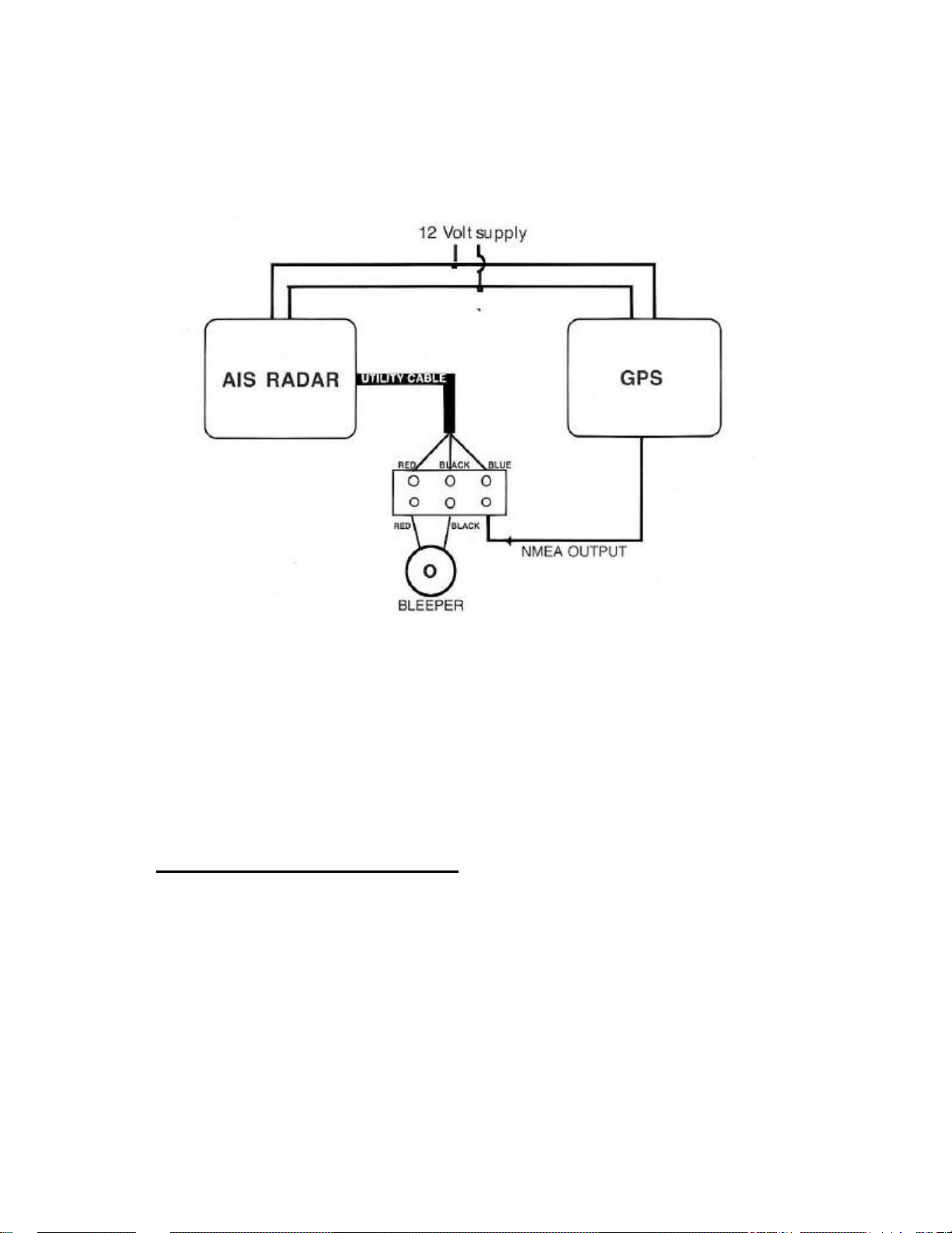
Plug in the UTILITY cable supplied and, using the terminal block,
connect as follows.
Connect the NMEA output (for NMEA+) of the GPS to the BLUE
wire of the UTILITY cable. If the GPS has a NMEA – or NMEA
REF connect this wire to the vessel supply negative. The AIS radar
requires an NMEA 0183 signal with RMC sentence. The signal
level must swing above and below 2 volts.
INSTALLING THE ANTENNA
The receiver requires its own marine VHF antenna and cannot be shared
with a transceiver antenna. It should be mounted as high as possible to
maximize range but should be spaced not less than 1 metre from a
transmitting antenna. The antenna cable should be at least 3 metres long
and the antenna should be sited at least 2 metres from the AIS receiver.
3
Page 4

SET UP PROCEDURE
The setup procedure allows the user to:
1/ Set the receiver sensitivity threshold.
2/ Set the display contrast.
3/ Select the source of user position (from GPS or memory).
4/ Select the AIS channel (A or B)
5/ Select the screen update rate (8, 15, 30 or 60 seconds).
Once selected, these settings are held in a non volatile memory.
FROM THE INTRODUCTION SCREEN
Select SETUP
1/ TO SET THRESHOLD: -select THRESHOLD.
A horizontal bar indicates the strength of the received signal. When
viewed ‘on air’ the bar will start from a minimum position near the left
of the screen and will rapidly shoot to the right of the screen as the short
bursts of AIS signals are received. Using the RAISE and LOWER
controls move the threshold setting bar until it is 1 or 2 stops above the
minimum of the signal strength bar.
2/ TO SET THE CONTRAST: - select CONTRAST.
Use LIGHTER and DARKER to set the desired contrast.
4
Page 5

3/ TO SET POSITION SOURCE: -select CONFIG then POS’N.
The screen now shows the position source.
To change:- select GPS to use the GPS position or press STORED to
use the previously stored position. Press BACK to return to the previous
page.
To store a new position:- with GPS connected select STORED then
press SAVE.
4/ TO SELECT AIS CHANNEL:- select CONFIG.
Pressing A/B will alternate between the two channels. The display
shows which channel is selected.
5/ TO SELECT THE SCREEN UPDATE RATE: - select CONFIG.
Pressing UPDATE rosters through the update rate (8, 15, 30, and 60
seconds.) The display shows what update rate is selected.
USING THE AIS RADAR
FROM THE INRODUCTION SCREEN:
Select LIST. This screen shows AIS data received in real time. The
data includes the ship’s MMSI number, navigation status symbol and its
latitude and longitude. It is this raw data that is used to plot on the radar
display. It is possible to FREEZE this data for closer inspection and
UNFREEZE it to return to normal.
The navigational status symbol shows the vessel’s current status. A
complete list of these symbols can be seen by pressing ICONS from the
introduction screen.
5
Page 6

Select RADAR to plot all the AIS targets on a simulated radar screen.
Pressing ZOOM followed by IN or OUT will change the scale.
The radius of the outer ring can be set to 1, 2, 4, 8, 16 or 32 nautical
miles. The selected scale is shown in the data box on the right of the
screen. Pressing OK gets out of the zoom option.
As well as plotting the most recent positions of a vessel the display
shows the last sixteen positions. This leaves a trail on the screen whose
length and direction represent the speed and direction of the vessel
relative to the user. The length of the track is also dependant on the
screen update rate. For example, if the update rate is set to 15 seconds
then a vessel will not have moved very far befo re the next position is
plotted so the track will be short. If the update rate is 30 seconds the
vessel will have moved twice as far each time the screen updates, so the
track will be twice as long.
For reference a sample vessel is shown in the data box (just below the
scale) together with its relative speed.
The AIS radar can track up to 24 vessels. If there are more than 24
vessels in range it will select the 24 nearest the user.
To select a vessel as a target press DATA. The closest vessel will be
selected and the target symbol will appear on that vessel. Selecting
NEXT or PREVIOUS will roster through all the vessels in range order.
When the desired vessel is selected its AIS data will be printed in the
data box on the next transmission. (The time taken to receive the
information will depend on how frequently the vessel transmits an
update.)
6
Page 7

From the radar screen selecting OPTIONS then TRACKS puts the unit
in time lapse mode. This is best appreciated when stationary. The
display will now plot tracks of vessels entering the screen until they
leave the screen. After a period of time (and this can be several hours) a
map of shipping routes will emerge.
NOTE – TRACKS WILL BUILD UP WHEN IN THE NORMAL
RADAR MODE BUT WILL CLEAR IF THE RANGE IS
CHANGED.
ADVANCED SETUP
It can be useful to place the user at a point other than the centre of the
screen. To do this select CONFIG then press BACK and UPDATE
simultaneously. Pressing NEXT will roster the centre through eight
off-centre positions. Pressing CENTRE will return to the centre.
Note – The selected range is represented by the second range ring.
TO SELECT THE ALARM
From the radar screen press ALARM to turn the alarm on or off. When
the alarm is active an alarm symbol is shown at the top right of the
screen. With alarm selected an audible alarm will sound when any AIS
carrying vessel is within the inner range ring on the radar screen.
7
Page 8

TROUBLESHOOTING
Q – The screen is completely blank.
A – Check power supply. It should be 12 volts with the centre pin of the
power plug positive.
Q – Signal strength bar remains at left of screen.
A – The unit is not receiving any AIS signals. Check VHF antenna.
Q – Signal strength bar is over to the right and hardly moving.
A – You are receiving some interference on that AIS channel. Switch off
all other equipment to isolate source of interference. Simple
changing the AIS channel may solve the problem.
Q – I cannot get good contrast on the display.
A – The unit needs at least 9 volts to operate the display properly. Check
the battery voltage.
Q – The unit says that no GPS is present.
A – Check that GPS has been set up to send NMEA data RMC sentence.
Q – A target vessel shows a heading of 511 degrees.
A – This is a default number signifying that no heading data is available.
Q – A vessel appears to be jumping back and forth between two
positions.
A – Probably two vessels with the same MMSI number. This should not
happen as a ship’s MMSI number is unique. Check the LIST, if two
vessels share the same number then inform the relevant authority.
8
Page 9

Notes
Page 10

Caution
Some vessels do not carry A.I.S.
It is important at all times to keep a proper lookout.
The A.I.S. radar is not a substitute for good seamanship.
Marine Electronics Inc.
11001 Roosevelt Blvd., Suite 800
St. Petersburg, FL 33716
Tel: 727-576-5734 • Fax: 727-570-8646
Web Site: www.si-tex.com
 Loading...