

Technical Data Sheet
ød
f7/h6
øD
3x20°
øZ
H8
X
+0,2
H1
H2
H
HL
3
0
°
6
x
6
0
°
L1
AG
G
AG
T2
ød
f7/h6
øD
3x20°
øZ
H8
X
+0,2
H1
H2
H
HL
3
0
°
6
x
6
0
°
L1
AG
G
AG
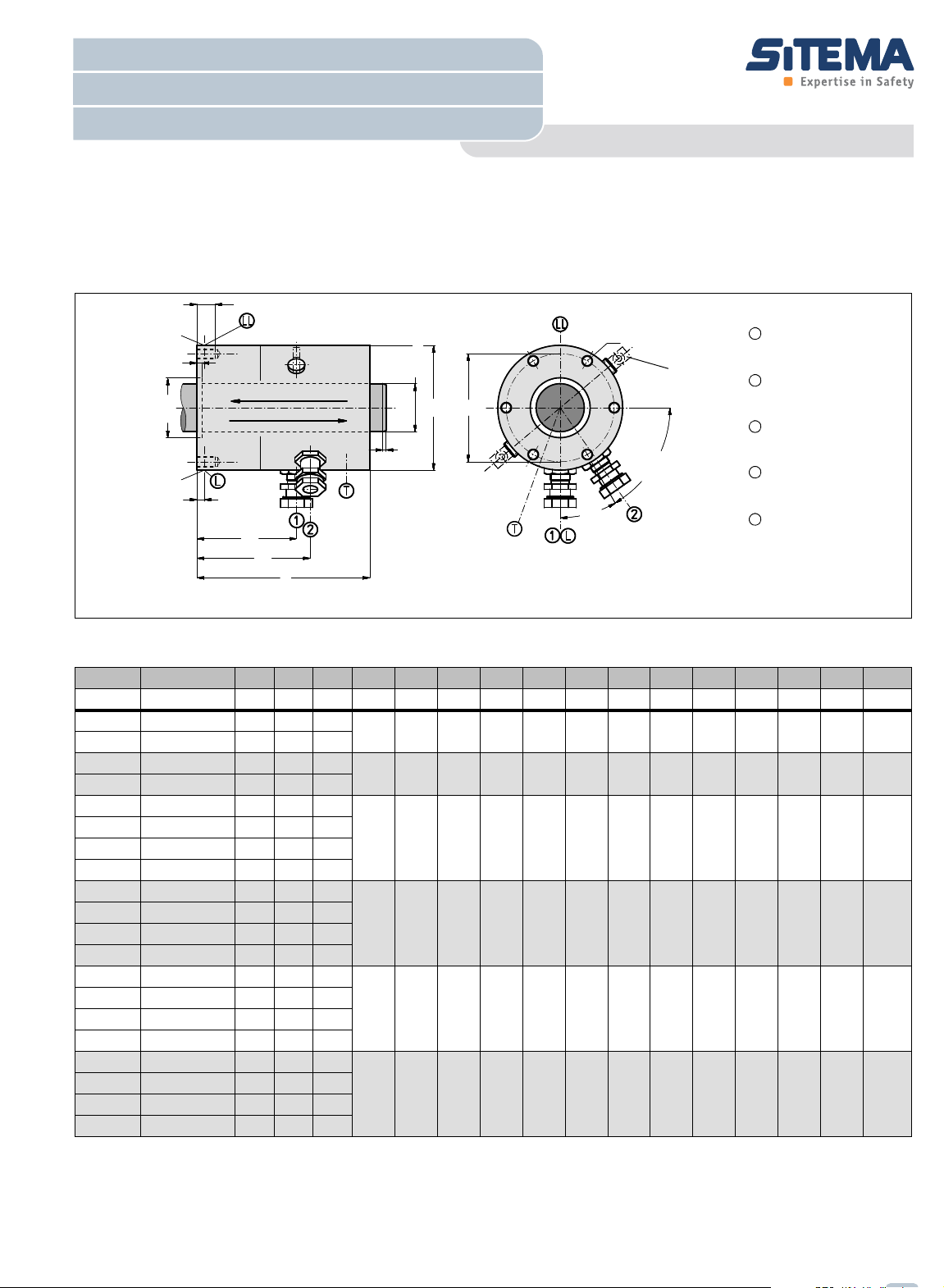
Port:
release pressure
see
1
Alternativ port:
release pressure
see
4
Port:
pressure compensation
Proximity switch port:1
Signal „clamped“
see
3
Proximity switch port:2
Signal „unclamped“
see
3
L
T
1
2
LL
Information for KFH 18 - KFH 60:
Due to tolerances ports 1 can be
displaced up to +/-4°
Load direction 1
Load direction 2
5
Rod diameter 18mm - 60mm
SITEMA - Locking Unit KFH
Locking by Spring Force / Hydraulic Releasing
English translation of German original
TI-F50-EN-08/2011
Technical Data Sheet TI-F50
Locking Unit KFH
For detailed functional description refer to„Technical Information TI-F10“. Furthermore important practical advices are
given in the „Operating Manual BA-F50“.
Fig. 1: Dimensions Locking Unit KFH ( CAD-Files download at www.sitema.com )
Type Ident.-No. d F p D H L1 T2 G Z X AG VL HL H1 H2 Weight
KFH 18
KFH 18
KFH 25
KFH 25
KFH 28
KFH 28
KFH 32
KFH 32
KFH 36
KFH 36
KFH 40
KFH 40
KFH 45
KFH 45
KFH 50
KFH 50
KFH 56
KFH 56
KFH 60
KFH 60
1 F is guaranteed as nominal (minimum) holding force for dry or mineral oil wetted shafts.
KFH 018 50
KFH 018 51
KFH 025 50
KFH 025 51
KFH 028 50
KFH 028 51
KFH 032 50
KFH 032 51
KFH 036 50
KFH 036 51
KFH 040 50
KFH 040 51
KFH 045 50
KFH 045 51
KFH 050 50
KFH 050 51
KFH 056 50
KFH 056 51
KFH 060 50
KFH 060 51
p is the pressure required for releasing. The permissible working pressure is 160 bar.
2 Hydraulic operating volume.
11 2
mm kN bar mm mm mm mm mm mm mm mm cm
18 10 70
18 5 40
25 20 100
25 12 50
70 122 60 12 M6 30 4 G1/8 6 23 88,5 96,5 3
95 140 82 15 M8 50 6 G1/8 12 21 89,5 83 7
28 40 100
28 20 50
32 40 100
115 178 96 18 M10 60 6 G1/4 23 20 118 112 13
32 20 50
36 50 100
36 35 55
40 50 100
138 200 115 18 M10 70 6 G1/4 28 19 109,5 119 18
40 35 55
45 75 100
45 45 75
50 75 100
50 45 75
56 100 100
56 70 70
60 100 100
155 213 135 20 M12 85 8 G1/4 43 20 147,5 140 26
180 228 160 20 M12 95 10 G1/4 62 22 151,5 144 36
60 70 70
3 Proximity switch holders are provided for standard proximity swit-
except KFH 18 and KFH 25: M8x1 with nominal distance 1,5 mm.
ches M12x1 shielded and with a nominal switching distance of 2 mm,
4 Plugged hydraulic port LL alternative to L, also usefull for bleeding.
5 Spacers are provided to keep released. To be removed after instal-
lation!
Subject to modification without prior notice
3
mm mm mm kg
Technical Data Sheet
ød
f7/h6
øD
3x20°
øZ
H8
X
+0,2
H1
H2
H
HL
3
0
°
6
x
6
0
°
L1
AG
G
AG
T1
ød
f7/h6
øD
3x20°
øZ
H8
X
+0,2
H1
H2
H
HL
3
0
°
6
x
6
0
°
L1
AG
G
AG
T2
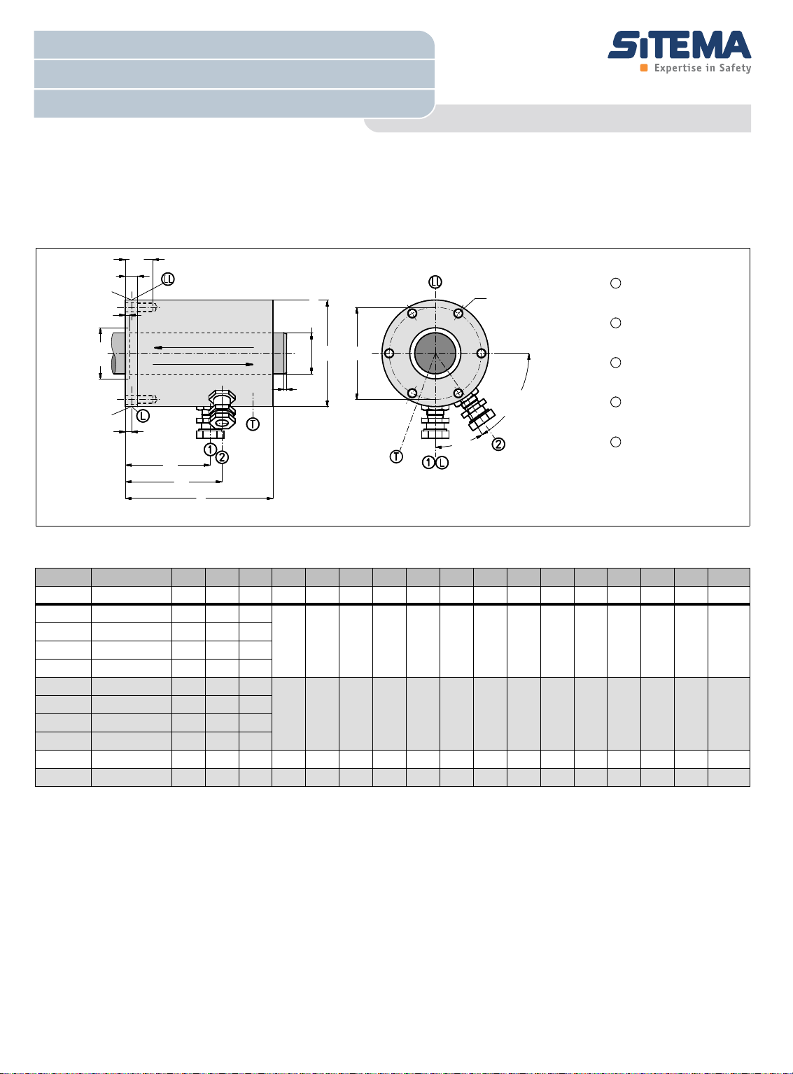
Port:
release pressure
see
1
Alternativ port:
release pressure
see
4
Port:
pressure compensation
Proximity switch port:1
Signal „clamped“
see
3
Proximity switch port:2
Signal „unclamped“
see
3
Direction of load 1
Direction of load 2
L
T
1
2
LL
Rod diameter 70mm - 140mm
SITEMA - Locking Unit KFH
Locking by Spring Force / Hydraulic Releasing
TI-F50-EN-08/2011
Technical Data Sheet TI-F50
Locking Unit KFH
For detailed functional description refer to„Technical Information TI-F10“. Furthermore important practical advices are
given in the „Operating Manual BA-F51“.
Fig. 2: Dimensions Locking Unit KFH ( CAD-Files download at www.sitema.com )
11 2
Type Ident.-No. d F p D H L1 T1 T2 G Z X AG VL HL H1 H2 Weight
3
mm mm mm kg
KFH 70
KFH 70
KFH 80
KFH 80
KFH 90
KFH 90
KFH 100
KFH 100
KFH 125
KFH 140
KFH 070 50
KFH 070 51
KFH 080 50
KFH 080 51
KFH 090 50
KFH 090 51
KFH 100 50
KFH 100 51
KFH 125 50
KFH 140 50
mm kN bar mm mm mm mm mm mm mm mm mm cm
70 150 100
70 80 60
80 150 100
225 302 195 26 56 M16 110 10 G1/4 86 13 192 185 79
80 80 60
90 250 130
90 190 100
100 250 130
260 360 225 30 65 M20 125 10 G3/8 100 15 221 214 118
100 190 100
125 330 100 350 405 300 40 90 M30 230 10 G3/8 220 26 244,5 235 225
140 600 100 430 514 370 50 95 M30 170 10 G3/8 250 30 346 334 458
Subject to modification without prior notice
1 F is guaranteed as nominal (minimum) holding force for dry or mineral oil wetted shafts.
p is the pressure required for releasing. The permissible working pressure is 160 bar.
2 Hydraulic operating volume.
3 Proximity switch holders are provided for standard proximity swit-
ches M12x1 shielded and with a nominal switching distance of 2 mm.
For easier service, the proximity switch holders have a positive stop
and are preset when deliverd from the factory.
4 Plugged hydraulic port LL alternative to L, also usefull for bleeding.

Technical Data Sheet
*)
**)
p
SITEMA - Locking Unit KFH
Locking by Spring Force / Hydraulic Releasing
TI-F50-EN-08/2011
Operational purpose
The Locking Device KFH clamps a shaft in any position. It is
commonly used on a cylinder rod or an other round shaft and
holds axial forces in both axial directions.
Load direction
A force in load dircetion 1 is always held without backlash
If the force acts in load direction 2 a backlash also does not oc-
cur, provided the force is not exceeding approx. 80% of the nominal holding force F. Otherwise the possible axial
displacement is 0.1 - 0.3 mm.
Choosing the right size
The table (Page1 and Page 2) shows the nominal holding force
F of the various items. The value F must be higher than the static load in the particular application.
In case a vertically moved mass is to be secured, a reasonable
safety factor must be applied by the designer. This factor depends on the kind of machinery, but shoudn't be less than 1.5.
If people have to be secured against dangers of lifted static
loads at the necessary regular testing must be performed with
at least 1.5 times the load.
T o guarantee the holding force during service even under unfavourable conditions, the actual holding force when new has to
be higher than the nominal holding force. It will not, however,
exceed twice the value. The fixing elements that absorb the
force (e.g. articulations for the holding rod) must therefore be
dimensioned for 2 x F.
In practice, suitable and commercially available rods are:
1. Piston rods, hard chrome plated (ISO tolerance f7)
Basic material: Yield strength, min. 580 N/mm²
Induction hardened HRC 56 - 64 / min. 1 mm deep
Hard chrome plating: 800-1100 HV min. 13 µm deep
Surface finish: RA 0,15 - 0,25
2. Shafts for linear ball bearings (ISO tolerance h6)
Induction hardened HRC > 60
Surface finish: RA 0,15 - 0,25
Pressure fluid
Hydraulic oil (HLP) in accordance with DIN 51524-2 must be
used as pressure medium. Please consult us before using any
other media.
Control
In most applications the actuation suggested in Abb.3 is used.
During every operational cycle the 3/2-way valve is actuated
electrically and releases the locking unit. In all other operational
conditions, as well as in cases of power failure, emergency
stop, etc. the locking unit becomes effective secures the rod
and stops the load. In case the pressure should fail, the load is
secured in the same way.
To avoid possible problems, the shaft should not be driven unless the proximity switch 2 indicates "unclamped".
T- port
The tapped hole marked T (tank, oil leakage) is used for pressure compensation (breathing). It is plugged with a filter e lement when supplied from the factory.
In case the Locking Unit KFH is to work in corrosive environment, e.g. coolant spray, port T must be connected to clean atmosphere or hydraulic tank by a pipe or hose
Rod material
The Locking Unit KFH will operate correctly only if the rod has
the correct surface:
• ISO tolerance field f7 or h6
• Surface roughness: Rz = 1 to 4 µm.
• Rod surface hardened (min HRC 56).
• Hardchrome plated surface recommended
• Lead-in chamfer 3x20°, rounded.
As the actual holding force can be as high as two times the nominal holding force F (for F see data sheets or dimensional drawing), care must be taken to ensure that the strength of rod
material is adequate. In the case of compression-loaded rods,
sufficient buckling resistance must be assured.
Fig. 3: Schematic diagramm of hydraulic circuit
* If impact noises are audible when pressuring the Locking Unit KFH
due to excess pressure, they can be suppressed by means of a flow
control valve in the p-line.
** If the pressure (p) is not suficiently constant (e.g. pressure drop at
the beginning of a downward stroke) we recommend a check valve
in the p-connection of the valve.
Under no circumstances may the hydraulic flow between connection L and the tank be impaired by any additional components.
If a particular quick response of the Locking Unit KFH is required, the following preconditions must be met:
• Short piping distances
• large valve and pipe cross-sections
• fast valve response times

Technical Data Sheet
SITEMA - Locking Unit KFH
Locking by Spring Force / Hydraulic Releasing
Operating conditions
The Locking Unit KFH is designed to operate in usual clean and
dry shop atmosphere.
In case of other environments at least the T-port for breathing
purposes is to be connected to a clen and dry volume (tank).
Should heavy soiling conditions (grinding dust, chips, other liquids, etc.) exist, please contact SITEMA.
Grease on the rod may reduce the holding force. T he permissible ambient temperature is 0 - 60°C.
Regular functional checks
The Locking Unit KFH must be functionally checked at regular
intervals. Regular checking is the only way to ensure that the
unit operate safely in the long run.
For applications in the field of personal safety (operater protection), testing must be carried out at least once every 6 months.
Depending on the relevant application parameters (soiling level, cycle time, control), significantly more frequent checks may
be advisable. In many cases, even (fully automatic) daily
checks may be necessary.
For testing a force at least equal to the working force, but normally equal to the nominal holding force F is applied.
In every case the criteria is, that the test force is held without
slipping.
TI-F50-EN-08/2011
Required risk assessment
It must be ensured that the dimensions and arrangement of
SITEMA - Safety Brakes in safety-relevant applications meet
the requirements of the risk evaluation DIN EN ISO 14121-1
and also comply with any further standards and regulations applying to the intended use. This is the duty of the system manufacturer and the user.
Maintenance
Maintenance is limited to the regular test of the holding force as
prescribed above.
The SITEMA - Locking Unit KFH is a safety element. Any repair
or refurbishing must be carried out by SITEMA. SITEMA cannot
take any responsibility for repairs by another party.
 Loading...