

SITEMA KFH 18, KFH 60, KFH 140 technology data
Technical Data Sheet
ød
f7/h6
øD
3x20°
øZ
H8
X
+0,2
H1
H2
H
HL
3
0
°
6
x
6
0
°
L1
AG
G
AG
T2
ød
f7/h6
øD
3x20°
øZ
H8
X
+0,2
H1
H2
H
HL
3
0
°
6
x
6
0
°
L1
AG
G
AG
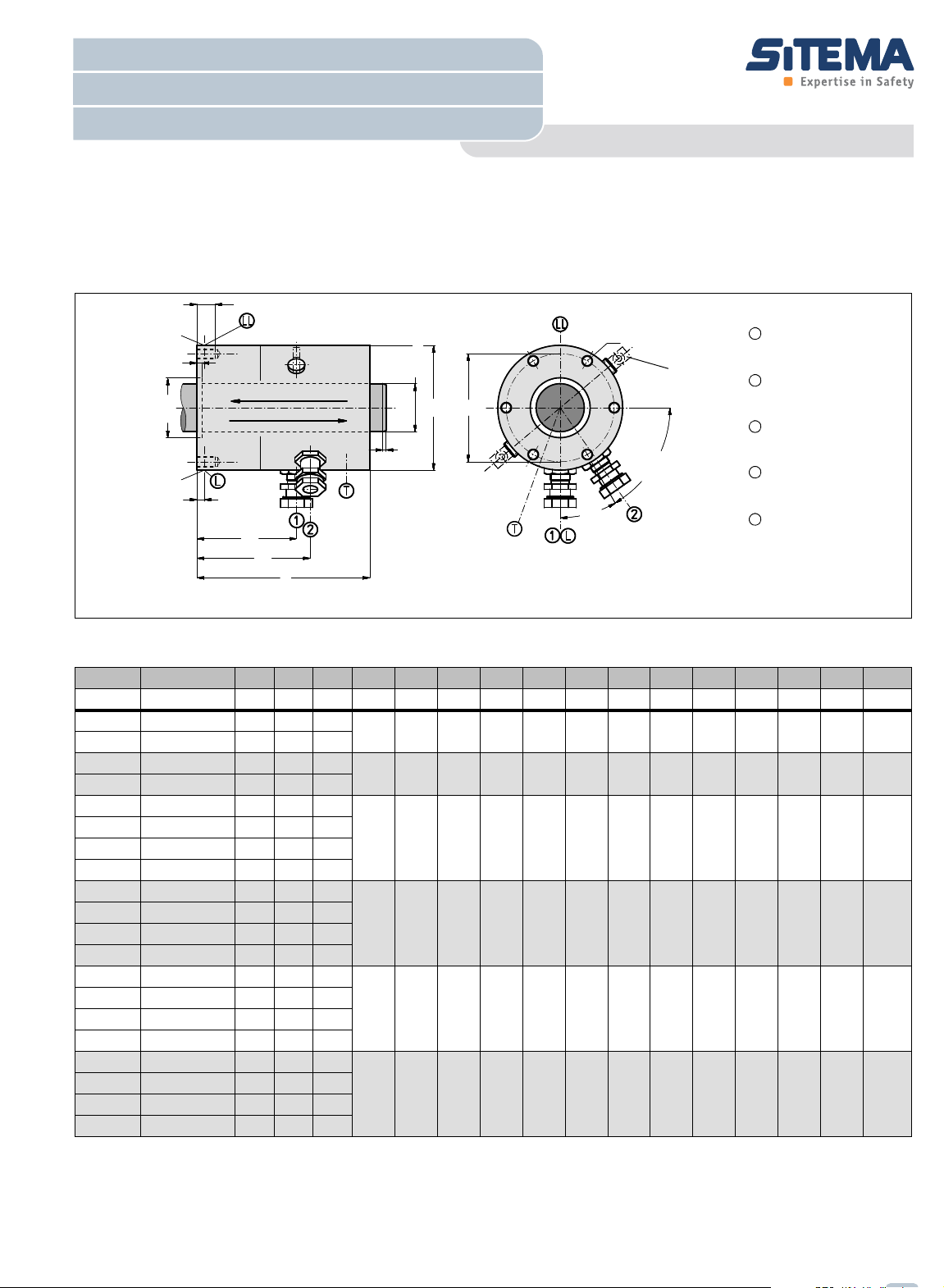
Port:
release pressure
see
1
Alternativ port:
release pressure
see
4
Port:
pressure compensation
Proximity switch port:1
Signal „clamped“
see
3
Proximity switch port:2
Signal „unclamped“
see
3
L
T
1
2
LL
Information for KFH 18 - KFH 60:
Due to tolerances ports 1 can be
displaced up to +/-4°
Load direction 1
Load direction 2
5
Rod diameter 18mm - 60mm
SITEMA - Locking Unit KFH
Locking by Spring Force / Hydraulic Releasing
English translation of German original
TI-F50-EN-08/2011
Technical Data Sheet TI-F50
Locking Unit KFH
For detailed functional description refer to„Technical Information TI-F10“. Furthermore important practical advices are
given in the „Operating Manual BA-F50“.
Fig. 1: Dimensions Locking Unit KFH ( CAD-Files download at www.sitema.com )
Type Ident.-No. d F p D H L1 T2 G Z X AG VL HL H1 H2 Weight
KFH 18
KFH 18
KFH 25
KFH 25
KFH 28
KFH 28
KFH 32
KFH 32
KFH 36
KFH 36
KFH 40
KFH 40
KFH 45
KFH 45
KFH 50
KFH 50
KFH 56
KFH 56
KFH 60
KFH 60
1 F is guaranteed as nominal (minimum) holding force for dry or mineral oil wetted shafts.
KFH 018 50
KFH 018 51
KFH 025 50
KFH 025 51
KFH 028 50
KFH 028 51
KFH 032 50
KFH 032 51
KFH 036 50
KFH 036 51
KFH 040 50
KFH 040 51
KFH 045 50
KFH 045 51
KFH 050 50
KFH 050 51
KFH 056 50
KFH 056 51
KFH 060 50
KFH 060 51
p is the pressure required for releasing. The permissible working pressure is 160 bar.
2 Hydraulic operating volume.
11 2
mm kN bar mm mm mm mm mm mm mm mm cm
18 10 70
18 5 40
25 20 100
25 12 50
70 122 60 12 M6 30 4 G1/8 6 23 88,5 96,5 3
95 140 82 15 M8 50 6 G1/8 12 21 89,5 83 7
28 40 100
28 20 50
32 40 100
115 178 96 18 M10 60 6 G1/4 23 20 118 112 13
32 20 50
36 50 100
36 35 55
40 50 100
138 200 115 18 M10 70 6 G1/4 28 19 109,5 119 18
40 35 55
45 75 100
45 45 75
50 75 100
50 45 75
56 100 100
56 70 70
60 100 100
155 213 135 20 M12 85 8 G1/4 43 20 147,5 140 26
180 228 160 20 M12 95 10 G1/4 62 22 151,5 144 36
60 70 70
3 Proximity switch holders are provided for standard proximity swit-
except KFH 18 and KFH 25: M8x1 with nominal distance 1,5 mm.
ches M12x1 shielded and with a nominal switching distance of 2 mm,
4 Plugged hydraulic port LL alternative to L, also usefull for bleeding.
5 Spacers are provided to keep released. To be removed after instal-
lation!
Subject to modification without prior notice
3
mm mm mm kg
Technical Data Sheet
ød
f7/h6
øD
3x20°
øZ
H8
X
+0,2
H1
H2
H
HL
3
0
°
6
x
6
0
°
L1
AG
G
AG
T1
ød
f7/h6
øD
3x20°
øZ
H8
X
+0,2
H1
H2
H
HL
3
0
°
6
x
6
0
°
L1
AG
G
AG
T2
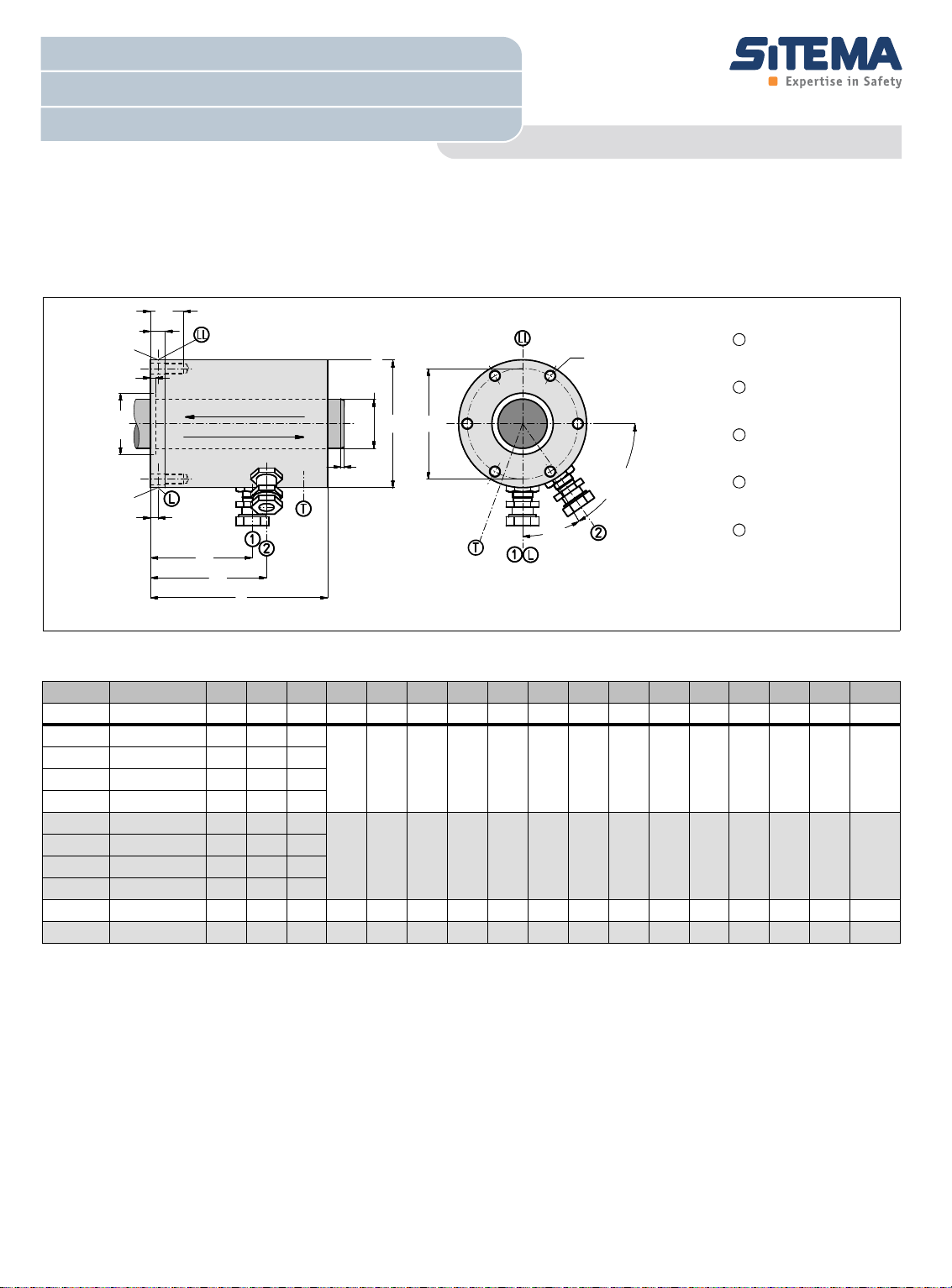
Port:
release pressure
see
1
Alternativ port:
release pressure
see
4
Port:
pressure compensation
Proximity switch port:1
Signal „clamped“
see
3
Proximity switch port:2
Signal „unclamped“
see
3
Direction of load 1
Direction of load 2
L
T
1
2
LL
Rod diameter 70mm - 140mm
SITEMA - Locking Unit KFH
Locking by Spring Force / Hydraulic Releasing
TI-F50-EN-08/2011
Technical Data Sheet TI-F50
Locking Unit KFH
For detailed functional description refer to„Technical Information TI-F10“. Furthermore important practical advices are
given in the „Operating Manual BA-F51“.
Fig. 2: Dimensions Locking Unit KFH ( CAD-Files download at www.sitema.com )
11 2
Type Ident.-No. d F p D H L1 T1 T2 G Z X AG VL HL H1 H2 Weight
3
mm mm mm kg
KFH 70
KFH 70
KFH 80
KFH 80
KFH 90
KFH 90
KFH 100
KFH 100
KFH 125
KFH 140
KFH 070 50
KFH 070 51
KFH 080 50
KFH 080 51
KFH 090 50
KFH 090 51
KFH 100 50
KFH 100 51
KFH 125 50
KFH 140 50
mm kN bar mm mm mm mm mm mm mm mm mm cm
70 150 100
70 80 60
80 150 100
225 302 195 26 56 M16 110 10 G1/4 86 13 192 185 79
80 80 60
90 250 130
90 190 100
100 250 130
260 360 225 30 65 M20 125 10 G3/8 100 15 221 214 118
100 190 100
125 330 100 350 405 300 40 90 M30 230 10 G3/8 220 26 244,5 235 225
140 600 100 430 514 370 50 95 M30 170 10 G3/8 250 30 346 334 458
Subject to modification without prior notice
1 F is guaranteed as nominal (minimum) holding force for dry or mineral oil wetted shafts.
p is the pressure required for releasing. The permissible working pressure is 160 bar.
2 Hydraulic operating volume.
3 Proximity switch holders are provided for standard proximity swit-
ches M12x1 shielded and with a nominal switching distance of 2 mm.
For easier service, the proximity switch holders have a positive stop
and are preset when deliverd from the factory.
4 Plugged hydraulic port LL alternative to L, also usefull for bleeding.
 Loading...