

Page 1
LN-521
1 | P a g e
Page 2

Table of Contents
1. Safety instructions ........................................................................................................................... 4
2 Introduction .......................................................................................................................................... 5
2.1 What exactly is Homeplug? ........................................................................................................... 5
Cost factor and transmission quality ............................................................................................... 5
Data security and radiation ............................................................................................................. 5
2.2 Package Contents .............................................................................................................................. 5
3. Introduction of the hardware .............................................................................................................. 6
4. Install the hardware ............................................................................................................................ 9
Application 1 – Link to remote DSL via Powerline............................................................................... 9
Application 2 – as wireless AP + Ethernet switch .............................................................................. 10
Application 3– multiple floor home networking ............................................................................... 11
Application 4–as Powerline Ethernet switch ..................................................................................... 12
Application 5 – Wireless AP w/ Router ............................................................................................. 13
5. Hardware Configuration .................................................................................................................... 14
5.1 Setting Wireless encryption by WPS button ............................................................................... 14
5.2 Create a private encrypted network ........................................................................................... 15
5.3 Add an extra Homeplug ............................................................................................................... 15
5.4 Remove a device from a network Group .................................................................................... 16
5.5 Make two public network devices private .................................................................................. 16
5.6 Standby Mode ............................................................................................................................. 16
7. Configuring the LN-521 via the GUI ................................................................................................... 17
LOGIN procedure ........................................................................................................................... 17
Basic ................................................................................................................................................... 19
Setup Wizard ................................................................................................................................. 19
System settings .............................................................................................................................. 20
Lan Settings ................................................................................................................................... 21
WiFi Settings .................................................................................................................................. 22
Advanced ........................................................................................................................................... 24
WiFi Advanced ............................................................................................................................... 24
WPS Settings .................................................................................................................................. 26
Management ..................................................................................................................................... 28
System Status ................................................................................................................................ 28
2 | P a g e
Page 3

PLC Settings ................................................................................................................................... 30
Save / Reload Settings ................................................................................................................... 31
Firmware Upgrade ......................................................................................................................... 32
Using the Utility ..................................................................................................................................... 33
Installation ......................................................................................................................................... 33
Configuring using the Utility .............................................................................................................. 40
Declaration of Conformity ..................................................................................................................... 42
3 | P a g e
Page 4

1. Safety instructions
All safety and operating instructions should be read and understood before using the device, and
should be kept for future reference.
• Never open the Homeplug adapter. There are no user-serviceable parts inside the
Homeplug adapter.
• Do not try to service this product yourself! Contact qualified technicians each and every
time your device needs maintenance. There is a risk of electric shock!
• Use the Homeplug adapter in a dry location only.
• Do not insert any objects into the openings of the Homeplug adapter.
• To disconnect the Homeplug adapter from the power supply grid, pull the power plug.
• Do not keep the Homeplug adapter in direct sunlight.
• Slots and openings on the case serve as ventilation. Never block or cover them.
• Never set up the Homeplug adapter near a heater or radiator.
• The Homeplug adapter should be located only where sufficient ventilation according to
the instructions of the manufacturer can be ensured.
• Disconnect the Homeplug adapter from the power supply grid before cleaning. Use a
moist towel to clean the device. Never use water, paint thinner, benzene, alcohol or
other strong cleaning agents when cleaning the device, as these could damage the case.
• Never use the Homeplug adapter with a power supply that does not meet the
specifications provided on the rating plate. If you do not know what type of power
supply you have at home, contact your dealer or energy supplier.
• In the event of damage, disconnect the Homeplug adapter from the power supply grid
and contact customer service. This applies, for example
o if the power cable or plug is damaged
o liquid has been spilled on the Homeplug adapter or objects have fallen into the
device.
o the Homeplug adapter has been exposed to rain or water.
o the Homeplug adapter does not work, even though the operating instructions
have been followed properly.
o the Homeplug adapter’s case is damaged.
4 | P a g e
Page 5

2 Introduction
In this chapter, we will provide an overview of the Homeplug technology and introduce it briefly.
2.1 What exactly is Homeplug?
Homeplug is home and office networking using the electric wiring already installed in the
building.
Cost factor and transmission quality
Homeplug is an economical and easy-to-use networking technology. You don't need to lay cables
and you can connect to the home network at every power point.
The Homeplug standard modulates and demodulates additional frequencies on the power lines.
Modulation and demodulation is a well-known and proven method of data transmission, which
has been in use in other applications for a number of years. Now it is used to set up Internet and
network accesses in the home or office. Depending on the damping factor, distances of at least
200 meters can be covered.
With a maximum data rate up to 500 Mbps and symmetrical upload and download speeds,
Homeplug is comparable to traditional Ethernet network solutions.
Data security and radiation
128-bit AES encryption is used, which guarantees secure data transfer within the network.
2.2 Package Contents
Open the package carefully, and make sure that none of the items listed below are missing. Do
not discard the packing materials, in case of return; the unit must be shipped back in its original
package.
• The Homeplug device.
• A CD containing manuals and utility
• A quick installation guide
• a CAT 5e Ethernet cable (1.5 meter)
5 | P a g e
Page 6
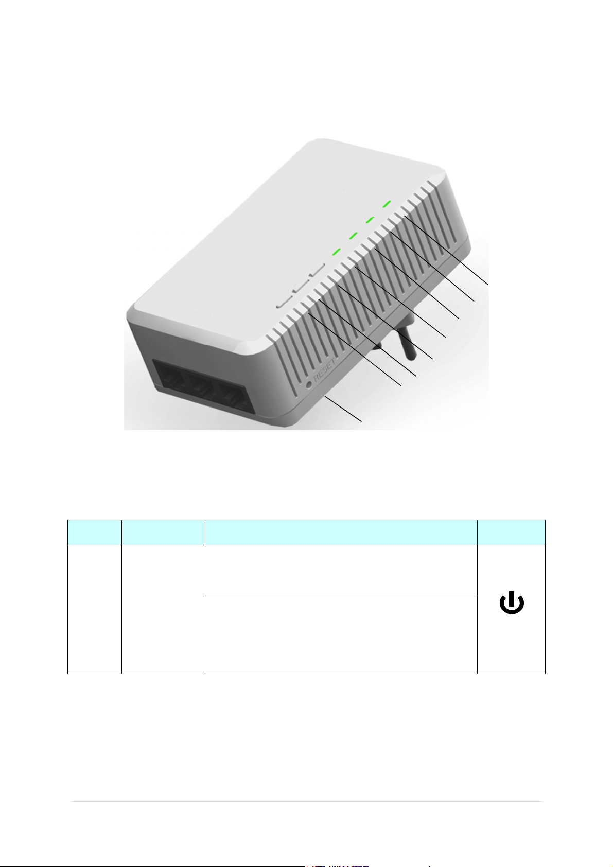
3. Introduction of the hardware
H
F
G
A
B
C
D
E
Table 1 - LED definition
position LED name Behavior Symbol
LED OFF –
Device Power off
POWER LED
A
LED fast blinking (0.5 sec ON / 0.5 sec OFF) –
Green color
This means the device is doing Security key exchange, the device
joining or being joined into same logical network will continue 2
minutes' blinking, until the procedure succeeds or is canceled.
6 | P a g e
Page 7

LED OFF –
Sole member (either other devices in same network is too far or it is
alone in its logical network).
LED solid ON –
HOMEPLUG Link detected but no traffic
HOMEPLUG
Link/Activity
B
LED
Green + Red
WiFi & Security
C
LED
a. Green: HOMEPLUG Physical data rate > 100Mbps
b. Green + Red: 40Mbps < HOMEPLUG Physical data rate <
100Mbps
c. Red: 0 < HOMEPLUG Physical data rate < 40Mbps
LED blinking (0.06 sec ON / 0.06 sec OFF)—
HOMEPLUG data traffic
a. Green: HOMEPLUG Physical data rate > 100Mbps
b. Green + Red: 40Mbps < HOMEPLUG Physical data rate <
100Mbp
c. Red: 0 < HOMEPLUG Physical data rate < 40Mbps
Steady Green: WiFi active under security protection,
Flash Green: WiFi transmits packets under security protection,
Steady Red: WiFi active under NO security protection,
D
Green + Red
Operation
mode LED,
Green + Red
Flash Red: WiFi transmits packets under NO security protection,
OFF: when WiFi is disabled
Green ON: When in router mode (factory default is AP Bridge mode)
Green OFF: Bridge (AP) mode.
Red Flash: WPS activity
Red OFF: No WPS activity
R
7 | P a g e
Page 8

Table 2 – push button definition
Position Push button name Behavior Symbol
Press 1 to 5 seconds – switch WiFi OFF/ON. Factory default is WiFi ON
E
F
G
WiFi Setting
button
WPS
GROUP/Pairing
Press > 5 seconds – switch Router mode ON /OFF. Factory default is OFF.
When pressing the button, the operation mode LED will flash once per
second. Please keep pressing for 5 LED ON-and-OFF, then release the
button after the LED fast blink with red color.
Press > 1.0 sec: start WPS procedure. during the WPS procedure, LED
blinks red for 2.5 minutes then stop automatically.
Press 1.5 to 4 seconds - start or stop Security key exchange
When press and release the button for 1.5 to 4.0 seconds, this will enter
Security key exchange procedure. In this procedure, the device starts
joining into a logical network of other device or announcing its network
for other devices to join. This procedure automatically stops after two
minutes or until user press this button 1.5 to 4 sec again.
Press over 10 seconds - Generate random security key
H
RESET
(inside the
needle pin hole)
When continuous press is or over 10 sec, all LED light OFF and ON once
to inform users a new random key has been generated so that users can
release the button.
Press the button when the device is powered on:
Press 1 to 5 sec and release – system reboot
Press > 5 sec and release – both HOMEPLUG & WiFi FW settings return to
factory default.
RESET
8 | P a g e
Page 9
4. Install the hardware
Application 1 – Link to remote DSL via Powerline
Via Powerline technology, the Wi-Fi homeplug can access DSL modem at other floors for internet
accesses. Note that this needs Powerline to Ethernet Bridge devices at other floors, so that
connection between Wi-Fi homeplug and Powerline to Ethernet Bridge can be done through the
embedded HOMEPLUG technology.
9 | P a g e
Page 10
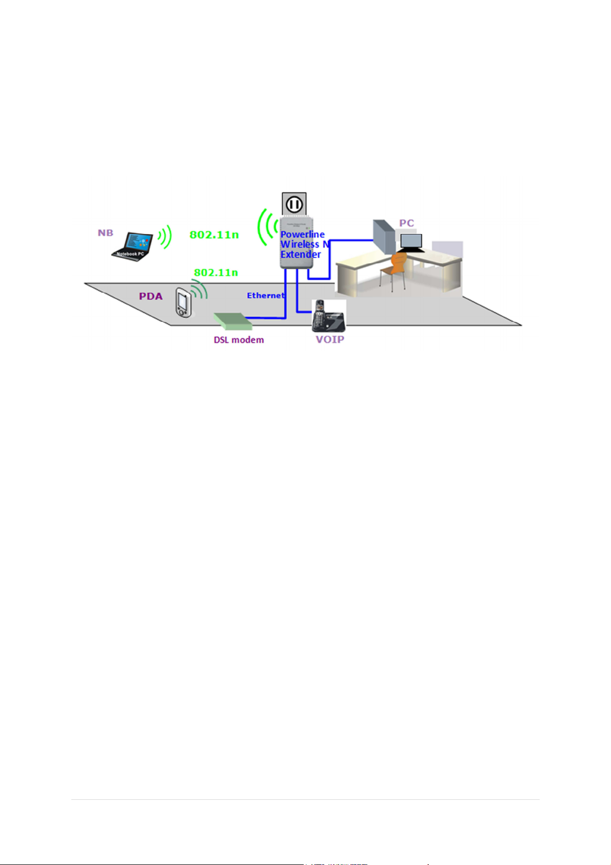
Application 2 – as wireless AP + Ethernet switch
The Wi-Fi homeplug can be a central 802.11n Access point and Ethernet switch hub to link all WLAN
devices and Ethernet devices.
10 | P a g e
Page 11
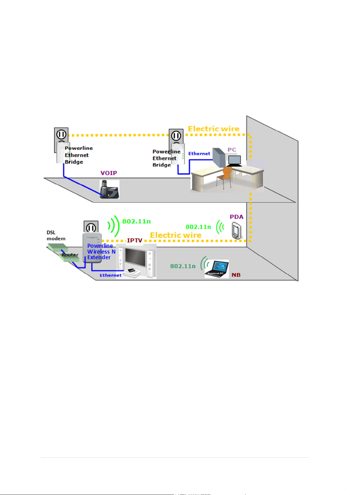
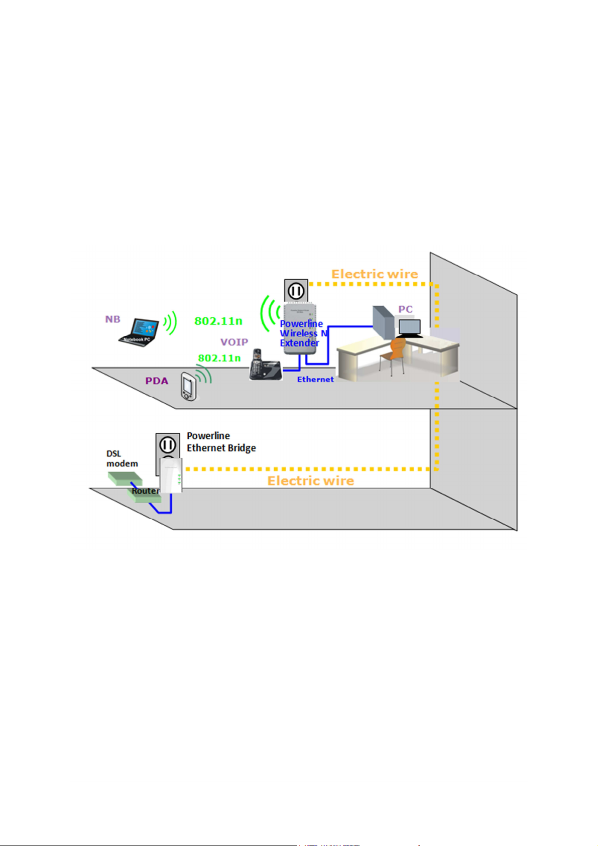
Application 3– multiple floor home networking
When WLAN signal is not good to penetrate concrete floors, use Powerline technology afforded by
the Wi-Fi homeplug to extend home networking range to upper (other) floors. While on the same
floors, the WLAN function can be used for network-enabled devices (such as PC, NB, smart phone) to
access internet. Please see the graph’s illustration. Note that this needs Powerline to Ethernet
Bridge devices for users at other floors to access network resources via the Powerline
communication.
11 | P a g e
Page 12
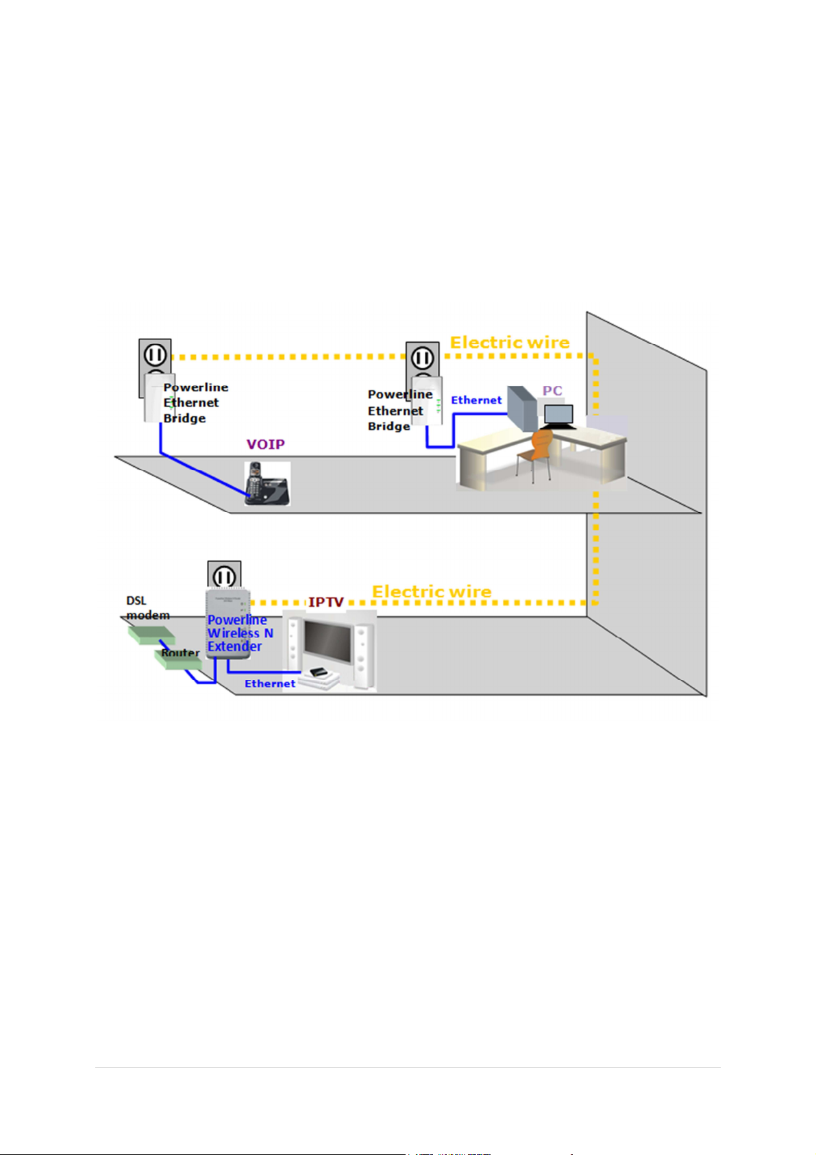
Application 4–as Powerline Ethernet switch
By pushing the Wireless Setting button for more than 1 sec, the WiFi function of this device can be
turned ON or turned OFF. In this case, Wi-Fi homeplug acts as Powerline to multiport (3 port)
Ethernet switch, which, when used together with a remote Powerline Ethernet Bridge, enables two
remote Ethernet devices (ex. PC, Notebook, or VIOP) on different floors or locations at home to
communicate via the embedded Powerline technology. In the same time, 3 RJ-45 ports on this
product can as well provide local Ethernet switch hub function.
12 | P a g e
Page 13
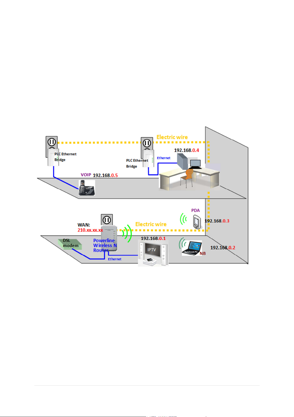
Application 5 – Wireless AP w/ Router
By pushing the WiFi Setting button > 5 sec, the Router function is enabled. When keep pushing the
Button, observe the LED to be OFF and ON for 5 times then release the button after the flashing LED
become steady ON, By default DHCP server is enabled in the Router mode. DHCP server can assign
dynamic IP address to devices connecting the LAN port of this Router. In this case, the leftmost
Ethernet socket is the WAN port. The other two Ethernet sockets are LAN ports. Please see the
following connection diagram.
13 | P a g e
Page 14

5. Hardware Configuration
This section describes ways of quick wireless encryption set up (using WPS button) and quick private
HOMEPLUG network group set up (for network partitions).
5.1 Setting Wireless encryption by WPS button
This button can be pressed for WPS PBC authentication. First, login the web configuration to setup
the wireless encryption to enable WPA2-PSK, and then enable the WPS Configuration as well. Now
press the WPS button on this device and then press WPS button on the WLAN station/client card to
start WPS process. It also works if pressing WPS button on the WLAN station card first and then this
device. The WPS process will be started and connected after a few seconds.
For those WLAN station card without physical WPS button, the software WPS button should be found
in its utility software for this function.
Any ‘Homeplug-AV’ compliant Homeplug which comes new from the box, including this device,
has a default network name of HomeplugAV. It can communicate with other brands of new
Homeplug-AV compliant devices, thus these new devices are so called belonging to the public
network. Pushing the GROUP button of the device will change its network name. This way, users
can create one or multiple private Homeplug network groups using this button, without
complicated setup software involved, thus protect their data which is being transmitted over the
power line. Pressing the RESET button of a power-active Homeplug device will reset the network
name back to its factory default (HomeplugAV).
By pushing the GROUP button for more than 10 seconds, a random network name (different
from HomeplugAV) for the device will be generated. This device can then ask other devices to
join its Homeplug network to form a private network group. Any other device, the Slave
Homeplug for instance, which wants to join this device’s (the Master) Homeplug network group
can be added by the steps below: (NOTE: it is more convenient to bring devices, which are to be
configured into the same logical network group, side by side during this procedure. After the
network group is set, the devices can be deployed anywhere at home)
14 | P a g e
Page 15

5.2 Create a private encrypted network
Step 1: Create a secure network.
First clear the public network and create a private network on HomePlug A by
pressing the GROUP button more than 10 seconds until all LED lights
simultaneously turn off and on once. Do the same on HomePlug B. At this
moment, the network names have changed to a random name and are ready to
be joined together.
Step 2: Join the secure network.
Press the GROUP button of both HomePlugs for 2 to 3 sec (make sure the
POWER LED starts blinking). It doesn’t matter which device’s button is pushed
earlier than the other, but please push the second device’s Group button within
two minutes after pushing the first device’s Group button. This way, HomePlug B
joins the same encrypted network as HomePlug A.
Please note: If you want to connect with any of the below Sitecom
Homeplugs, press the NMK button on these for 5~8 seconds to join a
secure network.
- LN-506/LN-516
- LN-507/LN-517
- LN-508/LN-518
- LN-509/LN-519
5.3 Add an extra Homeplug
First, clear the original network group of the extra HomePlug by pressing its GROUP button more
than 10 seconds until all LED lights simultaneously turn off and on once. At this moment, its
network group name has been changed to a random name and is ready to be assigned another
network name.
Next, press the GROUP button of the extra HomePlug and the GROUP button on a HomePlug that
is already connected to the network for 2 to 3 sec (make sure the POWER LED starts blinking). It
doesn’t matter which device’s button is pushed earlier than the other, but please push the second
device’s Group button within two minutes after pushing the first device’s Group button. This way,
the extra HomePlug joins the same encrypted network as the rest.
15 | P a g e
Page 16

Note:
5.4 Remove a device from a network Group
If for example, device A and device B are in the same logical network group and you want to
remove device A from this logical network group, just follow the procedure in Step 1 by pressing
GROUP button of device A for 10 seconds. This makes device A unable to communicate with
device B.
5.5 Make two public network devices private
If you want to make two new public devices (network name HomePlugAV) to become private,
please carry out Step 1 on both devices, then do step 2 on these two devices. Finally, a private
random network name is generated for these two devices.
5.6 Standby Mode
The standby mode enables the Homeplug to save power consumption. The Homeplug
automatically enters standby if no Ethernet cable is connected, or the connected device enters
standby, hibernation, or is powered-off for over two minutes. During standby, only the POWER
LED blinks at a slow rate. To exit standby, just insert the Ethernet cable to the Homeplug, or wake
up the connected device.
Some computers support the Wake on LAN function that may cause
the Homeplug not to enter the standby mode.
16 | P a g e
Page 17
7. Configuring the LN-521 via the GUI
LOGIN procedure
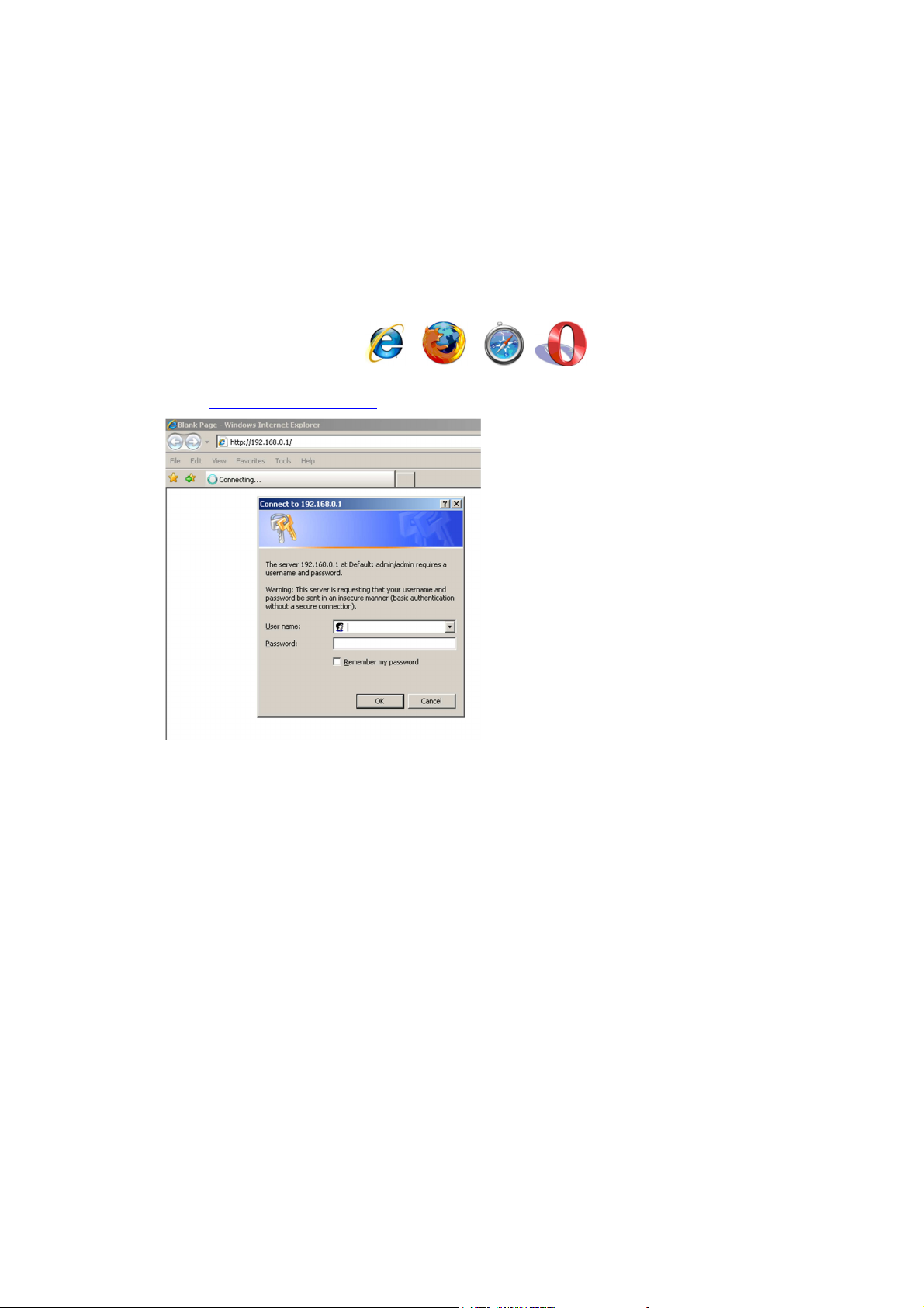
1. OPEN your browser (e.g. Internet Explorer).
2. Type http://192.168.0.234 in the address bar and press [Enter]
17 | P a g e
Page 18
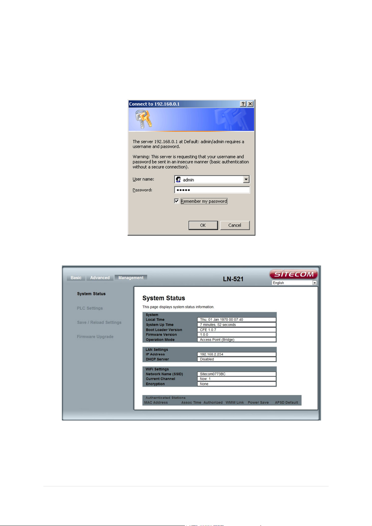
3. Type user name and password (default username is ‘admin’, the password can be
found on the backlabel of the LN-521).
4. Click OK.
5. You will see the home page of the LN-521.
The System status section allows you to monitor the current status of your LN-521
the UP time, hardware information as well as firmware version information is displayed
here.
18 | P a g e
Page 19

Basic
Setup Wizard
The setup Wizard can help you to setup the device with minimum setting. Open the page in the left
panel and click “Next” button in the welcome page.
In the next page, choose the device to be “Access Point” mode or “Router” mode. Choosing each
mode will have the respect setting pages like the figure below. Please refer to the pages in the next
section for the explanation of each setting. In the final step of setting, click “Finish” button and the
device will reboot to apply the settings.
19 | P a g e
Page 20
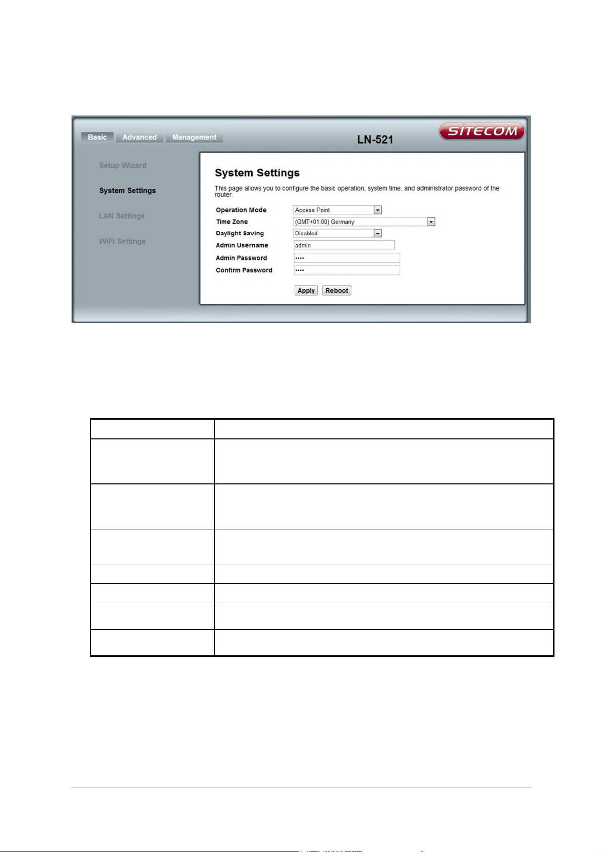
System settings
Item
Description
Operation mode
:
This device acts as Wireless Access Point (
AP
) to provide WLAN service
Operation mode
:
This device acts as Wireless Access Point to provide WLAN service and
Time Zone
Select your time zone for this device. The system time will be updated
Daylight Saving
Default is ‘disable’. Select to enable day light saving time.
Admin Username
Default name is “root”. Enter new name to change it.
Admin Password
Default password is “root”. Enter new password to change it.
Confirm Password
If password
is entered in the above field, enter it again here to confirm.
This device supports two operation modes for the IP network. Click to select one between the
following two wireless operation modes, then push the “Apply” button.
Access Point
Router
and bridge it to wired connection.
router to connect LAN/WLAN to the Internet.
from the Internet.
20 | P a g e
Page 21
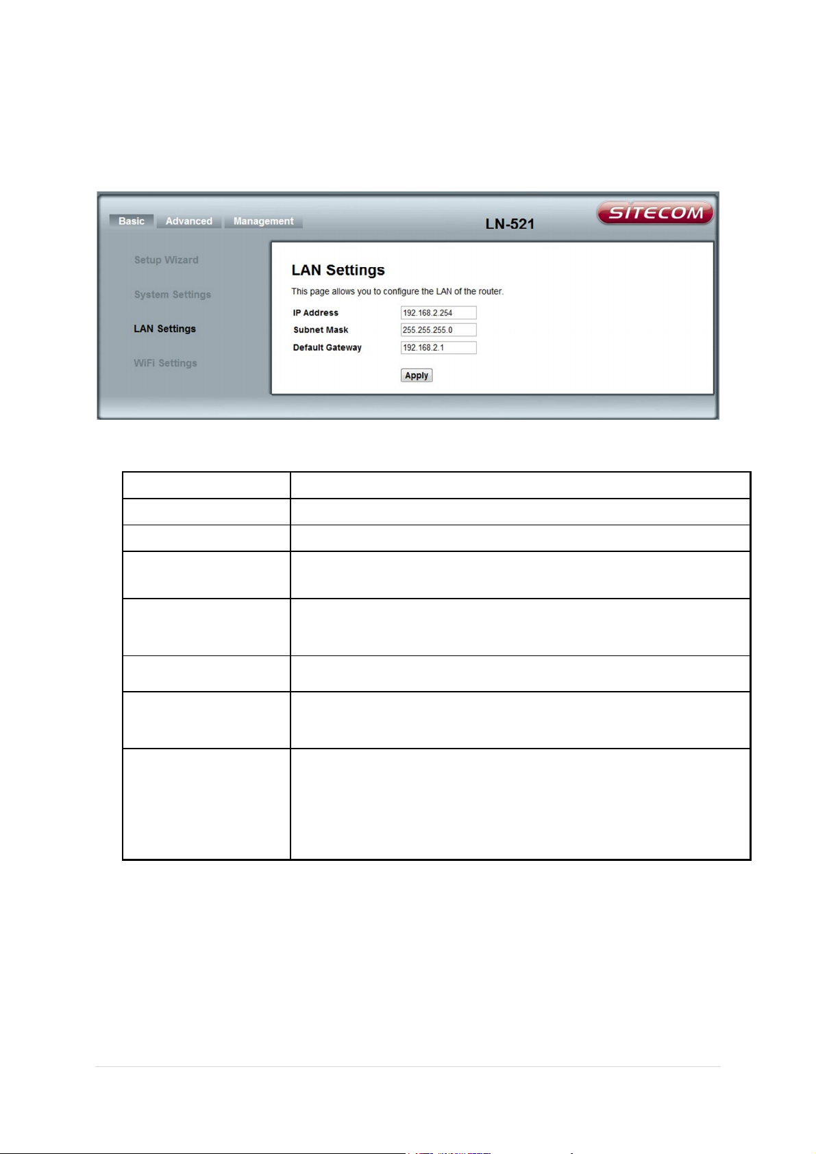
Lan Settings
Item
Description
IP Address
Setup the IP Address for the LAN interface.
Subnet Mask
Setup the subnet mask for the LAN
interface.
Default Gateway
This option only appears in “
Access Point
” mode. Setup the default
DHCP Server
The DHCP Server is only available in “
Router
” mode. Choose to enable
DHCP Starting IP
Enter the starting IP Address to assign to DHCP clients.
DHCP Ending IP
Enter the ending IP Address to assign to DHCP clients. The LAN IP
DHCP Lease Time
Enter the time. The DHCP
renew, release time will be calculated
Setup the LAN settings for LAN interface.
gateway for the LAN interface.
or disable DHCP server for the LAN interface.
Address of this device must not be included in this range.
according to it. If you got a lot of PCs, networking devices, DHCP clients
come and go frequently, the shorter time should be considered to avoid
DHCP IP addresses consuming, and otherwise you can keep the default
value.
21 | P a g e
Page 22

WiFi Settings
Item
Description
Network Name (SSID)
Setup this name and then WLAN clients can scan and connect to this
Control Channel
Select the WLAN channel for this device.
WPA
-
PSK Enable or disable this kind of wireless encryption.
WPA2
-
PSK Enable or disable this kind of wireless encryption.
Setup the Wi-Fi settings for WLAN interface. Click “Apply” button to apply the settings.
device by this name in the air. The Network Name (SSID) is also called
ESSID.
Select “Auto” and the device will scan and select the available radio
channel.
When the channel is selected, the interference level will be showed next
to this option.
NOTE: when OBSS is on and Bandwidth is set to 40MHz, auto channel
selection will be enabled if under noisy environment.
If you enable WPA-PSK only, the WPS function will be disabled.
To support WPS function, the WPA2-PSK must be enabled.
22 | P a g e
Page 23

WPA Encryption
Choose “AES” or “TKIP+AES” as the encryption method.
WPA Passphrase
Enter 8 to 63 characters passphrase for WPA Encryption.
MAC Restrict Mode
The default value is “Disabled”.
Select “AES” and the WLAN client must select “AES” to connect to this
device. Select “TKIP+AES” and the WLAN client can use AES or TKIP to
connect to the device.
The WLAN clients must setup the same WPA Passphrase to connect to
this device.
Choose “Allow” to allow WLAN clients in the list only.
Choose “Deny” to reject WLAN clients in the list.
After choosing “Allow” or “Deny”, the list will appear, and you enter the
MAC Address of WLAN clients to apply the “Allow” or “Deny” rule.
23 | P a g e
Page 24

Advanced
Item
Description
Network Name Type
Select “
Visible
” to broadcast Network Name (SSID, Service Set
Bandwidth
Choose “20 MHz” or “40 MHz” bandwidth. The wider bandwidth
OBSS Coexistence
OBSS
(Overlapping BSS) Coexistence is only available when using 40 MHz
NPHY Rate
Choose the MCS (Modulation Codec Scheme) mode for radio to decide
Fragment Threshold
The fragmentation threshold determines the size at which packets are
WiFi Advanced
Identification) or “Hidden” to not to broadcast it. With hidden Network
Name (SSID), this device can’t be scanned and the wireless client must
input Network Name (SSID) manually to associate this AP.
provides higher physical data rate.
bandwidth. The default is on and the device will scan the channel to find
if any overlapping signals, if so, it uses 20 MHz only. Turn off this option
and the device will force to use 40 MHz.
NOTE: when OBSS is on and Bandwidth is set to 40MHz, auto channel
selection will be enabled if under noisy environment.
the Physical Data Rate. MCS 0-7 is the 1T1R radio and MCS 8-15 is the
2T2R radio. The “Auto” option is recommended to let the device to
adjust it automatically.
fragmented (sent as several pieces instead of as one block). Use a low
setting in areas where communication is poor or where there is a great
deal of radio interference. You can enter a setting ranging from 256 to
2346 bytes.
24 | P a g e
Page 25

RTS Threshold
The RTS threshold determines the packet size at which the radio issues a
Beacon Interval
Beacons are the packets sending by Access point to synchronize the
BSSID
The BSSID is the MAC Address of the WLAN interface and displayed
request to send (RTS) before sending the packet. A low RTS Threshold
setting can be useful in areas where many client devices are associating
with the device, or in areas where the clients are far apart and can
detect only the device and not each other. You can enter a setting
ranging from 1 to 2347 bytes.
wireless network. The beacon interval is the time interval between
beacons sending by this device. The default and recommended beacon
interval is 100 milliseconds.
here.
25 | P a g e
Page 26

WPS Settings
Item
Description
WPS Configuration
Select “Enable” to en
able or “Disable” to disable this function.
Device Name
Enter the Device Name for WPS process.
This function helps to establish the Wi-Fi security. For this AP device, it can be setup one WPS
method including PIN (Personal Identification Number) and PBC (Push Button Certification).
To begin the WPS progress, the WLAN security must be setup first. Please setup one at least WPA2PSK for Wi-Fi security.
PIN: enter the PIN code in the utility of the WLAN client connecting to this AP, and then enter it in
the “Station PIN” field. The Wi-Fi link between the WLAN client and the device would be encrypted.
You can also find the Device PIN in the “WPS settings” page and enter it in the AP PIN field in the
WLAN client utility to establish WLAN encrypted connection.
PBC: select PBC, and then you can begin the PBC process. Press the PBC button in the panel can also
trigger this process. Press or click the PBC button on the WLAN client to finish the communication.
You can press the PBC button on the WLAN client first and then click the PBC button on this device to
establish the encryption.
26 | P a g e
Page 27

WPS Config State
Select “Configured” and the WLAN client which is setup “
Enrollee
” type
of WPS will be transferred and apply the same Wi-Fi setting on this AP
WPS Method
Select
PBC (Push Button Configuration) or PIN (Personal Identification
Station PIN
For PIN method, find the PIN code in the utility of the WLAN client
WPS Status
Show the status of the WPS process.
Device PIN
It shows the current PIN number of this device.
device.
Select “Not Configured” and the WLAN client which is setup “Registrar”
type of WPS will transfer Wi-Fi setting to this AP device in the WPS-PIN
process, and then this device will apply the new setting from this WLAN
client.
Number) as the method.
connecting to this AP, and then enter it in the PIN field. The Wi-Fi link
between the WLAN client and the device should be encrypted.
If the above settings are configured, press “Start” button to begin.
To change the current PIN number of the device, press “Generate” to
change it.
27 | P a g e
Page 28

Management
Item
Description
Local Time
It shows the time on this device. If the device connects to the
System Up Time
It
shows the duration of the system up.
Boot Loader Version
It shows the version of Boot Loader.
Firmware version
It shows the current firmware version of the device.
Operation Mode
It shows the operation mode of the device.
System Status
System Info
Internet, the time will sync with the NTP server.
28 | P a g e
Page 29
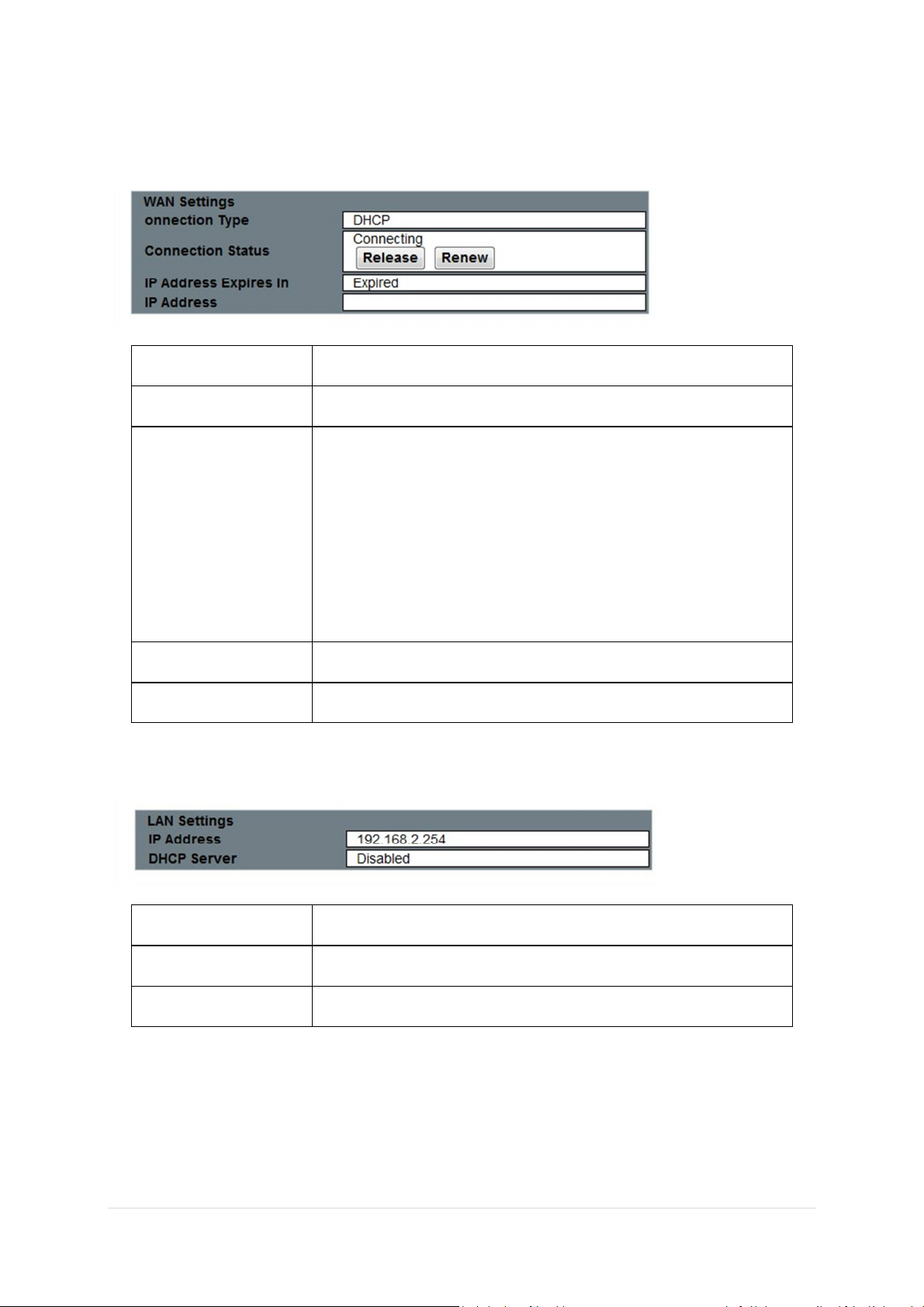
WAN Settings
Item
Description
Connection Type
It display the type of the WAN interface
Connection Status
It shows the connection status of WAN interface.
IP Address Expires IN
It shows the DHCP lease time from DHCP server.
IP Address
It shows the current IP Address for WAN interface.
Item
Description
IP Address
This is the IP Address of the LAN interface.
DHCP Server
It shows the DHCP
server status on LAN interface of the device.
The WAN Settings only appear in Router mode.
For WAN-PPPoE-Manual setting, there are two buttons “Connect”
and “Disconnect” here for PPPoE connection.
For WAN-DHCP setting, there are two buttons “Release” and
“Renew” for DHCP operation. Click “Release” to release IP Address
assigned from ISP or DHCP server. Click “Renew” to renew DHCP IP
from ISP or DHCP server.
LAN Settings
29 | P a g e
Page 30

WiFi Settings
Item
Description
Network Name (SSID)
It shows the SSID of this device.
Current Channel
It shows the current channel of the radio.
Encryption
It indicates the encryption type for the radio.
Active DHCP Leases
The WLAN/LAN hosts assigned IP by this device will be listed in the table.
Active DHCP Leases
The associated WLAN clients will be listed in this table.
PLC Settings
This page shows all the current settings of the Homeplug network. The device can be restarted by
pressing the Restart button.
30 | P a g e
Page 31
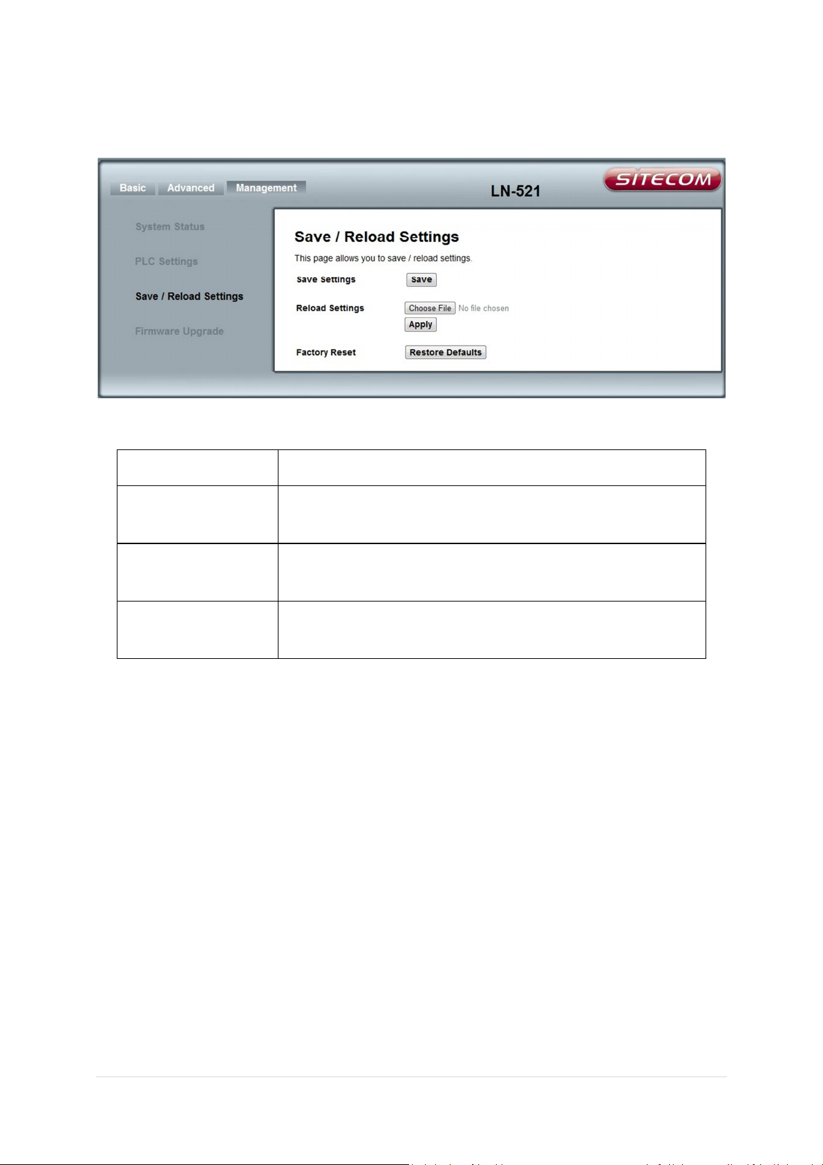
Save / Reload Settings
Item
Description
Save Settings
Click the “Save” button to save the device configuration to your
Reload Settings
Click the “Browse…” button to browse and find the old device
Factory Reset
Click the “Restore Defaults” button to reset the device to factory
PC.
configuration file on your PC. Click “Apply” button to apply the file.
default.
31 | P a g e
Page 32
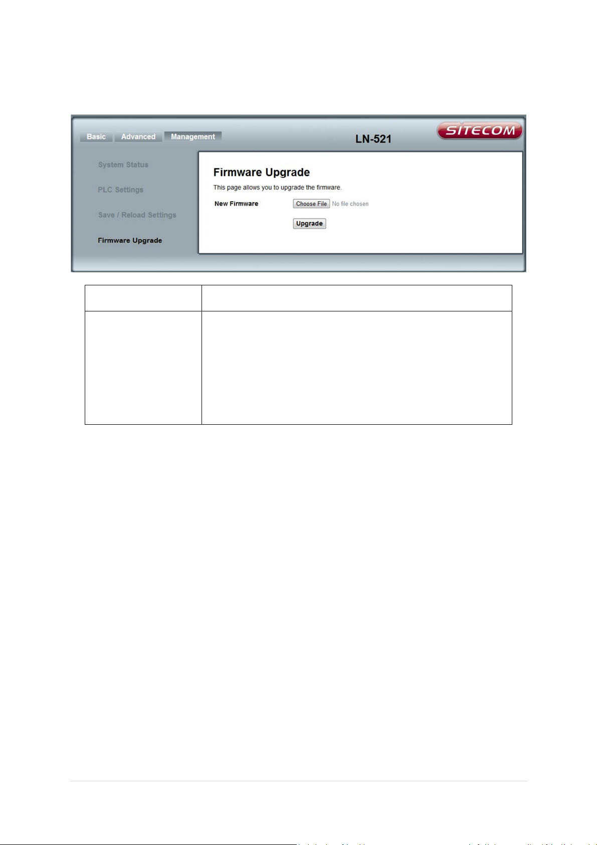
Firmware Upgrade
Item
Description
New Firmware
Click “Browse…” button to browse and find the firmware on your
PC, and then click “Upgrade” button to upgrade.
The upgrade process takes about 1 minute and DO NOT POWER
OFF the device during this period. In order to continue
configuration, please refresh the PC web-browser to reflect new
upgraded FW settings.
32 | P a g e
Page 33
Using the Utility
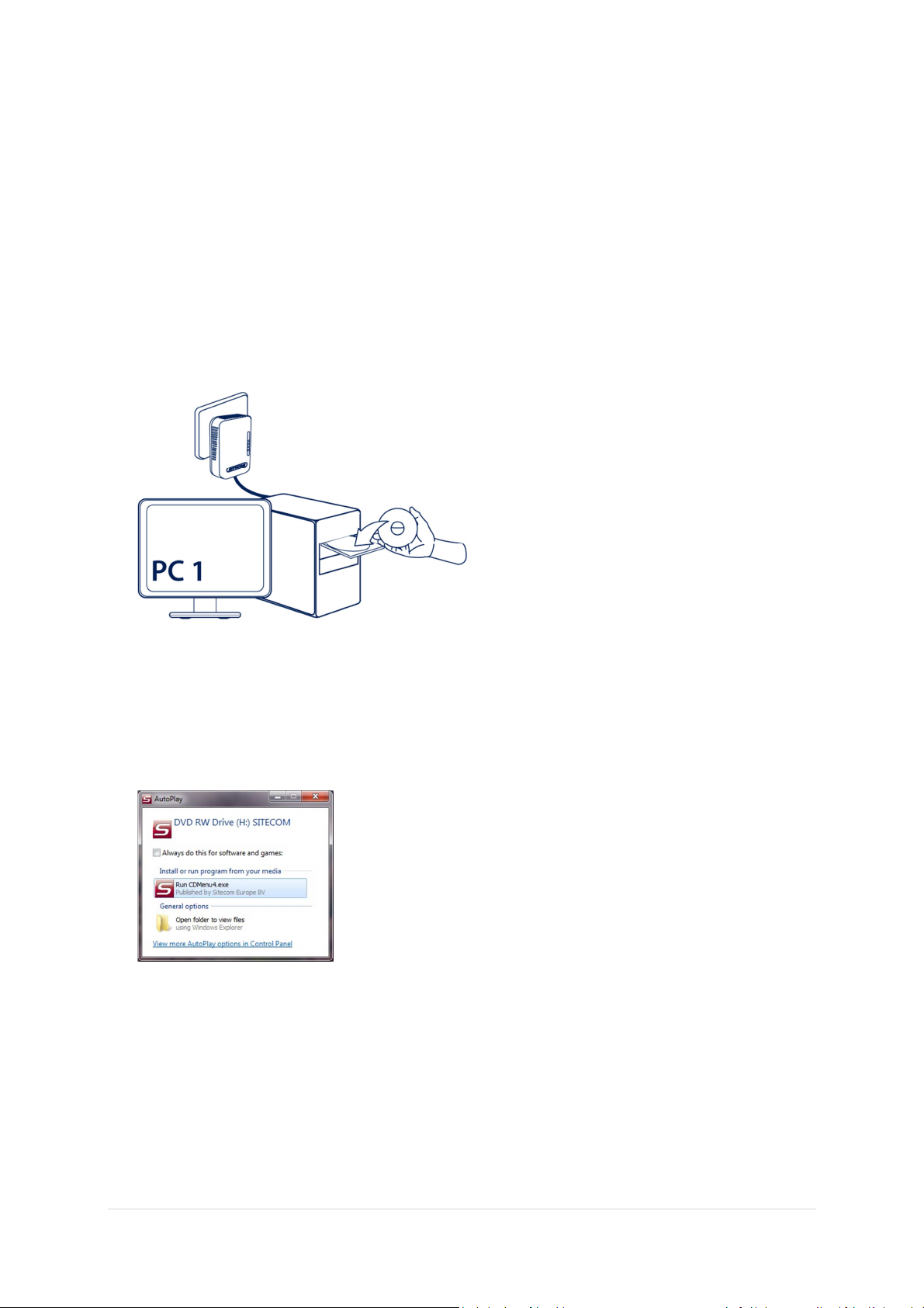
Installation
Install the software only on the PC which is connected to the Homeplug. Insert the CD in the
computer.
Windows 7/Vista will prompt you to run CDMenu4.exe.
The CD menu will start. Choose ‘Install utility’.
33 | P a g e
Page 34
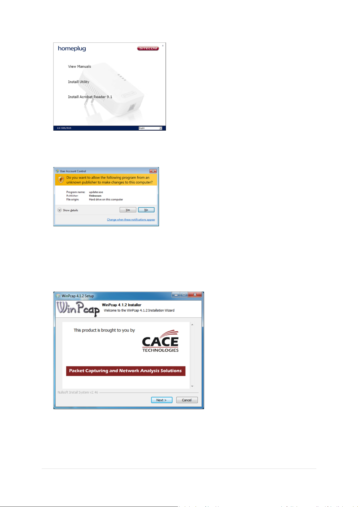
Windows Vista/7 will ask permission to start the installation which looks similar to this image.
The WinPcap Installer will start, click Next.
Click Next
34 | P a g e
Page 35
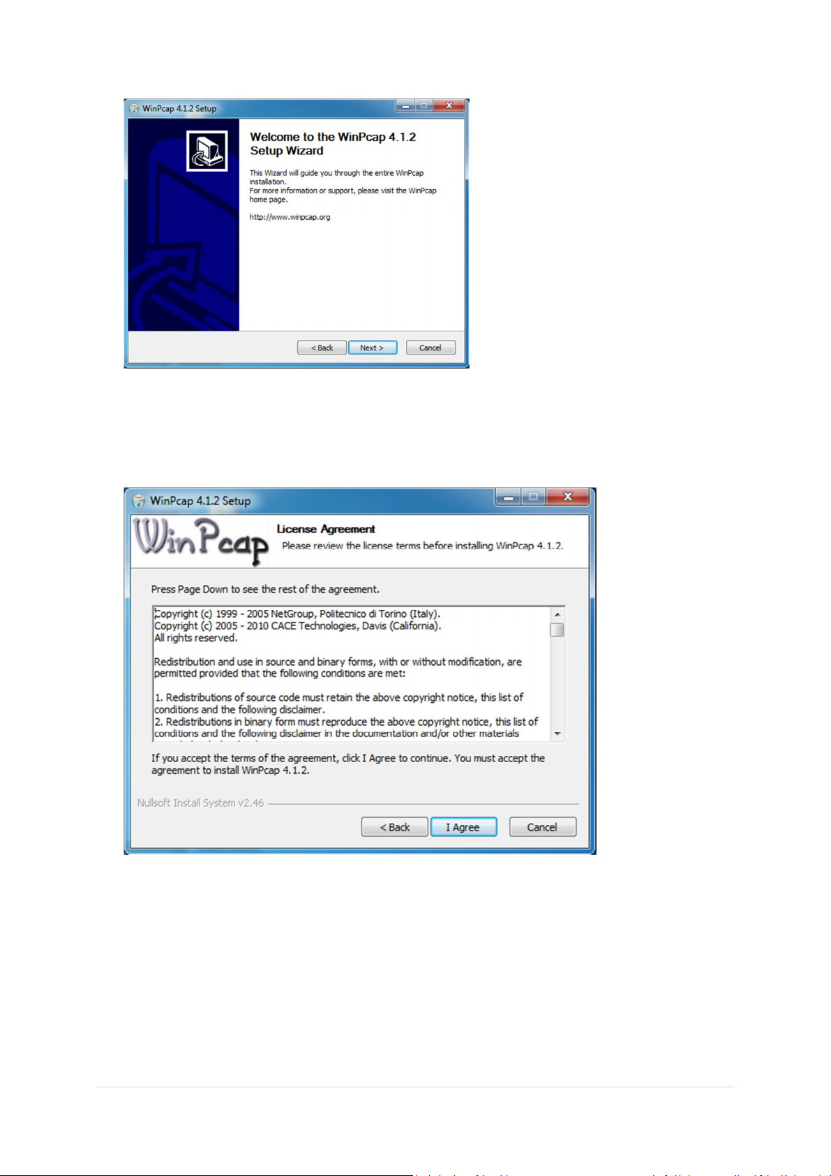
Click Next
Click I Agree.
35 | P a g e
Page 36

Click Install.
Click Finish
Once WinCap has installation has been finished the Homeplug utility will be installed.
36 | P a g e
Page 37

Click Next
Enter a User name and click Next
37 | P a g e
Page 38

Select Complete to let the software automatically Install.
Choose Custom if you wish to select a different location for the Installation.
Click Next continue
Click Install
38 | P a g e
Page 39
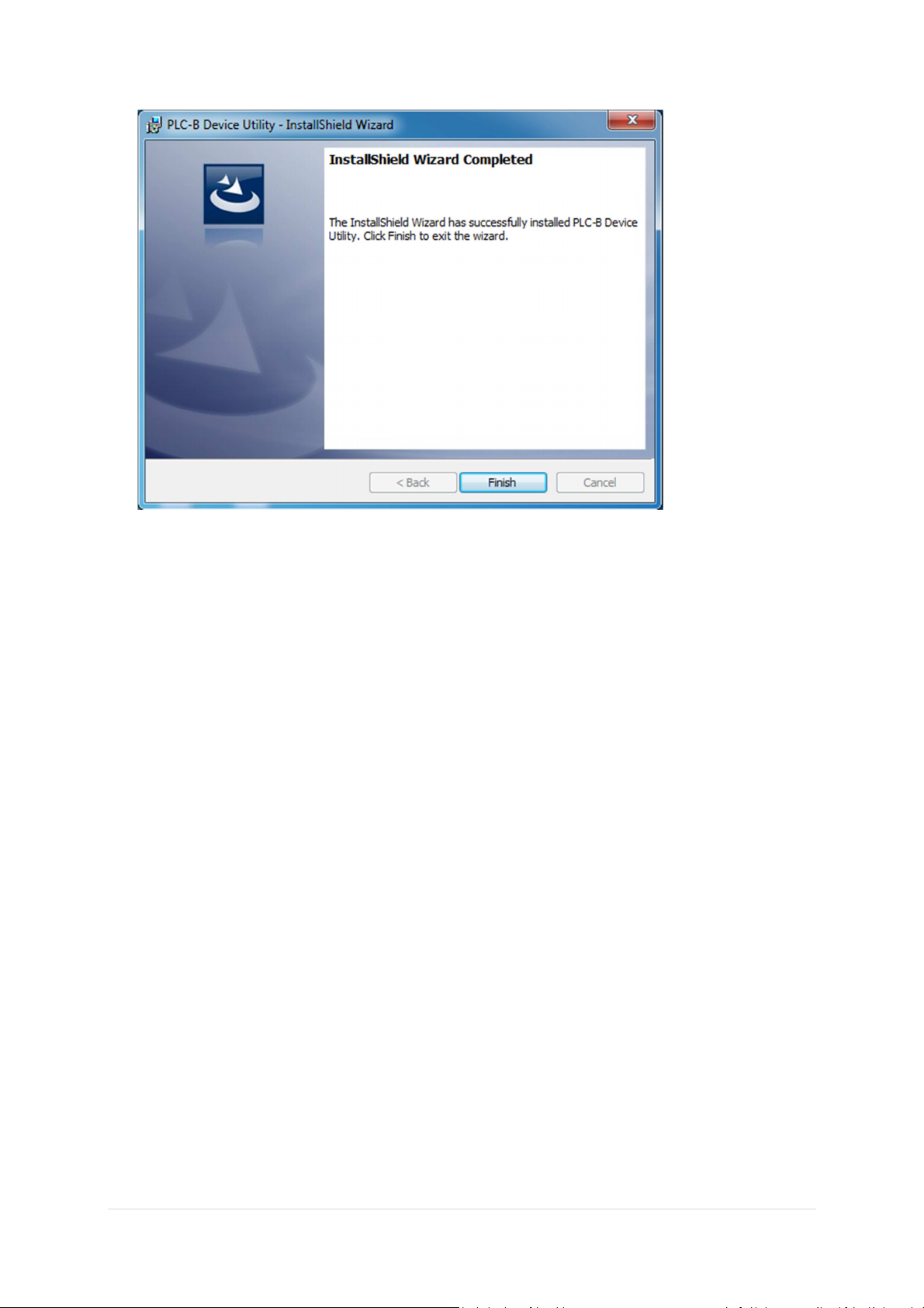
The software will confirm that the installation has completed, click Finish.
39 | P a g e
Page 40
Configuring using the Utility
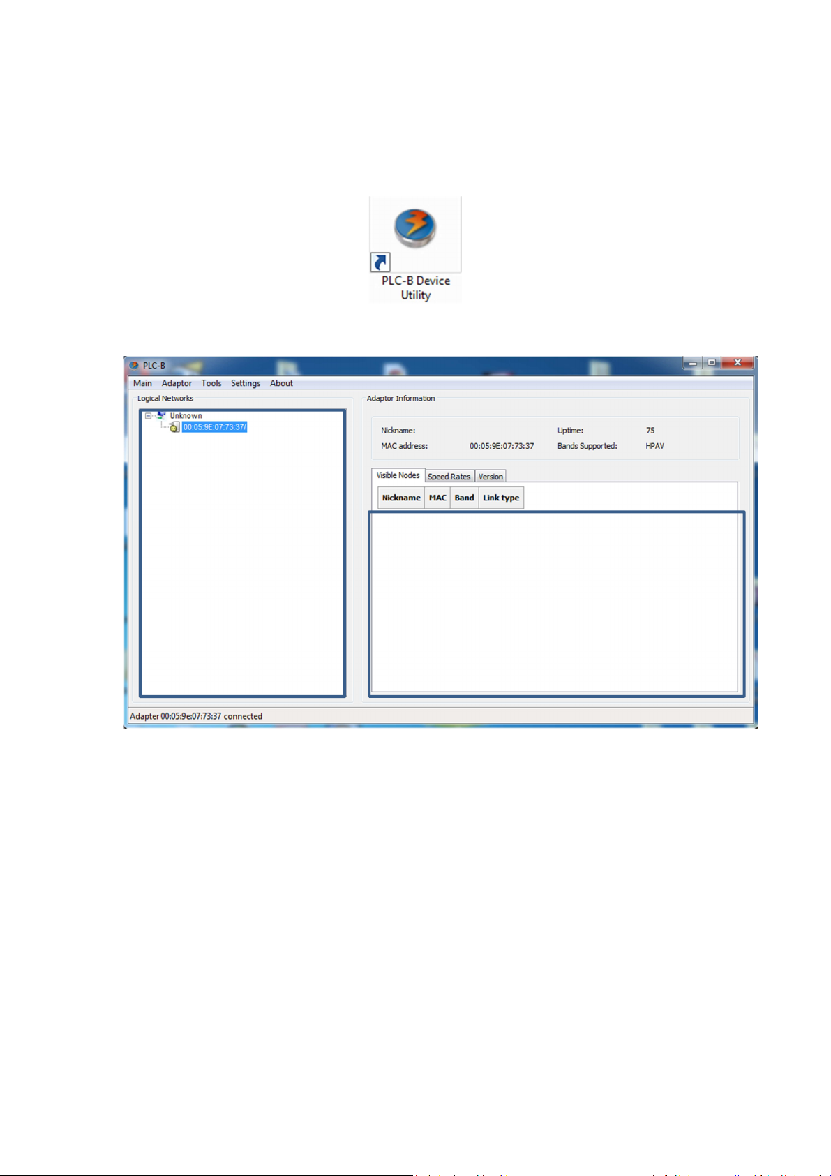
Click the shortcut on the desktop to start the Utility
When the utility has been started the following screen will be shown.
The panel on the left side shows the Homeplug that is directly connected to the pc.
The panel on the right shows remote connected Homeplugs.
40 | P a g e
Page 41
To change the network name of the local connected homeplug.
For optimal compatibility with other Homeplugs we
strongly
adv
ice only to use capital letters for the
Right click on the device in the left panel . This will show new options as indicated in the screenshot
below.
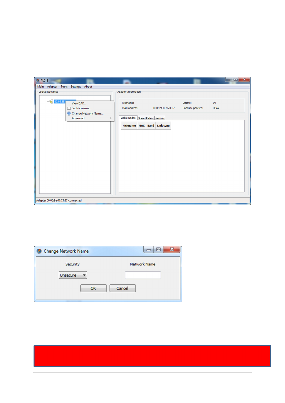
To change the network name select ‘Change Network Name’
The following pop-up will be shown.
Enter the desired network name and click ‘OK’
The network name of the local homeplug will now be changed.
network name.
41 | P a g e
Page 42

Declaration of Conformity
42 | P a g e
Page 43
43 | P a g e
Page 44

Revision 1.0
© Sitecom Europe BV 2012
Note: All the information contained in this manual was correct at the time of publication.
However, as our engineers are always updating and improving the product, your device may have a
slightly different appearance or modified functionality than presented in this manual.
44 | P a g e
 Loading...