

Page 1
Page 2

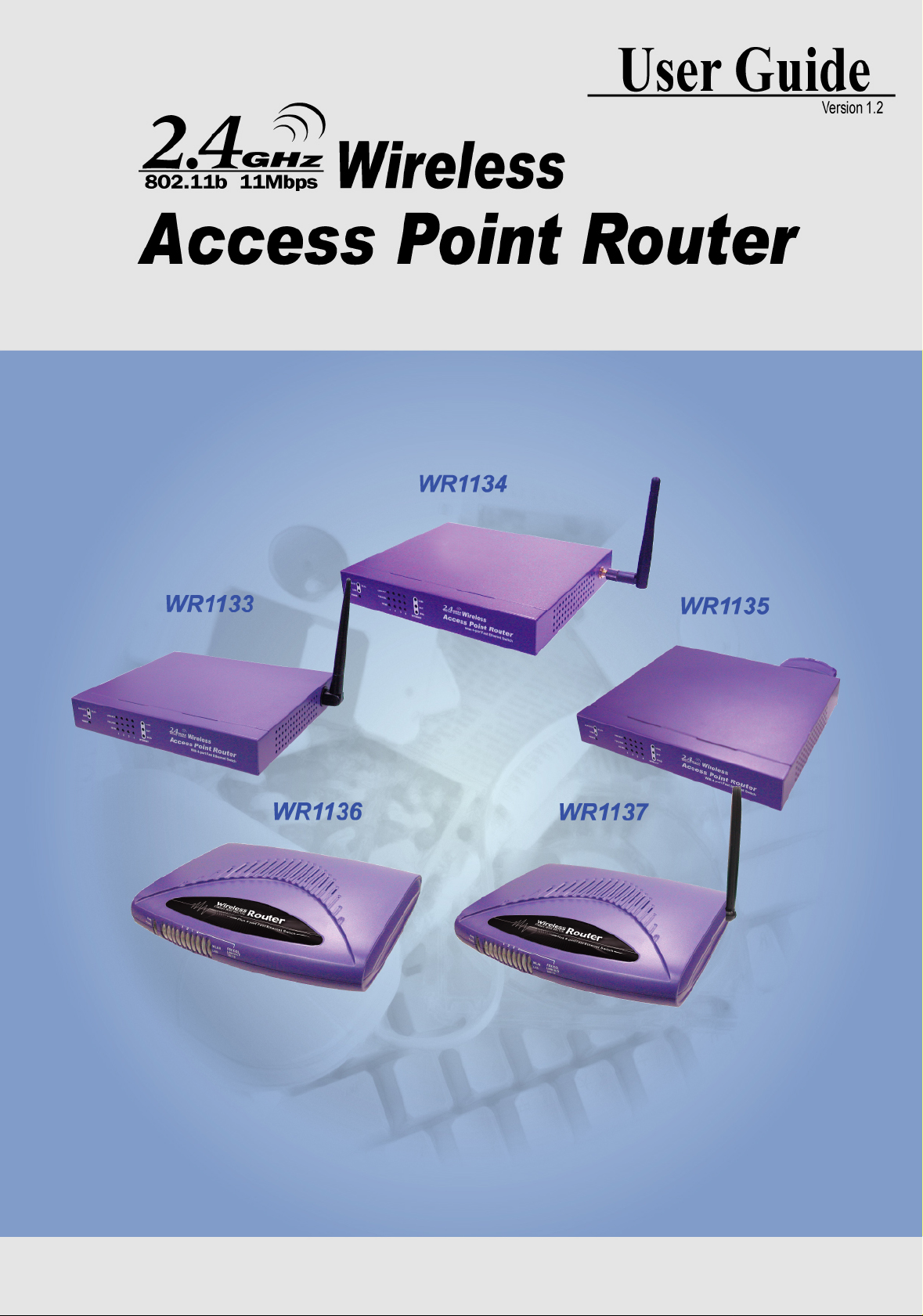
Wireless Acccess Point Router
The information in this guide may change without notice. The manufacturer assumes
no responsibility for any errors which may appear in this guide.
Fast Ethernet is a tr ademark o f XER OX Cor poration. Mi crosof t, Windows and Windows
logo are trademarks of Microsoft Corporation.
Copyright 2002. All right reserved. No Part of the contents of this guide maybe
transmitted or reproduced in any form or by any means without the written permission
of the manufacturer. Printed in Taiwan.
The revision date for this guide is NOV 22nd, 2002
Version 1.2
FCC Certifications
The This product has been tested and found to comply with the limits for a Class B
digital device pursuant to Part 15 of FCC Rules. These limits are designed to provide
reasonable protection against such interference when operating in a commercial
environment. This equipment gener ates, uses and can r adiate radio frequency energy,
and if not installed and used according to the instructions, may cause harmful
interference to radio communications.
Operation of this equipment in a residential area is likely to cause interference in which
case the user, at his or her own expense will be required to take whatever measures
may be required to correct the interference.
CE Mark Warning
This is a Class B product. In a domestic environment, this product may cause radio
interference in which case the user may be required to take adequate measures.
1
Page 3

1: Introduction
1.1 Before You Start
1.2 System Requirement
1.3 How to Use this Guide
2: Hardware Installation
2.1 Product Description
2.1.1 Overview
2.1.2 Features
2.1.3 Front Panel
2.1.4 LEDs and Reset Button
2.1.5 Rear Panel
2.2 Installing the Router
2.2.1 Preparing for the installation
Wireless Acccess Point Router
Contents
2.2.2 Getting Started
3: Configuration
3.1 Configuring the Wireless Access Point Router
3.2 The Setup Wizard
3.2.1 PPPoE Connection for WAN
3.2.2 Fixed IP for WAN
3.2.3 PPTP For WAN
3.2.4 Dynamic IP for WAN
3.2.5 Alias IP Setup
3.2.6 DNS
3.2.7 Wireless Configuration
3.2.8 Time Zone
3.3 Browsing the Status
3.3.1 Status
3.3.2 Wireless Status
3.3.3 DHCP Table
3.3.4 Routing Table
3.3.5 DDNS Status screen
3.4 Viewing the Tools
3.4.1 System Log
3.4.2 Hacker Log
3.4.3 Reset
3.4.4 Upgrade
2
Page 4

Wireless Acccess Point Router
3.4.5 Backup
3.5 Setup the Advanced Features
3.5.1 LAN IP Setting
3.5.2 DHCP Setting
3.5.3 Firewall Setting
3.5.4 Privilege
3.5.5 Virtual Servers
3.5.6 Routing
3.5.7 WAN MAC Address Clone
3.5.8 DDNS Setting
3.5.9 MAC Control
3.6 Configuring your PCs to Connect to the Router
4: Specifications
4.1 Technical Specifications
4.2 Environmental Information
4.3 Standard Conformance
4.4 Cable Specifications
Appendix
A: About Static and Dynamic IP Address
B: Comparison Table of Wireless Access Point Routers
C: Warranty Statement
3
Page 5

Wireless Acccess Point Router
1: Introduction
The Wireless Access Point Router combines the technolog y of Fast Ethernet and IEEE
802.11b Wireless LAN, prov i di ng the home or smal l of fice user s the C abl e/DSL access
to the Internet via cord and cordless connection. At the same time, integrated with the
firewall and 128-bit WEP (Wired Equivalent Privacy) Encryption, the Wireless Access
Point Router allows multiple users to share one Internet connection while ensuring the
safety and security of the packet flow.
Throughout this guide, the Wireless Access Point Router may be referred to as the
Router.
1.1 Before You Start
Check the package of the router before you start. The package contents come with:
One Wireless Access Point Router
One AC/DC Power Adapter
CD
- User Guide
1.2 System Requirement
Before you getting started, make sure you meet the following requirements.
One RJ-45 Cable/DSL network connection
One PC with installed 10/100 Mbps Ethernet Adapter
UTP network cable with RJ-45 connector
Windows 95/98/2000 or Windows NT for the Web-based Configuration
Either Microsoft I nter net Ex plorer 4.0 ( or abo ve v ersi on) or N etscap e Nav ig ator 4.0
(or above version)
For Wireless Connection
One PC with installed Wireless Network Adapter
4
Page 6

Wireless Acccess Point Router
1.3 How to Use this Guide
This guide is structured as follows:
Chapter 2, Hardware Installation explains the function of the router and how to
physically install it.
Chapter 3, Configuration explains how to set up and modify the configuration of
the router with its Web-based utility. In addition, the configuration of the PCs that
you want to connect to the Router can be found within this chapter.
Chapter 4, Specifications contains information about the cables, environment and
the technical specifications of the router.
Appendices include the information of Static IP address and Dynamic IP address,
comparison table and warranty Statement. Read them as necessary.
5
Page 7

Wireless Acccess Point Router
2: Hardware Installation
2.1 Product Description
This chapter describes the features and functions of the router and shows how to
physically install it.
2.1.1 Overview
As the interface between WAN and LAN, the Wireless Access Point Router combines
the technology of Fast Ethernet and IEEE 802.11b Wireless LAN, providing the home
and small office users the broadband access to the internet via cord and cordless
connection. Meanwhile with the integration-the firewall and 128-bit WEP (Wired
Encrypted Privacy) Encryption, the Wireless Access Point Router allows multiple users
to share one Internet connection while ensuring the safety and security of the packet
flow. Also, the design of one antenna will enhance the reception of signals transmitting
from wireless adapters.
Strictly compliant with IEEE 802.11b, the Wireless Access Point Router features the
transmission rate up to 11 Mbps and 2.4 GHz frequency band, easily building up the
wireless communication with other Wireless LAN devices. The local users' IP address
masking and specific port blocking offer two levels of security. Also, the Wireless
Access Point Router serves as a DHCP server that aut omatically assigns IP address to
the devices on your local area network (LAN).
2.1.2 Features
Interoperable with IEEE 802.11b (DSSS) 2.4GHz compliant equipment
Transmission speeds adjustable at 1, 2, 5.5, and 11 Mbps.
Features 2.4 GHz frequency band.
Capable of up to128-bit WEP (Wired Equivalent Privacy) Encryption secures the
network connection.
MAC address filtering
Supports PPPoE, PPTP Client, and Dynamic DNS
Connects to a Cable/DSL modem or to an Ethernet backbone
Equipped with a 4-port 10/100 Mbps Switch
Creates a firewall to protect your PCs from outside intruders
Configurable through any networked PC’s web browser
Speeds up the gaming and multimedia connections dramatically
Simultaneously act as either a DHCP server on the LAN or a DHCP client on the
6
Page 8
Wireless Acccess Point Router
WAN
Enables outside users to access the internal IP servers via Internet. Compatible
with virtually all standard Internet applications
Compatible with all standard internet application
Enables administrators to block specific interior users’ Internet access
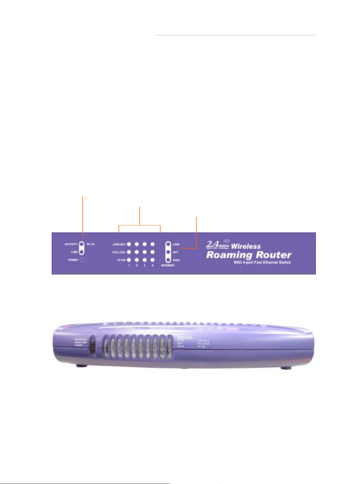
2.1.3 Front Panel
The front panel o f the r outer has 3 LEDs for e ach 10/1 00 M bps p orts , an d thr ee M odule
Status LEDs at the left. The Internet LEDs are at the right. Figure 2-1, Figure2-2, and
show front panels of these routers.
Figure 2-1 Front panel of Wireless Access Point Routers with One Optional PCMCIA
Card, One Fixed Antenna, and One Reverse SMA Antenna
WAN Status LED
10/100 Port Status LEDs
Internet Status LEDs
Figure 2-2 Front panel of Wireless Access Point Router
with Built-in PCMCIA and One Antenna
7
Page 9

Wireless Acccess Point Router
2.1.4 LEDs and Reset Button
The LEDs are explained in the following tables.
Table 2-1 WAN Status LED Functionality
LED Color Function
WLAN Act
WLAN Link
Link/Act
FULL/COL
Green
Green
Power
LED Color Function
Green
Table 2-2 10/100 Port Status LED Functionality
Green
Green
Lights to indicate the router is activated.
Lights to indicate that the Router’s wireless functions
have been enabled through the Web-based utility.
Lights to indicate the router has power.
Lights to indicate a functional netw ork l ink throug h the
corresponding port with an attached device.
Blinks to indicate that the router is actively sending or
receiving data over that port.
Lights to indicate that the connection made through
the corresponding port is running in Full Duplex mode.
Blinks periodically to indicate that the connection is
experiencing collisions.
Lights for any port to indi cate t hat the port is operati ng
100
LED Color Function
Link
Act
Diag
Orange
Green
Green
Red
at 100 Mbps.
Off to indicate that the port is operating at 10 Mbps
while the network is still operating.
Table 2-3 Internet LED Functionality
Lights to indicate a successful connection between
the Router and your broadband device or network.
Blinks to indicate that the Router is sending or
receiving data over the broadband (Internet) port.
Lights to indicate the Router’s self-diagnosis mode is
running during boot-up and restart. It will turn off when
completing the diagnosis.
8
Page 10

Wireless Acccess Point Router
2.1.5 Rear Panel
The rear panel of the router has one Reset button at the left. At the right area are the
Internet and LAN ports and a power connector. Figure 2-3, Figure 2-4, and Figure 2-5
shows rear panels of these routers. Table 2-4 explains the function of the port.
Figure 2-3 Rear panel of the Wireless Access Point Router
with One Optional PCMCIA Card
Reset Button Internet & LAN Ports DC Input Port
PCMCIA Slot Uplink/Normal Switch
Figure 2-4 Rear panel of the Wireless Access Point Router with
Fixed Antenna and one Reverse SMA Antenna
Figure 2-5 Front panel of Wireless Access Point Router
with Built-in PCMCIA and One Antenna
Table 2-4 All Port Functionality
Port Function
Reset
LAN port
Internet port
PCMCIA slot
DC Input Port
Pressing the Reset button for more than 3 seconds to
restore to the factory default setting.
This is where you connect to the PC.
This is where you connect to the Cable/DSL modem.
This is where you connect to the PCMCIA adapter.
To connect the adapter to receive power.
9
Page 11

Wireless Acccess Point Router
Caution: Reset Button
Pressing the Reset button for more than 3 seconds while the router powers up will
restore to factory de faul t setting. Note that this should be done only when you had tried
all the troubleshooting options. Pressing the Reset button during operation may bring
you into the risk of creating IP a ddress con flict betw een y our PC an d the rout er. In such
a case, you may be compelled to reboot your entire system(s).
Caution: Uplink/Normal Switch
If you press down this switch, Port 1 will become the Uplink port. If you press it a gain,
Port 1 will become a normal LAN port.
10
Page 12

Wireless Acccess Point Router
2.2 Installing the Router
This section will discuss what you should do before connecting your router to the
network and how to physically install it.
2.2.1 Preparing for Installation
Before you start to connect your router to any network device, make sure you get the
following values from your ISP. You will need those values to setup the Router and
configure you networked PCs to accept the IP address the Router chooses to assign
them.
PPPoE User Name and Password
or
Fixed Internet IP Address assigned by your local ISP
Your Subnet Mask
Your Default Gateway
Your Primary DNS IP address
or
Other values may be needed for Cable Modem users, please confirm with your
ISP
You are supposed to have all those information mentioned above from your ISP. If not,
contact your ISP and they will be able to supply all the information you need.
11
Page 13

Wireless Acccess Point Router
2.2.2 Getting Started
You may complete the following steps to install your Wireless Access Point Router
when you have all the information mentioned above on hand.
Step 1. Power all devices down. This should include your PCs, Cable or DSL modem
and the Router.
Step 2. Connect the Router to your PCs.
A. Connect one end of a standard network cable to the 10/100 RJ-45 LAN ports
on the back of the W ireless Access Point Router.
B. Connect the other end of the cable to the PC.
Step 3. Connect the Router to your Cable or DSL modem.
A. Connect one end of a standard network cable to the RJ-45 WAN port on the
back of the Wireless Access Point Router.
B. Connect the other end of the cable to either a Cable or DSL modem
Step 4. Supply the power to the Router.
A. Connect one end of the power cable to the Wireless Access Point Router.
B. Connect the power cube end of the power cable to a standard wall outlet.
When the Router receives power, the Power LED should remain solid Green.
Step 5. Supply the power to either your Cable or DSL modem.
Step 6. Press the Reset button to restore the Wireless Access Point Router‘s default
settings. Hold the button in for three seconds, or until the Diag LED illuminates red.
12
Page 14

Wireless Acccess Point Router
3: Configuration
3.1 Configuring the Wireless Access Point Router
Once you’ve done with the hardware installation, you may start to configure your
system. Note that this high-speed Wireless Router has an internal integrated-circuit
chip that programs all the ad ministrative utility. The utility can be accessed by any PC
on the network at http://192.168.1.1 .
Typing http://192.168.1.1 into the PC’s browser address windows. (See Figure 3-1)
Then, you will receive a pop-up password request page. (See Figure 3-2) Type
“admin” into the Password field and leave the User Name field empty.
After you access the Utility, you can fin d detailed instructions and explanations by
clicking each page’s Help button. To apply any settings you’ve altered on any page,
click the Apply button, and then click Continue. To clear any values you’ve entered on
any page, click Cancel.
Figure 3-1 Http://192.168.1.1
Figure 3-2 A Password Request Page
13
Page 15

Wireless Acccess Point Router
Note: If you have completed the basic configuration of the router, you may refer to
Section 3.6 Configuring your PCs to Connect to the Router to configure the PCs that
you plan to connect to the Router.
3.2 The Setup Wizard
Figure 3-3 shows the page that you will see once you have accessed to the Utility. The
Setup Wizard of the router will lead you step by step to configure your Router. Please
follow the instructions as the Wizard page request and change the settings in
accordance to the information provided by your ISP.
If you use ADSL modem to make Cable/DSL access, please go to 3.2.1 PPPoE
Connection for W AN . I f th e fix ed IP is used, please go t o 3.2.2 Fixed IP for W AN . As for
the Cable modem, please go to 3.2.4 Dynamic IP for WAN.
Figure 3-3 The “Home” page of the Utility Menu Screen
14
Page 16

Wireless Acccess Point Router
3.2.1 PPPoE Connection for WAN
If your ISP uses PPPoE (Point-to-Point Over Ethernet) to establish communications
with end-users, you will receive information such as User Name and Password from
them. To set up a PPPoE connection for WAN, follow the instructions as shown in
Figure 3-4 Cable/DSL Setup Menu Screen and Figur e 3-5 C a bl e/D SL Setup Menu with
“No” Option Screen. Then, you need to configure the following values to make your
router work. (See Figure 3-6 PPPoE Menu Screen)
-User Name and Password
Fill in the entries with the inform ation you get from your ISP.
-Service Name
If your ISP provides this info, please type it into the field.
-Connect on Demand
If you have been disconnected due to inactivity, Connect on Demand will enable you
to establish a connection again between your Router and ISP.
-Max Idle Time
The Max Idle time is the amount of time you would like to pass before the Router
drops your Internet connection due to inactivity. Enter zero (0) in the field to remain
Internet connection on at all time. The idle time ranges from 0 to 60 minutes.
Figure 3-4 Cable/DSL Setup Menu Screen
15
Page 17

Wireless Acccess Point Router
Figure 3-5 Cable/DSL Setup Menu with “No” Option Screen
Figure 3-6 PPPoE Menu Screen
16
Page 18
Wireless Acccess Point Router
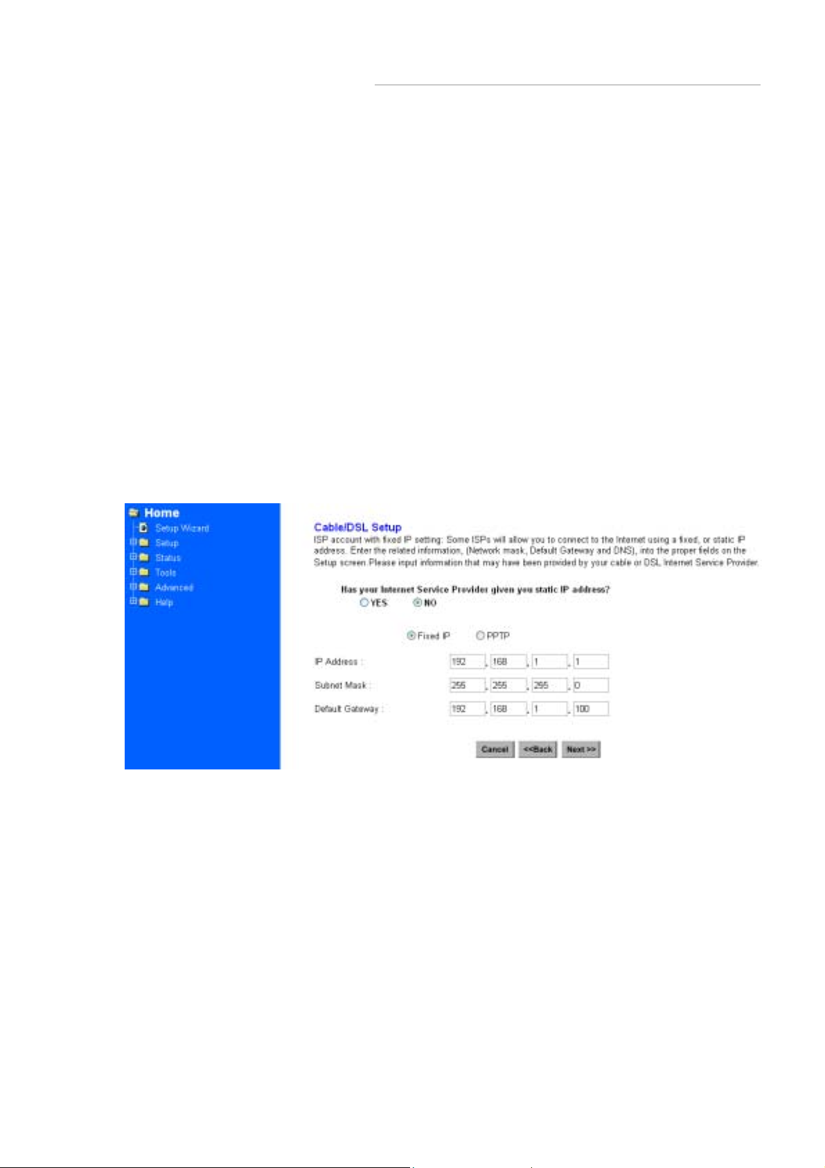
3.2.2 Fixed IP for WAN
If your ISP has assigned your home a static IP address (See Appendix A About Static
and Dynamic IP Address), you may connect to the Internet by using a fixed, or static
address. To set up a Fixed IP for WAN, do the following steps as an example.
Step 1 Choose “YES” when you see the question: (See Figure 3-5 Cable/DSL Setup
Menu with “No” Option Screen)
Has your Internet Service Provider given you static IP address?
Then select Fixed IP.
Step 2 Enter the information of IP Address, Subnet Mask and Default Gateway as
required. Then click th e “N EX T” butt on. Y ou should obtain above informati on fro m y our
ISP. If not, contact your ISP.
Figure 3-7 Cable/DSL Setup Menu
17
Page 19

Wireless Acccess Point Router
Step 3 Enter the DNS A ddress. (See Figure 3-8 DNS Menu Screen) Your ISP should
provide you with at least one DNS IP Address. If not, contact your ISP.
Figure 3-8 DNS Menu Screen
3.2.3 PPTP For WAN
Step 1 Choose “YES” when you see the question: (See Figure 3-5 Cable/DSL Setup
Menu)
Has your Internet Service Provider given you static IP address?
Then select “PPTP”.
Figure 3-9
18
Page 20

Wireless Acccess Point Router
Step 2 Click “Next>>”, and then the following screen will appear. Enter the information
of “PPTP Account”, “PPTP Password”, and “ Host Name”. “My IP Address” and ”My
Subnet Mask” assigned by your Internet Service Provider should be filled in.
Figure 3-10 PPTP Settings Screen
3.2.4 Dynamic IP for WAN
If you did not receive any values such as fixed IP address, Subnet Mask, Default
Gateway and Primary DNS IP address from your ISP, choose the “NO” option in both
Figure 3-4 Cable/DSL Setup Menu Screen and Figure 3-8 DNS Menu Screen.
Note: See Appendix A to learn more about static and dynamic IP address.
19
Page 21

Wireless Acccess Point Router
3.2.5 Alias IP Setup
The Alias IP Se tup allo w s you to enter m axi mum 5 IP ad dresses th at can be distr ibuted
to your computer . The error message will pop up i f you enter more than 5 IP address es.
See Figure 3-11 Alias IP Setup. Note that this function is effective only when your ISP
supports it. If you want to delete the entered IP address, pull down the IP address and
highlight the IP address you want to delete. Click Delete this entry. Then this IP
address will be deleted.
The application of Virtual Server and DMZ Host IP Addresses requires more than one
IP address. Alias IP provides a good support for such applications.
Figure 3-11 Alias IP Setup
20
Page 22

Wireless Acccess Point Router
3.2.6 DNS
Select the item of DNS from t he Set up menu. The follow ing screen will appe ar. Y ou can
enter the DNS Address. Your ISP should provide you with at least one DNS IP
Address. If not, contact your ISP.
Figure 3-12 DNS
21
Page 23

Wireless Acccess Point Router
3.2.7 Wireless Configuration
You can access this screen at any time by clicking the Wireless button. (See Figure
3-13 Wireless Configuration Screen)
Figure 3-13 Wireless Configuration Screen
• ESSID: All Wireless devices in your Network must use the same ESSID. Make sure
that this field reflects the correct ESSID for your network.
• Channel No: All Wireless devices in your Network must use the same ESSID. Make
sure that this field reflects the correct channel for your network. Should you experience
any interference, you may need to experiment with different channels to establish a
better connection.
22
Page 24

Wireless Acccess Point Router
• WEP:
WEP is Wired Equivalent Privacy, a data privacy mechanism based on a 40-bit or
128-bit shared key algorithm, as described in the IEEE 802.11b standard. Using a
128-bit shared key algorithm will increase network security. However, you may
experience decreased network performance when using a 128-bit shared key
algorithm. You may disable the encryption feature.
• Default Key: Select the algorithm key to be used in your 40-bit or 128-bit
WEP-enabled wireless Network.
• Encript Type: Select 40-bit or 128-bit WEP-enabled wireless Network.
• The WEP keys (1 - 4): are 10 heximal numerals for 40-bit WEP or 26 heximal
numerals for 128-bit WEP in length and can be any numeric combination. However,
these keys must be used identically for each point on your wireless Network.
• Access Control: is designed to allow or prohibit others to access through the router.
If you select “Allow Everyone Access”, everyone can access data through the router. If
you select “Only Allow Access If On This List”, then you can add new stations allowed
to access the data in the “ N ew Stations” column. You can delete the existing stations in
the “Existing Stations” column by choosing the stations you want to desert and clicking
the “Delete Stations” button.
3.2.8 Time
You can get the data of the log files by setting the time zone. (See figure3-14 Time
Zone)
Figure 3-14 Time Zone
23
Page 25

Wireless Acccess Point Router
3.3 Browsing the Status
3.3.1 Status
This screen provides the current information of the device. All of the information
provided is read-only. (See Figure 3-15 Status Menu Screen)
Router Name: You will see the na me of this device in this field.
Firmware Version: You will see the installed version of the firmware.
WAN IP Configure: This field shows whether or not you have enabled the use of
PPPoE connection, Static IP or Dynamic IP.
Firewall Settings:
-NAT allows all of the computers on your network to use one IP address.
-Hacker Attack Protect keeps you from hackers’ attack.
-DHCP server shows the status of the router’s DHCP server function.
-Block Hacker Scan makes your Router invisible so that hackers cannot find your
Router on the network.
-Remote Management allows you to manage this device from the remote site via
the network.
LAN: These fields display the c ur rent IP address and Subnet Mask of the router as
seen by the users on your internal network.
WAN: These fields display the IP Address , Subnet Mask and Default Gateway of
the router as seen by external users on the Internet. DNS (Domain Name Server)
shows the IP address of the DNS currently being used.
24
 Loading...