

Page 1

...keeping you secure
Operator’s Manual
Page 2

Page 3

...keeping you secure
Contents
General Safety Instructions........................................................................................................4
1. Appropriate Use .................................................................................................................4
2. Operator’s Duty of Care.....................................................................................................4
3. Safety Instructions..............................................................................................................5
4. Conditions of Guarantee.....................................................................................................6
Product Description.................................................................................................................... 7
1. Assembly and Product Functions.......................................................................................7
2. Environmental Conditions..................................................................................................8
3. Assembly and Set Up.........................................................................................................9
4. Commissioning.................................................................................................................11
Using the Intercom................................................................................................................... 12
1. Description of the Controls.............................................................................................. 12
2. Operating the Intercom.....................................................................................................13
2.1 Switching the Intercom On ........................................................................................ 13
2.2 Switching the Intercom to Standby Mode..................................................................13
2.3 Cancelling Standby Mode..........................................................................................14
2.4 Switching Off the Intercom........................................................................................14
3. Setting Volume and Attenuation...................................................................................... 15
3.1 Set External Volume .................................................................................................. 15
3.2 Set Internal Volume ................................................................................................... 16
3.3 Set Attenuation...........................................................................................................16
4. Special Functions ............................................................................................................. 18
4.1 Receiving Calls ..........................................................................................................18
4.2 Headset On/Off .......................................................................................................... 20
4.3 Door Opener or Switch Contact................................................................................. 20
4.4 Announcements/Paging.............................................................................................. 21
4.5 Mute ........................................................................................................................... 21
Intercom Set Up .......................................................................................................................22
1. Accessing the Set Up Menu............................................................................................. 22
2. Overview of Menu Functions........................................................................................... 23
3. Explanation of the Menu Functions................................................................................. 24
3.1 Menu function 0 - Mute ............................................................................................. 24
3.2 Menu Function 1 - Extension Mode........................................................................... 24
3.3 Menu Function 2 - External Gong Volume................................................................ 26
3.4 Menu function 3 - Internal Gong Volume.................................................................. 26
3.5 Menu function 4 - Standby.........................................................................................27
3.6 Menu function 5 - Time until Standby....................................................................... 27
3.7 Menu function 6 - Loudspeaker during Announcements........................................... 28
3.8 Menu function 7 - Headset with Loudspeaker ........................................................... 28
3.9 Menu function 8 - Set Attenuation............................................................................. 28
3.10 Menu function 9 - Number of Extensions................................................................29
3.11 Reset to Factory Settings.......................................................................................... 29
Technical Data and Connection Diagrams...............................................................................30
Overview of Components and Accessories.............................................................................. 34
Declaration of Conformity....................................................................................................... 35
3
Version 1.2
Page 4

...keeping you secure
General Safety Instructions
1. Appropriate Use
The DELTA intercom system has been specially developed for use in banks, at cash desks,
company reception areas or gatehouses, stations, night desks, ticket offices, border crossing
points, customs offices, tollbooths, currency exchanges, government offices and authorities,
and transfer locks.
The intercom system affords perfect and easy communication between the system operator
(employee) and the public (customer).
The DELTA intercom was specially developed for these purposes. It is modular in its
construction, so that it can be individually suited to the operator’s requirements and the
building’s constraints. The intercom can also be extended at a later stage with the accessories
we offer.
2. Operator’s Duty of Care
The DELTA intercom was developed and constructed in accordance with a risk analysis and
after careful selection of the applicable harmonised standards, as well as other technical
specifications. It is therefore state of the art and offers a high standard of safety.
However, this safety standard can only be achieved under operating conditions if all the
required measures are taken. It is part of the operator’s duty of care to plan these measures
and to check that they are carried out.
Please also refer to the safety instructions on the following pages.
4
Version 1.2
Page 5

...keeping you secure
3. Safety Instructions
The DELTA intercom is modular. The electrical connections between the individual
components are pre-assembled, colour-coded and pluggable. The connectors have differing
contact configurations, so that the individual leads cannot be incorrectly connected, provided
force is not used to plug them into the wrong sockets.
Any changes to the cabling must be carried out with the system switched off (take the mains
plug out of the socket).
The intercom system should only be operated with SITEC’s components and accessories.
WARNING:
The intercom MUST only be run using the mains adaptor we supply.
If a different one is used, it could cause dangerous touch voltage and electric
shocks.
The intercom must NEVER be connected directly to the mains without the
adaptor.
If another manufacturer’s products are connected and used in the intercom or in one of its
components, we cannot then guarantee the electrical safety and the operational safety of the
unit.
The intercom and its components should not be opened up under any circumstances.
The intercom and its components should be protected from extreme heat, cold and careless
handling.
The intercom has been designed for use in dry areas indoors only, although certain
components (loudspeakers, microphones) can also be operated outdoors. Please contact our
customer service for further information.
The intercom and its components must be protected from damp: no fluid should enter the
parts under any circumstances.
If the intercom or its components are brought from a cold room into a warm one,
condensation can arise. A two-hour acclimatisation period should be allowed before operating
the unit.
5
Version 1.2
Page 6

...keeping you secure
4. Conditions of Guarantee
We offer a guarantee period of two years from delivery date on all our parts. The guarantee is
limited to faults which can be attributed to material and production faults.
We regret that our guarantee does not cover faults in the intercom which have been caused by
careless or inappropriate handling.
Our guarantee is also not applicable if the intercom or its components has been repaired or
opened up by the customer.
If another manufacturer’s products are connected to the intercom, it can affect the intercom or
its components. In this case, we regret that this is not covered by our guarantee.
Our guarantee is limited to our own products and we accept no liability for consequential
damages.
Please send guarantee claims in writing directly to our customer services, together with all
DELTA intercom components.
SITEC GmbH - Customer Service
Security Products and Equipment
Johann-Georg-Herzogstraße 19
D-96369 Weißenbrunn - Hummendorf
Germany
Tel.: +49 (0) 92 61- 60 75 - 0
Fax.: +49 (0) 92 61- 60 75 - 10
mail: [email protected]
www.sitec-gmbh.de
6
Version 1.2
Page 7

...keeping you secure
Product Description
1. Assembly and Product Functions
The DELTA intercom system consists as a minimum of a central control with mains adaptor,
a main control and an extension.
The central control is the central point of the system. The electricity supply, the main control
and the extension are connected to it.
One extension can be connected directly to the central control. Up to three more extensions
can be connected to the central control using signal boosters, giving a total of up to four
possible extensions.
These details all refer to our standard central control. However, we also offer an enhanced
central control, to which one extension can be directly connected and up to seven further
extensions using signal boosters, thus offering up to eight extensions.
The intercom main control is operated by the system operator (employee).
Communication with the public (customer) is via a swan-neck microphone and a loudspeaker,
which are both integrated into the main control.
Communication is usually in full duplex mode, i.e. both sides can speak and hear at the same
time. A ‘speech balancer’ automatically controls the direction of speech, and noisy feedback
is thereby kept at a minimum.
If the building construction is particularly unfavourable, the intercom may have to be operated
in half-duplex mode or in alternating-speech mode, to avoid feedback.
The employee controls the various functions of the intercom or the connected equipment
(announcement loudspeaker, door opener).
Accessories such as a headset or an additional loudspeaker can be connected to the main
control using appropriate connectors.
In addition, various functional parameters can be modified using the main control menu, in
order to adapt the intercom to the specific operational environment.
The customer uses the extension to communicate with the employee. An extension always
consists of a microphone and a loudspeaker, but they can vary in their design and
configuration, depending on the type of extension.
Some extension designs have a call button so that the customer can call for attention. When
pressed, a gong sounds at the main control. The communication always starts on the
employee’s side, so that the customer does not have to press any other buttons.
Note: Where there are several extensions, the employee has to select the appropriate extension
with which he wishes to communicate. Simultaneous connection to several extensions is not
possible.
The extensions cannot communicate with each other either.
7
Version 1.2
Page 8

...keeping you secure
2. Environmental Conditions
The operator must ensure that the DELTA intercom is only operated when functioning
properly, and in good condition.
The room temperature for the intercom can be anywhere between –10°C und +60°C.
A wider temperature range requires a special product: please contact our customer service for
further information.
The intercom and its components should not be exposed to strong vibrations.
If the intercom or its components are brought from a cold room into a warm room,
condensation can arise. In this case, a two-hour acclimatisation period should be allowed
before the system is operated.
The intercom is only designed for use in a dry environment, although certain components
(loudspeakers, microphones) can also be operated outside. Please contact our customer
service for further information.
The intercom and its components must not be exposed to damp, and no liquids should be
allowed into the individual parts.
8
Version 1.2
Page 9
...keeping you secure
3. Assembly and Set Up
The individual components have pluggable connecting leads. The plugs are colour coded and
should be plugged into the corresponding sockets.
The connectors have a variety of contact configurations, thus preventing the individual leads
from being mixed up, provided they are not pushed forcefully into the wrong sockets.
The electrical installation of the intercom and its components should only be carried out with
mains disconnected (remove mains adaptor plug from socket).
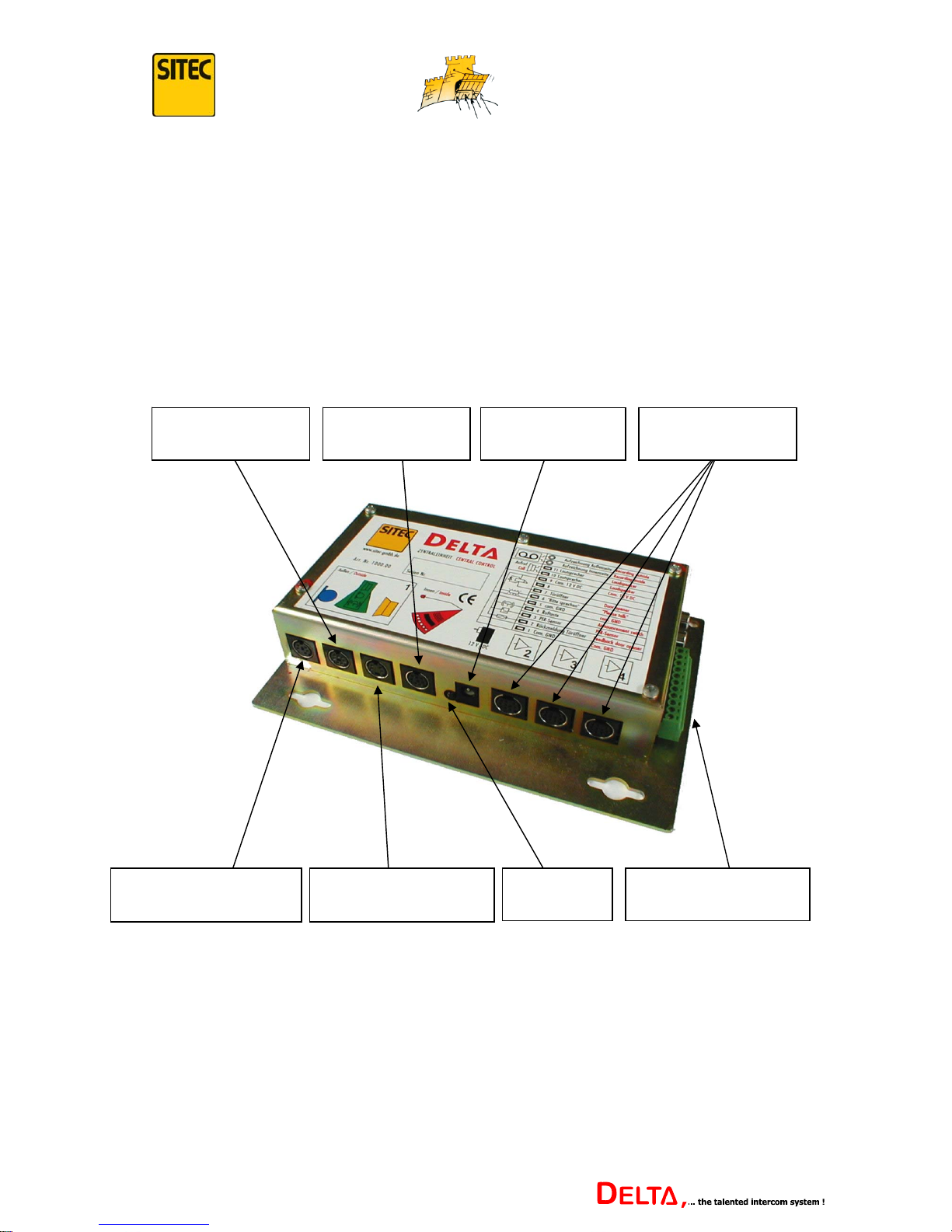
Overview of Central Control connections:
Accessory Sockets
External Loudspeaker
Socket
LED
Current
External Microphone
Socket
Extension Socket
Main Control
Socket
Mains Adaptor
Socket
Signal Amplifier
Sockets
The external loudspeaker and external microphone should be as far away from each other as
possible and should not be installed directly opposite each other, in order to avoid feedback.
The microphones should be set up or installed at speaking height if possible.
There is more information on connecting accessories (call button, door opener) from page 31
onwards.
9
Version 1.2
Page 10
...keeping you secure
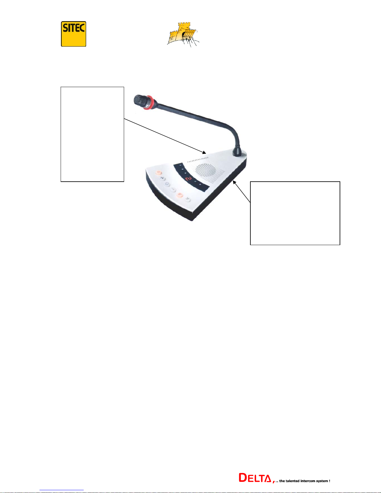
Connections to the Main Control:
Side socket for
additional
loudspeaker (the
integrated
loudspeaker is
automatically
switched off when
an additional
loudspeaker is
connected).
Side socket for headset
(consisting of earphones and
microphone which are worn
by the employee). See page
28 for further information.
The DELTA intercom has optional additional loudspeakers, wired headsets or wireless radio
headsets. Please contact our customer service or sales department for further information.
Note: Only our own original accessories should be connected to the sockets. If components
from another manufacturer are connected and operated, we cannot guarantee the electrical
safety and the operational safety of the system.
This may even lead to the intercom being damaged.
10
Version 1.2
Page 11

...keeping you secure
4. Commissioning
Once all the electrical connections have been put in place, the DELTA intercom can be
switched on. The mains adaptor should now be installed and connected.
The connecting plug on the mains adaptor should be plugged into the appropriate socket in
the Main Control (see sketch on previous page).
The mains adaptor is then connected to a socket (230V AC - 50 Hz). When the red LED
beside the mains adaptor connection is lit, it indicates that the intercom is getting current.
WARNING:
The intercom must never be connected directly to the mains without the mains
adaptor.
Once the intercom is getting current, it carries out an auto-test.
At this point, all the function buttons light up simultaneously for a brief moment and an “8”
shows in the display. This helps the operator establish if all the display elements are working
properly.
The system then carries out an automatic RESET, indicated by an “r” in the display.
Once all the buttons are extinguished and there is nothing more to be seen in the display, the
auto-test has been completed successfully.
Note: In a system with several extensions, the number of the current connection appears in the
display.
If this does not happen, there is a fault. Please check the leads on the individual components
again.
If there appears to be no fault in the wiring, the intercom should be manually reset. (See p.
29 “Reset to Factory Settings”.)
Note: When this function is carried out, all the settings changed so far are deleted and
replaced with the standard settings.
If using the “Reset to Factory Settings” function does not bring an improvement, or if this
function cannot be carried out, there may be a technical fault. In this case, please contact our
customer service.
If the intercom was started successfully, it may be necessary to change certain equipment
parameters. (Operating several extensions, or having accessories connected, changing the
operation mode, etc.)
All the possible settings are described in detail from p. 22.
The basic operating functions of the DELTA intercom system are described below.
11
Version 1.2
Page 12
...keeping you secure
Using the Intercom
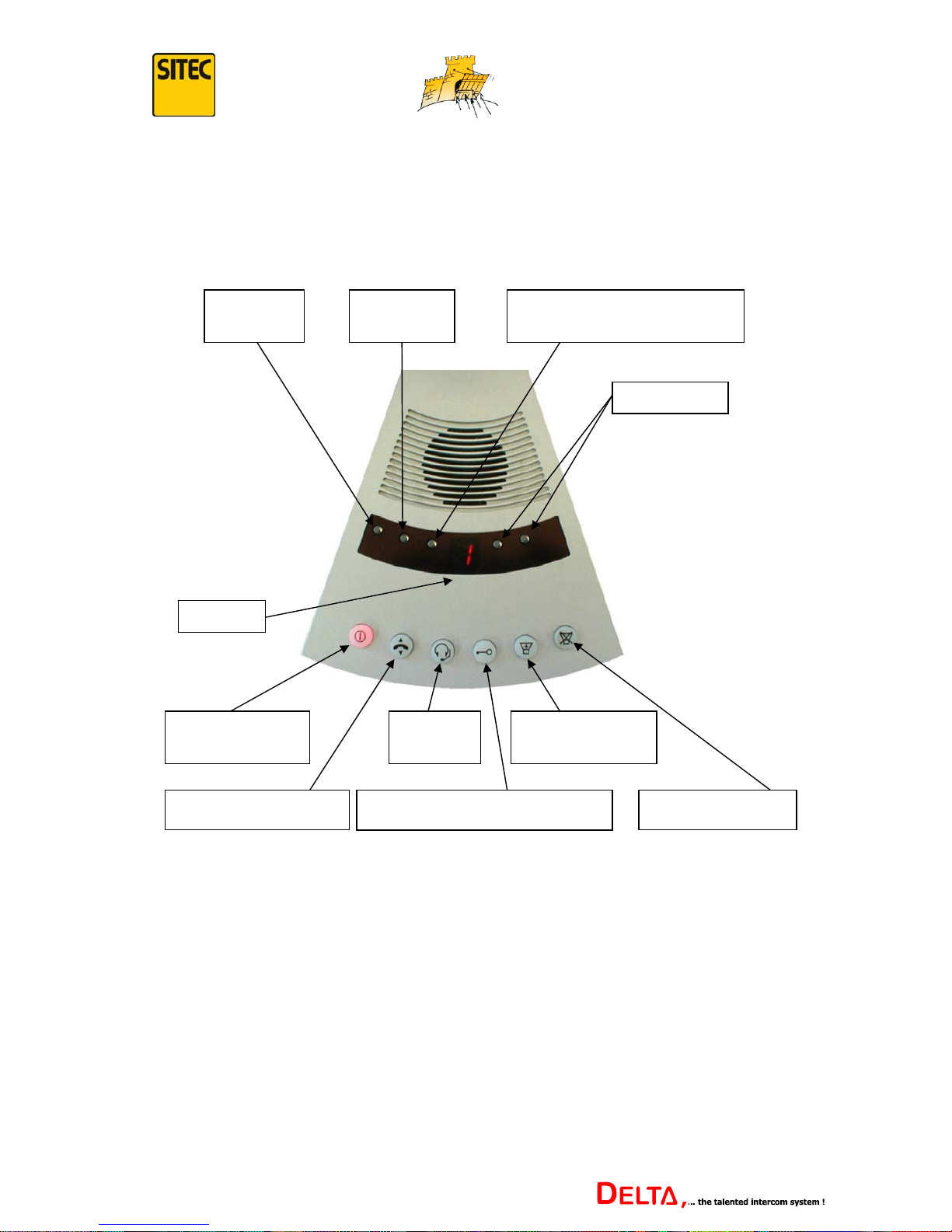
1. Description of the Controls
Display
On/Off-Standby
Button
Headset
On/Off
Announcement
(Paging)
Call Acceptance Door Opener or Switch Contact Mute
+ / - Buttons
Attenuation or Feedback
Suppression
Internal
Volume
External
Volume
12
Version 1.2
Page 13
...keeping you secure
2. Operating the Intercom
The following details refer first of all to an intercom with one main control and one extension
whose condition is as delivered.
Any operating functions which differ are explained in detail from page 18.
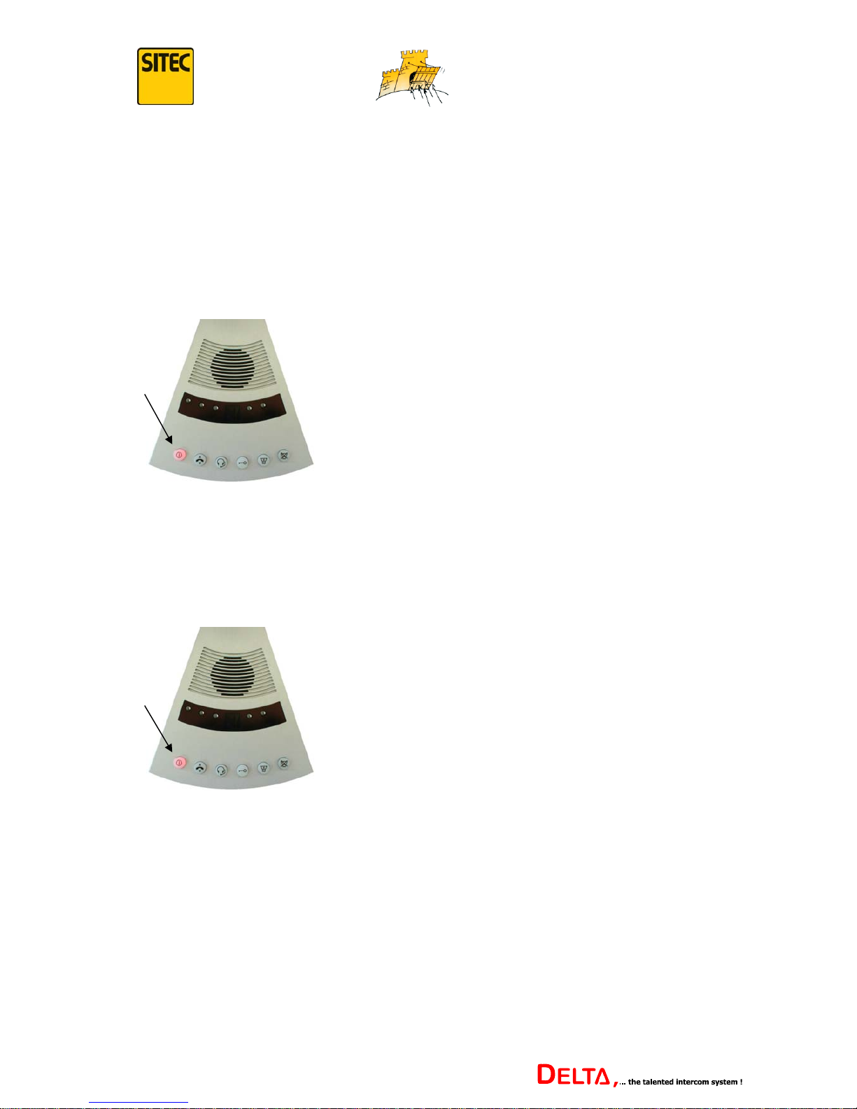
2.1 Switching the Intercom On
Briefly press the on/off button.
When the button lights up, it indicates that the system
is ready for operation.
The ring on the swan-neck microphone also lights up
as a check that it is functioning.
press
The intercom is now ready to operate and employee and customer can communicate with each
other.
2.2 Switching the Intercom to Standby Mode
press
Briefly press the on/off button.
The button light changes from a fixed light to a
flashing light, thereby indicating standby mode.
The light on the swan-neck microphone ring goes out.
The intercom is now in standby mode. Communication in both directions is interrupted and
conversations are no longer transmitted.
As the extension call button (gong) continues to operate even in standby mode, it is sensible
to use this function to switch off the intercom meanwhile, if there is no customer there. A new
customer can call the employee’s attention at any time using the call button.
The intercom can also be switched to standby mode automatically and depends on menu
function 5 in the set up menu. Further information is on page 27.
13
Version 1.2
Page 14
...keeping you secure
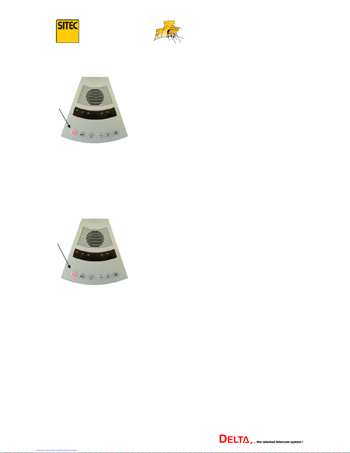
2.3 Cancelling Standby Mode
press
Briefly press the on/off button.
The button changes from a flashing light to a fixed
light, indicating that the intercom is ready to operate.
The swan-neck microphone ring also lights up to show
that it is functioning.
The intercom is now ready to operate and employee and customer can communicate with each
other. Standby mode can also be cancelled automatically and depends on the set up in menu
function 4 in the set up menu. Further information can be found on page 27.
2.4 Switching Off the Intercom
Press and
hold
Press the on/off button for longer than 2 seconds.
The light on the button goes out, indicating that the
intercom is switched off.
The light on the swan-neck microphone ring goes out.
The intercom can be switched off from either ‘on’ mode or ‘standby’ mode. This function
should be used when the intercom is not to be used for several hours, e.g. at closing time. The
intercom can be switched on again at any time by pressing briefly on the on/off button.
14
Version 1.2
Page 15
...keeping you secure
3. Setting Volume and Attenuation
The volume and attenuation levels can be increased or reduced by 16 levels each. AS the LED
only displays one digit, the 16 levels are shown in hexadecimal code.
0 - 1 - 2 - 3 - 4 - 5 - 6 - 7 - 8 - 9 - A - b - C - d - E - F
“0” is the lowest and “F” is the highest volume or attenuation.
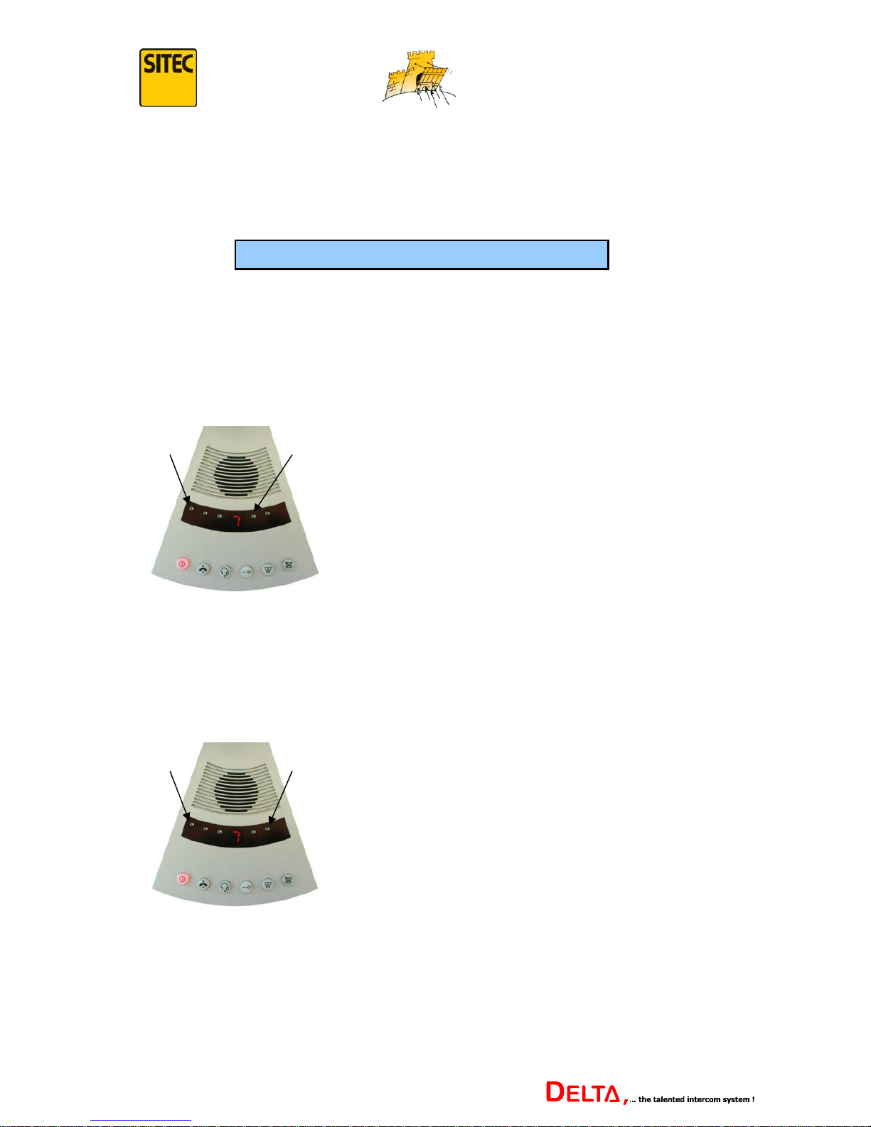
3.1 Set External Volume
Increase volume
The volume should only be increased far enough to allow clear communication, and to avoid
feedback.
Reduce volume
hold press
press hold
Hold down the “external volume” button. The
display shows the current volume level for the
extension (external loudspeaker).
Press the “+” button. Each time it is pressed, the
volume is increased by one level up to the
maximum.
Hold down the “external volume” button. The
display shows the current volume level for the
extension (external loudspeaker).
Press the “-“ button. Each time it is pressed, the
volume is decreased by one level down to the
minimum.
15
Version 1.2
Page 16
...keeping you secure
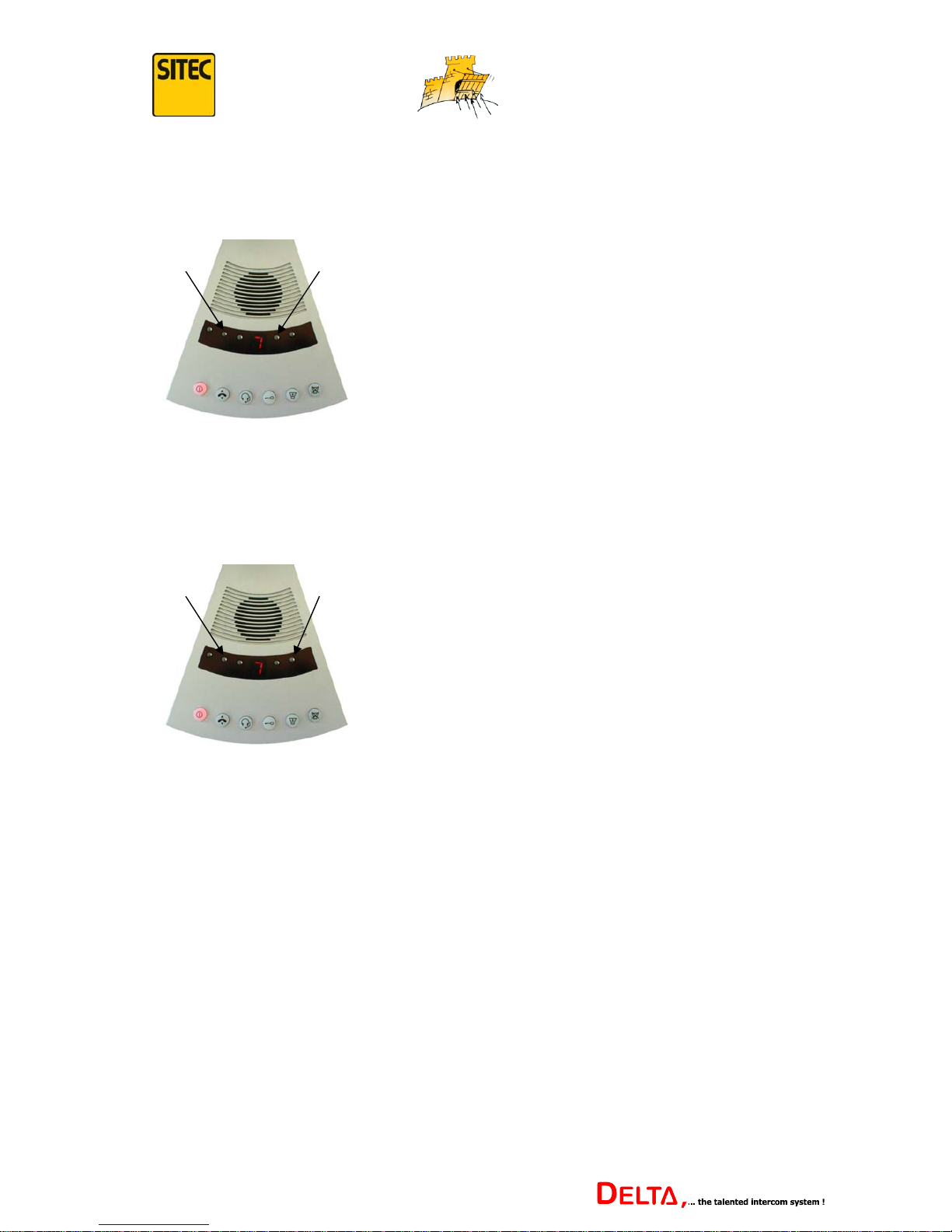
3.2 Set Internal Volume
Increase volume
The volume should only be increased far enough to allow clear communication, and to avoid
feedback.
Reduce volume
hold press
press hold
Hold down the “internal volume” button. The
display shows the current volume level for the
main control (internal loudspeaker).
Press the “+” button. Each time it is pressed, the
volume is increased by one level up to the
maximum.
Hold down the “internal volume” button. The
display shows the current volume level for the
main control (internal loudspeaker).
Press the “-“ button. Each time it is pressed, the
volume is reduced by one level down to the
minimum.
3.3 Set Attenuation
The Delta intercom uses an automatic speech equaliser.
Its intelligent electronics automatically reduce the volume of the direction of speech which is
not in use. This suppresses feedback as far as possible.
If the configuration of the intercom components is not optimum, or if the environment is not
favourable (large rooms with a lot of echo), there may be feedback nonetheless. In this case,
the speech equaliser settings will need to be changed. This is achieved by increasing the
attenuation.
Even when the volumes have been increased to improve communication, the attenuation will
usually need to be adjusted too.
The attenuation level is preset at “8” on the employee’s side and cannot initially be adjusted,
as this function is disabled. In order to adjust the attenuation level, you first have to enable
this function using menu function 8 of the set up menu. See page 28 for further information.
16
Version 1.2
Page 17
...keeping you secure
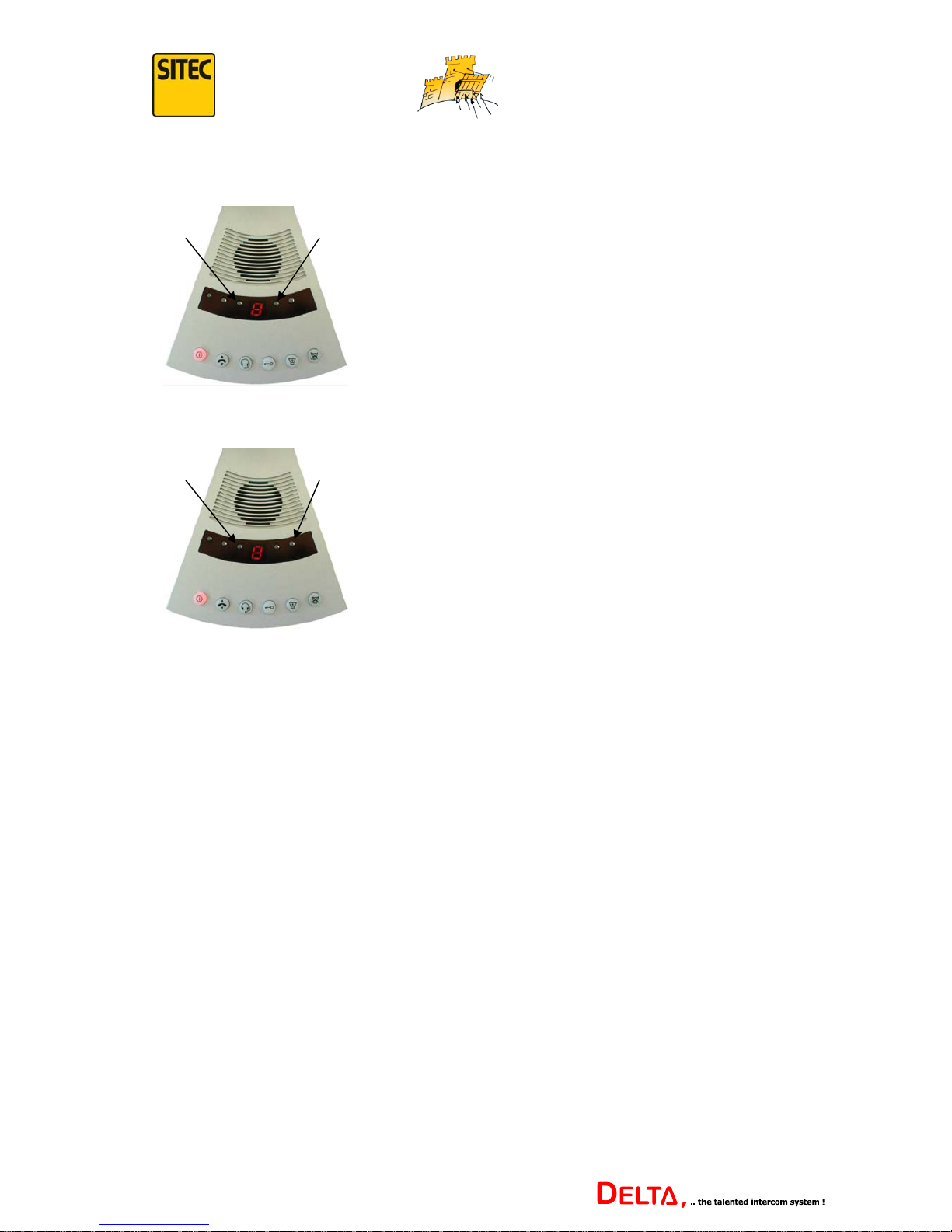
Increasing Attenuation
Reducing Attenuation
hold press
press hold
Hold down the “Attenuation” button. The display
shows the current attenuation level (preset at “8”).
Press the “+” button. Each time it is pressed, the
attenuation is increased by one level up to the
maximum.
Hold down the “Attenuation” button. The display
shows the current attenuation level (preset at “8”).
Press the “-“ button. Each time it is pressed, the
attenuation is decreased by one level down to the
minimum.
The attenuation level should only be increased far enough to achieve an optimum suppression
of feedback. The higher the attenuation level, the greater the risk that individual syllables may
be cut out of conversations.
If the maximum “F” level is reached, the system will be working in half-duplex mode. In this
case, the direction of speech not in use will be completely suppressed, which could cause
problems if people speak simultaneously at both sides.
Often, in adverse conditions, optimum communication can only be achieved if there is a
compromise between volume and attenuation.
If, in particularly adverse conditions, there is no optimum communication using the automatic
speech equaliser, the intercom can be used in alternating speech mode. In this mode only the
communication from outside inwards is active, so that the employee hears what is said on the
customer side. In order to speak to the customer, the employee has to switch the direction of
speech manually. He does this by holding down the “mute” button while he is speaking.
Alternating speech mode is activated using menu function 0 of the set up menu. Please see
page 24 for further information.
Note: In systems with several extensions, volume and attenuation and alternating speech
mode can be set up individually for each connection. If a headset is connected to the system,
the volume can also be set separately for that.
17
Version 1.2
Page 18
...keeping you secure
4. Special Functions
Depending on the DELTA intercom’s configuration (number of extensions, accessories
connected), the following functions can be carried out, using the function buttons on the main
control.
4.1 Receiving Calls
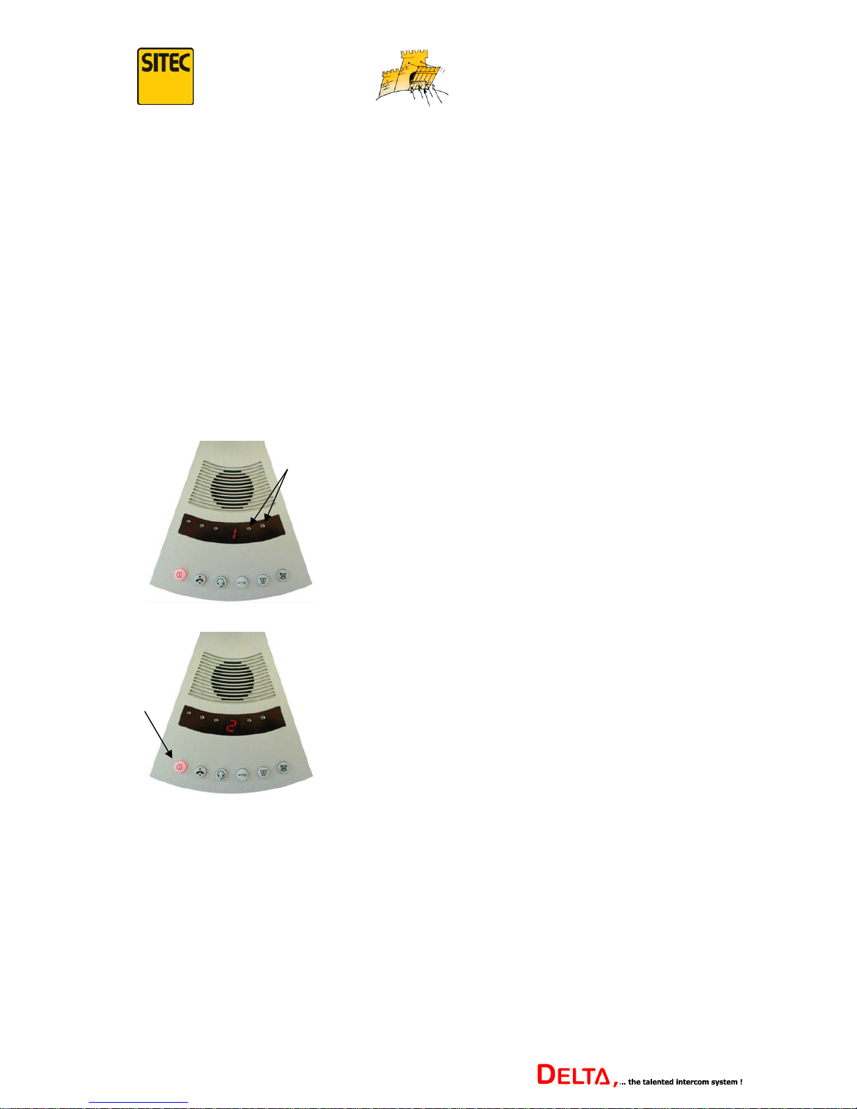
If several extensions are connected to the intercom, use the “call receive” button to connect to
a specific extension.
Note: The extensions need to have been activated using menu function 9 in the set up menu,
as otherwise there will only be a connection to the first extension. Please see page 29 for
further information.
Press the on/off button to confirm the connection
to the selected extension.
select
confirm
Use the + and – buttons to select the extension to
which a connection is to be established.
The number of the selected extension (e.g. no. “2”)
flashes faintly, alternating with the dark number of
the current connection (e.g. no. “1”).
The employee can now communicate with the customer via the selected extension. This
connection remains in place until another extension is selected using the same method.
If you do not need to switch to another extension, you can leave switch mode again by
pressing the “external volume” button. If no other button is pressed in the next 10 seconds,
then the intercom automatically leaves switch mode.
The volume and attenuation levels can be set individually for each extension. The levels set
are automatically stored and applied when a connection is made to the required extension.
18
Version 1.2
Page 19
...keeping you secure
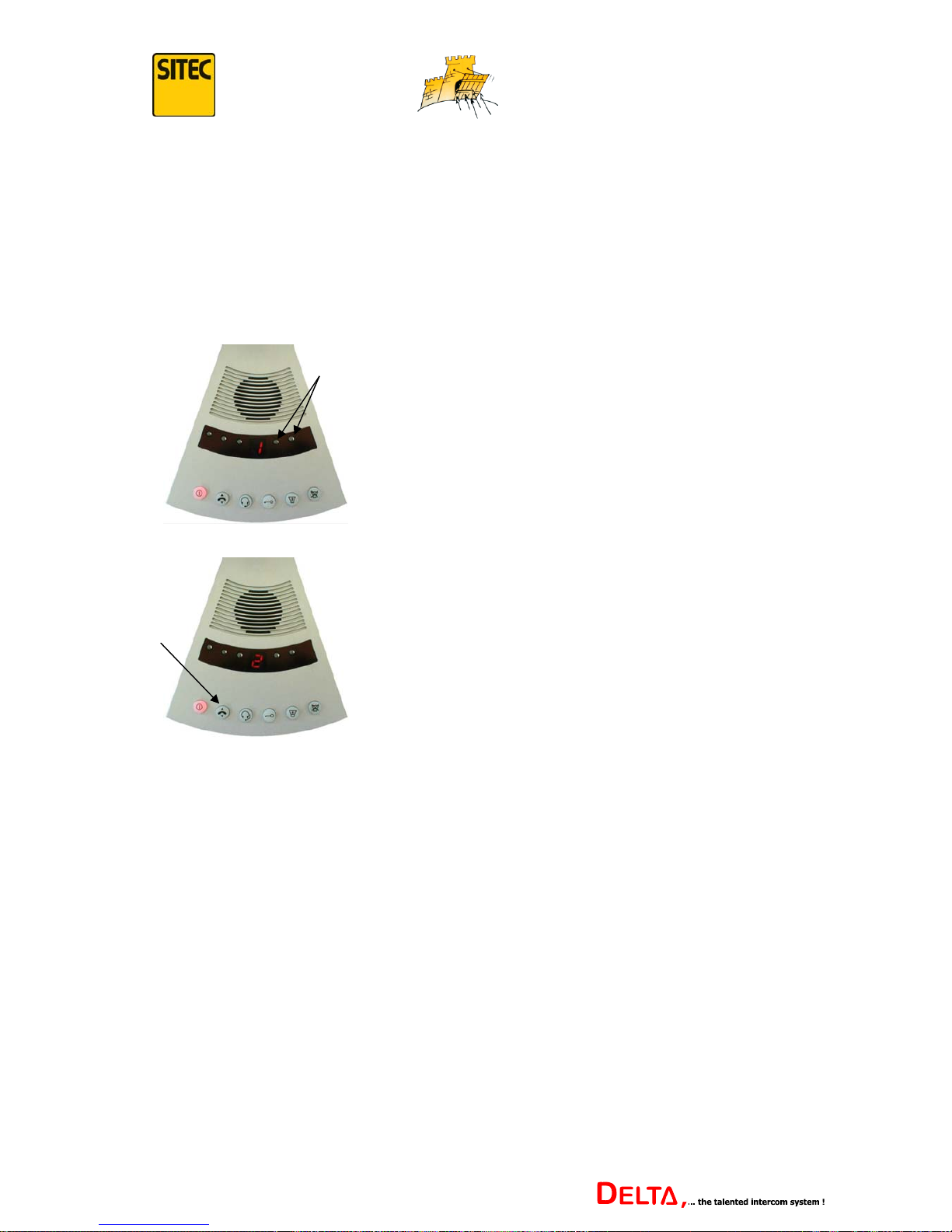
Note: If the system is in standby mode, select the extension using the + and – buttons, and by
pressing the on/off button to switch on the intercom, the connection to the required extension
can be made simultaneously.
If the employee only wants to connect briefly to another extension, e.g. to answer a quick
question by another customer and then return to the first customer, this can be done as
follows:
select
Use the + and – buttons to select the extension to
which you wish to connect briefly.
The number of the extension selected (2) flashes
lightly, alternating with the dark number of the
current connection (1).
confirm
By pressing the “call receive“ button, the existing
connection is temporarily interrupted and you are
connected to the selected extension.
Pressing the button again returns you to the
original connection.
The employee and customer at the second extension can communicate with each other after
the button is pressed. The customer at the first extension cannot listen into the conversation.
When the button is pressed again, the employee can speak with the first customer again.
It is not possible to communicate with both customers simultaneously.
If the call button is pressed on an extension, a gong usually sounds on the loudspeaker of the
main control. This depends on the set up of menu function 3 in the set up menu. Please see
page 26 for further information.
The number of extension calling flashes lightly for a while in the LED display, alternating
with the dark number of the current connection.
Just as with selecting the extension, a permanent connection can be made by pressing the
on/off button, or a temporary one by pressing the “call receive” button.
19
Version 1.2
Page 20
...keeping you secure
4.2 Headset On/Off
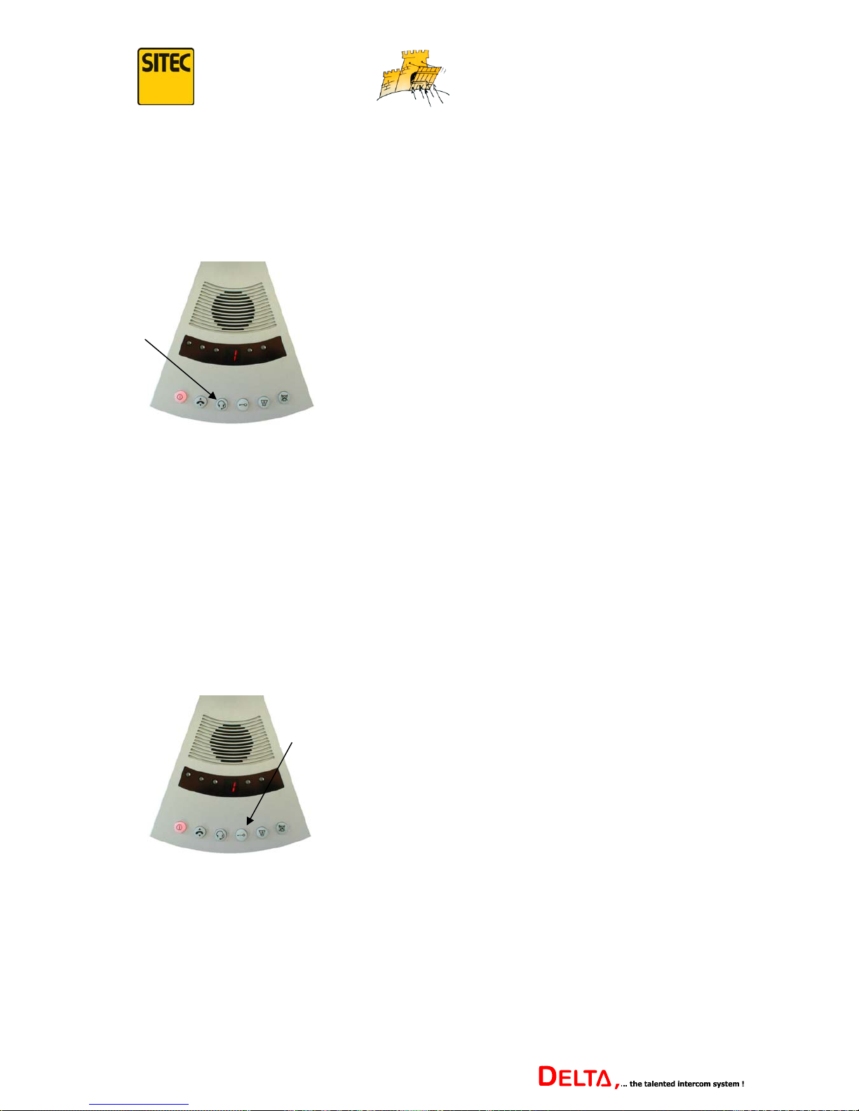
If there is a headset connected to the main control of the Delta intercom (consisting of
earphones and microphone, worn by the employee), you can switch to headset operation by
pressing this button. Pressing on this button again returns you to normal operation.
Note: The swan-neck microphone integrated in the main control is always switched off when
the headset is operating. You can select to hear the customer’s reply, however, either through
the earphones or the main control’s loudspeaker. The setting in question is carried out using
menu function 7 in the set up menu, and for further information see page 28.
4.3 Door Opener or Switch Contact
A switch contact is available on both the main control of the Delta intercom and the extension
signal amplifiers (See p.31ff for description of connection). This switch contact allows you to
e.g. control a door opener. When the “door opener/switch contact” button is pressed, the
switch contact controls the connected function for about 3 seconds.
press
press
Press the “Headset On/Off” button to switch the
intercom to headset operation.
Pressing this button again returns you to normal
operation.
When the “door opener/switch contact” button is
pressed, the connected function, e.g. a door opener,
is controlled for about 3 seconds.
Note: If the door opener also has a feedback signal connected, the button flashes when the
door is open. Further information on connecting the feedback contact is on page 32.
20
Version 1.2
Page 21
...keeping you secure
4.4 Announcements/Paging
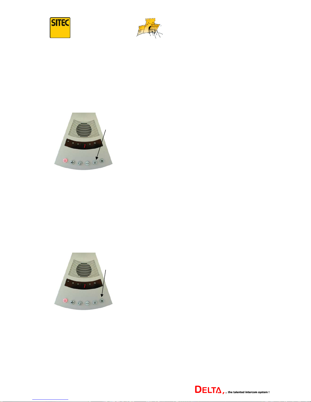
For as long as this button is pressed, either the volume to the extension which is connected at
that time is increased, or you are switched to a separate paging loudspeaker, which may e.g.
be in a waiting room.
This depends on the configuration of menu point 6 in the set up menu; further information is
on page 28.
This function allows the employee to make an announcement or to call the next customer.
4.5 Mute
This button allows the employee temporarily to mute communication from inside to out, so
that the customer cannot hear what is being said on the inside. Mute is activated either by
pressing the button briefly, or for as long as the button is held down. This depends on the
configuration of menu function 0 in the set up menu; further information can be found on
page 24.
This button can also be used to speak by the employee when the intercom is in alternating
speech mode.
As long as the “Announcements/Paging” button is
pressed, either the volume of the extension
increased, or the announcement goes via a separate
loudspeaker, which could e.g. be in a waiting room.
hold
press or
hold to
speak
Pressing the “mute” button halts communication
between inside and outside. Pressing the button
again cancels the mute.
In alternating speech mode, the employee can use
this button to speak.
21
Version 1.2
Page 22
...keeping you secure
Intercom Set Up
1. Accessing the Set Up Menu
The Delta intercom has a set up menu in order to be best suited to the local operating
conditions.
The set up menu is divided into 10 menu functions (0-9).
The first 4 menu functions (0-3) can be set up separately for each extension.
This means that the connection to the appropriate extension must be selected before calling up
the set up menu. Menu functions 4-9 are the same for all extensions. If they are to be changed,
it is immaterial which extension is connected at that moment.
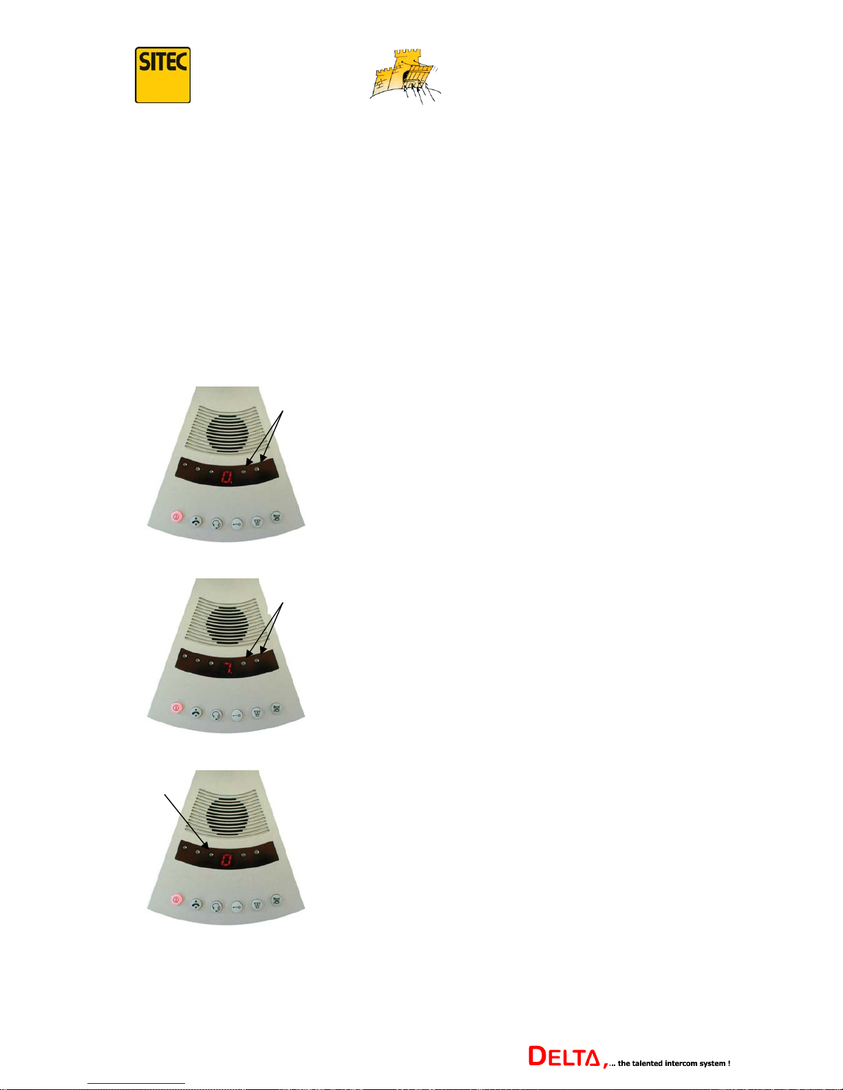
To access the set up menu and make changes, the following steps should be followed:
press
simultaneously
Press the + and – buttons simultaneously for
about 2 seconds.
A “0” appears in the LED display with a
flashing dot.
select
The individual menu functions can be selected using
the + and – buttons.
The menu function in question is indicated by the
number (in this case “7”) and the flashing dot.
confirm
To call up the set up of the menu function in
question, press the “attenuation” button.
The LED display now shows the chosen value (in
this case “0”), and the flashing dot is no longer
shown.
22
Version 1.2
Page 23
...keeping you secure
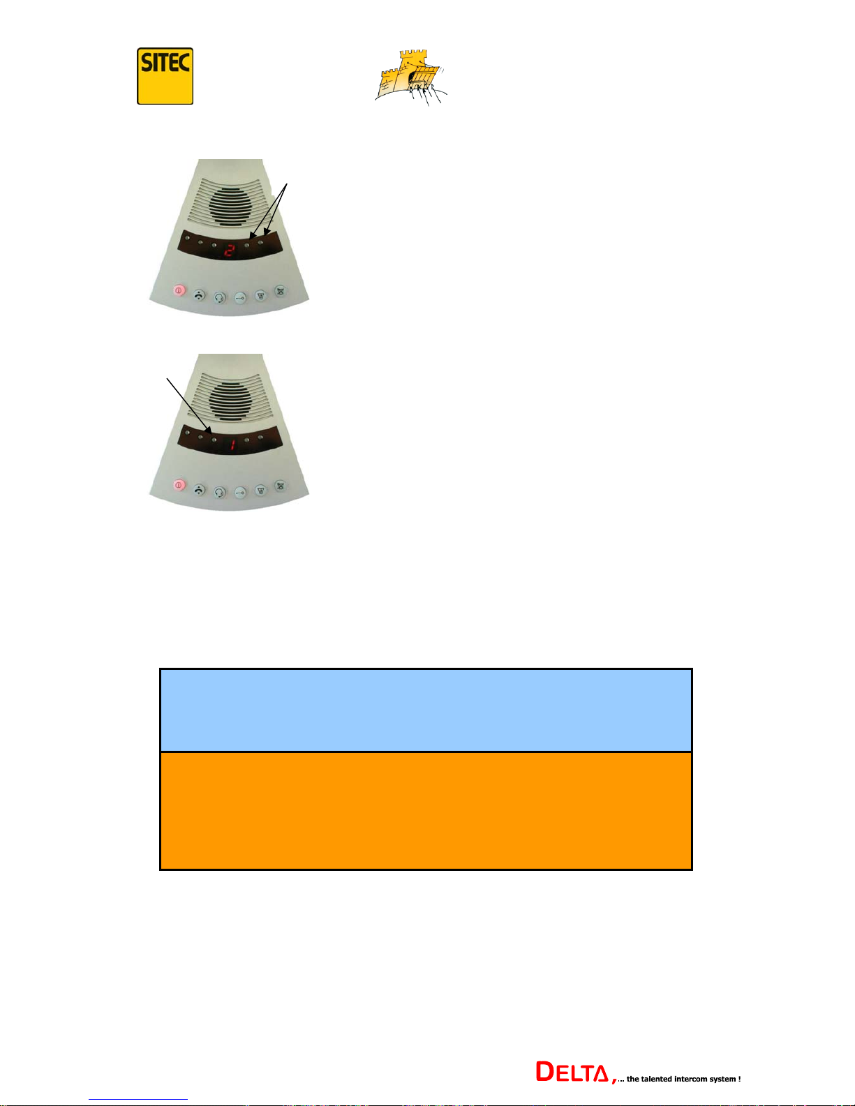
select
The value can now be modified using the + and –
buttons (in this case from “0” to “2”).
confirm
Press the “external volume” button to leave the
menu function. The value selected will thereby be
adopted and stored.
The intercom returns to normal operating mode,
and the current connection is shown in the LED
display.
If no buttons are pressed within 10 seconds, the intercom automatically switches back to
normal operating mode, and this way modified values are also stored.
2. Overview of Menu Functions
0: Mute These menu functions can be set
1: Extension Mode individually for each extension
2: External Gong Volume connection.
3: Internal Gong Volume
4: Standby These menu functions apply equally
5: Time until Standby to all connections to the
6: Announcement Loudspeaker individual extensions.
7: Headset with Loudspeaker
8: Attenuation adjustment
9: Number of Extensions
23
Version 1.2
Page 24

...keeping you secure
3. Explanation of the Menu Functions
The following explains the individual menu functions in detail.
The value in bold is the status at delivery.
3.1 Menu function 0 - Mute
This menu function adjusts the settings for the “mute” button.
This function can be set separately for each extension.
0: Press this button to mute sound from inside to outside.
Press again to cancel mute.
1: Communication from inside to outside is muted as long as button is held
down.
2: Alternating speech mode: Only communication from outside to inside is
activated. When the button is pressed, communication is switched to
inside to outside.
3.2 Menu Function 1 - Extension Mode
This menu function sets the intercom for the type of extension in question (extension with
microphone and loudspeaker, or extension with telephone receiver).
With this menu function, you must first select whether the extension is connected directly to
the central control or through an extension amplifier.
In the case of an extension which is connected directly to the central control, the following
settings should be used.
Setting: Extension type:
0: Extension with microphone and loudspeaker
1: Extension with tele
p
hone receive
r
In the case of an extension with telephone receiver, setting “1” means that the communication
link is only activated once the receiver has been lifted. The message “please speak” is
displayed simultaneously. When the receiver is put down, the communication is muted again.
If the intercom is in standby mode, a gong tone is sounded in the main control’s loudspeaker
when the telephone receiver is lifted.
(Note set up of menu function 3 - Gong internal volume, see page
26.)
Note: The settings “0” and “2”, and settings “1” and “3” are identical in this case.
24
Version 1.2
Page 25

...keeping you secure
In systems with several extensions which are connected through signal amplifiers, this menu
function is a little more complex.
As each signal amplifier only has one switch output and one switch input, the way these
connections function must be set using this menu function.
The switch output can e.g. either light up the “please speak” message display at the extension
or control a door opener connected to the signal amplifier.
If a bell button has been connected to the switch input, the hook switch function on extensions
with a telephone receiver will not be available.
This menu function can be set separately for each extension.
Brief summary of the possible settings:
Setting: Switch Output Function: Bell Input Function:
0: “Please speak” display Bell button
1: “Please speak” display Telephone receiver hook switch
2: Door opener Bell button
3: Door opener Telephone receiver hook switch
Explanation of the possible configurations:
0: The message display “please speak” is activated at the extension as soon
as the main control connects to it. If a bell is pressed at the extension, a
gong sounds in the loudspeaker of the main control.
1: The message display “please speak” is activated at the extension as soon
as the main control connects to it. If the extension has a telephone
receiver and it is lifted, a gong sounds in the loudspeaker of the main
control.
2: Pressing the “door opener/switch contact” button at the extension
activates the switch output for about 3 seconds. The message “please
speak” is displayed at the same time. If the bell button is pressed at the
extension, a gong sounds in the loudspeaker of the main control.
3: Pressing the “door opener/switch contact button at the extension activates
the switch output for about 3 seconds. The message “please speak” is
displayed at the same time. If the extension has a telephone receiver and
it is lifted, a gong sounds in the loudspeaker of the main control.
25
Version 1.2
Page 26

...keeping you secure
3.3 Menu Function 2 - External Gong Volume
This menu function allows the external gong function to be set.
This function can be set up separately for each extension.
0: When the “Announcements/Paging” button is pressed, there is no gong
sound in the announcement or extension loudspeaker.
1: When the “Announcements/Paging” button is pressed, there is a soft
gong sound in the announcement or extension loudspeaker.
2: When the “Announcements/Paging” button is pressed, there is a loud
gong sound in the announcement or extension loudspeaker.
3.4 Menu function 3 - Internal Gong Volume
This menu function sets the gong function on the inner side.
This function can be set separately for each extension.
0: When the extension bell button is pressed, there is no gong sound at the
loudspeaker of the main control. The display simply shows the number
of the extension calling, which alternately flashes lightly against the dark
number of the current connection.
1: When the extension bell button is pressed, a soft gong sounds at the
loudspeaker of the main control. In addition, the number of the extension
calling alternately flashes lightly against the dark number of the current
connection.
2: When the extension bell button is pressed, a loud gong sounds at the
loudspeaker of the main control. In addition, the number of the extension
calling alternately flashes lightly against the dark number of the current
connection.
26
Version 1.2
Page 27

...keeping you secure
3.5 Menu function 4 - Standby
This menu function can be used to cancel the standby function.
This function applies to all the connections to the individual extensions.
0: No standby function
1: The standby function can only be cancelled using the on/off button.
2: The standby function can either be cancelled using the on/off button or if
someone is speaking externally.
In addition to speech recognition, a proximity switch connected to the
central control signals that a customer is in range.
3: The standby is either cancelled using the on/off button or if someone is
speaking externally.
3.6 Menu function 5 - Time until Standby
This menu function is used to activate the standby function.
This function applies equally to all connections to the individual extensions.
0: Standby function is only activated using the on/off button
1: The intercom automatically switches into standby mode if noone has
spoken on either side for more than 30 seconds.
2: The intercom automatically switches into standby mode if noone has
spoken on either side for more than 60 seconds.
3: The intercom automatically switches into standby mode if noone has
spoken on either side for more than 120 seconds.
4: The intercom automatically switches into standby mode if noone has
spoken on either side for more than 300 seconds.
27
Version 1.2
Page 28

...keeping you secure
3.7 Menu function 6 - Loudspeaker during Announcements
This menu function is used for setting whether the extension volume is increased when the
“Announcements/Paging” button is pressed, or whether the announcement should be
channelled through a separate announcement loudspeaker.
If the function has been activated, announcements always go through a separate
announcement loudspeaker, regardless of the extension to which you are currently connected.
It is not possible to activate announcements through the loudspeaker of the individual
extension, even if the “Announcement/Paging” button is pressed.
If this function is disabled, announcements can be directed to each extension individually.
0: Announcement goes through the loudspeaker of the extension to which
you are currently connected, with increased volume.
1: Announcement goes exclusively through a separate announcement
loudspeaker.
3.8 Menu function 7 - Headset with Loudspeaker
This menu function controls whether the customer’s voice sounds in the earphones or in the
loudspeaker of the main control when a headset is being used. The swan-neck microphone at
the main control is always switched off when a headset is used.
This function applies equally to all the connections to the individual extensions.
0: The customer’s reply is heard through the headset earphones.
1: The customer’s reply is heard on the loudspeaker of the main control.
This function gives the option of connecting a
lapel microphone or a neck microphone.
3.9 Menu function 8 - Set Attenuation
This menu function sets whether the attenuation can be modified.
This function should usually always be disabled so that the attenuation cannot be altered
unintentionally.
This function applies equally to all the connections of the individual extensions.
0: Attenuation cannot be set (disabled).
1: Attenuation can be set.
28
Version 1.2
Page 29
...keeping you secure
3.10 Menu function 9 - Number of Extensions
This function is used to set the number of extensions which are connected.
A maximum of 8 extensions can be connected. The appropriate number of extensions is
entered directly as a numerical value.
The factory setting is “1” for one extension.
3.11 Reset to Factory Settings
The DELTA intercom can be reset to the original factory settings at any time.
To reset to factory settings, the following procedure should be carried out.
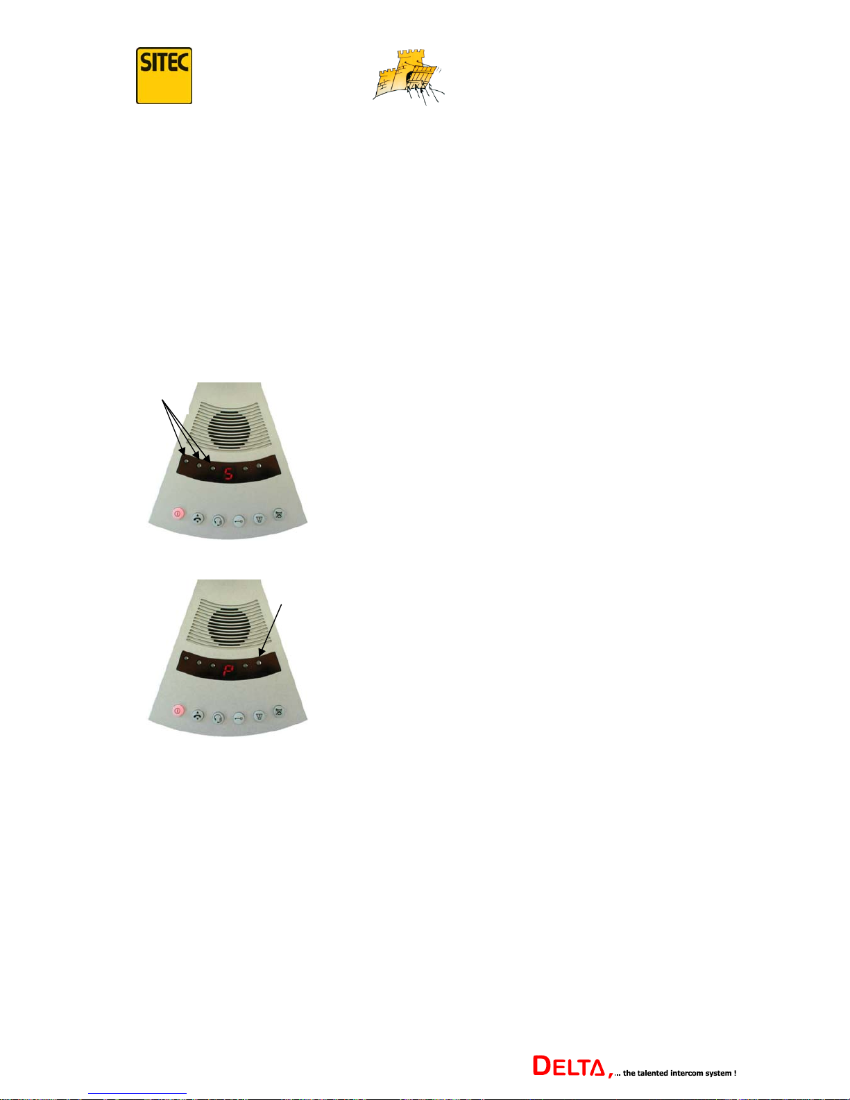
Press
simultaneously
Press the external volume, internal volume and
attenuation buttons simultaneously for about 3
seconds.
The letters “S” and “P” flash alternately in the
LED display.
press
Briefly press the + button.
The system is now reset to the factory settings.
Note: If there are several extensions connected to the intercom, the number of extensions
must be re-entered in the set up menu using menu function 9 (see previous menu function).
29
Version 1.2
Page 30
...keeping you secure
Technical Data and Connection Diagrams
Technical Data:
Supply voltage: 230 Volts AC / 50 Hz
Operating voltage: 12 Volts DC
Max power output: 4 Watts per circuit
Temperature range: -10 to +60° Celsius
Relative humidity: < 90% non-condensing
Non-volatile memory (all data input remain in the memory, even if there is a power cut)
Electret microphones
16-stage volume control which can be set separately for outside and inside
16-stage feedback suppression
Connection of Accessories:
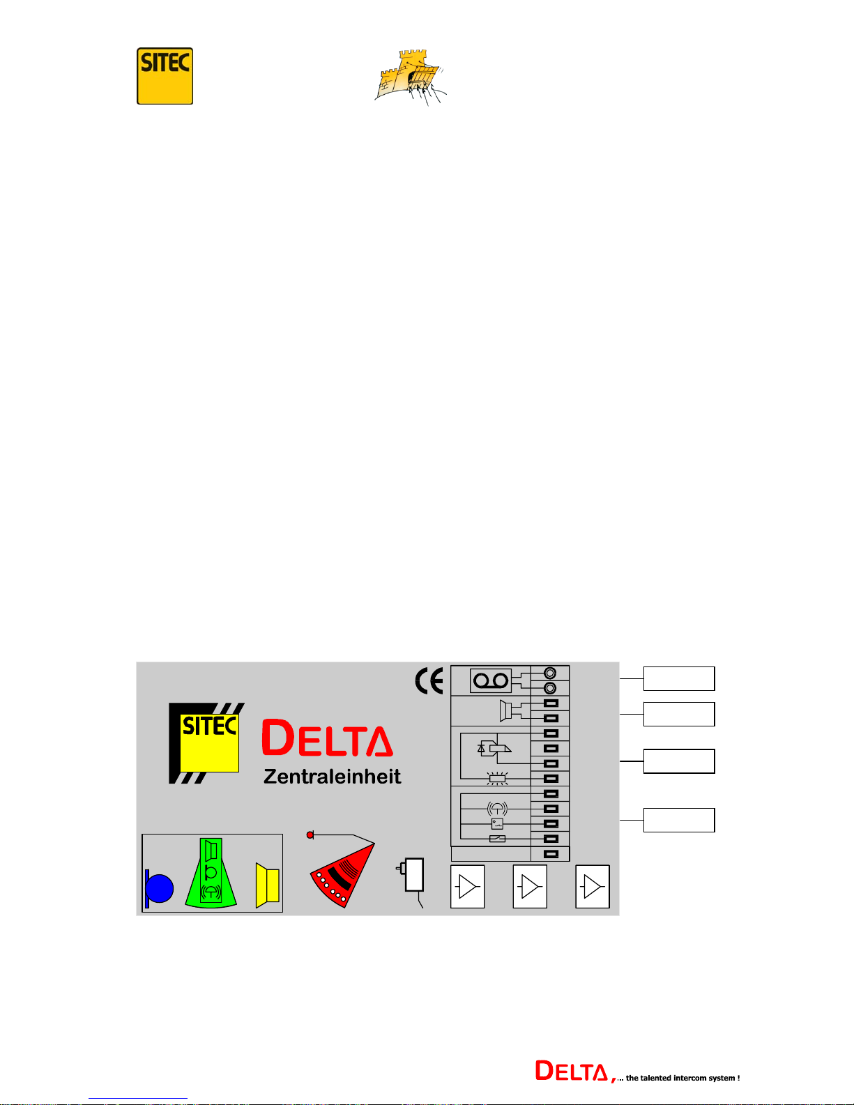
The central control of the DELTA intercom has connections for accessories.
Warning: Only our own original accessories should be connected to connection points 3 and
4.
If accessories or equipment from another manufacturer are connected to the intercom or any
of its components, it may in the worst case destroy the intercom or its components. Our
guarantee will unfortunately not be applicable in these circumstances.
For further information on connecting accessories, please contact our Customer Services.
1
234
Aufruf
com. 12V DC
La utsp re ch e r
Aufzeichnung
Aussenseite
Aufzeichnung
Innenseite
La utsp re ch e r
Re se r v e
Türöffner
"Bitte sprec hen"
com. GND
com. GND
Ruftaste
PIR- Se n so r
Rüc km e l d u n g
Türöffner
Point 1
Point 3
Point 4
The possible individual connections are described in detail below.
30
Version 1.2
Page 31

...keeping you secure
Point 1 - Connecting a Recording Device
It is possible to record the conversations held on the DELTA intercom on a standard trade
audiocassette using a recording device.
The conversations from outside and inside can be recorded separately on the two stereo tracks
of the audiocassette. We recommend a recording device with speech control, which
automatically stops recording when nothing is being said.
Point 2 - Connecting an Additional Announcement Loudspeaker
An additional announcement or paging loudspeaker can be connected to the central control of
the DELTA intercom. The loudspeaker output needs to be activated using menu function 6 in
the set up menu (see also page 28).
If the “announcement” button is now pressed on the main control, the message is relayed over
the additional loudspeaker. The loudspeaker should show an impedance of minimum 4Ω and
a capacity of minimum 5 watts.
Note: If the Announcement Loudspeaker menu function has been activated, then all
announcements will be made through the separate announcement loudspeaker, regardless
which extension is connected at that moment. It is not possible to activate announcements
through the loudspeaker at the individual extension, even if the “Announcement/Paging”
button is pressed.
If this function is disabled, announcements can be targeted to each individual extension.
Point 3 - Connecting a Door Opener and “Please Speak” Message Display.
A door opener and a message display can be connected to the central control of the DELTA
intercom. If the “Door Opener” button on the main control is pressed, the door opener is
controlled for about 3 seconds.
Warning: Only door openers supplied by Sitec should be used. A door opener from other
sources may overload and destroy the output level by too high a current consumption.
An external message display with “please speak” can also be connected. This lights up as
soon as a connection is made to extension 1.
31
Version 1.2
Page 32
...keeping you secure
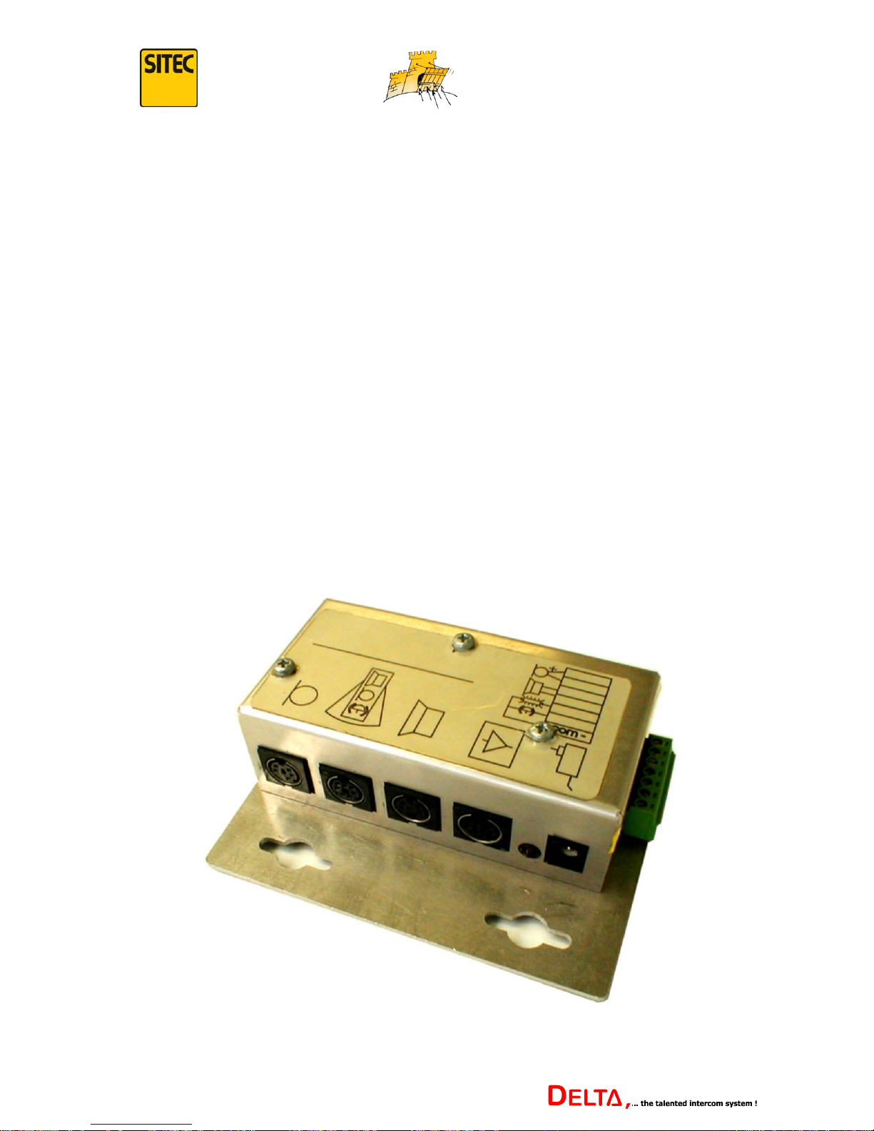
Point 4 - Connecting a Call Button, Infrared Movement Detector and the Feedback Contact.
A call button, an infrared movement detector and the feedback contact of the door opener can
be connected to the central control of the DELTA intercom.
When the call button is pressed, a gong tone sounds in the loudspeaker of the main control
(depending on the set up of menu function 3 in the set up menu – please see page 26 for
further information) and the pale number of the extension calling flashes in the LED display,
alternating with the dark number of the current connection.
The infrared movement detector is used to determine if someone is standing within speech
range of the extension. Depending on the set up of menu function 4 in the set up menu, the
intercom can be switched on again automatically from standby mode (see also page 27).
If a door opener with a feedback contact is used, you can query if the door is open or closed.
The feedback contact should be connected in such a way that input is switched to minus
(GND) when the door is open. When the door is open, the “Door Opener/Switch Contact”
button now flashes.
The Signal Amplifier:
An extension can be directly connected to the central control. Further extensions are
connected via the signal amplifier, as shown in the following picture. Each additional
extension requires a separate signal amplifier.
Every signal amplifier should be supplied by its own mains connector and voltage.
32
Version 1.2
Page 33
...keeping you secure
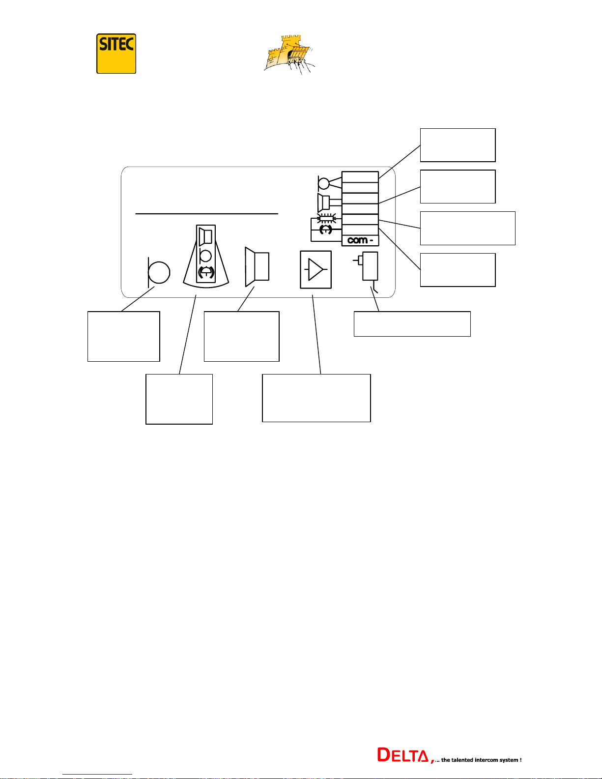
The signal amplifiers also have connectors for accessories.
+
Microphone
plug
Extension
plug
Loudspeaker
plug
Power supply
Loudspeaker
connection
Microphone
connection
Message display
connection
Call button
connection
Connection for
connecting lead to
central control
Complete extensions can be connected at the signal amplifier using the available plugs. In
addition, it is possible to connect the loudspeaker and microphone via the plugs or directly via
the screw terminals.
It is also possible to connect a call button and a “please speak” message display.
When the call button is pressed, a gong tone sounds in the loudspeaker of the main control
(depending on the set up of menu function 3 in the set up menu – see page 26 for further
information) and the number of the extension calling flashes lightly against the dark number
of the current connection in the LCD display.
The message “please speak” is displayed as soon as a connection is made to the extension.
33
Version 1.2
Page 34
...keeping you secure
Overview of Components and Accessories
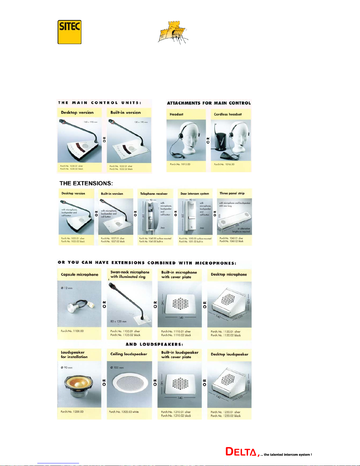
The following components and accessories are available:
34
Version 1.2
Page 35
...keeping you secure
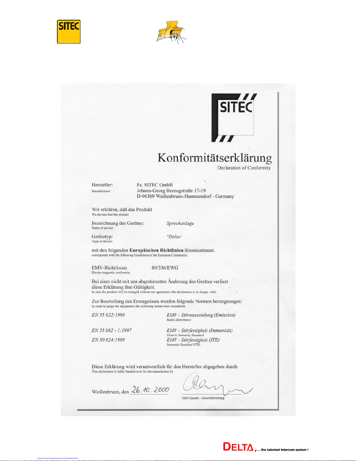
Declaration of Conformity
35
Version 1.2
Page 36

...keeping you secure
Notes:
36
Version 1.2
Page 37

...keeping you secure
Notes:
37
Version 1.2
Page 38

...keeping you secure
Notes:
38
Version 1.2
Page 39

...keeping you secure
Notes:
39
Version 1.2
Page 40

Status: October 2007
Author: SITEC Sales/Tech. dept.
Translation: Hilary Swanston
E&OE © Sitec GmbH
This document, or its constituent parts, may not be reproduced without our express permission.
 Loading...