

Sisis AUTO-ROTORAKE Mk.5, ARR/5, 8432 29 10 Instruction Manual

AUTO-ROTORAKE Mk.5
INSTRUCTION MANUAL
SP20008_REV3
MAY 2018

2
CERTIFICATE OF CONFORMITY
Auto-Rotorake CN Code: 8432 29 10
Manufacturer:- Howardson Ltd, Howardson Works, Kirk Langley , D erby , DE6 4N J. UK
Owner of Technical Document:- Mr I.D. Howard, Howardson Ltd, Howardson Works Kirk Langley, Derby, DE6 4NJ, UK
I the under signed Declare that these machines:-
The reliability and quality of performance of the SISIS Auto-rotorake depends upon some simple care maintenance
carried out regularly. This manual has been prepared to allow the user to carry out all such work.
It is advisable to read the instructions carefully . Proper care and attention w ill enable the machine to give a continuous,
satisfactory, and reliable serv ice. F ailure to carry out regular lubr ication and maintenance as outlined in this manual may
render any guarantee or warranty invalid.
In the case of any difficulty, or if further information or advice is required, our Service Depart ment is always at your call. In
the interests of speed and accuracy of information please quote the serial numbers of the machine and engine when
making enquiries.
For the machine, this is to be found on a plate attached to the side frame. T he engine number is stamped
on either the crank case or the gear casing facing tow ards the fr ont of the machine. We suggest you write
the numbers on the front page of this book.
INTRODUCTION
SERIAL NUMBERS
Ian Howard
Tested at:- Howardson Works test site September 2011
Complies with the applicable requirements of:-
- Machine Directive 2006/42/EC
- Noise Directive 2000/14/EC (Annex VI Procedure 1)
Managing Director
MODEL OPERATING
WIDTH
POWER
(HONDA)
MEASURED SOUND
POWER LEVEL
GUARANTEED SOUND
POWER LEVEL
SERIAL
NUMBER
ARR/5 20” (510MM) GX160 79dB Lwa 98dB Lwa See Product ID
range
ENGINE SERIAL NUMBER
MACHINE SERIAL NUMBER
NOTE:- MAKE A NOTE OF THE SERIAL NUMBERS OF YOUR MACHINE & ENGINE AND ALWAYS
QUOTE THEM IN ANY COMMUNICATION WITH PERSONNEL AT DENNIS.
SP20008_REV3
MAY 2018

3
CONTENTS
IMPORTANT SAFETY INTRODUCTIONS
TECHNICAL DATA
WARNING:- WHEN WORKING WITHOUT THE GRASS BOX, LOW E R THE DEFLECTOR TO PROTECT
THE OPERATOR AND ENGINE AIR INTAKE FROM FLYING DEBRIS.
CAUTION:- READ THE INSTRUCTIONS CAREFULLY AND ALSO THE SEPARATE INSTRUCTION
DETAILS ON THE ENGINE..
NEVER
• carry out adjustments with the engine r unning.
ALWAYS
• read the operating instructions carefully and understand the controls before commencing work.
• be extra careful to avoid spillage, when using petrol or diesel fuel. DANGER no smoking or naked lights
• use safety guards and make sure they are correctly in position. they are supplied for your protection
• visually check machines before starting work for damage or wear to working parts such as blades,tines or loose fasteners
• respect powered machines. alw ay s keep hands and feet clear of moving par ts and remember that tine cylinders or
drums can continue to rotate even after the power unit is switched off
• switch off the power before making adjustments or repairs and never lift or carry a machine whilst any parts are
Moving
EYE PROTECTION
In dry, dusty or windy conditions it may be necessary to wear eye protection to protect your eyes from fly ing debris.
FIRE HAZARD
ALWAYS CLEAN THE MACHINE. REMOVE ALL DEBRIS FROM AROUND THE ENGINE. BLOCKED
ENGINE COOLING FINS CAN CAUSE THE ENGINE TO OVERHEAT
Page
Declaration of Conformity............................................................... .................. .................. .................. .................. ............ ... 2
Serial Numbers.................................................. ............ ............ ...... ............ ............ ............ .................. .................. ............ .. 2
Introduction............................................................................................................................................ .................. .............. 2
Technical Data.................................................... ...... ............ ............ ............ ............ ........................ .................. .................. . 3
Important Safety Instructions........................................................... .................. .................. .................. ............ ............... 3 - 4
Operating Instructions....................................................................................................................................................... 5 - 6
Reels...................................................................................................................................................................................... 7
Maintenance and Lubrication............................................................................................................................................ 8 - 9
Oiling Points......................................................................................................................................................................... 10
Parts Listings........................................................................................................................................ ............ .......... P0 - P12
MODEL AUTO-ROTORAKE MK.5
WIDTH (mm) 780
LENGTH WITH GRASS BOX (mm) 1850
LENGTH WITHOUT GRASS BOX (mm) 1450
HEIGHT (mm) 950
WEIGHT (Kg) 102
CUTTING WIDTH (mm) 20” (510mm)
ENGINE GX160
HAND ARM VIBRATION (m/sec) 4.85
MEASURED SOUND POWER LEVEL (dB(A)) 79
GUARANTEED SOUND POWER LEVEL (dB(A)) 98
SP20008_REV3
MAY 2018

4
IMPORTANT SAFETY INSTRUCTIONS
In order to operate the machine safely please follow these Health and Safety guidelines.
TRAINING
CAUTION
READ THE INSTRUCT IONS CONTAINED IN THIS MANUAL WITH CARE. IF YOU ARE IN
ANY DOUBT PLEASE ASK YOUR EMPLOYER OR CONTACT US DIRECT AT SISIS. CAUTION
• Be familiar with the controls and the proper use of the equipment.
• Never allow children or people unfamiliar with these instructions to use the machine. Local regulations or insurance
may restrict the age of the operator.
• Never operate while people, especially children, or pets are nearby.
• Keep in mind that the operator or user is responsible for accidents or hazards occurring to other people or their
property.
PREPARATION
• While operating always wear substantial footwear and long trousers. D o not operate the machine barefoot or in open
sandals.
• Thoroughly inspect where the equipment is to be used and remov e all stones, sticks, wire, bones and other foreign
objects.
WARNING
PETROL IS HIGHLY FLAMMABLE AND WILL DAMAGE GRASS IF SPILT.
A) Store fuel in containers specifically designed for this purpose.
B) Refuel out doors and do not refuel whilst smoking.
C) Add fuel before starting the engine. Nev er remov e the cap of the fuel t ank or add petrol while the engine is running or
when the engine is hot.
D) If petrol is spilled do not attempt to start the engine but mov e the machine away from the area of spill and avoid
creating any sources of ignition until the vapours have dissipated.
• Replace damaged or faulty silencers.
• Before using the machine always inspect the safety dev ices including the cut off switch and the blades for ex cessive
wear or damage. Replace if necessary.
OPERATION
• Do not operate the engine in a confined space where dangerous CARBON MONOXIDE fumes can collect.
• Operate only in daylight or good artificial light.
• Always be sure of your footing on slopes.
• Walk. Never run.
• Exercise extreme care on slopes w hen changing direction.
• Do not operate excessively steep slopes.
• Use extreme caution when reversing or pulling the machine towards you.
• Stop the blades if the machine has to be tilted for transportation when crossing surfaces other than grass and when
transporting the machine to and from the area to be mown.
• Never operate the machine with defective guards or shields or without the safety devices, for example without the
deflector plate or grassbox in place.
• Do not change the engine governor settings or overspeed the engine.
• Disengage all blades and drive clutches before starting.
• Start the engine carefully following the instr uctions with feet well away from the blades.
• Do not tilt the machine when starting the engine.
• Do not put hands or feet near or under rotating parts. Keep clear of the discharge opening at all times.
• Never pick up or carry the machine while the engine is running.
SP20008_REV3
MAY 2018
CAUTION
PLEASE READ THESE OPERATING INSTRUCTIONS CAREFULLY BEFORE
COMMENCING WORK.
We want you to obtain the best performance from this machine. If you hav e any difficulty in carr y ing out the following
instructions please contact SISIS direct or your local SISIS Territory Manager or SISIS Dealer.
OPERATING PRINCIPAL
Power from the engine is transmitted through a v ee belt clutch mechanism. One belt powers the tine reel through a
cross shaft with a final chain drive. Forward travel power is supplied through a cross shaft, spur gearing and a
differential gearbox, to the ground wheels. The depth of cut is simple to alter w ith the micro-adjuster on the handle
connecting through to the front roller frame.
CONTROLS
CAUTION
DISENGAGE THE REEL CLUTCH BEFORE STARTING THE ENGINE. RAISE THE TINE
REEL CLEAR OF THE GROUND TO PREVENT CONTACT.
5
IMPORTANT SAFETY INSTRUCTIONS
A = Engine Cut-out Lever
B = Engine Run / Stop Key
C = Drive Lever
D = Throttle
E = Cut Depth Micro Adjuster
F = Tine Drive Lever
The blades must be CLEAR of the ground before adjustment
commences. The depth of cut is adjusted by varying the height
of the front rollers, using the micro adjuster. Start the engine
and allow to warm up. Engage the ground w heel and reel drives
and lower the reel using the micro adjuster until the required
amount of thatch is being removed. Always disengage the reel
drive when the machine is stationary on the green.
A
C
D
B
F
E
SP20008_REV3
MAY 2018

6
OPERATING INSTRUCTIONS
The Rotorake principle incorporates a series of blades rotating at
high speed in the opposite direction to that of the conventional
cylinder mower. The blades therefore cut upwards, continuousl y
taking grass fibre away from the surface rather than pushing it into
the surface of the turf. This also ensures that the machine is held
to the ground and a regular working depth maintained.
SISIS CONTRA-ROTATION PRINCIPLE
SP20008_REV3
MAY 2018

7
REELS
1MM LIGHT SCARIFYING REEL – Order reference number: FS1098
1mm replaceable, wear resistant tungsten tipped blades (12mm spacing)
can be used throughout the season.
1.6MM SCARIFYING/THATCH REMOVAL REEL – Order reference number: FS1093
1.6mm replaceable, wear resistant tungsten tipped blades (20mm
spacing). Ideal for pre and post playing season renovation work.
VERTICUTTER/THATCH CONTROL REEL – Order reference number: FS1095
Sharpened offset triangular blades (6mm spacing) used regularly
throughout the playing season to control lateral growth and improve
green speed.
VERTICUTTER – Order reference number: FS1200
Sharpened triangular blades, (12mm spacing) used regularly throughout
the playing season to control lateral growth and improve green speed.
BRUSH REEL – Order reference number: FS1088
Used throughout the year for debris collection and clean up. Also used
prior to mowing to stand grasses up and improve cut quality.
MULTI DENSE/SYNTHETIC BRUSH REEL – Order reference number: FS1090
Used throughout the year for debris collection and clean up. Also used
prior to mowing to stand grasses up and improve cut quality.
ROLASPIKE/SOREL ROLLER – Order reference number: FS1113
Provides fast and effective surface aeration. Used during the playing
season enables penetration of air, water and fertiliser.
CHANGING REELS
To Remove the Tine Reel
Raise the reel completely clear of the ground using the micro adjuster. Remove
the nuts and washers (on the right hand side of the machine) that secure the
bearing to the side plate. Slide the tine reel out of the socket on the stub shaft
(see image). Lower it to the ground and remove it f rom the machine. Rev erse
the procedure to fit alternative reel.
SP20008_REV3
MAY 2018

8
MAINTENANCE & LUBRICATION
CAUTION
ALWAYS SWITCH OFF THE ENGINE BEFORE ATTEMPTING ANY MACHINE MAINTENANCE WORK.
NOTE
CARRY OUT THE PROCEDURE FOR REMOVING THE REELS. FOR CONVEINIENCE PLACE THE REEL ON A BENCH
WHN WORKING ON IT.
REPLACING BLADES
THATCH REMOVAL REEL reference ARR5/TR
THATCH CONTROL REEL reference ARR5/TCR
Remove the washer and split pin at the end of the reel (opposite end to which the bearing is fitted) and strip off the knives and
rubber spacers. Replace the knives making sure that you follow the original spiral patter n, which is shown on the drawing.
Replace the washer and split pin. You w ill find it necessary t o compress t he assembly in order to replace the split pin. Use the
compression tool supplied with the machine. Replace the reel, reversing the procedure for removal.
It is not advisable to fit a few new knives. Always replace with a full set of new knives. On the thatch control reel ONLY, it is
possible to maintain ev en wear on the blades by removing the reel and replacing the blades in the reverse position on the
shaft.
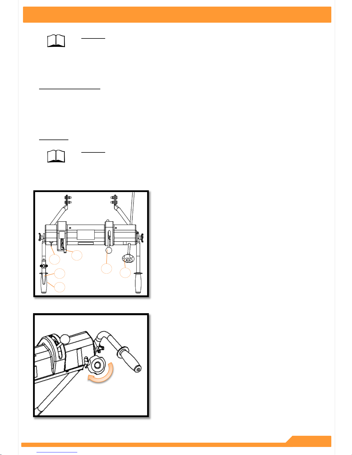
ADJUSTING BELT TENSION
The ground wheel drive belt tension is adjusted by slackening the lock nuts on the cable adjuster, turning and then re-locking
adjuster under guard.
The reel drive belt tension is adjusted by slackening t he lock nut on the barrel of the pull rod. Remove split pin, turn r od to
desired position. Replace split pin and tighten lock nut.
A
B
A = Split Pin
B = Lock Nut
FRONT ROLLER ADJUSTMENT
An adjustment pivot nut is fitted at one side of the front r oller
frame assembly. This has been factory set, during assembly and
should not require further adjustment. However, if the machine
has been dismantled for maintenance purposes or mishandled at
any time, the front roller can be adjusted by placing the machine
on a level surface, with the tine reel removed and rotating the
pivot nut. The front roller is aligned correctly with the rear ground
wheels when all three are resting on the surface.
SP20008_REV3
MAY 2018

9
MAINTENANCE & LUBRICATION
FITTING NEW REEL DRIVE V BELTS
Ensure engine is switched off and key is removed. Remov e covers(2 top and 1 side). Slacken engine bolts and move
engine forward. Undo 2 setscrews securing the brake calliper and lift up and pull
away clear of the disc. Place some packing (cardboard is ideal) in-between the brake pads to keep them in position.
Remove belts on the bearing that is close to the disc and slacken the bolts on the bearing near the large chain pinion.
This allows the shaft to be tilted up and the belt can be removed. Fit a new belt and put shaft back into position.
Replace and tighten the bolts.
Disconnect brake rod from brake lever with the engine turned off. Put the tine reel into drive with the over centre lever.
Ensure that belt fingers on engine are not more than 2mm and not less than 1mm away from the tensioned tine drive
belt. Take the over centre lever out of drive and start engine. Put the ov er centre lever into drive and ensure that the
belts stop driving. When the over centre lever is out of driv e. If the belt stops driv ing, tur n off the engine and refit the
brake rod.
CAUTION
ALWAYS SWITCH OFF THE ENGINE BEFORE ATTEMPTING ANY MACHINE MAINTENANCE WORK.
SP20008_REV3
MAY 2018
 Loading...