

Page 1

Page 2

1
Table of Contents
1. Overview ................................................................................................................................ 2
1.1 Features ...................................................................................................................... 2
1.2 Package Contents ....................................................................................................... 3
1.3 Dimensions .................................................................................................................. 5
1.4 Connectors (Indoor Only)............................................................................................. 6
1.5 Function Cables (Outdoor Only) .................................................................................. 7
2. Camera Cabling ..................................................................................................................... 8
2.1 Power Connection ....................................................................................................... 8
2.2 Ethernet Cable Connection .......................................................................................... 8
2.3 Alarm I/O Connection .................................................................................................. 8
2.4 Waterproof Cable Connector (Outdoor Only) ............................................................... 9
3. System Requirements ........................................................................................................ 11
4. Access Camera ................................................................................................................... 12
5. Setup Video Resolution ...................................................................................................... 18
6. Configuration Files Export / Import ................................................................................... 19
7. Tech Support Information .................................................................................................. 20
7.1 Delete the Existing Viewer ......................................................................................... 20
7.2 Setup Internet Security .............................................................................................. 21
Appendix: Technical Specifications
Page 3

2
1. Overview
The Hyper Mini Dome IP Camera is an easy setup camera with PoE supported
to reduce complicated cabling without sacrificing performance. Quad Streams
Compression (H.264 Baseline / Main / High Profile / SVC + MJPEG) are
supported for efficient bandwidth and storage management. Up to 4K2K real
time resolution is offered for providing high definition images. Also, the H.264
encoder performance can be up to 1080p at 60 fps. For dark environments, the
camera has incorporated WDR, 3DNR and Day/Night ICR technologies to
capture clear images in lowlight conditions.
1.1 Features
Sony Progressive Scan CMOS 3M / 4M / 6M / 8M Sensor
Low Latency Streaming
Low Power Consumption on Encoding
Quad Codec Support-
H.264 Baseline / Main Profile / High Profile / SVC + MJPEG
Quad Streams Support
Smart Event Function-
Motion Detection / Network Failure Detection / Tampering Alarm / Periodical
Event / Manual Trigger Event / Audio Detection
Text Overlay and Privacy Masks
3D Motion Compensated Noise Reduction (MCTF)
True Day / Night Function (ICR)
IR LED Module support (working distance up to 40m)*
Weatherproof (IP66 International)*
64GB micro SD Card support
ONVIF Profile S Support
(*) Optional
Page 4
3
1.2 Package Contents
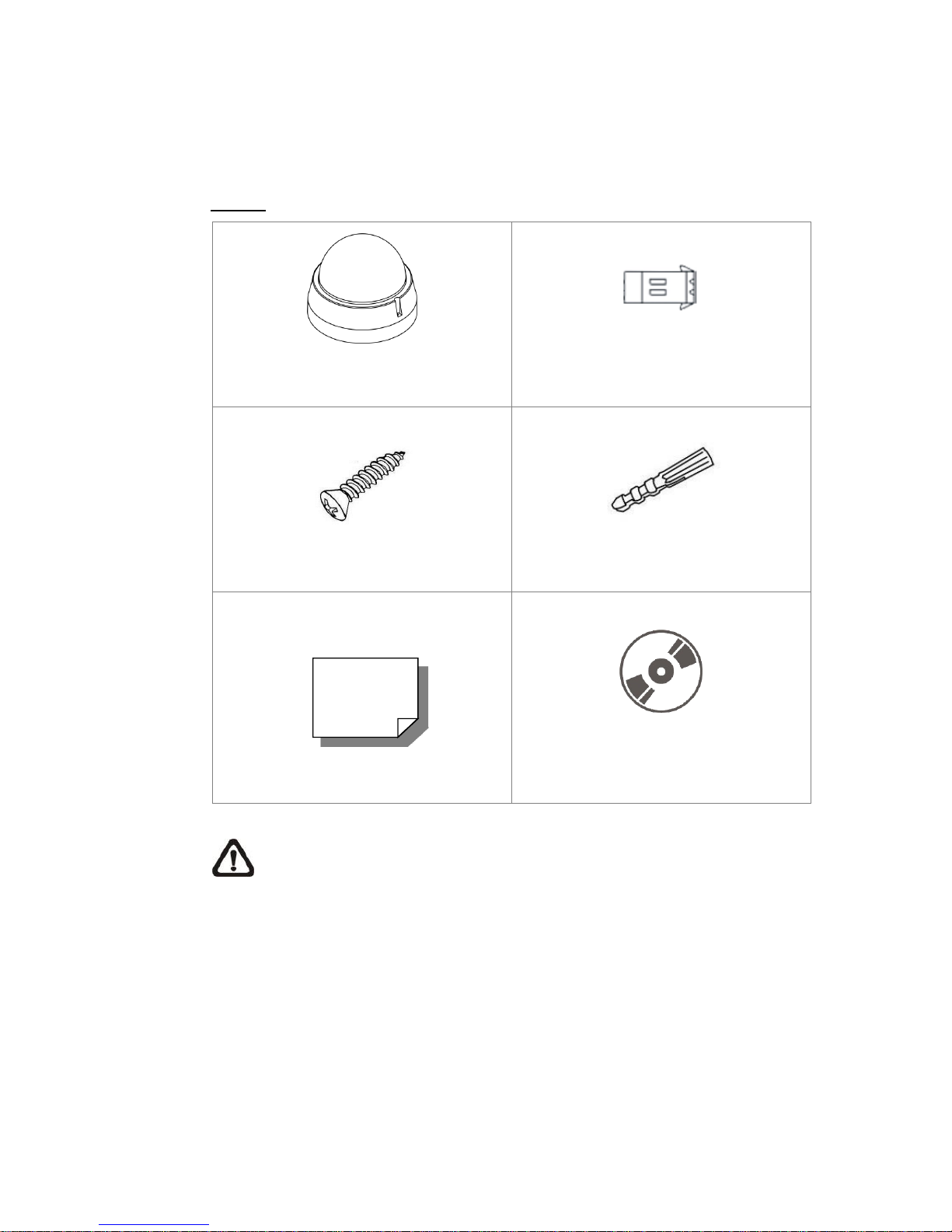
Please check the package containing the following items listed below.
Indoor
Hyper Mini Dome IP Camera
2-Pin Power Terminal Block
Self-Tapping Screw (x3)
Plastic Screw Anchor (x3)
Quick Guide
CD
(bundled software and documentation)
NOTE: The supplied self-tapping screws are for soft substances /
materials such as wood. For other installation environments such as
cement wall, it is required to pre-drill and use plastic anchors before
fastening the supplied self-tapping screws on the wall.
Page 5
4
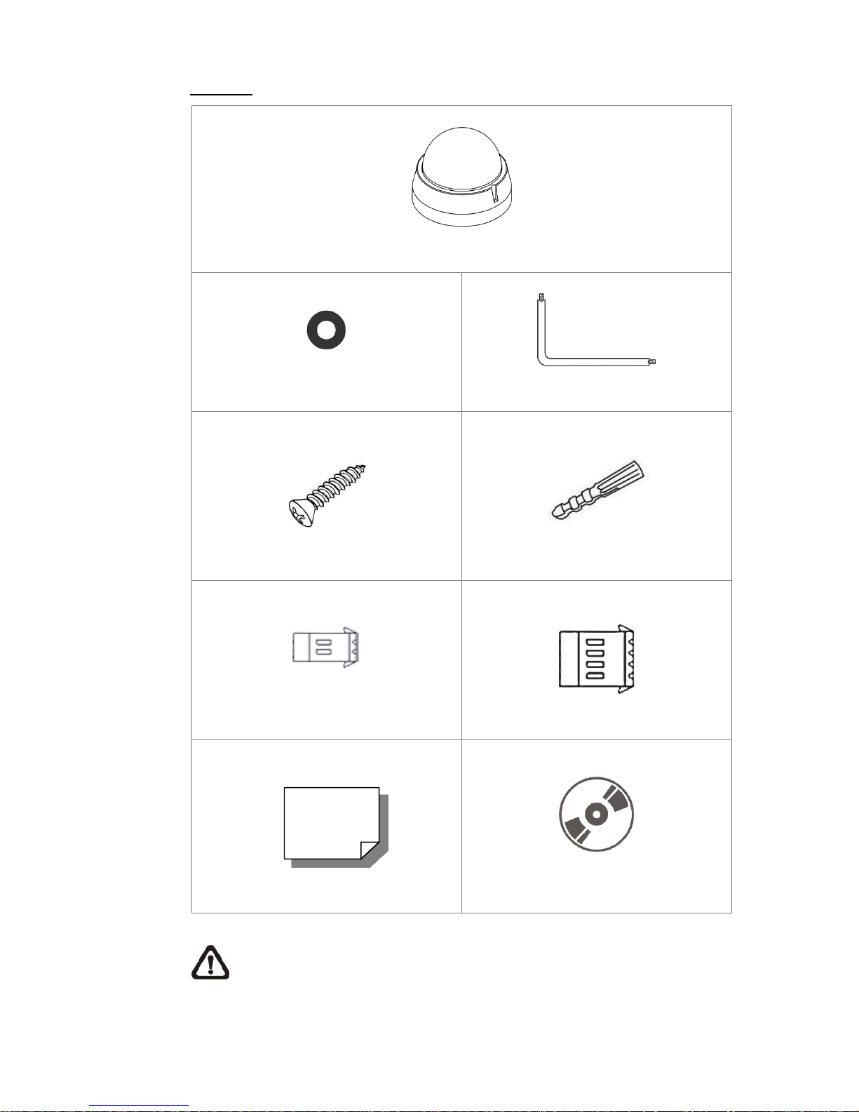
Outdoor
Hyper Mini Dome IP Camera
Rubber Washer (x2)
Security Torx
Self-Tapping Screw (x3)
Plastic Screw Anchor (x3)
2-Pin Power Terminal Block
4-Pin Alarm I/O Terminal Block
Quick Guide
CD
(bundled software and documentation)
NOTE: The supplied self-tapping screws are for soft substances /
materials such as wood. For other installation environments such as
cement wall, it is required to pre-drill and use plastic anchors before
fastening the supplied self-tapping screws on the wall.
Page 6
5
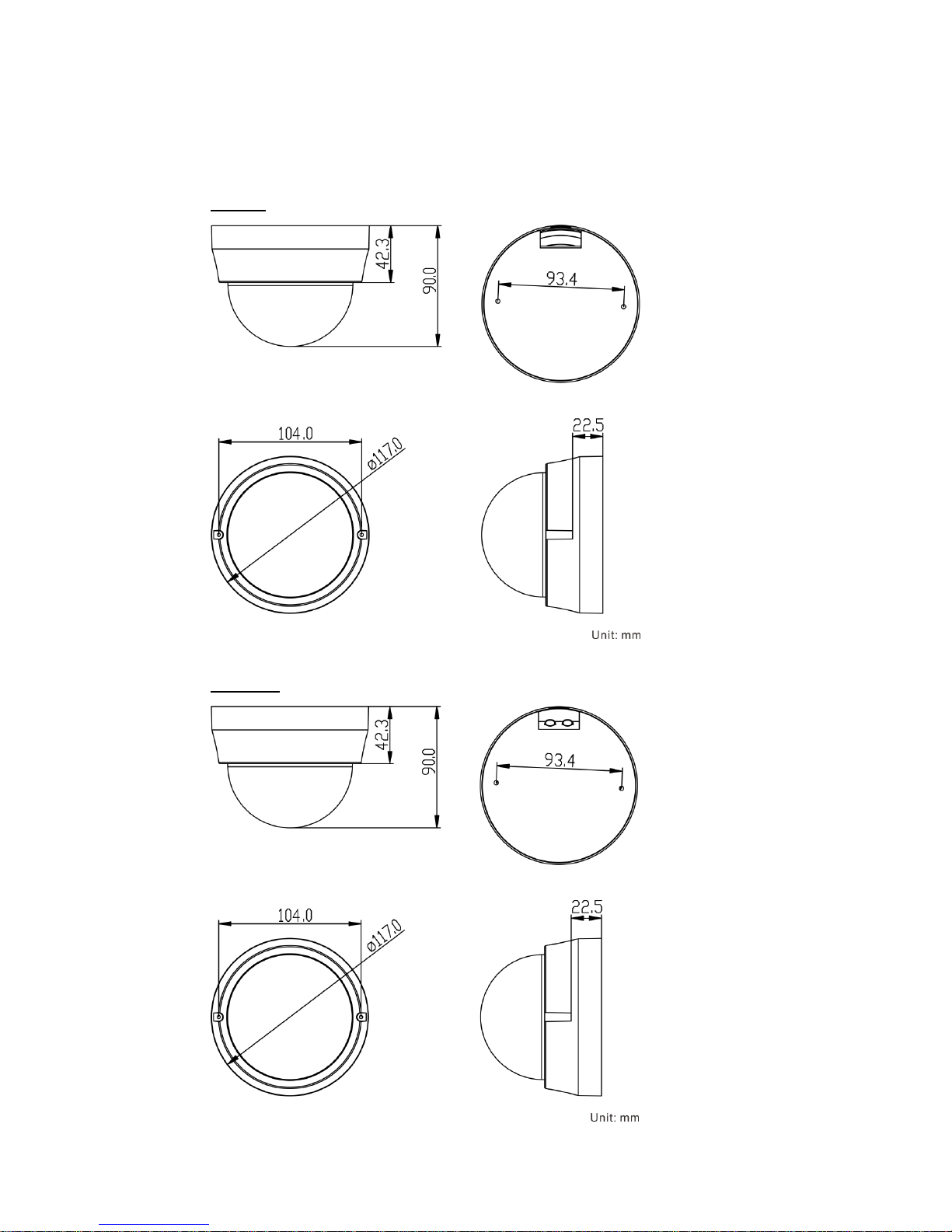
1.3 Dimensions
The dimensions of the camera are shown below.
Indoor
Outdoor
Page 7
6
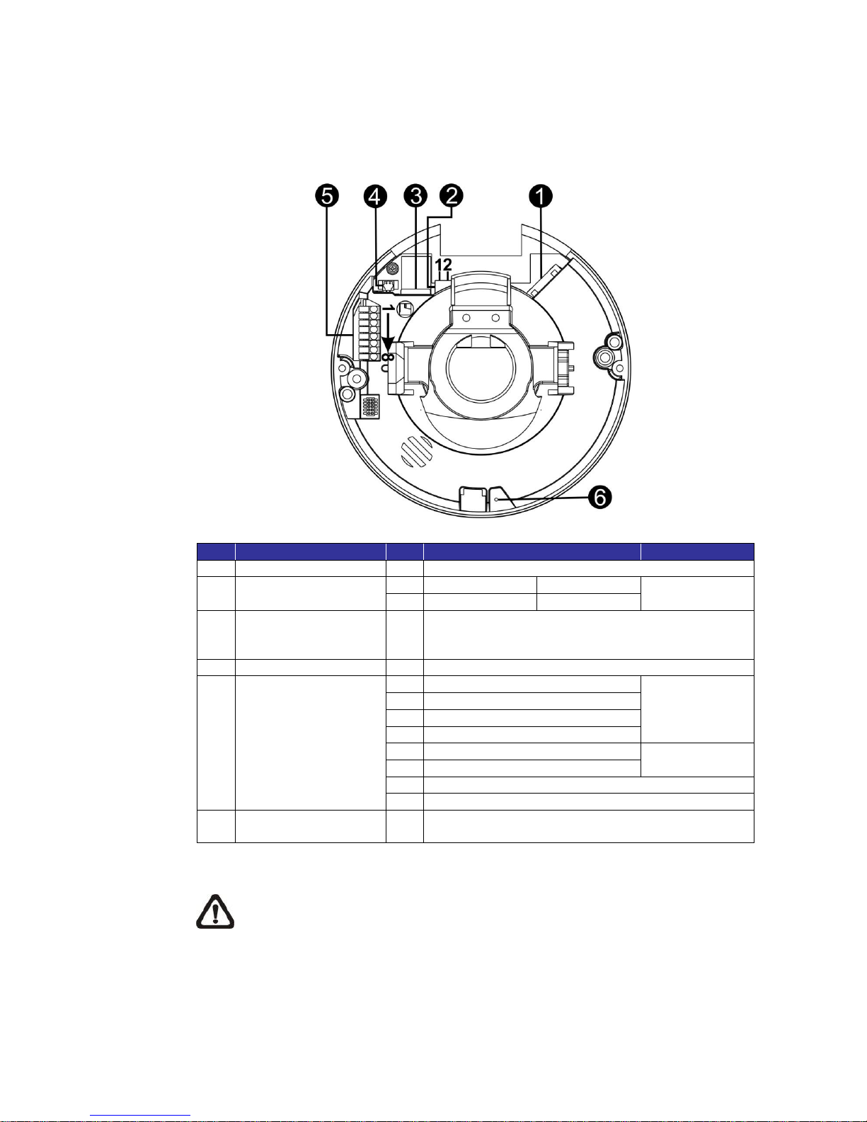
1.4 Connectors (Indoor Only)
The diagram below shows the default button and various connectors of the
camera. Definition for each connector is given as follows.
No.
Connector
Pin
Definition
Remarks
1
RJ-45
-
For network and PoE connections
2
Power
(DC 12V / AC 24V)
1
AC 24V 1
DC 12V
Power
connection
2
AC 24V 2
GND
3
microSD Card Slot
-
Insert the microSD card into the card slot to store
videos and snapshots. Do not remove the microSD
card when the camera is powered on.
4
BNC*
-
For analog video output
5
Alarm & Audio I/O
1
Alarm In –
Alarm
connection
2
Alarm In +
3
Alarm Out –
4
Alarm Out +
5
Audio Out R
Audio Out
6
Audio Out L
7
GND
8
Audio In
6
Default Button
-
Press the button with a proper tool for at least 20
seconds to restore the system.
(*) Optional. Please contact the manufacturer for the compatible BNC cable.
NOTE: It is not recommended to record with the microSD card for 24/7
continuously, as it may not be able to support long term continuous data
read/write. Please contact the manufacturer of the microSD card for
information regarding reliability and life expectancy.
Page 8
7
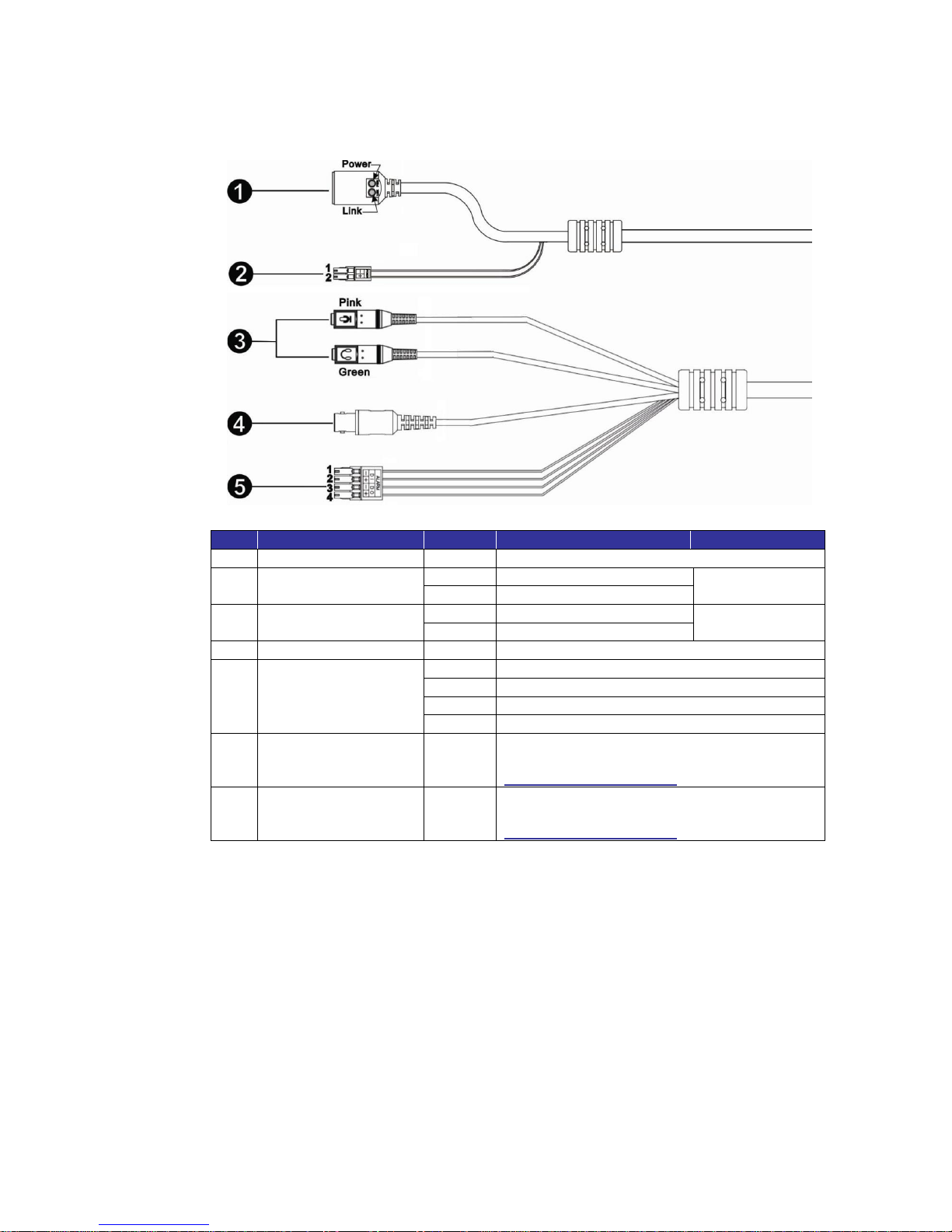
1.5 Function Cables (Outdoor Only)
No.
Connector
Pin
Definition
Remarks
1
RJ-45
-
For network and PoE connection
2
Power*
(DC 12V / AC 24V)
1
DC 12V 1 / AC 24V 1
Power
connection
2
DC 12V 2 / AC 24V 2
3
Audio I/O*
Pink
Audio In
Two-way audio
transmission
Green
Audio Out
4
BNC*
-
For analog video output
5
Alarm I/O*
1
Alarm In –
2
Alarm In +
3
Alarm Out –
4
Alarm Out +
-
Default Button
-
For the position of the default button, please
refer to the diagram shown in section
Connectors (Indoor Only).
-
microSD Card Slot
-
For the position of the microSD card slot,
please refer to the diagram shown in section
Connectors (Indoor Only).
(*) Optional
Page 9
8
2. Camera Cabling
Before users connect cables, make sure that all cables and the power adaptor
are placed in dry and well-waterproofed environments, e.g. waterproof boxes.
The purpose is to prevent moisture accumulation inside the camera and
moisture penetration into cables, which might lead to camera breakdown.
Please refer to the following sections for camera connection.
2.1 Power Connection
For power connection, please refer to section Connectors (Indoor Only) for
indoor models, and see section Function Cables (Outdoor Only) for outdoor
models. Alternatively, users can power the camera by PoE if a Power Sourcing
Equipment (PSE) switch is available. Please refer to the section below for
Ethernet cable connection.
NOTE: If PoE is used, make sure PSE is in use in the network.
2.2 Ethernet Cable Connection
For best transmission quality, cable length shall not exceed 100 meters.
Connect one end of the Ethernet cable to the RJ-45 connector of the camera /
function cable, and plug the other end of the cable to the network switch or PC.
NOTE: In some cases, Ethernet crossover cable might be needed when
connecting the IP camera directly to the PC.
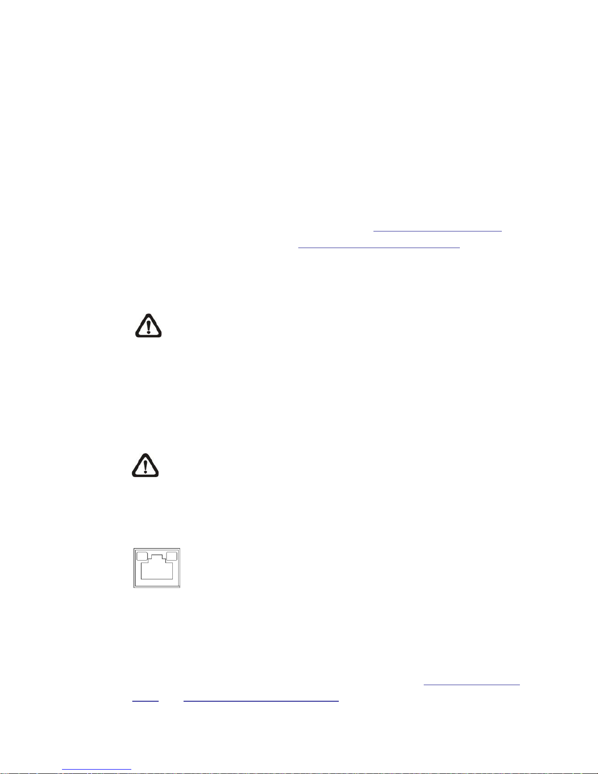
Check the status of the link indicator and the activity indicator LEDs. If the LEDs
are unlit, please check the LAN connection.
Green Link Light indicates good network connection.
Orange Activity Light flashes for network activity indication.
2.3 Alarm I/O Connection
For indoor models, connect alarm devices to the first 4 pins of the camera’s
8-pin terminal block. For outdoor models, connect alarm devices to the 4-pin
terminal block of the All-in-One cable. Refer to sections Connectors (Indoor
Only) and Function Cables (Outdoor Only) for the pin definitions.
Page 10
9
2.4 Waterproof Cable Connector (Outdoor Only)
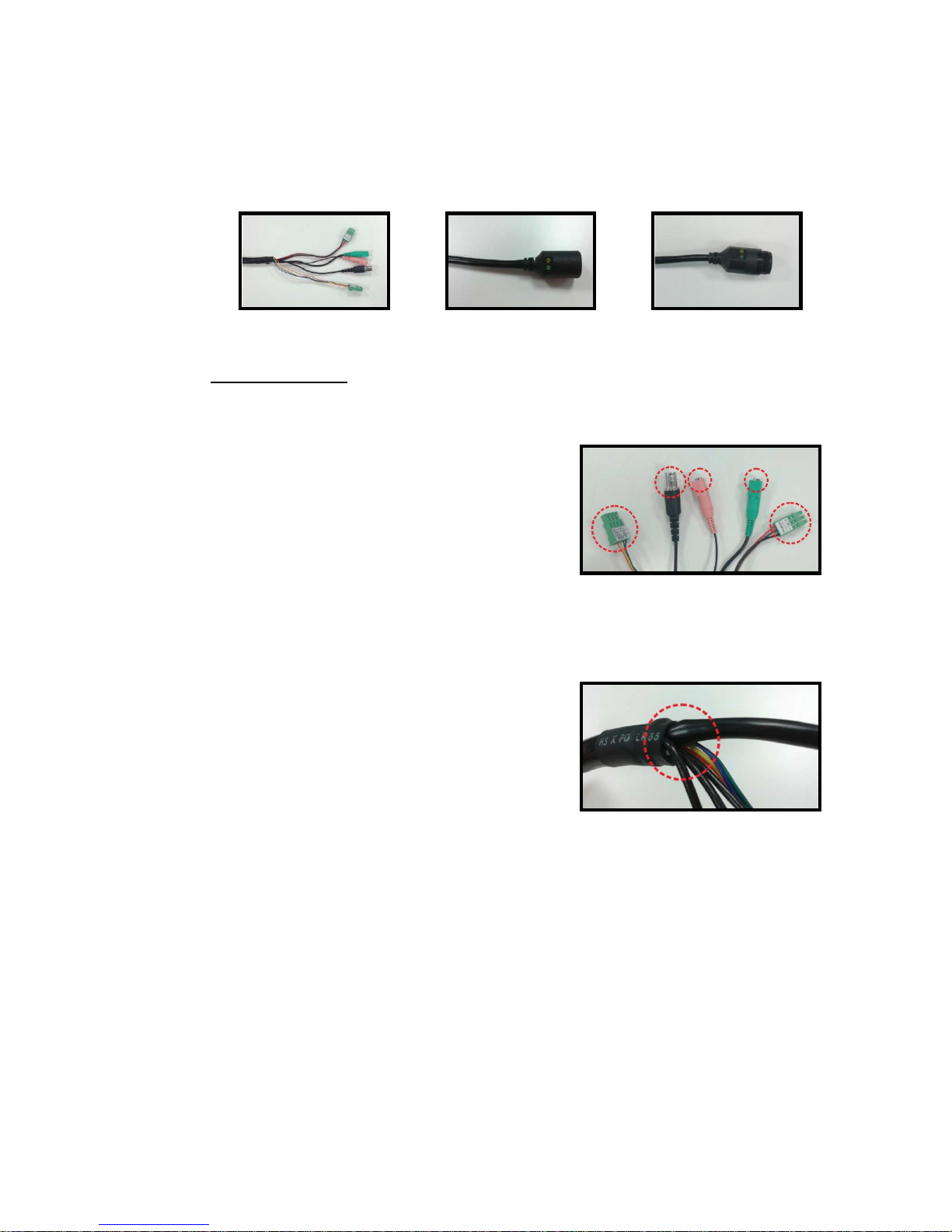
Follow the instruction below to waterproof the connectors of different types of
cables. The supported cables are as shown below.
All-in-One Cable
RJ-45 Cable
IP66 RJ-45 Cable
All-in-One Cable
Follow the steps below to waterproof the connectors of the All-in-One cable.
Step 1:
Plug the cables to the connectors of the
All-in-One cable and coat the joints with
silicone gel. There should be no gap between
the connectors and the cables. For alarm I/O
connector and power connector, make sure
the side with wires attached is also sealed
with silicone gel.
Step 2:
Seal the end of the rubber coating of the
All-in-One cable as indicated in the figure on
the right. Please use enough silicone gel to
fill in the hose and wrap around each wire;
otherwise, waterproof function cannot be
guaranteed.
Page 11
10
RJ-45 Cable
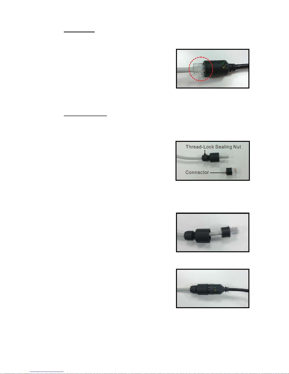
Follow the instruction below to waterproof the connector of the RJ-45 cable.
Plug the Ethernet cable to the connector of
the RJ-45 cable and coat the joint with
silicone gel. Make sure there is no gap
between the Ethernet cable and the
connector; otherwise, waterproof function
cannot be guaranteed.
IP66 RJ-45 Cable
For IP66 RJ-45 cable, please use an RJ-45 IP66 plug for connection to prevent
water damage. Follow the steps below for cable connection.
Step 1:
Take out the supplied connector from the
RJ-45 IP66 plug. Loosen the thread-lock
sealing nut on the plug. Then thread the
Ethernet cable through the thread-lock
sealing nut and the plug. If the Ethernet cable
is already attached to a connector, please
remove it first.
Step 2:
Carefully remove a section of rubber coating
from the end of the Ethernet cable to reveal
the wires. Inset the wires to the correct pins
of the connector. Plug the Ethernet cable to
the connector of IP66 RJ-45 cable.
Step 3:
Fasten the RJ-45 IP66 plug to the connector
of the IP66 RJ-45 cable. Lastly, tighten the
thread-lock sealing nut to the plug.
Page 12

11
3. System Requirements
To perform the IP camera via web browser, please ensure the PC is in good
network connection, and meet system requirements as described below.
Items
System Requirement
Personal Computer
Minimum :
1. Intel® Core
TM
i5-2430M @ 2.4 GHz
2. 4 GB RAM
Recommended :
1. Intel® Core
TM
i7-870 @ 2.93 GHz
2. 8 GB RAM
Operating System
Windows VISTA / Windows XP / Windows 7
Web Browser
Microsoft Internet Explorer (recommended)
Firefox
Chrome
Safari
Network Card
10Base-T (10 Mbps), 100Base-TX (100 Mbps) or
1000Base-T (1000 Mbps) operation
Viewer
ActiveX control plug-in for Microsoft IE
Page 13

12
4. Access Camera
For initial access to the IP camera, users can search the camera through the
installer program: DeviceSearch.exe, which can be found in “DeviceSearch”
folder in the supplied CD.
Accessing the Camera by Device Search Software
Step 1: Double click on the program Device Search.exe.
Step 2: After its window appears, click on the <Device Search> button on the
top. All the finding IP devices will be listed in the page.
Step 3: Find the camera in the list by its IP address and click on it. The default
IP address of the camera is: 192.168.0.250.
Step 4: The default IP address of the camera may not be in the same LAN as
the IP address of the PC. If so, the IP address of the camera needs to
be changed. Right click on the camera and click <Network Setup>.
Meanwhile, record the MAC address of the camera, for future
identification.
Step 5: The <Network Setup> page will come out. Select <DHCP> and click
<Apply> down the page. The camera will be assigned with a new IP
address.
Step 6: Click <OK> on the Note of setting change. Wait for one minute to
re-search the camera.
Step 7: Click on the <Device Search> button to re-search all the devices. Find
the camera in the list by its MAC address. Then double click or right
click and select <Browse> to access the camera directly via a web
browser.
Page 14
13
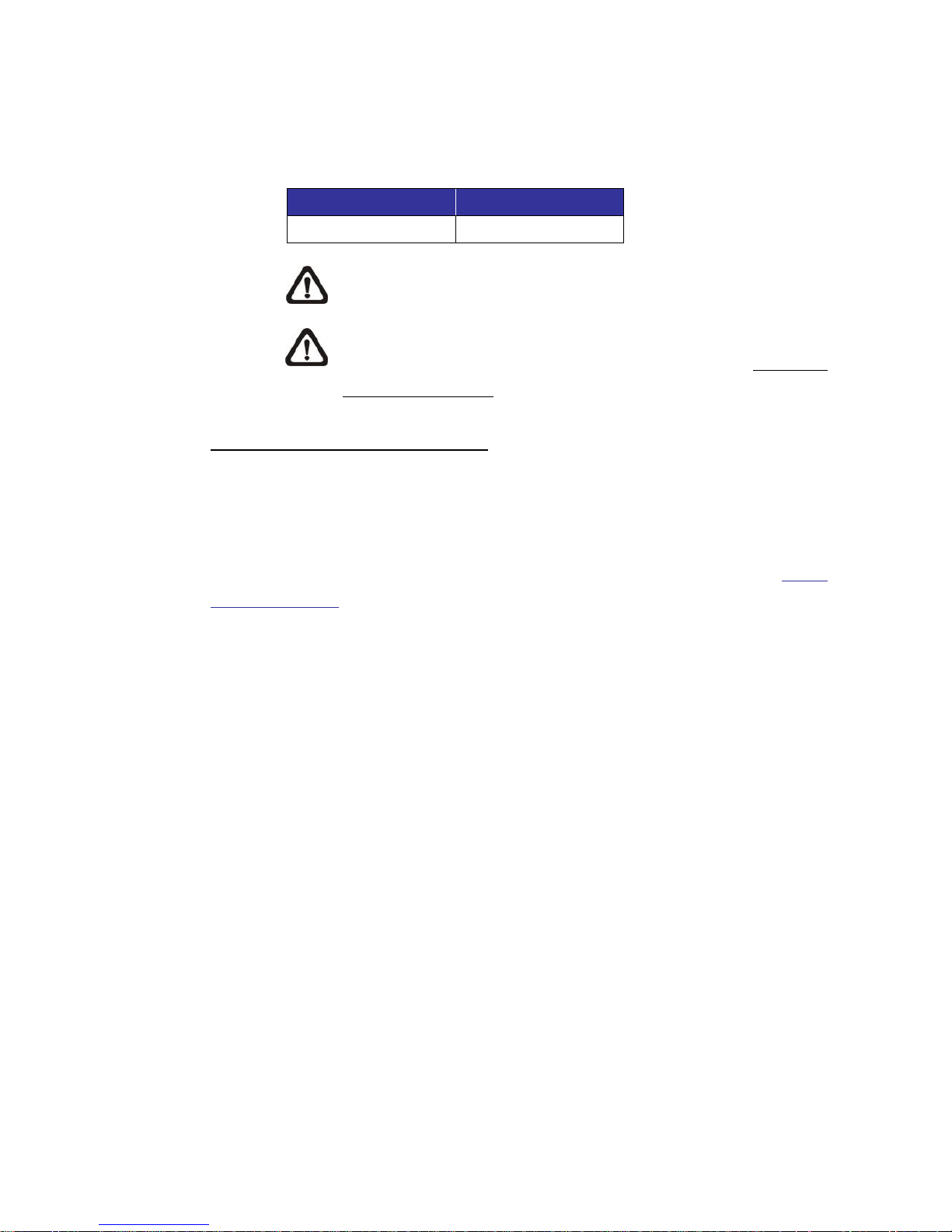
Step 8: A prompt window requesting for default username and password will
appear. Enter the default username and password shown below to
login to the camera.
Login ID
Password
Admin
1234
NOTE: ID and password are case sensitive.
NOTE: It is strongly advised that administrator’s password be
altered for the security concerns. Refer to the Hyper IP
Camera Menu Tree in the supplied CD for further details.
Installing Viewer Software Online
For the initial access to the IP camera, a client program, Viewer, will be
automatically installed to the PC when connecting to the camera.
If the web browser doesn’t allow Viewer installation, please check the Internet
security settings or ActiveX controls and plug-ins settings (refer to section Setup
Internet Security) to continue the process.
The Information Bar (just below the URL bar) may come out and ask for
permission to install the ActiveX Control for displaying video in browser.
Right click on the Information Bar and select <Install ActiveX Control…> to allow
the installation.
The download procedure of Viewer software is specified as follows.
Step 1: In the Viewer installation window, click on <Next> to start the
installation.
Step 2: The status bar will show the installation progress. After the installation
is completed, click on <Finish> to exit the installation process.
Step 3: Click on <Finish> to close the Viewer installation page.
Page 15
14
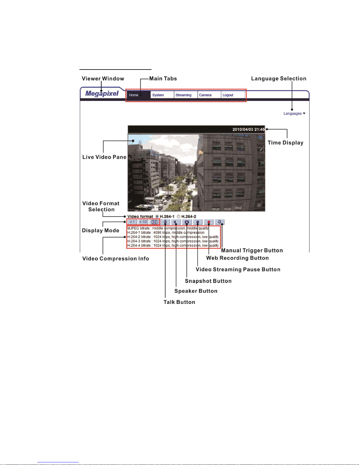
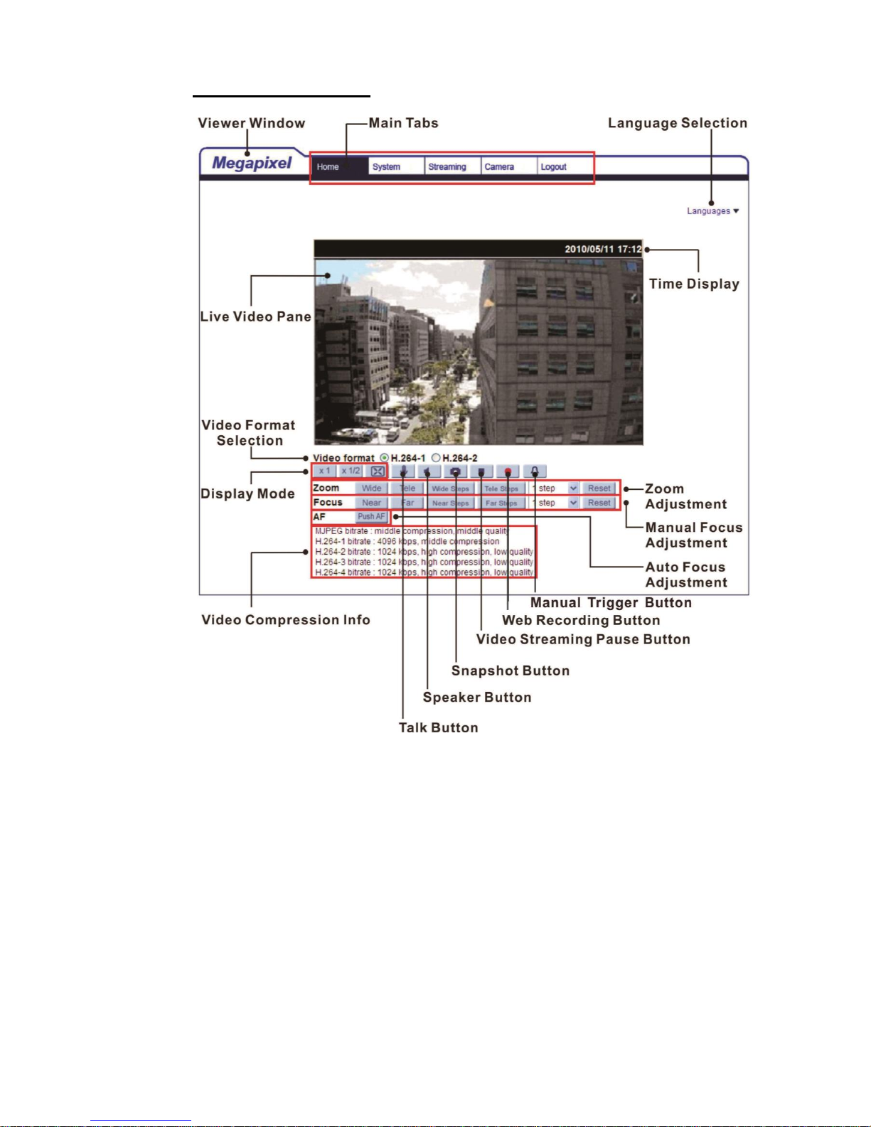
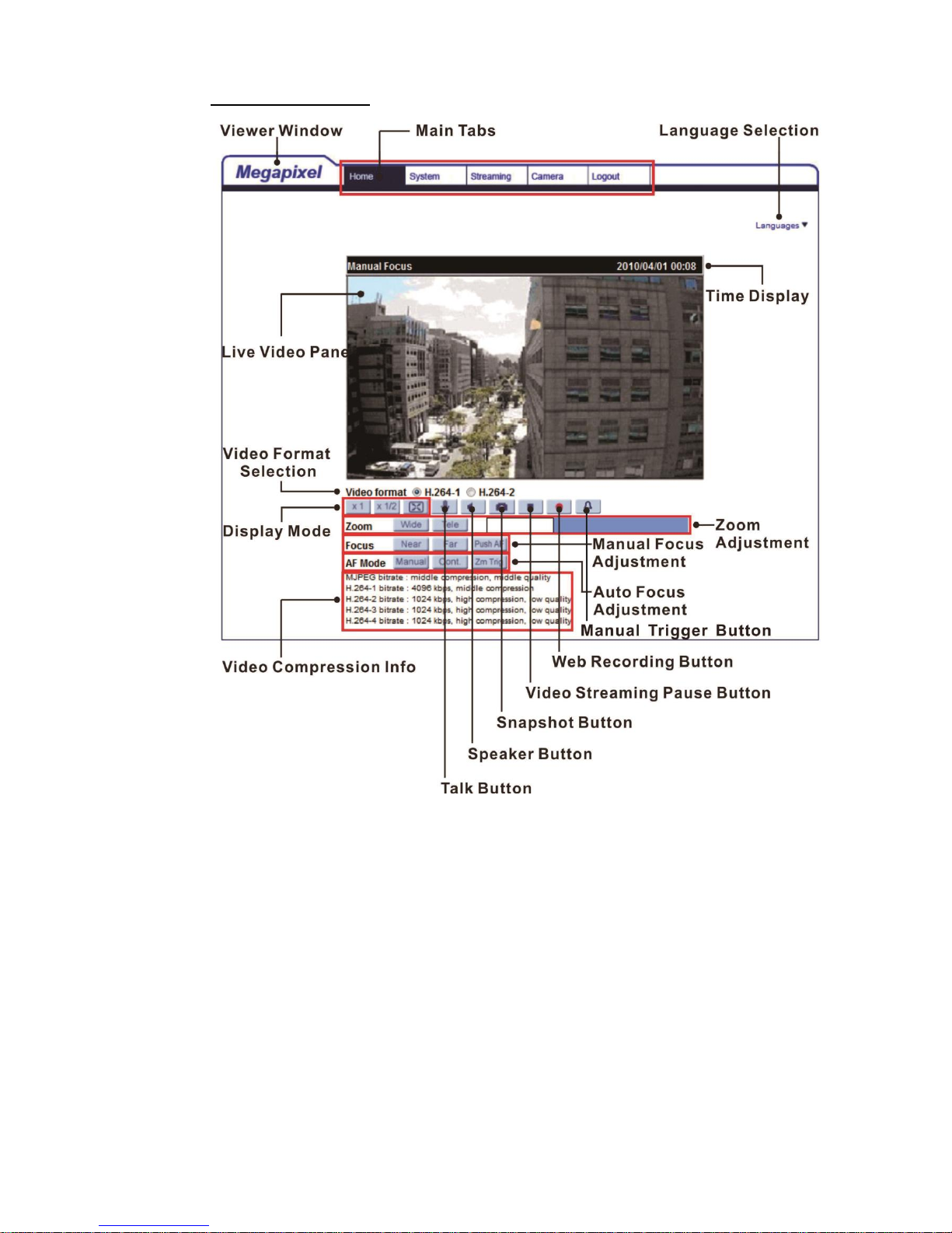
Once the Viewer is successfully installed, the Home page of the IP camera will
be shown as the figure below.
Vari-focal Lens Models
Page 16
15
Motorized Lens Models
Page 17
16
3x AF Lens Models
Page 18
17
Zoom and Focus Adjustment (Vari-focal Lens Models)
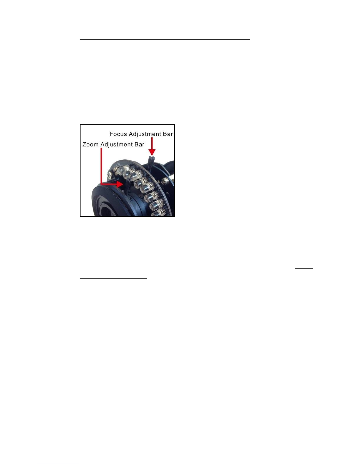
For vari-focal lens models, zoom and focus can be adjusted by the adjustment
bars on the camera lens inside the dome cover. To adjust zoom and focus,
please detach the dome cover first. For indoor models, use a plus screw driver
to loosen the two screws of the camera. For outdoor models, use the supplied
security torx to loosen the two security screws of the camera. Detach the dome
cover. Then use the zoom adjustment bar and the focus adjustment bar
(positions shown in the following figure) to adjust zoom and focus.
Zoom and Focus Adjustment (Motorized Lens / 3x AF Lens Models)
The live image will be displayed on the Home page when the camera is
successfully accessed. If zoom or focus is not at the desired position, please
use the function buttons on the Home page for adjustment. Refer to the Hyper
IP Camera Menu Tree in the supplied CD for more details about the function
buttons.
Page 19
18
5. Setup Video Resolution
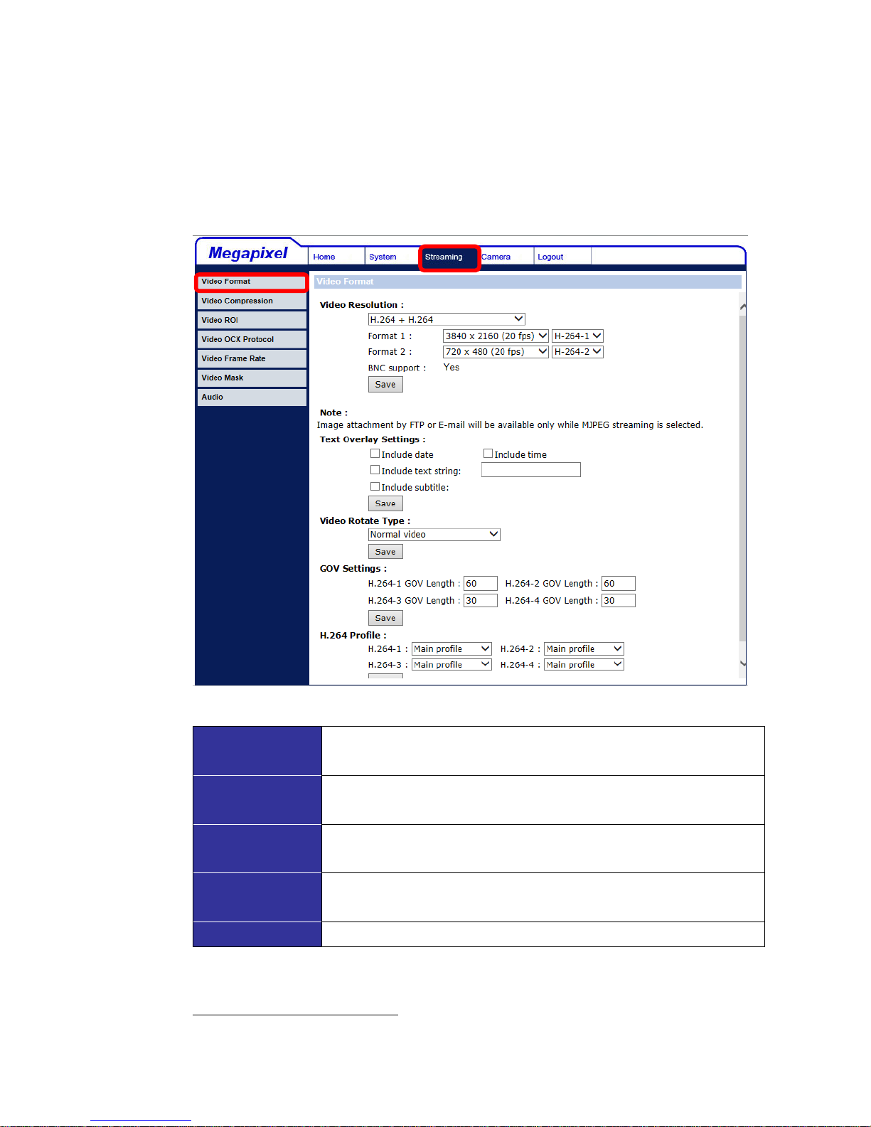
Users can setup video resolution on the Video Format page of the user-friendly
browser-based configuration interface.
Video Format can be found under this path: Streaming> Video Format.
The default values of the video resolution are as below.
3M
H.264- 2048 x 1536 (25/30 fps) +
H.264- 720 x 576 (25 fps) / 720 x 480 (30 fps)
3M- Advanced
H.264- 2048 x 1536 (50/60 fps) +
H.264- 720 x 576 (50 fps) / 720 x 480 (60 fps)
4M- Advanced
H.264- 2560 x 1440 (25/30 fps) +
H.264- 720 x 576 (25 fps) / 720 x 480 (30 fps)
6M- Advanced
H.264- 3072 x 2048 (25/30 fps) +
H.264- 720 x 576 (25 fps) / 720 x 480 (30 fps)
8M- Advanced
H.264- 3840 x 2160 (20 fps) + H.264- 720 x 480 (20 fps)
For more details about combinations of video resolution, please refer to the
Hyper IP Camera Menu Tree in the supplied CD.
Page 20

19
6. Configuration Files Export / Import
To export / import configuration files, users can access the Maintenance page
on the user-friendly browser-based configuration interface.
The Maintenance setting can be found under this path: System> Maintenance.
Users can export configuration files to a specified location and retrieve data by
uploading an existing configuration file to the camera. This is especially
convenient to make multiple cameras having the same configuration.
Export
Users can save the system settings by exporting the configuration file (.bin) to a
specified location for future use. Click on the <Export> button, and the popup
File Download window will come out. Click on <Save> and specify a desired
location for saving the configuration file.
Upload
To upload a configuration file to the camera, click on <Browse> to select the
configuration file, and then click on the <Upload> button for uploading.
.
Page 21

20
7. Tech Support Information
This chapter will introduce how to delete previously-installed Viewer in the PC
and how to setup the Internet security.
7.1 Delete the Existing Viewer
For users who have installed the Viewer in the PC previously, please remove
the existing Viewer from the PC before accessing to the IP camera.
Deleting the Viewer
In the Windows <Start Menu>, activate <Control Panel>, and then double click
on <Add or Remove Programs>. In the <Currently installed programs> list,
select <Viewer> and click on the button <Remove> to uninstall the existing
Viewer.
Deleting Temporary Internet Files
To improve browser performance, it is suggested to clean up all the files in the
Temporary Internet Files. The procedure is as follows.
Step 1: In the web browser, clicks on the <Tools> tab on the menu bar and
select <Internet Options>.
Step 2: Click on the <Delete> button under <Browsing history> section. In the
appeared window tick the box beside the <Temporary Internet files>.
Step 3: Click on <Delete> to start deleting the files.
Page 22

21
7.2 Setup Internet Security
If ActiveX control installation is blocked, please either set Internet security level
to default or change ActiveX controls and plug-ins settings.
Internet Security Level: Default
Step 1: Start the Internet Explorer (IE).
Step 2: Click on the <Tools> tab on the menu bar and select <Internet
Options>.
Step 3: Click on the <Security> tab, and select <Internet> zone.
Step 4: Down the page, click on the <Default Level> button and click on <OK>
to confirm the setting. Close the browser window, and restart a new one
later to access the camera.
ActiveX Controls and Plug-ins Settings
Step 1: Repeat Step 1 to Step 3 of the previous section above.
Step 2: Down the page, click on the <Custom Level> button to change ActiveX
controls and plug-ins settings. The Security Settings window will pop
up.
Step 3: Under <ActiveX controls and plug-ins>, set ALL items (as listed below)
to <Enable> or <Prompt>. Please note that the items vary by IE
version.
ActiveX controls and plug-ins settings:
1. Binary and script behaviors.
2. Download signed ActiveX controls.
3. Download unsigned ActiveX controls.
4. Allow previously unused ActiveX controls to run without prompt.
5. Allow Scriptlets.
6. Automatic prompting for ActiveX controls.
7. Initialize and script ActiveX controls not marked as safe for scripting.
8. Run ActiveX controls and plug-ins.
9. Only allow approved domains to use ActiveX without prompt.
10. Script ActiveX controls marked safe for scripting*.
11. Display video and animation on a webpage that does not use external media player.
Step 4: Click on <OK> to accept the settings. A prompt window will appear for
confirming the setting changes, click <Yes(Y)> to close the Security
Setting window.
Step 5: Click on <OK> to close the Internet Options screen.
Step 6: Close the browser window, and restart a new one later to access the IP
camera.
 Loading...