

Page 1
SPECIFICATIONS
No.
1
2
3
4
5
6
7
8
9
10
11
12
13
Parameter
Model No:
Voltage Requirement
Power Consumption
Video
Connection method
Monitor screen
Call tone
Communication
Communication
Duration
Communication
Distance
Operating
Temperature
Weight
Dimensions (mm)
Description
S35B_M
100V-240V, 50 Hz / 60Hz
Standby: 1W; Operation:<5W
1Vp-p 75Ω,PAL or NTSC
Four wire;
3.5 Digital TFT LCD "
all from camera: Electronic chime
Simultaneous type
60 sec±10%
AWG #22-26, 50-100 meter
0℃ +40℃(32°F~104 F)~ °
Net :700g Gross:1000g
192*195*38.5mm
www. sisca m.com .ve
Video Door Phone Monitor,
Villa/Building System(s)
Model Number: S35B_M
11
IM PO RTANT CA UT IONS----- -- ----------- -- ----------- -- --1
PA RT S CH EC KL IS T
FE AT UR ES
IN ST AL LA TI ON
WI RI NG
OP ER AT IO N -
SP EC IF IC AT IO NS
-- --- ----- --- -- --- ----- --- ----- --- -- --- ----- --2
-- -- ---------------------------------------------3
----- --- --- --- --- --- --- --- --- --- --- --- -1
-- --- --- --- --- --- ----- --- --- --- --- ----- --- 2
-- -- ----------------------------------------4
-- -- ----------- -- -- ------------- -- ------11
Page 2
IMPORTANT CAUTIONS
1. To prevent fire or shock hazard, do not expose the unit to rain,
moisture or other liquid and do not overload the power cord.
2. Instructions! Read and keep the instructions-all safety and
operating instructions should be read and followed before the unit is
operated .
3. Power Sources! This equipment should be operated only from the
Storage Selection
In this menu, you can select between IM (internal memory) and SD card.
Sys tem Set ting
Gen eral Se tting
Def ault Se tting R estor e
Sto rage Se lecti on
Dis k Info
For mat
Abo ut
>
>
>
>
>
>
Sto rage Se lecti on
Inn er Memo ry
SD CA RD
type of power source indicated on the marking label and the power
cord protection is needed.
4. Servicing and replacement of parts! Do not attempt to service this
product or replace any part inside by yourself as opening or removing
covers may expose you to dangerous voltage or other hazards. Refer
all servicing to qualified service personnel.
5 . Lightning! For added protection for this product before a
lightning storm, or when it is left unattached and unused for long
periods of time, unplug it from the wall outlet and disconnect the cable
system. This will prevent damage to the product due to lightning and
power-line, telephone-line, RF cable and Actuator/Polarization surge
protectors to protect your system from possible damage.
6. Move with care! This product is easy for damage, care for it during
transportation, storage and installation.
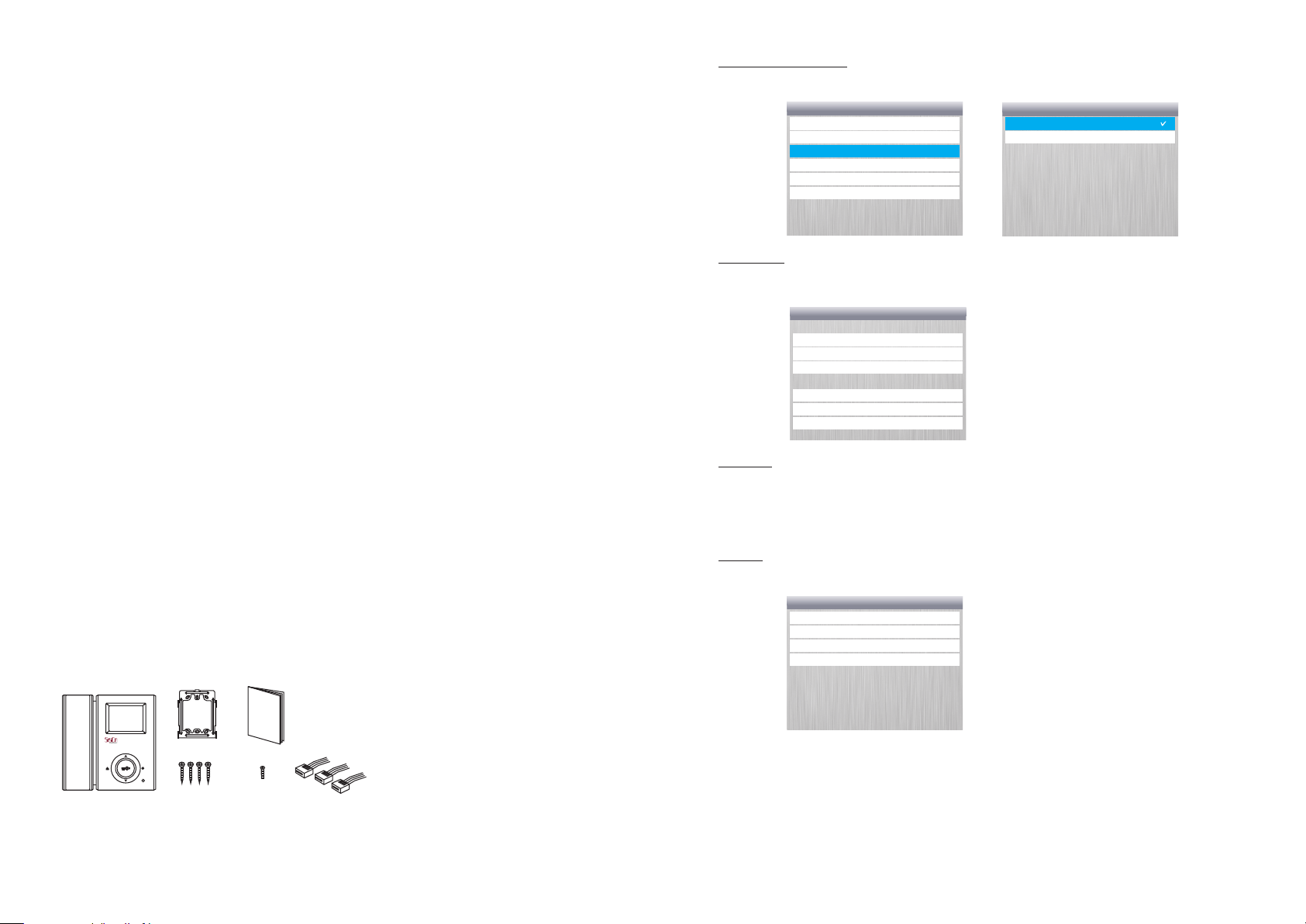
PARTS CHECKLIST
²Monitor unit 1
m
a
n
Mon itor
Wall m ounti ng Brac ket
T4X 18
Scre w for wal l mount
u
a
l
Man ual
M3X 6
Moni tor Fix S crew
4P Con necto r
²User manual 1
² Mounting bracket 1
²Connector cable 3
²Accessory Bag 1
(screw 4x18mm x 4, screw
anchor x4, M3x6 x1)
Disc Info
In this menu, you can see the current available memory capacity.
Dis k Info
Inn er Memo ry
Cap abili ty:
Use d:
Ava ilabl e:
SD CA RD
Cap abili ty:
Use d:
Ava ilabl e:
425 .695M B
306 .0KB
425 .396M B
0 byt es
0 byt es
0 byt es
>
>
>
>
>
>
Format
This entry is to provide an option for whether you want to format the
IM and SD card. If you choose "Format", all the saved recording files
will be deleted.
About
In this menu, you can see the listed information for this device.
Abo ut
Com pany:
Pro duct:
SW Ve rsion : ver 1.2 1
HW Ve rsion : ver 1.2 3
1
10
Page 3
In "Minimum Alarm Space", you can choose a space from:
Gen eral Se tting s
Lan guage
Aut o Recov er
Dat e Setti ng
Tim e Setti ng
Dat e/Tim e Forma t Setti ng
Min imum Al arm Spa ce
Pow er Off Ti mer
Dis play Se tting
>
>
>
>
>
>
>
>
Min imum Al arm Spa ce
10 MB
20 MB
30 MB
50 MB
80 MB
In "Power off Timer", you can choose a time from:
Gen eral Se tting s
Lan guage
Aut o Recov er
Dat e Setti ng
Tim e Setti ng
Dat e/Tim e Forma t Setti ng
Min imum Al arm Spa ce
Pow er Off Ti mer
Dis play Se tting
>
>
>
>
>
>
>
>
Pow er Off Ti mer
Off
1 Min ute
5 Min utes
10 Mi nutes
In "Display Setting", There are three entrances: Brightness Option,
Contrast Option, Color Option. You can press "UP" and "DOWN" to
choose an entrance.
Gen eral Se tting s
Lan guage
Aut o Recov er
Dat e Setti ng
Tim e Setti ng
Dat e/Tim e Forma t Setti ng
Min imum Al arm Spa ce
Pow er Off Ti mer
Dis play Se tting
>
>
>
>
>
>
>
>
Dis play Se tting
Bri ghtne ss 08
Con trast 0 8
Col or 08
FEATURES
²3.5" digital color TFT LCD display ;
²Handset voice talk, four wire connection;
²Intercom Audio handset extendable;
²Applicable for both villa and multi apartment system;
²Two camera connection and with internal auto switch;
²Audio/Video recording and play back .
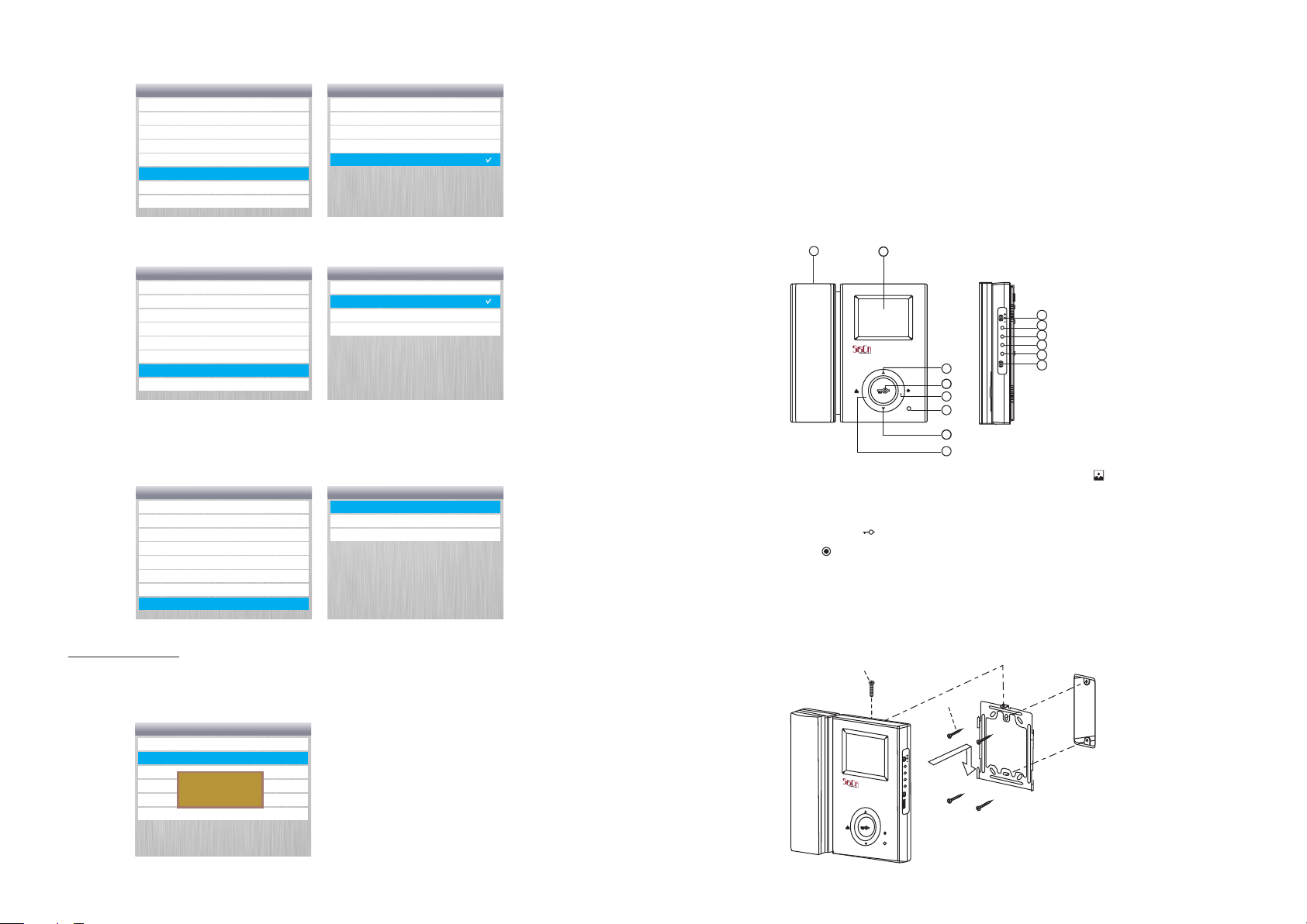
1
1. Handset;
2. Monitor Screen : 3.5” TFT LC D 9
3. Up Key ( ▲ );
4. Lock Release Button ( ) ; 11
5. Intercom Key ( ) ; .Contrast Key;
6.Power Indicator; 13.R eset;
7.Down Key( ▼ ) ; 14.Power Switc h;
2
9
10
BRIGHT
11
COLOR
12
CONT
13
RESET
ON
14
3
4
5
6
787
OFF
8. Monitor Key ( );
. Audio Volume;
10. Brightness Key;
.Color Key;
12
Default Setting
In "Default Setting" you can choose whether restore the default
ex_factory settings.
Sys tem Set ting
Gen eral Se tting
Def ault Se tting R estor e
Sto rage Se lecti on
Sett ings w ill be
Dis k Info
chan ged. R estor e
the DE FAUL T setti ngs?
For mat
Abo ut
>
>
>
>
>
>
9
INSTALLATION
SCRE W M3(1EA)
BRIGHT
OR
COL
T
CON
RESET
ON
OFF
SCRE W T4(4EA)
2
Page 4
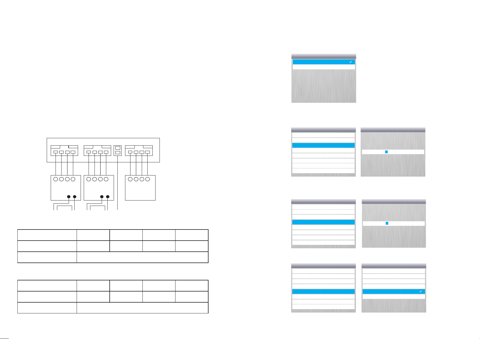
1. Select monitor mounting location, fix the mounting bracket
securely to the wall with the screw and anchors provided.
2. Drill a hole in the center area of the bracket just large enough to
pull through the wiring cables.
3 . Connect the cable(s) from the camera unit(s).
4. Connect the handset cord to the monitor.
5. Attach the wired monitor unit to the wall mounting bracket by
setting the monitor over the four bracket hooks and sliding it down.
6. Fix the monitor to bracket with M3x6 screw provided.
7. Plug the AC power cord into a standard household outlet.
8.Place the Power Switch to "ON" Position.
WIRING
(Red ) (Blue ) (Yello w) (Whi te)
2 3
1
4
(Red ) (Blue ) (Yello w) (Whi te)
2 3
1
4
(Red ) (Blue ) (Yello w) (Whi te)
2 3
1
4
" " " " " "
In Auto Recover setting, you can choose ON or "OFF". ON
means, when the memory is full, new file will recover old file
automatically. OFF , means the recover is not permitted, when the
" "
memory is full, the recording feature will be stopped.
Aut o Recov er
On
Off
In Date Setting", you can use "UP" , "DOWN" and "ENTER" keys to
"
set up the date for this device.
Gen eral Se tting s
Lan guage
Aut o Recov er
Dat e Setti ng
Tim e Setti ng
Dat e/Tim e Forma t Setti ng
Min imum Al arm Spa ce
Pow er Off Ti mer
Dis play Se tting
>
>
>
>
>
>
>
>
Dat e Setti ng
7-0 1-201 0
Doo r
Came ra1
rel ease
②① ③ ④
Powe r
Doo r
Came ra2
rel ease
②① ③ ④
Powe r
Sel ect came ra
②① ③ ④
Int erhph one
1. CAMERA-1: 4_PIN connector, for the first camera in main entry;
Wire No.
Wire Definition
Recommended Cable
1
Audio
2
GND
AWG #22-26
3 4
Control
Video
2. CAMERA-2: 4_PIN connector, second camera in second entry;
Wire No.
Wire Definition
Recommended Cable
1
Audio
2
GND
AWG #22-26
3 4
Control
Video
3
In "Time Setting", you can use "UP" , "DOWN" and "ENTER" keys to
set up the time for this device.
Gen eral Se tting s
Lan guage
Aut o Recov er
Dat e Setti ng
Tim e Setti ng
Dat e/Tim e Forma t Setti ng
Min imum Al arm Spa ce
Pow er Off Ti mer
Dis play Se tting
>
>
>
>
>
>
>
>
Tim e Setti ng
0 0 : 0 0 : 0 0
In "Date/Time Format Setting", you can choose date display format from:
Gen eral Se tting s
Lan guage
Aut o Recov er
Dat e Setti ng
Tim e Setti ng
Dat e/Tim e Forma t Setti ng
Min imum Al arm Spa ce
Pow er Off Ti mer
Dis play Se tting
>
>
>
>
>
>
>
>
Dat e/Tim e Forma t Setti ng
dd- mm-yy yy/12 h ours
mm- dd-yy yy/12 h ours
yyy y dd-mm - / 12 hour s
mm- dd-yy yy/24 h ours
dd- mm-yy yy/ ho urs2 4
yyy y-mm- dd/12 h ours
mm- dd-yy yy/ ho urs2 4
8
Page 5
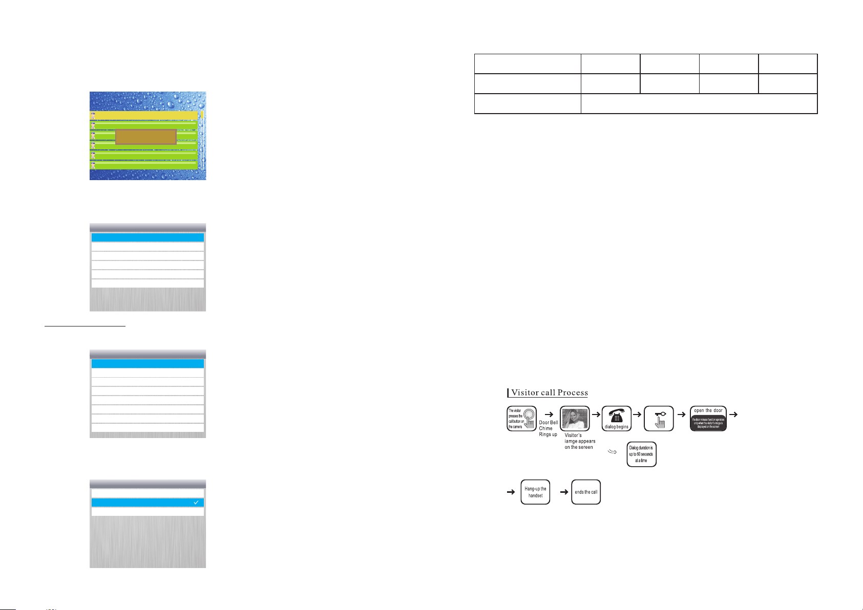
Ⅳ: De lete the reco rdings
If you want to delete the recorded files, you can use UP DOWN
and ENTER keys to select the file, then press # , the file will be
" " " "
" "," "
deleted.
UNAN SWERED FILE LI ST
Inne r Memor y have 2 fi les tot al.
7- 1- 201 0- 00 2 20 :0 5:0 0
7- 1- 201 0- 00 1 20 :0 0:0 0
Need y ou del ete thi s file?
Con firm Pl ease en ter OK!
V: S ettings
If you go into Settings , you will see this menu." "
Sys tem Set ting
Gen eral Se tting s
Def ault Se tting R estor e
Sto rage Se lecti on
Dis k Info
For mat
Abo ut
>
>
>
>
>
>
General Settings
" "
In General Settings , you can see :
Gen eral Se tting s
Lan guage
Aut o Recov er
Dat e Setti ng
Tim e Setti ng
Dat e/Tim e Forma t Setti ng
Min imum Al arm Spa ce
Pow er Off Ti mer
Dis play Se tting
>
>
>
>
>
>
>
>
3 . INTERPHONE: 4PIN connection, for extended audio handset;
Wire No.
Wire Definition
Recommended Cable
1
Audio
2
GND
DC Power
AWG #22-26
3 4
Intercom
Wiring Precautions
1. If high voltage cable is present in the vicinity, use a coaxial cable
with metal outer casing.
2. If any external wiring is exposed, it may cause a short and become a
cause of malfunction or fire
3. When connecting the monitor and camera, make sure that the
monitor power is off.
(Turn on the power after plugging the AC power cord into the outlet)
OPERATION
1.S etup Color, B rightness
Switch on the monitor, press Color Key, or Brightness Key or
Contrast Key at the side, then press Up Key ( ▲ ) or Down Key( ▼ ) in
the front to setup proper color, brightness or contrast accordingly for
the screen.
2.V isitor's Ca ll
" "
In Language setting, you can choose a language for all menus from
Chinese, English and Arabic.
Lan guage
简体中 文
Eng lish
Ara bic
>
7
4
Page 6
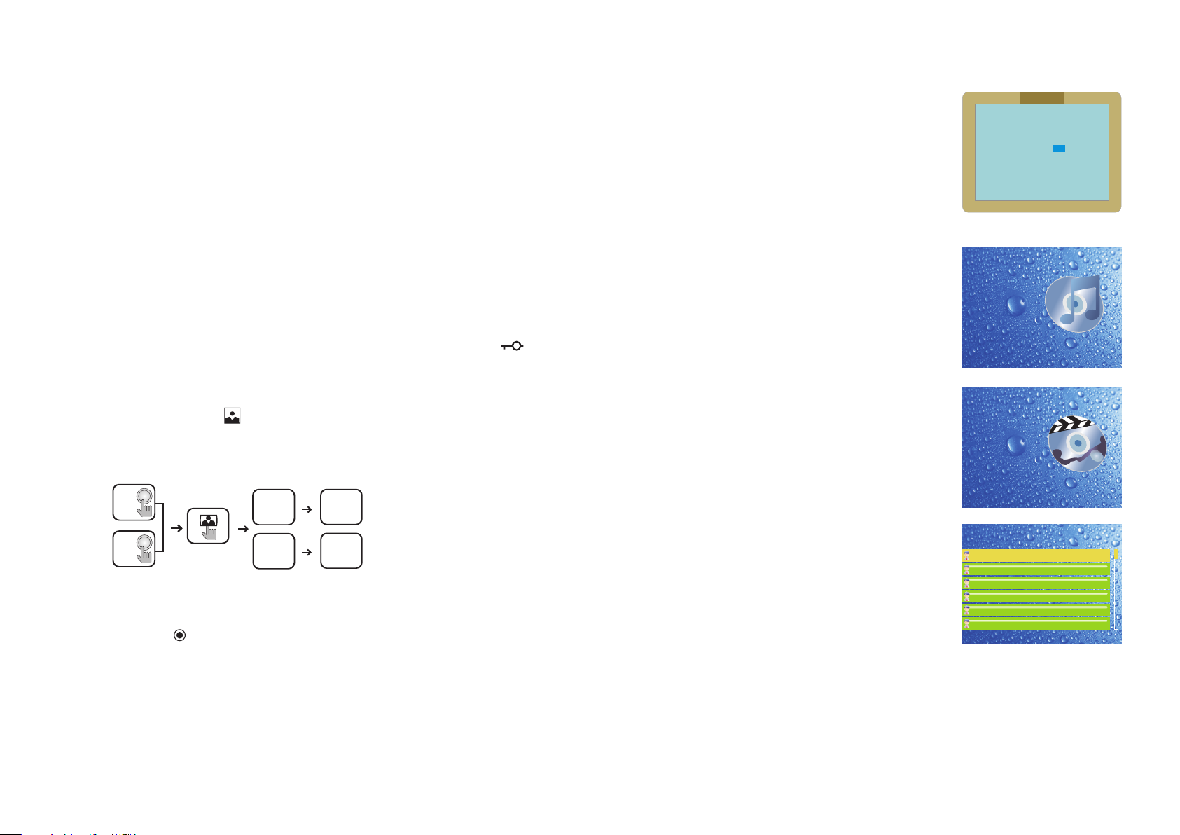
Switch on the monitor power.
1. When a visitor presses the "Call button on either camera unit, the
"
monitor' speaker will sound a "chime" tone to announce that a visitor is
at the door.
2. Upon viewing the monitor's screen and the visitor's image, you have
two choices;
A. You can choose to "not respond" (by not lifting the handset) the
visitor's image will disappear from the monitor's screen within 20
seconds.
B. You can choose to "respond by lifting the handset and talking to the
"
visitor as if uses a telephone. The visitor's image will remain on the
monitor's screen for 60 seconds or until the handset is replaced Back
into the cradle.
3. After speaking with the visitor, and if you have installed an
electronic door locking system, you can push the "Open button ( )
"
to electronically unlock the door.
3. M onitoring
Press Monitor Button ( ) for the first time, the screen will display
the video from camera 1, second time, the screen will display the video
from camera 2, third time, end the monitor,
¬
Cam era 1
Cam era 2
Pre ss once
Pre ss twic e
Camer a 1 view
Camera 2 view
The l amp is
bli nking o n green
col or.
The l amp is
¬
bli nking on orange
col or.
4. I ntercom
If an extension handset is installed with this monitor, you can press
Intercom Key ( ) to call the handset to start an internal intercom.
Also this monitor can be called form extension handset(s).
5.I nternal Mem ory Operati on
Ⅰ:Standby:
In the standby status, the screen displays
calendar.
After a period of time if there is no any
action with this device, the screen will be
switched off, you can press EXIT key to
" "
activate the calendar screen.
II :Visitor' s Call:
All the visitor's call will be recorded
automatically, both video and audio.
If the call is answered, the recording file
will be saved Answered File .
" "
If the call is answered, the recording file
will be saved Unanswered File .
" "
II I:Playbac k the recordi ngs
At standby mode, press ENTER to see
" "
the main menu. There are three entries:
" " " "
Answered Files , Unanswered Files and
" " " " " "
Settings . You can use UP and DOWN
keys to select an entry, then press ENTER
" "
key to go inside.
In "Answered Files" or "Unanswered
Files" folds, you can see a file list, each file
is labeled with time. Use "UP" and "DOWN"
keys to select a file, the press "ENTER" key,
you will see the playing of the recorded
files, until you press "ENTER" key another
time to stop. When the file is playing, Press
" "
INTERCOM key to stop playing file, if
" "
press ENTER key, replay the file; if press
" "
INTERCOM key again, then come to file
list.
calend ar
Toda y is 07-0 1-201 0 00:0 0:00
Cur rent Da te is 07- 01-201 0
Sun Mon
Sun Mon
4
5
4
5
11
12
11
12
18
19
18
19
25
26
25
26
Ans wered File
Una nswer edFil e
Set ting
Ans wered File
Una nswer edFil e
Set ting
UNAN SWERED FILE LI ST
Inne r Memor y have 1 fi le tot al.
7- 1- 201 0- 02 6 20 :0 0:0 0
Thu
Wed
Wed
7
7
14
14
21
21
28
28
Fri Sat
Thu
Fri Sat
1 2 3
2 3
8
9
8
9
15
16
15
16
22
23
22
23
29
30
29
30
10
10
17
17
24
24
31
31
Tue
Tue
6
6
13
13
20
20
27
27
5
6
 Loading...