

Page 1
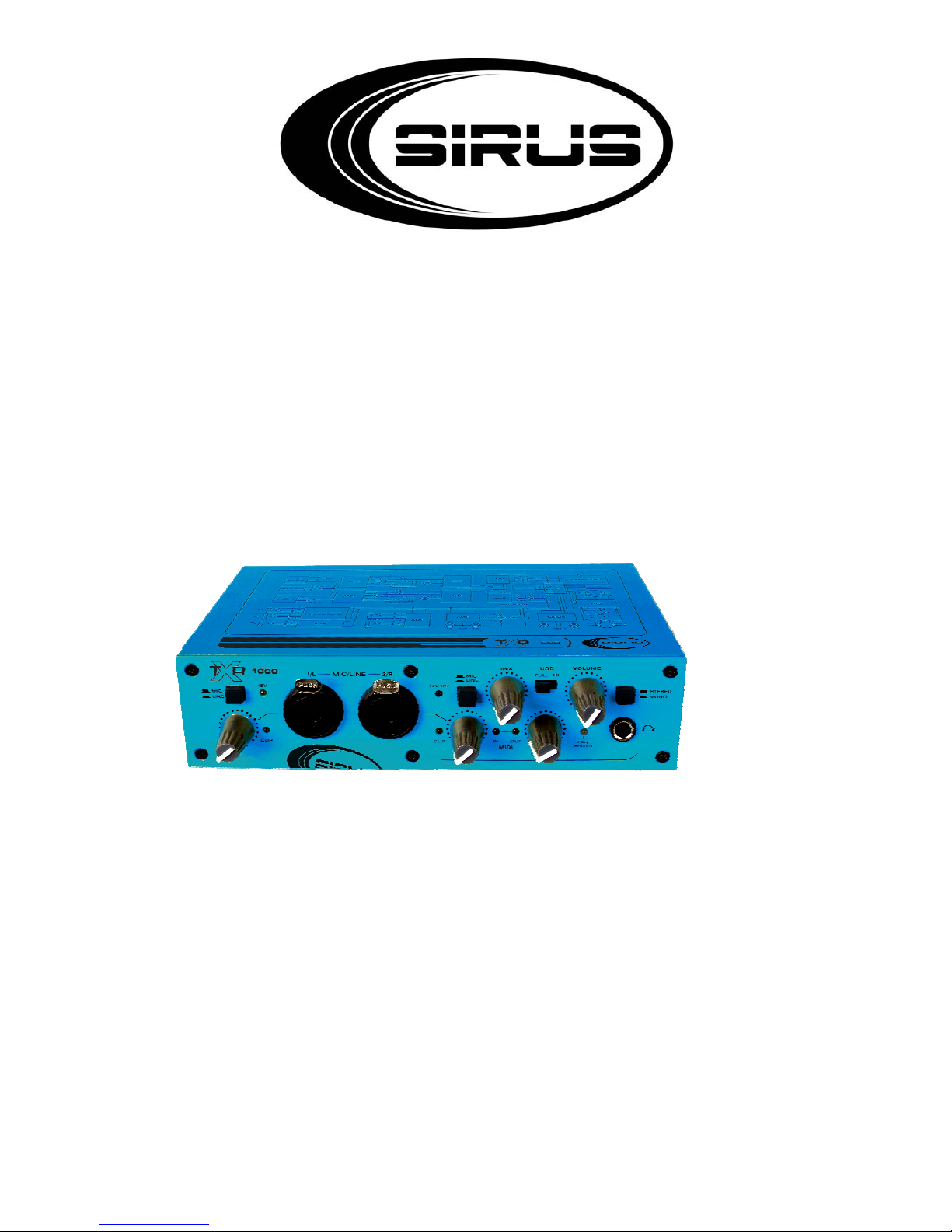
User’s manual
TX 1000
Digital Audio Interface
Page 2

2 / 9
Table of content
1.
Safety instructions........................................................................................................................... 3
2. Front View.......................................................................................................................................4
3. Backpanel.......................................................................................................................................6
4. Technical Data................................................................................................................................8
Page 3

3 / 9
1. Safety instructions
FOR SAFE AND EFFICIENT OPERATION
Be careful with heat and extreme temperatureAvoid exposing it
to direct rays of the sun or near a heating appliance.
Not put it in a temperature bellow 41°F /5°C, or exceeding 95°F /35°C.
Keep away from humidity, water and dust
Do not place the set in a location with high humidity or lots of dust.
Containers with water should not be placed on the set.
Keep away from sources of hum and noise
Such as transformer motor, tuner, TV set and amplifier.
To avoid placing on un-stable location
Select a level and stable location to avoid vibration.
Do not use chemicals or volatile liquids for cleaning
Use a clean dry cloth to wipe off the dust, or a wet soft cloth for stubborn dirt.
If out of work, contact sales agency immediately
Any troubles arose, remove the power plug soon, and contact with an engineer for repairing,
do not open the cabinet by yourself, it might result a
danger of electric shock.
Take care with the power cable
Never pull the power cable to remove the plug from the receptacle, be sure
to hold the plug. When not using the player for an extended period of time
be sure to disconnect the plug from the receptacle
.
Page 4
4 / 9
2. Front View
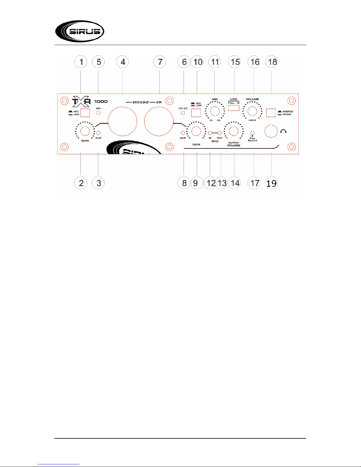
1. MIC/LINE-This button selects the mode of signal input for one channel(4).In the out position, the
inputs are set to accept the mic signal. In the in position, the inputs are set to accept line input.
2. Input Gain Level Knob(GAIN)-this knob can adjust the input gain level of one channel (4).
3. Clip Indicator LED(CLIP)-The Clip LED will illuminate red when the input signal from one channel(4)
is big enough.
4. 1/L MIC/LINE-This connector is a combo connector for mic input or line input. When the button of
MIC/LINE (1) in the out position, the connector can accept any microphone signal in standard 3p
balanced XLR or high impendance instrument level signal on an unbalanced ¼” TRS Plug with lower
input. When the button is in the in position, the connector can accept any line signal on a standard 3p
balanced XLR (Note the gain cant be too big) or high impedance instrument level signal on an
unbalanced ¼” TRS plug with high input.
5. 48V-It is an indicator for 48v phantom power . When the switch(25) is on, the light will be
illuminated.
6. 12V DC-When the power(22) is connected, the power switch(20) is on, the light will be illuminated.
7. 2/R MIC/LINE-This connector is a combo connector for mic input or line input. When the b utton of
MIC/LINE (1) in the out position, the connector can accept any microphone signal in standard 3p
balanced XLR or high impendance instrument level signal on an unbalanced ¼” TRS Plug with lower
input. When the button is in the in position, the connector can accept any line signal on a standard 3p
balanced XLR (Note the gain cant be too big) or high impedance instrument level signal on an
unbalanced ¼” TRS plug with high input.
8. Clip Indicator LED(CLIP)-The Clip LED will illuminate red when the input signal or PC USB from one
channel(7) is big enough.
9. Input Gain Level Knob(GAIN)-this knob can adjust the input gain level of one channel(7).
Page 5

5 / 9
10. MIC/LINE-This button selects the mode of signal input for one channel(7).In the out position, the
inputs are set to
accept the mic signal. In the in position, the inputs are set to accept line input.
11. Input/Playback Mix Level Knob(MIX IN,PB)-This knob controls the audio mix sent to the Line
Outputs, fading between the input signals and the output signal from your audio application software.
When it is in IN position, only the input signals are heard at the line outputs. When it is in PB position,
only the output signal from your DAW software is heard at the line outputs. When the mode is for
recording monitor, the knob is in the IN position, it is the direct monitor to the effect of the signal input,
the time delay is the minimum. The knob is in the PB position, it is the playback monitor to the effect of
the signal input, the time delay is the maximum.
12. MIDI INPUT(MIDI IN)-When the MIDI connector(24) has MIDI input signal, it will be illuminated.
13. MIDI OUTPUT(MIDI OUT)-When the MIDI connector(23) has MIDI output signal, it will be
illuminated.
14. OUTPUT VOLUME-This knob controls the output signal levels from
(19),(30),(31),(32),(33),(34),(35).
15. USB FULL/HI-This is a selector for USB speed. When it is in FULL position(USB2.0 full speed
mode), you can input/output 16bit signal, driver is no need, but the input and output of S/PDIF cant be
used on this mode. When it is in HI position, you can input/output 24bit signal, but you should install a
special driver first, after the installation you can choose your mode freely.
16. INPUT VOLUME-This knob controls the input signal levels from (4),(7),(28),(29).
17. Play/Record-This LED Light shows the signal of playing or recording. When it has the signal of
playing or recording, it
will be illuminated.
18. STEREO/MONO Button-This button toggles the direct input monitoring between stereo and mono
operation. In Mono
mode(IN Position),an input signal will be heard equally in the left and right of the headphones. In
Stereo mode(OUT
Position),input 1 will be heard in the left while input 2 will be heard in the right.
19. Headphone Output-This is a 1/4" stereo TRS jack, designed to drive a pair of stereo head phones.
Page 6
6 / 9
3. Backpanel
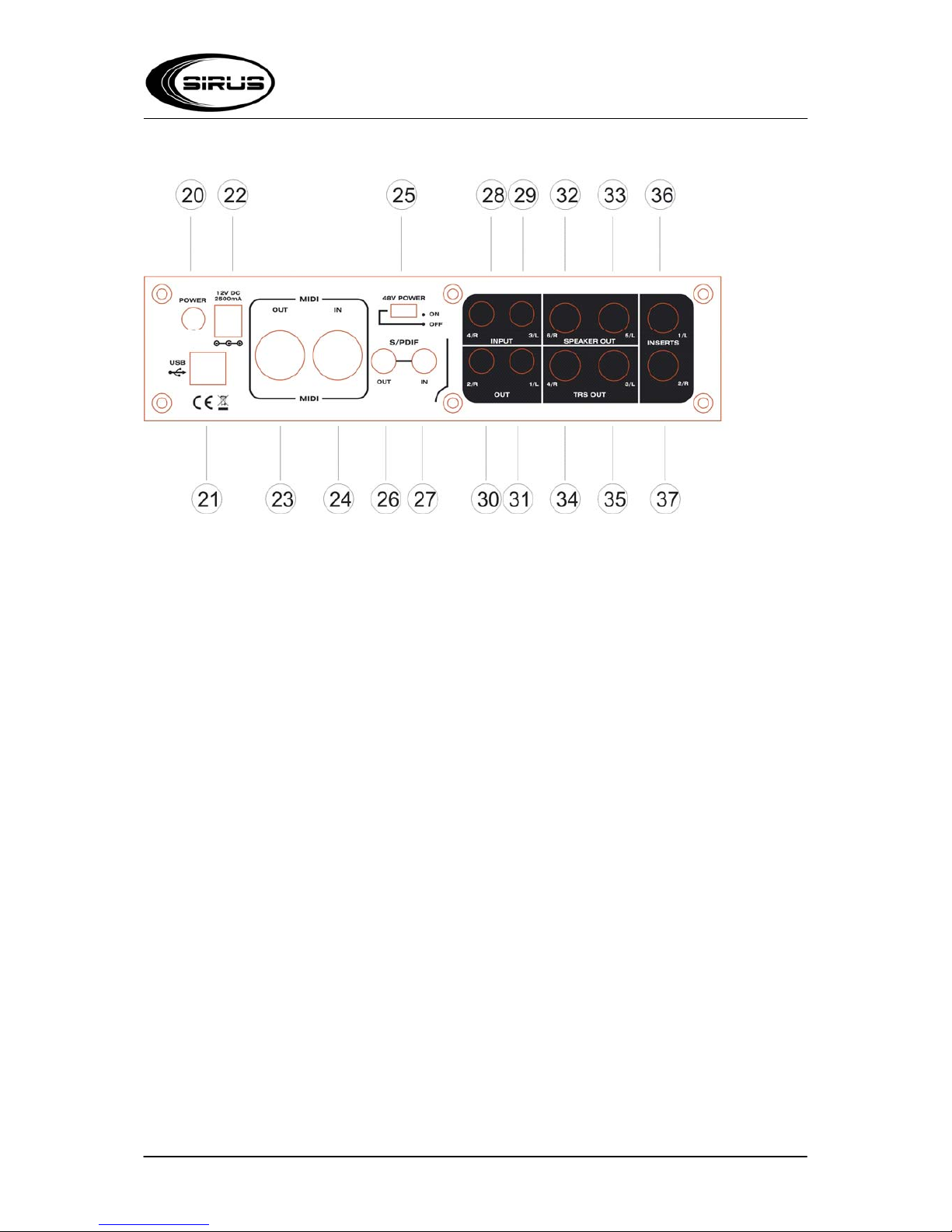
20. Power Button(Power)-Pressing this button will power on the DI800,the USB interface and the 12V
DC can work
normally.
21. USB Input(USB)-USB2.0 Port, connect a standard USB cable to this port, connecting the other
end to your host
computer .
22. 12V DC-This is an external power supply. If you want to introduce the signal from (32),(33) to
speaker , you have to
use this external power supply. If you don't use the speakers, it is unnecessary to connect the external
power supply.
23. MIDI OUT-Connect to the MIDI input of your controller or other MIDI device
24. MIDI IN-Connect to the MIDI output of your controller or other MIDI device
25. 48V Phantom Power(48v Power)-This button is for 48V Phantom power
26. S/PDIF Out-Digital output on coaxial(RCA type) connector .the attached soft driver must choose
the S/PDIF output mode correspondingly.
27. S/PDIF In-Digital input on coaxial(RCA type) connector . The mode of the recording software
should be selected the S/PDIF mode
28. 4/R Input-This is a RCA Input for RIGHT channel
29. 3/L Input-This is a RCA Input for LEFT channel
30. 2/R Output-This is a RCA Output for RIGHT channel
31. 1/L Output-This is a RCA Output for LEFT channel
32. 6/R Speaker Out-This is a signal output for the speakers with bridged way, the Minimax
impedance can be 4 ohm,
with short-circuit protection
Page 7

7 / 9
33. 5/L Speaker Out-This is a signal output for the speakers with bridged way, the Minimax impedance
can be 4 ohm,
with short-circuit protection.
34. 4/R TRS Out-this is a balanced signal output for TRS in RIGHT channel
35. 3/L TRS Out-this is a balanced signal output for TRS in LEFT channel
36. 1/L Insert-This 1/4" TRS jack are configured to connect an analog outboard effect for LEFT
channel(the selctor switch 1 mustturn to MIC position), inserting the effect
between the preamp and the A/D converter . The TRS Jack is configured as follows:
Tip=Send,Ring=Return,
Sleeve=Ground.
37. 1/L Insert-This 1/4" TRS jack are configured to connect an analog outboard effect for RIGHT
channel(the selector switch 1 must turn to MIC position), inserting the
effect between the preamp and the A/D converter . The TRS Jack is configured as follows:
Tip=Send,Ring=Return,Sleeve=Ground.
Brief Features: in addition to the multiple functions and flexible configurations, this item is with the
ASIO driver itself.
Method of installing the driver under USB2.0 HI: Firstly please turn the switch to FULL position,
connect the USB cable and turn on the power. When the signal light 17 is illuminated, please firstly
play some music and check if it can work properly. If it can work properly, then please find the driver
which is corresponding to your system from the attached DISC, then operate according to the
instructions.
Page 8
8 / 9
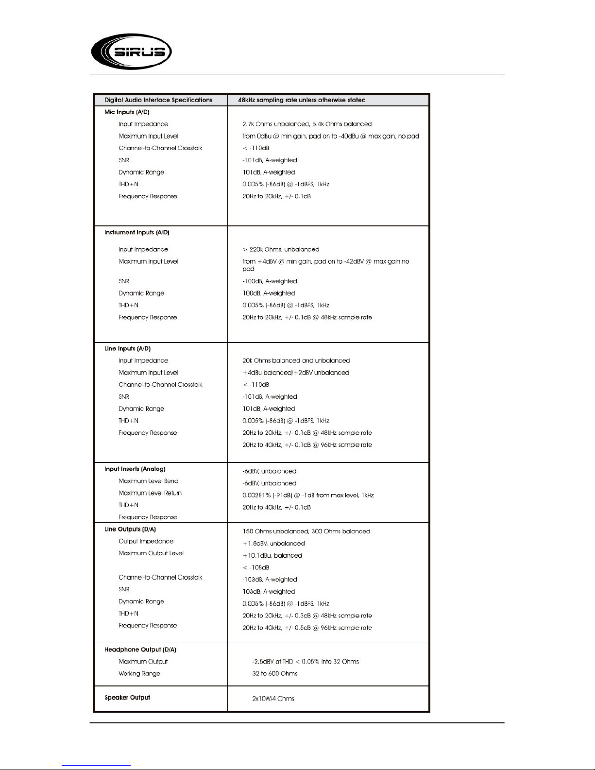
4. Technical Data
Page 9
9 / 9
Importeur:
B & K Braun GmbH
Industriestraße 1
D-76307 Karlsbad
www.bkbraun.com
 Loading...