

Page 1
R718K/R728K
R~Jii1~f!iPIIDaJ
KAULIN MFG. CO.,LTn
ffffl
~t3~
=!=W*f1=
li1
INSTRUCTION BOOK & PARTS LIST
c~-
'
~
-
_.
The specification and/or appearances
list
are
subjectto
change because
of
the equipment described in
of
modification
without
this
previous notice. ODM14P31.JUNE.2013
instruction
book
and parts
C€
-.....
0
.,
.
-
w.l
®
S~Jii1S3~1l~fJEJ
1&111
KAULIN
MFG.
CO
..
LTD.
Page 2

EC DECLARATION
OF
CONFORMITY
According to the following
Machinery
The undersigned, ROBERT TSAI , representing KAULIN MFG. CO
Sec. 3 Min Shen
machine described hereafter:
Directive:
E.
98 I
37
I
EC
, as amended
Road, Taipei , Taiwan ROC., manufacturer, declares that the
EC
Directive
by
8913361
EEC
and
731231
..
LTD.
EEC.
11
F 128
Post-Bed Lockstitch Machine
Model:
Provided that it is used and maintained in accordance with the generally accepted
codes
essential safety and health requirements
of
good
practice and the recommendations of the instructions manual, meets the
P700K/R700K
of
the Machinery Directive.
For the most
requirements
EN
292
design.
The
compliance
established
Belgium
Machinery Directive).
specific
of
the Directive has been based on elements of : the European Standard
- 1 & - 2 :
of
by
AIB-VINCOTTE Inter n.f.p, Avenue A. Drouart
( Notified
1992
the model with the requirements
body
risks of the machine, safety and compliance with the essential
Safety
under the number
of
machinery ; basic concepts, general principles
of
EC
Machinery Directive was
27-29, B 1160,
26
for machinery listed in annex
Date:
Signature:
Qualification : R&D MANAGER
AUG. I 1 I
W..,<....(
·
for
Brussels,
IV
of
EC
2006
L'
Page 3

INDEX
J{/PAGE
General
Warning ! When using this machine, basic safety precautions should always be followed
risk of fire,
Read all these instructions before operating this product and save these instructions.
1.Keep
Cluttered areas and benches invite injuries.
2.Consider
Do not expose power to rain. Do not use machine tools in
Dot not use power tools where there is risk
3.Guard
Avoid body contact with earthed
4.Keep
Do not let visitors touch the tool
5.Dress properly.
Do not wear loose clothing or jewelry, they can be caught in moving parts. Wear protecting hair covering to
contain
6.Do
not
Never carry the machine by cord or yank it
oil and sharp edges.
7.Maintain
Follow instructions
damaged have it repaired by
&.Disconnect
When not in use, before servicing and when changing accessories.
9.Avoid
Do not carry a plugged in tool with a finger on the switch. Ensure switch is off when plugging
1 O.Check damaged parts.
Before further use of the tool, a guard or other part that is damaged should be carefully checked to
determine that it
11. Warning.
The use of any accessory
present a risk
12. Have
Repairs should only be carried out by qualified persons using original spare parts.
Safety
electric
work
work
against
children
long hair.
abuse
machine
unintentional
your
shock
area clean.
area environment.
electric
away.
the
for
machine
will operate properly and perform its intended function.
of
personal injury.
tool
repaired
Instructions
to
and personal injury, including the following.
damp
or
wet locations. Keep work area well lit.
to
cause fire or explosion.
shock.
or
grounded surfaces (e.g. pipes, radiators, ranges refrigerators).
or
extension code.
cord.
to
disconnect it from the socket. Keep the cord away from heat,
with
care.
lubrication and changing accessories. Inspect tool cord periodically and if
an
authorized serviced facility.
starting.
or
attachment, other than those recommended
by a qualified
person.
in
this instruction manual, may
reduce the
in.
~J!~~~lj[~ijij
~~U~JJi
m~
fi.l5it
tt!Y-J~~
~-rz•rw
fifaailltiJlJtzmJ~WMa
•ttz~a
-~~~~JI:jl~
tt~B!i~Jijj~
~~B!i~Jijj~
a~mz~tt
jiJlJt11!1.J
tt•W~H~~·
$t
00
"Fi!flftjlij'JI~~
~1ymJJt~·
~filii
~!l
~HI
rdl!Jt
IMPORTANT SAFETY INSTRUCTIONS 1
WARNING 5
SPECIFICATION 6
LUBRICATION 7
INSTALL THE NEEDLE 7
ASSEMBLE AND DISASSEMBLE THE BOBBIN 8
OPEN AND CLOSE THE ROLLER PRESSER FOOT 10
THREADING
ADJUST THE THREAD TENSION 12
ADJUST THE NEEDLE THREAD TENSION
ADJUST THE
ADJUST THE STITCH LENGTH 13
ADJUST THE PRESSURE OF THE PRESSER FOOT
ADJUST THE NEEDLE BAR AND THE
THE CLEARANCE BETWEEN THE NEEDLE AND 16
THE
HOOK
ADJUST THE LOWER FEEDING ROLLER HEIGHT
ADJUST THE
TABLE CUT-OUT OF FLAT BED R718-T1 20
TIP
HOOK
HOOK
11
12
THREAD TENSION 13
14
HOOK
OPENER
14
18
19
Special
1.1ncorporate this machine only with
2.Follow the instruction manual device
3.Aiways earth machine
4.Before adjustment, parts change or servicing must be sure
the hazard of
Warning For
appropriately during operation.
unintentionally start of machine.
Electric
"CE"
to
Connection!
certificate hold-to-run control device.
install control device.
to
pull out the plug from socket to prevent
Page 4

IMPORTANT
IN
STR U CTI
0 N S
SAFETY
~~•••*~•~7~~a~•~•~•
~~~~~~~~a~~~~~~~~mm
at~
B.
~m"M~1-rllllilt~~m~~:;;.
1~H~~~WHfm'E:.
!Ill
f~
~
:Lti!
J'j.
1.
~1fll~m
fl!!~*
2:fim~tBM.
IHJ~X1~lfli&J~~
*fim~~~~~~~-~~~qw~
3. st m ~
Mfim~w.
4.~tlft3i;.s.Uif1=~1ilia~.
~~~~tt~~AA~~~~•"""Fa~~~
~twa~.
~
~11
11
w
~~2f~~JI:~~ijij~JJitt3~
~ 7
J.1
""F•:IR9~.
ntg_
~7m*fim~~•9~.
t!f.
Jl:~9~.
~~lififf:~
~~~Alii!~~
~~:iE
~
J5Jf~~~~~1il~~
~~
~):tmx
~i¥111
t'-
~fl.
For operating safely and to get the most out
of the many functions of this machine, you
must operate it
follow the instructions of this manual, and
keep it at hand for future references.
confident that you
much
1.When you use this machine,
2.Before using this machine,
3.Piease use this machine after it has been
4.1t
-:ft~~-
correctly. Please read and
We
are
will enjoy this machine as
as
we enjoyed manufacturing it.
please pay
attention to the basis safety measures.
please read this
manual and all related instructions.
addition, please save this manual for your
future needs.
ascertained that it conforms with safety
standards and
is not allowed to operate this machine
without the specified safety devices.
safety devices must be
regulations of your country.
in
right position.
In
All
(2)
.]I!
ftttJIIIA.ttti.~A.mtt
W
~.
J.1
& X
1i!!
11M
.Ill~
}=l,PJ1Pj\,]J[11J
f-1:
a~.
When the machine is ready for operation.
5.This machine must be operated by an
appropriately trained operator.
6.For your own safety, we suggest you wear
goggles.
7.
Please turn
disconnect it before doing the
tasks:
(1
).Threading needle(s), adjusting thread
Take-up(s), thread guide(s), and
replacing bobbin(s).
(2).Replacing needles, presser feet, needle
plates,
folders, cloth guides and other parts or
accessories.
(3).Repairing this machine.
(4).When
working
off
the
power
switch
following
I or
feed dogs, needle guards,
the
operator
place or when the working
is leaving the
or
(5).lf'fi.ll.l
~~~~it3i;~~.Lt.
M~H.~
it
iffi1llAA]J[
J:1
~iiq,
-1-
place
(5).While clutch motors without brake pads
are
completely stop.
is
unattended.
used,
motors
must
come
to
Page 5

8.fi~~~~-~&~~~ffl~····~
8.By any chance, if you allow grease, oil, or
••~~.•~•~••.~n•~*••
~
lillliHiL
&
5\.t
~-
any fluid contact your skin or eyes, please
wash the contacted area completely with
clean water and
consult a medical doctor.
.a~
15
~~t
ll
~
~
1±
m!
lE
'm
HH'F
~n.~
Ill
if~
.•
it~
:lim
IJI
"F
:~t
J\U!!L.l:.
i'F.
.•
15.To level the machine on the ground is
essential
operation
operating
in
order to ensure a proper
and
a
machine
lower
noise.
at
a
Avoid
noisy
If the fluid was swallowed
medical
9.~~~~~·~~~~~~-~~&A~
~-~~~:.!!!:a
10.*It~.~Gil&
-~H~-~~a~.H~-R~~fflfi:l
SIRUBA:f:t:i:JE:~~~-
11.-~M~&~WI~A·fi:l~~~~~
~.A.~a~.
12.-~*~M~&--I~A-EI=lft~~
~~.Uilia~
w.
~~~¥1!f~~:~~a~.
~
13.{£
~I&~
~&
~~A3l't 7 J.~&
Ill!
A~ 7 J.~~I(J)\!i
Rm!EI=l~~~~~-~H~-M~a~
~!ll
1Uii
B
rm
ii!l:.
~~~I
.•
fi:l~l''m~M~.A.~~-&~~
:;:~:
1Hii.
1'F.
\Wl
El=l
~~lfUCWil
~:u:~a~!l:-~ii
~f!f
<
i§!J
~~
~
ifi.D.
-~i!Ul~~-&
ll
~.ll~
~.
Jl:t:9~~~&1'1m!~W
~
9i:f:f
~
~ M
i!!1i
~
iWi
II!~
9.Do not touch any parts and devices in
motion
Always pay attention to whether power
switch is on or off before conducting any
task.
1
O.Qualified
machine adjustment, modification, and
repair. Only genuine parts from SIRUBA
are
Damage resulted
are subject to your own risk.
11.Routine maintenance and check-up have
to be performed by appropriately trained
persons, or qualified technicians.
12.Qualified
persons
electronic
electronic
adjustment or repair tasks. Stop the
machine immediately when discover the
failure
components.
13.The air hose has
machine and the compressor or air
has
servicing
pneumatic parts such as
Qualified
persons are required for adjustment and
repairs.
14.To
periodically clean up on the machine is
necessary.
contact
doctor
while the machine is running,
recommended
to
be cut off before repairing and
ensure
immediately.
technicians
in
technician
are
required
components
is essential
of
any
to
the
machine
technicians
the
are required for
for
replacement.
using generic parts
or
well-trained
for
services
knowledge
for
conducting
of
the
electronic
be detached from the
equipped
an
air cylinder.
or
well-trained
best
performance,
a
to
of
supply
with
surrounding.
1 6 .JI
ffl
~
~
~
11
~
:f!fi
iifl.
ilfi
El=l
11
~ H ~ ~
~
I&
{£
ll
~
J:.,
A
:tal
~l't
A
\Wl
:tal
{£
~
:tm.Jm
J:..
1 7
.•
~
R :ft
~ ~
~
ffl
~
II
:lE:
ffl
iti
J:.,
iti:.!!!:
~
:ft
~!f.~-
1a.~
Gil•
if£
ll
~A
\WI
1.ll:
n~
'ii:
~
m
~,
l~m
:lllHISl
~
~
~
'ii:
~
r.Ht!i.
:;j;:
f}
:!JIHEfoJ
:f.t.
~
~tJ
~
Gil• w £
ll
~
I'JT
sl
~--
1 9
.tH!l·
m
7.iU~
Rii
~ ~
lJI!l~
:if-:
(1J.~Ht1'F~·~~~.A.~~fl~~llfi:a
it~M~~~I!i.
~:9~a&~~•m~a~~oo~*~
a.~~~iiJ1':E~ImJSi~ii.
:eli
'ii:
~
l.ll
f!f
b.a
7
illt~~li~Uitt.~-Bll"~
.11l.l~~.iiUV.'L&n~.
1,\'li
&
Ji~
it,
11fffoJ~~-
~~Himf.ffiiUnUft
~:l'I!J'fijjii
fl,
i!Hi M
!It
:9H.~
~:II
f'F.
~~UI~fiili.
®
llB
fli
)j§J
Ill
:tl!!
~
;J;t;
ft!l
:JE:
&
FiJ
~
Jre
m
~
iiJ
;J;t;
~
ffl
~
:iJ:
:Iii
7
a
tDl
16.A proper power
this
connect the power plug
receptacle.
17.This machine can
designed purpose.
machine are not
18.Any modification or conversion made on
this machine must be conformed with the
safety
Precaution is necessary.
responsibility
modification
machine.
19.Two safety warning signs are
(1
(2)Aiways keep
plug must be used with
machine
standards
)For the safety of operators and service
persons,
any electronic
other devices and don't touch any
components inside
shock hazards.
Please never operate this machine with
belt cover, finger guard or any safety
device removed to avoid
a.Piease keep your hair, fingers and
cloths away from the hand wheel
"bobbin
while the machine is
prevent the risk of injuries
into them.
b.Piease never put your fingers under
the needle or
cover when you turn on the power
switch or operate the machine.
by
electrician.
to
only be used for the
Other uses of this
allowed.
and
for
damage
or
conversion
please don't open the cover of
control boxes of motor or
in
mind :
winder", V belt and motor
in
the thread take up
regulations.
We
applies:
to
avoid electrical
physical injury
in
Please
a grounded
assume no
caused
operation to
by
by
of
this
tangled
-2-
-3-
Page 6

c.
~1~Him
'1=1.
I§
ti~~-~9~-
d.
'i:IIHiiQ'i=l,ttBl~~-lh.~
~If-¥
1¥-J-=¥-'fi~iiRfUtB~IWID:.
ft-TH~.
e.
~
Jlti
1'
ili6llm
RJ
IHifl:roG.H
Wf
1~.HI{J
=¥
JJl
{±
8{±iiQ
tt
1¥-1
"'F
15
'1=1.
7i!t
ilJ!Ii31
il~~j}j!m
:roGfflile•:e~a~.
®;L
fl~.
~1Hil~19!
!1:~9~.
IHI8Iill
r,JJ.
,J,,L-~
~
J!tl
Hf-=¥
:ro2
I
MWH'i=!.
f.~ 7 jl~lfH~~~Ihffii
9~
I 'i:
It
H~
ttl
~
:roG
3
H~.~
lUI
f-'11 H ..
g.~*1fl!
M
1¥-1.
~-9~.
1¥-111
13
.Lt
AA
f1B
it?,
7
i!t~-H~~I&ID
~aiUif-'IIHtj~t.
51{.
H ~ fi!iifii.I.Oii.l;it,
H~
.Jiffi
it
1m
Bl.1ili
:m:
1'
i31
m
ilJtt~a
:it .&
Bl.1ifli
llH
fi'
lf
~
PI
ffii
i31 ® ilJ
ff
c.Piease never put your fingers under
the needle
cover when you turn on the power
switch or operate the machine.
d.While the machine is
hook
rotates at a high speed. Please
keep your hands away from
of
hook
your hands.
sure
e.Be
inside the machine when moving
raising the machine head to avoid
possible
f.Piease turn
machine before
head
the
due
g.The
while the machine is at rest if your
machine is
motor.
of
to
machine
careful not
or
V
belt
to
motor
this machine to avoid possible
or
in
the thread take
in
operation, the
the
to prevent
In
turn off the
while
physical injuries.
off
removing the belt cover and
to avoid
abrupt
So, please turn
start of this machine.
does
equipped
possible
addition, please make
power
changing
to
place
the
power
tilting the machine
possible
not
produce
injury to
of
bobbins.
your fingers
of
accidents
noise
with a servo
off
the power
up
area
the
I
the
1.~19!~-~~~afl.
~liJi.)l~llH.
s.~1fm
~J.RH''~~'ii•1'~~.
•m
-;~~tuttf'FM".
B.
~~~1fm~t
WARNING
Please
malfunction and
1.Ciean
putting this machine in operation for the
first time after set up.
2.Ciean
transportation.
3.Confirm
and phase (single
4.Confirm that the power
connected
5.Never use the machine where the voltage
type is different
on
6.Confirm
the machine pulley is correct.
Warning:
Before
adjustment, please turn the power
prevent accidents caused by
the
confirm
this
all
dust
that
the
motor
that
doing
sewing machine.
the
damage
machine
and oil gathered during
the voltage are set correctly
to
the power supply.
to
nameplate.
the direction
the
following
to
this machine.
completely
or
3 phase)
plug
the
designated
of
following
to
avoid
before
of
motor.
is
properly
on shown
the rotation
operation
off
abrupt
start
of
or
to
of
h.~ 7 B~Mit;LfB~.9U~1'~tt3
OOS5JIBU&Mflflf'FWH
i.
~ 7
ile
:eX
ji~MS:roGS-T.1tll"ffii
;L
ilJ
~~~
fa 9
~I
~
$t
+J]
Iff
~
jJjjt
I :jij
tJt
f-'
mi
H~.
ill
i31
J:
accidents
machine.
h. Never operate the sewing machine
with the
avoid
i.
Please turn the power switch
prior
disconnection
prevent
electric
components.
due
to
abrupt start of the
ground
electrical
to
the
possible accidents
shock
wire removed to
shock
connection
of
the power
or
damaged
hazards.
electronic
off
plug
due
in
or
to
to
-4-
-5-
Page 7

--------------------------------------------------------------------------------------------
SPECIFICATION
I
I
LUBRICATION
~ID[
m~
~§~~
_LT
..
~
..
~
~~
ffl~
ft~@J
..
~
fOe
~-rr~
Model
Specification
Stitching Style
R718K--{)
-~/One
~~
Needle
Lock Stitch
1/02
R728K
R728K
~~!fwo
Upper & Lower Roller
Feeding
~YES
Roller Diameter
Needle Feed
036,30,26
R718K-01~
No
NO
R718K-02~
$~~,~~,~#~~m~~OOz8~
Yes
Application Stitching decorative derby edge
and mid-thick fabric.
Max Rotating Speed MAX. 2500 S.P.M.
Stitch Length
Needle
Bar
Stroke
R718K-01 0-4.5
R718K-02
41mm
0-7
mm
mm
0-4.5mm
-16-20-24
-28-32
Needles
of
shoes, leather
~~~w~m~oo•-~~~~~~~~~
9m~•~x~~~~~~~~~~~~
~Ill
'
J.j_
iiii~H!I$
o
(1111.
!112,
1113)
When starting
idling a while, please lubricate the
after
indicated points and other joints enough as
the arrows
protect the machine life. (Fig. 1, Fig.
to
operate a new machine or
show
in the figures in order
to
21
Fig,
1111/Fig.
1
3)
;RWff~
¥¥~rr~
;RW~~
~~
~~~
~11
~ffl~
~l*R-t
~~~
~~wmm
§111-171~
1JDntl1f~
~~
~m~ME
Wt~
Thread Take-Up Stroke
68mm
Presser Foot Stoke
7mm/12mm
Lift
by
Hand/Knee
Type ofThread Take-Up
Hook
Needle Width
Needle
Ring Type
7j(
ZjS~@]~
-
ORGSN DPx5#16/SCHMETZ 134
Bed Specification 5181178 (mm)
Bobbin Winder
Stitch Length Adjustment
Auto Thread Trimmer
Lubrication
Thread
~~Attached
'fflittiW1f
~None
~~ntl
1tMI*~#20-40
~:a.rt~~t~,ti!fij~~
Push Button
Manual
Stitching System
Post-bed, Lockstitch, and
fjlf§~
3
fl3
400W '
Motor
Single or 3 phases,
~1/Table
1
Rotay Hook Horizontal Type
1.6, 2.0, 2.4, 2.8, 3.2
I Polyester #20-40
Poller Feed
112HP
400W, 1/2
-~~Wt~
HP
Clutch Motor
1112/Fig.
1.
¥~
~-~~~tt~mAti.~tiR*·~m
¥~tf~ ' 'OOti~tiiiHI!!l~A~
!i=il~JJ
2
' M
lt!R!IIift*B o (114)
!113/Fig. 3
INSTALL THE NEEDLE
1.
Single needle
Insert
the
Make sure the
right side, and then tighten the screw
(Fig. 4)
the needle into the needle hole of
needle bar until reaching the end.
needle groove A facing the
B.
-6-
-7-
Page 8

2.
!Itt
~-tt~tt~S~M-2tt~~~-~~
I!$
'
'ffJI~
M 2
tt
1m
l!!l
IUil&tiUI**B o
~AfJHa)
(IllS)
~
ii
' :jij
114/Fig. 4
2.
Two
needles
Insert
needle clamp until reaching the end. Make
sure the
facing two sides and opposite
other, and then tighten the screw
the needle into the hole
needle grooves A
of
of
the
the needles
to
each
B.
(Fig.
2.
*I-T2~
~*I.:r~~*I~~~~-~~M~'~a
~-~.:r~~~~ffi~~o®=~~Mm
V~®~~Hffi.D@-~ili,~iliq.
tt•I!V@2~JJ ' M!M~~1
li:
0 (117)
Ocm•
116/Fig. 6
2.
Assemble the bobbin
Put the bobbin in the bobbin case and
rotate the bobbin a
in the figure. Then
thread path
pressing spring tongue
®.
little as the arrow show
pull the thread from the
go
beneath the thread
<D.
and pull out
S)
!IS/Fig.
·-
------------------------------------------------------------------------------------------1
~T
z~!D
ASSEMBLE AND DISASSEMBLE
S
THE BOBBIN
--------------------------------------------------------------------------------------------
from the thread
pulled out from the thread hole, it
is
should be upon the thead pressing spring
@, and have the therad left about 1 0
long. (Fig.
hole@. When the thread
7)
IF/Fig.
em
7
1.
1.
ft-T2t.f.FiP
Hf~ll(A~ie
(1116)
,
llPRJIDlliift~B&ft-TC
o
-8-
Disassemble the bobbin
Pull the latch lever
bobbin case
Band
A,
and then take out the
the bobbin
C.
(Fig.
6)
3.
ftr112~
~tt~-~tt~~~-~-9~ft~21!!l
~Do
(!SIB)
-9-
3.
Assemble the bobbin case
Place the bobbin case
thread through the groove D of the hook.
(Fig. 8)
in
the hook and
Page 9

I
'--------------------------------------------------------------------------------------------
1
i !l!ti ;ZJJli
THREADING
'--------------------------------------------------------------------------------------------
~~A~*fiffi~~~~~*~AM~~M
~-HM~~-~~tt~n·~~fl~og
M~ I j..:J.~&~Xff;fi11=
0
(1119 I 11110)
OPEN
PRESSER
Turn
to
lift the roller presser
the
roller presser
AND
CLOSE
FOOT
the
presser foot lifting switch
foot~·
foot~
down, and turn it left
1118/Fig.
THE
ROLLER
Then, press
ffi
upward
8
~-~~m~~M~~~~~~ti~~·~
il~1
Ocm;Z,IJ~
ii~t/Single
o
(1111 1 11112)
Needle
Please thread as the sequence shown in the
figures.
after threading through the
11, Fig. 12)
Please left
the
thread
about
needle hole. (Fig.
10 em
to
open. For closing the roller presser foot,
reverse the
Fig.
10)
steps
to
have the result. (Fig. 9.
III11/Fig.11
1!19/Fig. 9
-10-
1!11
0/Fig. 10
-11-
11112/Fig.
12
Page 10
~~~'MMOO~MS~,~·~,~~
il~-illl
A.
ii'I:!RJI
B.
$tM:i\.M
C.
tt*i:i\.Ji
0
(11113)
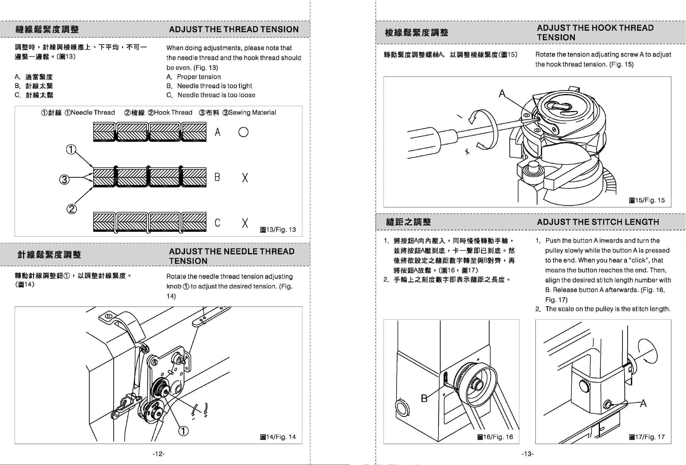
ADJUST THE THREAD TENSION
When
the
be even. (Fig. 13)
A.
B.
C.
doing
needle thread and the hook thread should
Proper tension
Needle thread is
Needle thread is
adjustments, please note that
too
tight
too
loose
I
I
--------------------------------------------------------------------------------------------·
ADJUST THE HOOK THREAD
TENSION
Rotate the tension adjusting screw A
the
hook
thread tension. (Fig. 15)
to
adjust
CDtt*l
(j)Needle Thread
®~•
-AO
-c
Q~ti·~~O(j)'~~~ti-~Jfo
(11114)
®Hook
Thread
@:ffi'fl
@Sewing Material
B X
X
ADJUST THE NEEDLE THREAD
TENSION
Rotate the needle thread tension adjusting
knob
CD
to
adjust
14)
the desired tension. (Fig.
11113/Fig.
13
1.
~~lHAraJ
.tt~~&AI!
~~~~~z•~•*M¥OOB~•'M
HfniaHAl&fi
2.
=FM~z~m•*~~~•~zAm
P-1
ItA. '
~rJ
Ja
'
o
(11116 ' 11117)
lii.l~1i11Qih=FM
-F
-§fin
a
~rJ
Ja
o
o
'
~
11115/Fig.
15
ADJUST THE STITCH LENGTH
1.
Push the button A inwards and turn the
pulley slowly while the button A is pressed
to
the end. When you hear a "click", that
means the button reaches the end. Then,
align the desired stitch length number with
B.
Release button A afterwards. (Fig. 16,
Fig. 17)
2. The scale on the pulley is the stitch length.
-12-
11114/
Fig. 14
11116/
Fig. 16
-13-
11117/
Fig. 17
Page 11
--------------------------------------------------------------------------------------------
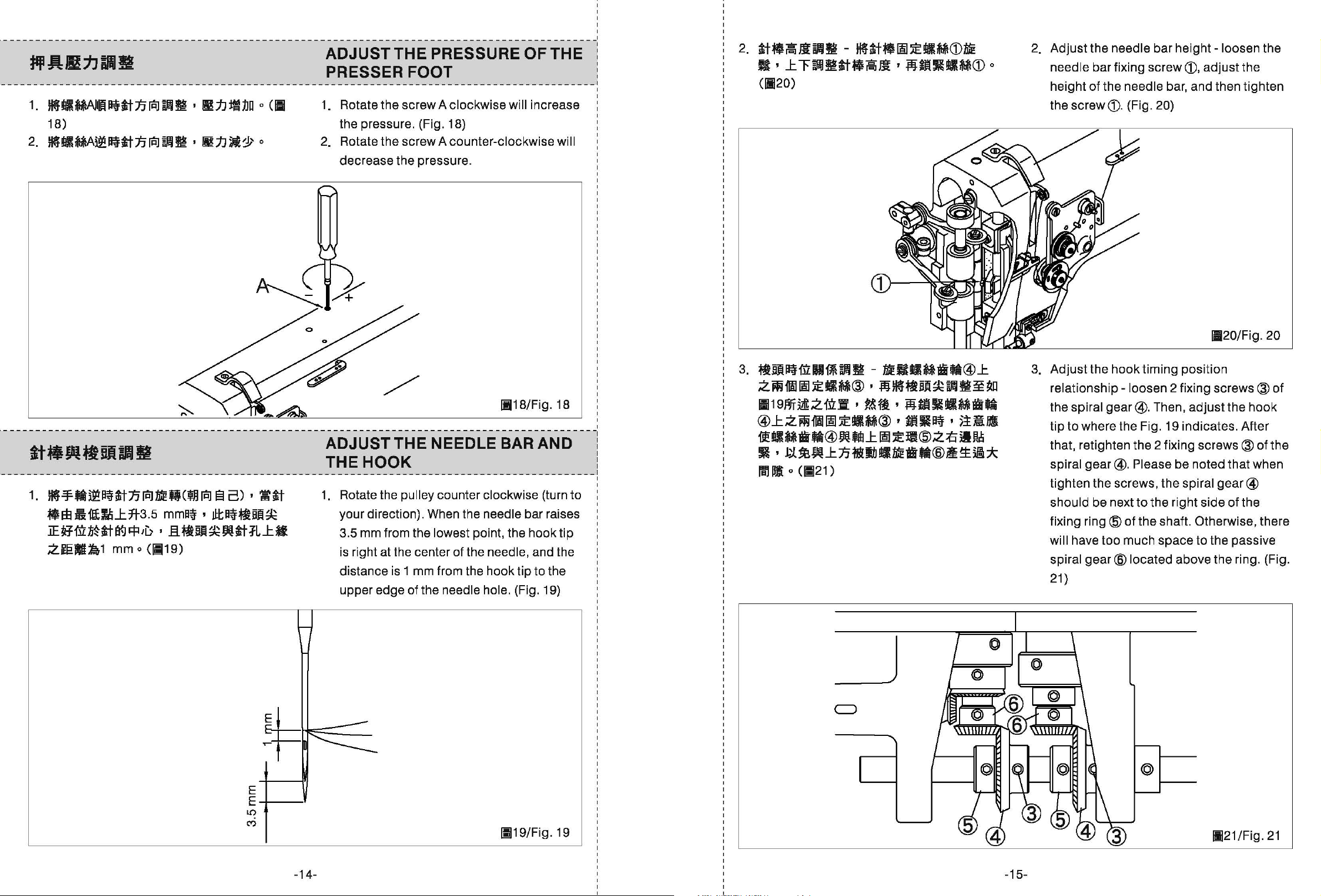
ADJUST THE PRESSURE OF THE
PRESSER FOOT
1.
1.
~!ll~l~tt:nraJ~!I
18)
2.
~·~im~ttnraJim~
I
~n~1Jo
I
~Mn)i~
o
o
<II
Rotate the screw A clockwise will increase
the pressure. (Fig. 18)
2.
Rotate the screw A counter-clockwise
decrease the pressure.
wi
II
I
I
2.
2.
ttlfiSMillJ!i
B'L~~~tilfiSM'M--M~CDo
(11120)
-
~tt·llii~!IIMCDME
Adjust
needle bar fixing screw
height
the screw
the needle bar height
of
the needle bar, and then tighten
(j). (Fig. 20)
CD.
adjust
-loosen
the
the
1.
~=Ff~H~~ttnraJMEQC~
•w
ii1ltrJiL7t3.5
~&mMti~~~~H~mi~WtiRLa
.Zielf~1
mm o
mma~ ' JI:ta~~ml~
(!1119)
raJ
13
c) ' 'i:tt
ADJUST THE NEEDLE
THE
1.
HOOK
Rotate the pulley counter clockwise (turn
your direction). When the needle bar raises
3.5 mm from the lowest point, the hook tip
is right at the center
distance is
upper edge of the
1 mm from the hook tip to the
J
11118/Fig.
BAR
of
the needle, and the
needle hole. (Fig. 19)
AND
18
to
3.
~ml~ruH~im·-~--~-~@L
.Z~M~~-~@~M~~ml~~~~~
II19PJT~z
@LZ~M~~!IIM®,m•q,~~
~-~-~@ft~Lili!~~@.Z~~~
·~~~WLn-~U~§~@~~~*
0
ra,
Ill
'fiLii
(11!21)
I
~fl
,
MillM!IIMata
3.
Adjust
relationship
the spiral
tip
that, retighten the 2 fixing
spiral
tighten the screws, the
should be next
fixing
will have too much space
spiral
21)
the
hook
timing position
-loosen
gear@.
to
where the Fig. 19 indicates. After
gear@.
ring@
gear@
Please be noted that when
to
the right side
of the shaft. Otherwise, there
located above the ring. (Fig.
2 fixing
Then,
11120/Fig.
screws@
adjust
screws@
spiral
to
the passive
the
hook
gear@
of
the
of
20
of
the
E
E--'----1
L{)
C")
-14-
11!19/Fig. 19
_j
-15-
11121/Fig.
21
Page 12
--------------------------------------------------------------------------------------------1
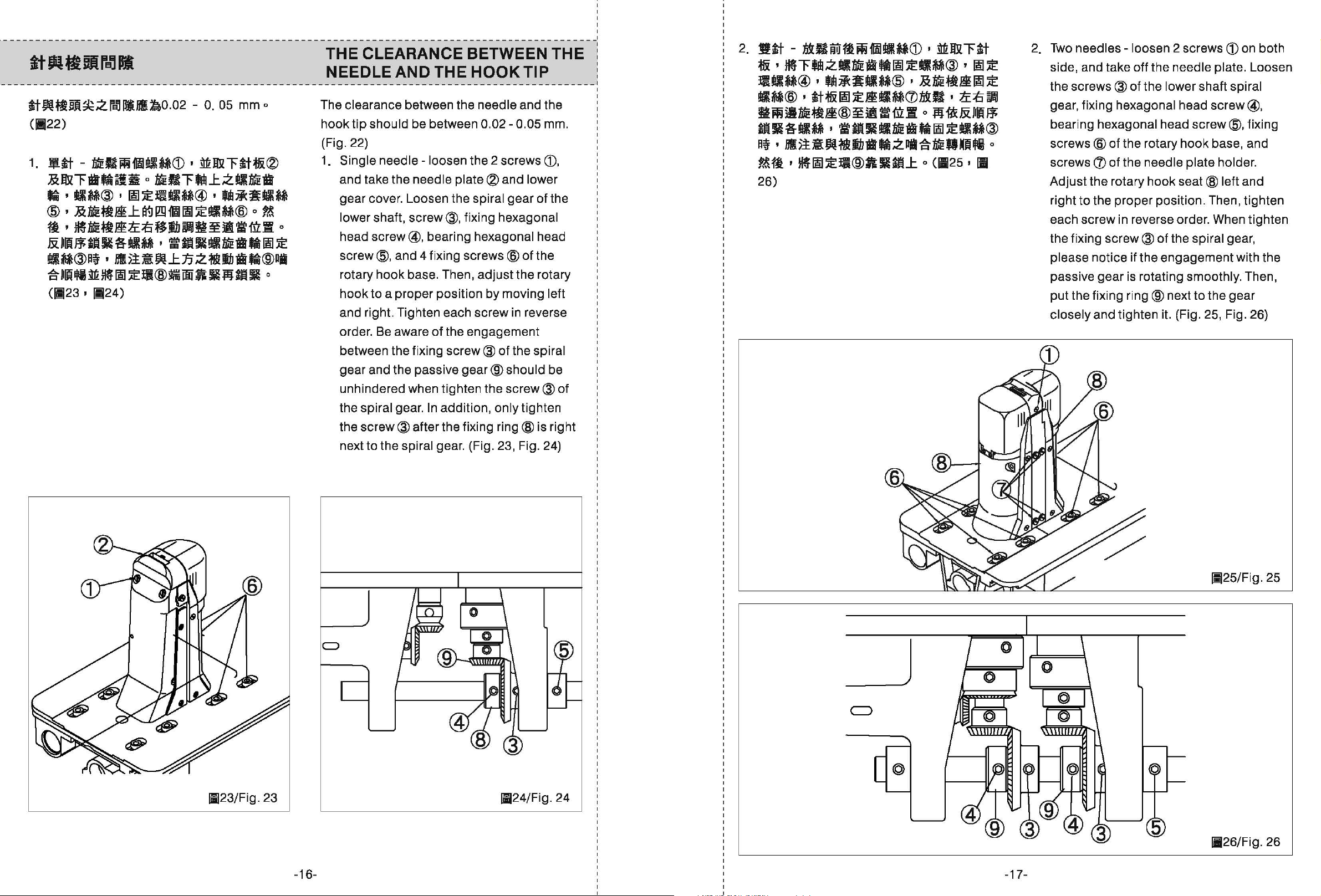
THE CLEARANCE BETWEEN THE
ttW~BJi~.:ZrdliJIS:1a0.02
(1!122)
1.
¥~-~•~oo~~~~~w~~~®
~w~••~~o~-~~L.:z•~•
··-~@·~~~~~@·~~~-~
@·~~~~L~~M~~-~@o~
~~~~~~~~3~~~¥~•mxo
-
o.
05 mm o
&~8-R&M~·=·-~~--~~
•M@q·a~~~L~.:Z-~8·®~
&~~~~~~~@~00~-~~-0
(11123
' 1124)
NEEDLE AND THE
The clearance between the needle and the
hook
tip should be between
(Fig. 22)
1.
Single needle
and take the needle
gear
cover. Loosen the spiral gear
lower shaft,
head
screw@,
screw@, and 4 fixing screws
rotary
hook
and right. Tighten each screw
order.
between the fixing
hook
to
a proper position by moving left
Be
-loosen
screw@,
bearing hexagonal head
base. Then,
aware
of
HOOK
0.02-
the 2 screws
plate®
fixing hexagonal
adjust
the engagement
screw@
TIP
0.05 mm.
and lower
of
@of
the
the rotary
in
reverse
of
the spiral
CD.
the
I
2.
Two
2.
Wtt-~BAA~~~-M~·~~~tt
~~~~~.:z·~·-~~-~@·~~
~-~@·~~~MM®·~~~~~~
•M®·tt~~~~~~~~-~~~~
~~~~~~@~~=m•o~•&•8
m~&MM···~-~--~~-M@
q,a~~w•tia•.:z~*~Qm~o
?&~'
26)
H~~~li®AR.L
o
(1125'
1B
needles-
side, and take off the needle plate. Loosen
the
screws@
gear, fixing hexagonal head screw@,
bearing
screws@
screws~
Adjust the rotary
right
each screw in reverse order. When tighten
the fixing
please notice if the engagement with the
passive gear is rotating
put the fixing
closely and tighten it. (Fig. 25, Fig. 26)
hexagonal head
to
the
loosen 2 screws
of
the lower shaft spiral
screw@,
of
the rotary hook base, and
of
the needle plate holder.
hook
seat@
proper
screw@
position. Then, tighten
of
the spiral gear,
smoothly. Then,
ring@
next
to
CD
left and
the
on both
fixing
gear
gear
and the passive
unhindered when tighten the
spiral gear.
the
screw@
the
next to the
In
after the fixing
spiral gear. (Fig. 23, Fig. 24)
gear®
addition, only tighten
should be
screw@
ring@
is right
of
11!25/Fig. 25
_j
11123/Fig.
23
-16-
1124/Fig. 24
-17-
11126/
Fig. 26
Page 13

--------------------------------------------------------------------------------------------1
ADJUST THE LOWER FEEDING
ROLLER HEIGHT
1.
1.
!itt
-
~"""Fti~JBHlUi*(flJJ)
fl~~~*!IIM®~~fl~~m*~~~
~~-~®·~!II~®TQti~~~~*
~~~@J.j_~~~fl~.:Z~Jl(ll27)
'
~-~
Single
the rotary hook seat (in the rear). Loosen
the
and the fixing
needle-
screw®
take off the side cover
of
the feeding roller holder
screw®
of
the adjusting
of
I
2.
Jltt
-
~~~fl~~tf*A.:Z~ii!II~CD
~~~-MBLZ~~~~!II~®'~
fl
' L
"""F311l~*~·~BUI~.:Z
tt~m•~fl·~~*•~oo~~~~fl
MCW~~.
mm
o (1128 '
MBrd:l L """F
11129)
.:Z
rdl
o
~!l
lft~O.
5
knob of the feeding
screw driver to adjust the feeding
height by turning the adjusting
the feeding
2.
Two
needlesthe feeding roller holder A, and the 2
screws®
moving the feeding
to
adjust. After that, tighten the screws
of
the feeding roller holder
the distance between feeding
feeding gear
29)
roller holder. (Fig. 27)
of
the feeding gear
B to be 0.5 mm. (Fig. 28, Fig.
roller holder. Use a
11127/Fig.
loosen the 2 screws
roller B
27
up
A,
roller
knob@
B.
Then,
and down
CD
of
of
CD
and adjust
roller C and
()
11129/Fig.
29
--------------------------------------------------------------------------------------------
I
~1\J~:J!I:iJJfi
I
tiQ~Mm~~~~A®ft~Mti*~~z
lli·A·ti·~-~~$U~@·Q~~~$
@'
iflmAW~:BJi~zrd:!Pl~0.1-
0.3
mm o
(ia30)
ADJUST THE
Rotate the
opener is at the position
from the
@of
the opener adjusting ring. Rotate the
adjust
opener
(Fig.
pulley until the stroke
needle plate. Then, loosen the screw
ring@) and keep the distance from the
to
the hook
30)
HOOK
A,
tip
to
be
OPENER
the farest point
0.1- 0.3 mm.
of
the hook
-18-
11128/Fig.
28
-19-
11130/Fig.
30
Page 14

TABLE CUT-OUT
OF
FLAT BED R718-T1
CONTENTS
§-m
/A.
L
1020
716
1\)
0
~
0
l
ll
~
4
~
R1
~
(
V\
·
A-A
HUifii
__J_
~=n
I
I I
I I
I
4-R19~
2-R19~
,/
~
p
U1
c-.
;;i
ts-
I I
i\4-R10
I
I
~
_]
J
A
T
(/)
1"'1
3::
.....
I
(/)
c
ID
~
::0
G)
1"'1
0
1.*1t1~fUR~~Ji*ftf:
2.--~~--
3.¥fillJ:B#.m•m
4.Mti*RilfM
5.7C~I!-
6 .J:
.W
~
.11l1!#
M
tl
tl
1 .J:ii,D-I!M
a.tt•••
9.~.5lMI!tl
1 O.jlfl1ftl.
1 1
.ez
i!Wi11i1l
12.1113~~--
1 3
.•
i!11:11J~t•
~t
m
MAIN FRAME
THREAD TENSION MECHANISM
SINGLE DIRECTION BEARING SHAFT MECHANISM
ROLLER PRESSER FOOT MECHANISM
THREAD TAKE-UP LEVER MECHANISM
UPPER SHAFT AND BALANLE WHEEL MECHANISM
UPPER SIDE SHAFT MECHANISM
NEEDLE BAR MECHANISM
NEEDLE BAR FEED MECHANISM
PRESSER FOOT BAR MECHANISM
TIMING BELT DRIVING MECHANISM
STITCH ADJUSTER MECHANISM
FEED SHAFT MECHANISM
AND
COVER PARTS
22
24
26
28
30
32
34
36
38
40
42
44
46
I~
1/
•
262~
195--
A 180
l
r--
40
0
R20 R25
~
I~
.....
0
1
~
~
//
/!)
I/
.6'
v
c c
~
It>
j
0
~
..,....,
I
II
~
)'
.1.
·
.....
lf-o
11
COl-"
I-"
w~--"1\l
t11CO
w
~
......
I
A
1 4-R6?
1\)
:b
.....
.I .I
1\)
0
U1
3-¢8.
jm
+
r--
1~
-f
~
f=
ss-cvr
I
1\)
·
Hl
co
U1
(J)
coo
W
t110
[t;
c-c
5
395
¢19
~
~
~~
¢18
320
311
236
189
162
5
5
ti
m
¥
50
d
.
11
~~
CO<O
OOt>
'U1
.j
t11
~
0
~
lj
R17
0
14.Mttifti'IM
15.¥~~~--
1
6.~Jm11M1111JIIM
11
.lcil~~
1B.lci~Jm1111JIIM
1
9.~il.mHIIbllfM
2 o .¥fill
21
.~ii.JIHIIJJIIM
22.~J*j!jc#
2 3
.!Jf;J
f-1:
2 4
.IJ!JJIHI
~mHiiD~tm
11
M11111
liM
CLUTCH SET MECHANISM
BEDPLATE FEED MECHANISM
BEDPLATE GEAR FEED MECHANISM
LEFT
LEFT BEDPLATE FEED MECHANISM
RIGHT SIDE BRACKET MECHANISM
FEED MECHANISM
RIGHT BEDPLATE FEED MECHANISM
SPECIAL PARTS
ACCESSORIES
PRESSER FEET
AND
MIDDLE FEED MECHANISM
48
50
52
54
56
58
60
62
64
66
68
-20-
-21-
Page 15

Sii=IUBFI
PARTS
LIST
Series
R718K/R728K
Subject
MAIN
FRAME
AND
COVER
PARTS
*lltlm~Htii*ftJ:
Page
1/2
Date
2013/6/27
Sii=IUBFI
PARTS LIST
Series
R718K/R728K
Subject
MAIN
FRAME
AND
COVER
PARTS
*lltlm~Htii*ftJ:
Page
2/2
Date
2013/6/27
1
9
I
~
-~
-8
Ref.
No
1 119687
2
3
4
5
6
7 314946
8
9
10 118430
11
14 119686
15
16
17
18
19
Part
108246
108234
168061
210210
119027
119039
700335
700335
700335
119092
108285-1
119091
108225
No.
Face
Plate
Screw
Screw
Thread
Screw
4
Hole
Screw
Arm
Side
Screw
Thread
Screw
Thread
Screw
Bracket
Screw
Bottom
Screw
Take-up
Thread
Cover
Guide
Guide
Cover
Name
Cover
Retainer
Wire
Wire
of
Part
Amt.req
R718K
liD~
~~*'*'
t-'*'*'
~H~
~~*'*'
II91U~MH*
~~*'*'
:k~.1Hi9>t&
~~*'*'
~~*~*
*'-*'*'
~~'R~*
~*'*'
l!i!IJEJf§ll:H
~*'*'
~~:lm
~~*'*'
1 1
1 1
1 1
1 1
1 1
1 1
1 1
1 1
2 2
1 1
1 1
1 1
1 1
1 1
2 2
1 1
5 5
R728K
Remarks
10-$
/
11
·-~
~
15
I
I
14
-22-
-23-
Page 16

Series
Sii=IUBA
PARTS LIST R718K/R728K
THREAD
Subject
TENSION
MECHANISM
Page
1/2
Date
2013/6/27
Sii=IUBA
PARTS LIST
Series
R718K/R728K
Subject
THREAD
TENSION
MECHANISM
--~~--
Page
2/2
Date
2013/6/27
2-
1
r
4
3
~~~
2-12
/
2-11
{)2-13
It
~
2-10~
2-9~
2-8---~
r
2-7
6-----0
2-11
~-5
FOR R728K
FOR R718K
Ref.
No
1 118553
2 119171
2-1
2-2
2-3
2-4
2-5
2-6
2-7
2-8
2-9
2-10
2-11
2-12
2-13
2-14
2-15
2-16
2-17
2-18
2-19
2-20
2-21
2-22
2-23
2-24
3
3-4
4
5 700412
6
Part
119171-1
119171-2
119171-3
119171-4
119171-5
119171-6
119171-7
119171-8
119171-9
119171-10
119171-11
119171-12
119171-13
119171-14
119171-15
119171-16
119171-17
119171-18
119171-19
119171-20
119171-21
119171-22
119171-23
119171-24
119766
119766-1
175096-1
700412-1
No.
Tension
Thread
Nut
Spring
Tensin
Thread
Tension
Thread
Screw
Thread
Tension
Tension
Tension
Screw
Tension
Nut
Upper
Thread
Thread
Thread
Thread
Thread
Screw
Tension
Screw
Screw
Thread
Thread
Screw
Screw
Bushing
Releasing
Tension
Guide
Spring
Take-up
Disc
Tension
Tension
Releasing
Releasing
Release
Release
Thread
Tension
Guide
Guide
Guide
Guide
disc
Tenison
Take-
Name
Regulator
Assy
Spring
Stud
Regulator
Plate
Spring
Tension
Stud
Bracket
Disc
Spring
Cap
Washer
Regulator
up
Sping
Pin
Pin
Pin
of
Plate
Part
Assy.
Bushing
Assy.
Amt.req
R718K R728K
~&
1 1
0 1
2 2
1 2
1 2
1 1
2 4
1 1
1 1
1 1
1 1
1 1
1 1
2 2
1 1
1 1
1 1
1 2
1 2
1 2
1 2
1 2
1 2
1 2
1
0 1
1
1 0
1 1
1 1
1 1
fi~m
~
~t5~!iliMJ.
!Ill~~
~~-*~
~~~-·
m~~••
~~-
~~!Ill**~
•**
~--~
fi*im
f§*i.m
~--;t&
!Ill~
~;t&~--
!Ill~~
J:.~
JM
::h
~~!Ill**~
~~~Le
~~~LIIIM
~~~--
~~~LI*Jji
!Ill~
~~~~-
!Ill~
!Ill~
¥~t5~!il*~
m~~••
!Ill~
!Ill**
ijllfJ.I
0
0
Remarks
(3-1~
21)
(3-1~
21)
-24-
-25-
Page 17

Series
Sii=IUaFI
PARTS LIST R718K/R728K
SINGLE
Subject
DIRECTION
~icJtS**lmMm
BEARING
SHAFT
MECHANISM
2013/6/27 2013/6/27
Page
1/2
Date
Sii=IUaFI
PARTS LIST
Series
R718K/R728K
SINGLE
Page
2/2
Date
DIRECTION
Subject
BEARING
SHAFT
MECHANISM
~icJtS**llll~tm
o-1
5
SJ-2
~
@)-3
o-1
-4
~-6
@--'{
©-8
u-12
-14
B-13
@)-8
©-7
~-6
u-12
-14
e-13
Ref. No
1
2
3
4
5
6
7
7-1
8
8-1
8-2
8-3
9
10
11
12
13
14
15
Part
No.
660290
119158
119158-1
756901
119150
119150-1
108294
640210
119159
119160
119886
119961
119962
119963
119507
174176
119087
061014
119505
119506
119503
Retaining
Bearing
Bearing
Bearing
Bearing
Bearing
Screw
E-Ping
Washer(l.O)
Washer(1.4)
Washer(0.1)
Washer(O.lS)
Washer(0.2)
Washer(O.OS)
Link
Ssrew
Oil
Felt
Needle
FreeFree
Shaft
Ring
Bracket
Bracket
Set
Set
Bearing
Wheeling
Bearing
Name
of
Part
C~t!:IJ.I
.IE:It&**~
(for·
t&**
.rE]t&***.H.
(for
·MS-119150) 1 1
·~~
E~t!:IJ.I
.E)
.E)
.E)
.E)
.E)
.E)
.IE:Iilff
·~*
5mmm
~tl!Xt&**
¥IE:It&**~
¥IE:It&***.H.
¥IE:It&**'lll
MS-119803)
Amt.req
R718K R728K
2 2
1 1
1 1
1 1
1 1
1 1
4 4
2 2
2 2
2 2
2 2
3 3
2 2
2 2
4 4
4 4
2 2
2 2
2 2
1 1
Remarks
(1~
3)
(12,
13)
@)-7
11
~>6
~-11
10
~,---10
~
11-~
-26- -27-
~
@-7
15
0
Page 18

Series
Sii=IUBA
PARTS LIST R718K/R728K
ROLLER
Subject
PRESSER
FOOT
MECHANISM
laJijftlt.
Page
1/2
Date
2013/6/27
Sii=IUBA
PARTS LIST
Series
R718K/R728K
ROLLER
PRESSER
la&j§lt.
Subject
FOOT
Page
2/2
MECHANISM
Date
2013/6/27
1 (Large)
I
4--
6-4-
6-5---'--
c
1
...
9-6
10-S
10-1-
10-S
11-~
20
\
~
@
I
-12
©-16
17
I
~
21
2 (Middle)
I
4--c
6-4-
6-5
---'-1
___
•
I
9-CQ)
I
10-~
10-1-@)
I
10-~
11--©
18
I
ytf
~
1@-16
11-~
~16
19
I
ytf
Ref.
No
1 119803
2
3
4 119469
5
6
6-1
6-2
6-3
6-4
6-5
6-6
6-7
7
7-1
7-2
7-3
8
8-1
8-2
8-3
9
10
10-1
11
12
13
14 119956
15
16
17
18
19
20 173174
Part
119803-1
119802
033145
175109
175109-1
175109-2
175109-3
175109-4
175109-5
175109-6
175109-7
175107
175107-1
175107-2
175107-3
175108
175108-1
175108-2
175108-3
664290
133116
133116-1
518210
119953
119943
210043
119491
119807
119955
119954
No.
Roller
Roller
Roller
Spring
Pin
Gear
Gear
Gear
Gear
Gear
Ball
Screw
Screw
Gear
Gear
Gear
Gear
Gear
Gear
Gear
Gear
Retaining
Ball
Washer
Retaining
Roller
Roller
Roller
Screw
Washer
Guide
Guide
Guide
Screw
Presser
Presser
Presser
Presser
Presser
Presser
Presser
Presser
Presser
Presser
Bearing
Presser
Presser
Presser
Seat
Seat
Seat
Washer
Ring
Ring
Name
of
Part
Assy.
(large)
Assy.
(Middle)
Assy.
(Small)
Shaft
ShaftSeat(Front)
Shaft
Seat
Shaft
Shaft
Seat
Shaft
Shaft
Seat
Bracket
Bracket
Bracket
Amt.req
R718K R728K
~~~(:*::)
~~~(~)
~~~
.It~fti
(
Jj\)
zr.n:m
-~
'fttUih
-~-
~~.W~(iitr)
~~.w~
jld~
ffil~~
ffil~~
-~
'fti!J.W
-~-
~~.w~
-~
'fti!J.W
-~-
~~.w~
C~UI=III
51l~.W*
-~
C~WJI=III
~~~
~~~
~~~
ffil~~
-~
~~it~~(:*:)
~~it~~(~)
~~it~~
-~~
(
ql)
( Jj\ )
Remarks
1 1
1 1
1 1
1 1
1 1
1 1
1 1
1 1
1 1
1 1
1 1
1 1
1 1
1 1
1 1
1 1
1 1
1 1
1 1
1 1
1 1
1 1
1 2
1 1
1 1
1 1
1 1
1 1
1 1
1 1
1 1
1 1
1 1
2 1
-28-
~
-29-
Page 19

Series
Sii=IUaA
PARTS LIST R718K/R728K
THREAD
Subject
TAKE-UP
LEVER
~~-
MECHANISM
..
Page
1/2
Date
2013/6/27 2013/6/27
Sii=IUaA
PARTS LIST
R718K/R728K
Series
THREAD
Subject
TAKE-UP
LEVER
~~-
MECHANISM
..
Page
2/2
Date
~:------22
3 4
2
I I
~®®~
v-----
11--
13
12
I
5
----
4
1
7
I
~
22
~
21-~
14
17
~~
Ref.
No
1 118084
2
3 168039
4 215022
5
6
7 119049
8
9
10
11
12
13
14
15
16
17
18
19
20 118518
21
22
Part
119009
119008
119762
119007
167569
167570
119006
168046
168047
610210
039177
119013
119765
119763
218080
168041
314220
No.
Thread
Take-
up
Washer
Needle
Take-
up
Take-up
Bushing
Take-up
Ball
Bearing
Ball
Bearing
Take-
up
Washer
Screw
Retaining
Screw
Needle
Needle
Washer
Needle
Needle
Bushing
Screw
Take-
Lever
Bearing
Frame
Crank
Leer
Lever
Ring
Bar
Connecting
Bar
Connecting
Bearing
Bar
Guide
Name
up
Assy
Support
Pin
of
Slide
Part
Stud
Stud
Crank
Block
~W*H
~Wm¥$dl
~~
~t~:l:***
~w~
~WitH*~
~m
~w~
~a:~:***
~a:~:***
~w
m.~t
!k~**
C~t!:l~
!k~**
~t·l1il~3
Rod
~t-ilft~
jJ'§]
~t~:l:***
~Nf~~
~W$dl~~
15~i.l
!k~**
Amt.req
R718K R728K
1 1
1 1
2 2
2 2
1 1
1 1
1 1
1 1
1 1
1 1
1 1
1 1
1 1
2 2
1 1
1 1
1 1
1 1
1 1
1 1
1 1
3 3
Remarks
(2~
19)
(7~10)
~~
14-~
15 16
~
20
-30-
-31-
Page 20

Series
Sii=IUaFI
PARTS LIST R718K/R728K
UPPER
SHAFT
..tllb
Subject
AND
BALANLE
..
WHEEL
Blffll~
MECHANISM
...
Page
1/2
Date
2013/6/27
Sii=IUaFI
PARTS LIST
Series
R718K/R728K
UPPER
SHAFT
..tllb
Subject
AND
BALANLE
..
Blffll~
WHEEL
MECHANISM
...
Page
2/2
Date
2013/6/27
4
9
I
@)
IJ--5
12
11
14
~
~
•
13
7-1
15
~
13
I
~
I
13
u
I
8
16 11
dJ~1
18
17
22
Ref.
No
1
2 130224
3
4
5
6
7
7-1
8
9
10
10-1
11
12
13
14
15
16
17
18
19
20
21
22
Part
119702-2
119702-3
119702-4
700510
119702-5
119702-1
119702A
119702-6
018643
069160
169160-1
119707
335902
335902-1
016153
119705
069746
168480
210265
175048
170913
341902
210287
No.
Crank
Screw
Screw
Screw
Screw
Bushing
Upper
Upper
Bushing
Ball
Bearing
Timing
Timing
Timing
Screw
Screw
Ball
Bearing
Upper
Bushing
Washer
Screw
Feed
Regulator
Pulley
Screw
Screw
Cam
Sh
ft
Sh
ft
Belt
Belt
Belt
Shaft
Blance
Name
Assy
Wheel
Bushing
Scale
Wheel
of
Part
Amt.req
R718K R728K
8
..
-~~
-~~
-~~
-~~
...t$ib~~
...t$ib
...t$ib~~*~
~!;
)t~:l:g**
Bt~
Bt~
ilff~Bt~--
-~~
-~~
)t~:l:g**
...t$ib~~
...t$ib~~
.iS]
-~~
&!31~m!;
Bt~rnk
-~~
-~~
1 1
2 2
1 1
1 1
1 1
1 1
1 1
1 1
0
1 1
1 1
1 1
2 2
2 2
6 6
2 2
2 2
1 1
2 2
1 1
1 1
1 1
2 2
1 1
Remarks
1
f.tl*i220xl
~~~220xl
-32-
~~
-33-
Page 21

Sii=IUaA
PARTS
LIST
Series
R718K/R728K
Subject
UPPER
SIDE
SHAFT
MECHANISM
..till~\--
Page
1/2
Date
2013/6/27
Sii=IUaA
PARTS
LIST
Series
R718K/R728K
Subject
UPPER
SIDE
SHAFT
MECHANISM
..till~\--
Page
2/2
Date
2013/6/27
Ref.
No
1
2
3
4
9
8 I
10
I
7
~~~
17
5
6
7
8
9
10
11
12
13
14
15
16
17
18
19
Part
No.
119164
108177
119163
108225
119085
119511
118600
215124
133283
118504
118503
610370
119042-2
215028
175150
242810
119042
108225-2
130224
Clamp
Screw
Crank
Screw
Washer
Upper
Bushing
Needle
Washer
Collar
Screw
Retaining
Eccentic
Needle
Pin
Needle
Crank
Screw
Screw
Side
With
Shaft
Bearing
ring
With
Bearing
Bearing
Eccentric
Name
Rod
of
Part
-[E]~if.E~
-~~
-[E]~if.EWi
-~~
•m
..t.il~
~Hf~~Jft~~
~t:JX:J;~**
¥El
~Ii
-~~
c~~DII
8fifQ~'~
~t:JX:J;~**
re~~~(ml
~t:JX:J;~**
Jj\8.
-~~
-~~
Amt.req
R718K R728K
1 1
1 1
1 1
1 1
1 1
1 1
2 2
2 2
2 2
1 1
1 1
1 0
1 0
1 0
1 0
1 0
1 1
1 1
1 1
Remarks
(11)
12
I
()
FOR
MODEL
-34- -35-
14
R718K
18
Page 22

Series
Sii=IUaA
PARTS LIST R718K/R728K
Subject
NEEDLE
BAR
MECHANISM
~tmMm
Page
1/2
Date
2013/6/27
Sii=IUaA
PARTS LIST
Series
R718K/R728K
Subject
NEEDLE
BAR
MECHANISM
~tmMm
Page
2/2
Date
2013/6/27
~-2
~3
I
6
118195 (2.
118195-1 (2.
118195-2 (3.
8)
11
10 1
I
cY~
1
f--7
4)
9
2)
--18
11
'1
l3o
15
16-
22
I
'
29-~
2
9-1..._
;;;;::::_tliJ
~o
26-
©-19
~20
~25
31
Ref.
No
1 118197
2
3
4
5
6
7
8 174173
9
10
28
I
1
If/
~27
11
12
13
14
15
16
17
18
19
20
21
22
23 118857
24 118543
25 118544
26 118543A
27
28
29
29-1
30
31
Part
No.
118196
108174-1
700868
700868-1
118195
118195-1
118195-2
175096
175096-2
175150
215028
169137
305305
024191
118612
119718
030310
119046
119525-2
119718-2
118858
108285
640150
020490
130224
130224-1
134356
118545
Needle
Ring
Screw
Screw
Screw
Needle
Needle
Needle
Needle
Screw
Thread
Pin
Needle
Washer
Screw
Nut
Pin
Shaft
Pin
Connecting
Washer
Retaining
Spring
Screw
Spring
Crank
Pin
Crank
E-Ring
Spring
Screw
Screw
Needle
Washer
Bar
Clamp
Holder(2.8}
Holder(2.4)
Holder(3.2}
Bar
Guide
Bearing
Plate
Shaft
Plate
Rod
Ring
Name
of
Part
~~+~+~
~+~~!;
!Ill~~
!Ill~~
!Ill~~
~+~
~+~
~+~
•~+~+~
!Ill~~
~+~*!;
11i!JE:m(~l
~t~:l:-&**
¥El
!Ill~~
!Ill~~
11i!JE:m(~l
lllm:tlfl~flh
zp:n:m
it~
¥El
c~~DI;
~-
:l'l1il
JEt&
!Ill~~
~--
...t""F-~tf
~i:l:11i!JE:m
lllm:tlfl~ff
E~~D!;
~i:l'iiJt&
!Ill~~
!Ill~~
~+
¥El
...t""Fft
Amt.req
R718K R728K
0
0
0
0
0
0
0
0
1
1
1
1
2
2
2
2
1
1
1
1
1
1
1
1
1
1
1
1
1
1
2
1
1
1
1
1
1
1
1
1
1
1
0
0
0
1
2
2
2
2
1
1
1
1
1
1
1
1
1
1
1
1
1
1
2
1
1
1
Remarks
(4,
5)
(4,
5)
(24, 25)
FOR
R718K
~
17 -
<r::::J
-36-
-37-
Page 23

Series
Sii=IUaFI
PARTS LIST R718K/R728K
Subject
NEEDLE
BAR
FEED
MECHANISM
~t~m~t~m
Page
1/2
Date
2013/6/27
Sii=IUaFI
PARTS LIST
Series
R718K/R728K
Subject
NEEDLE
BAR
FEED
MECHANISM
~t~m~t~m
Page
2/2
Date
2013/6/27
11
10
t5-14
1 2
3
I
ll
~
~~~
8
Ref.
No
5
I
4
22
I
~
1
2
3
4
5
6
8
9
10
11
12
13
14
15
16
17
18
19
20
21
22
Part
No.
118600
215124
133283
118610
108285-1
130224
118594
100355
119014
119015
706169
119940
119940-5
119940-4
118521
108219
118520
314286
118520-1
118503
118504
Bushing
Needle
Washer
Crank
Screw
Screw
Needle
Screw
Oil
Felt
Holder
Screw
Needle
Needle
Needle
Needle
Screw
Bushing
Screw
Bushing
Screw
Collar
Bearing
Bar
Connecting
Bar
Holder
Bar
Bushing
Bar
Bushing
Bar
Support
Name
Frame
of
Link
Part
Guide
Retainer
~~
~+~~***
-~
~t~:tfi
-~
-~
~t·il~B~~
-~
5111~
5111~11!~&
-~
~t-:t#i~
~Nf~~
~+•~~
~Nf~~;t&
-~
~~
-~
~~
-~
~~
(..1:.)
(rl
Amt.req
R718K R728K
2 0
2
4 0
1
1 0
1
1 1
2 2
1 1
3 3
2 2
1 1
1 1
1 1
0
0 1
0 1
0 1
0 1
1 1
1 1
0
0
0
1
Remarks
(21)
~~
'1
I~~
11
12
I I 15
17 16
19
I
~@)
\JI
18
~
J
-38-
-39-
Page 24

Series
Sii=IUaA
PARTS LIST R718K/R728K
PRESSER
Subject
FOOT
BAR
MECHANISM
~~-
..
Page
1/2
Date
2013/6/27
Sii=IUaA
PARTS LIST
Series
R718K/R728K
PRESSER
Subject
FOOT
BAR
MECHANISM
~~~~~-
..
Page
2/2
Date
2013/6/27
/~
3-1
15
~-12
1 1.-
1
13
~
049657
049657-1 1/16n
<i}--15
24-·~
~0
25
21
~-28
3/32n
I
26
20-~
~F
22
21
--34
35
Ref.
No
1 119019
2
3
3-1
4
5
6
7
8
9
10
11
12
13
14 175135
15
16
17
18
19
20 100331
21
22
23
24 314286
25
26
27
28
29
30 118536
31
32 118539
33
34 118536A
35
Part
700785
119018
119018-1
118530
700510
119019-1
700510-1
119165-1
119165
173174
025874
054876
130173
700335
069079
317950
119004
118577
118535
343901
118105
700017
119016
049657
049657-1
108171
118542
118536-1
640150
343902
No.
Presser
Screw
Presser
Pin
Presser
Screw
Presser
Screw
Roller
Roller
Screw
Spring
Angle
Screw
Cover
Screw
Presser
Screw
Bushing
Cam
Shaft
Screw
Presser
Screw
Stud
Screw
Screw
Spring
Ptesser
Ptesser
Screw
Knee
Lifter
Spring
Pin
Bushing
E-Ring
Llifting
Bushing
Bar
Bushing(Upper)
Bar
Bar
Holder
Far
Bushing(Lower)
Presser
Presser
Foot
Lifter
Plate
Spring
Foot
Foot
Connecting
Plate
Lever
Assy
Name
Holder
Holder
of
Part
Lever
Amt.req
R718K R728K
11fl-~1f
~~~
(
..t.
11fl.
m-r
~-~~~
~~~
11fl*'~1f
~~~
-~..t.~
-~"""F~
~~~
ratm<:
.!liJ!i:"
nut~
~~~
Jj\~il>~&
~~~
11fl·~~
~~~
11fl·~~~1f
11fl•~~•m
~~~
~¥J:fJiH&
~~~
(
"""F
~~-
~~~
~~~
~--
11flDtill
11flDtill
~~~
Dtill~il~*~~
11fl..t.~
m-r
~1f
E~1D~
11fl..t.~*-ll
~~
1
)
1
1
1
1
2
1
)
1
1
1
1
1
1
1
1
2
1
1
1
1
1
1
1
1
1
1
1
0
0
0
1
1
1
1
1
1
1
Remarks
1
1
1
1
1
2
1
1
1
1
1
1
1
1
1
2
1
1
1
1
1
1
1
1
1
1
1
1
1
1
1
1
1
1
1
1
(30~33)
1
-40-
-41-
Page 25

Series
Sii=IUBA
PARTS LIST R718K/R728K
TIMING
Subject
BELT
DRMNG
MECHANISM
Page
1/2
Date
2013/6/27 2013/6/27
Sii=IUBA
PARTS LIST
R718K/R728K
Series
TIMING
Subject
BELT
DRMNG
MECHANISM
Bl~ilih~t•
Page
2/2
Date
8
I
~
l
@
Ref.
No
12
---11
8
6
5
I
1
2 610300
3 018624
4 119707
5
6 335902
7
8 700689
9
10
11
12
13
Part
No.
119097
335902-1
119121
018613
119708
069161
069161-1
119706
118726
Plug
Retaining
Ball
Bearing
Timing
Screw
Screw
Collar(Left)
Screw
Ball
Timing
Timing
Timing
Shaft
Collar(Righ
Belt
Bearing
Belt
Belt
Belt
Ring
Wheel
Wheel
t)
Name
of
Part
1¥~:!!:
C~t[]~
5tlEUdl]f(
iiJf~&:~~
-~~
-~~
$1b]f(~~(ir.)
-~
5tla$1b*
iiJf~&:~~
&:~
&:~
&:~~$1b
$1bjf(~~(;5)
Amt.req
R718K R728K
2 2
1 1
2 2
1 1
2 2
2 2
1 1
4 4
1 1
1 1
1 1
1 1
1 1
1 1
Remarks
II
13
3
1
~
/7
8
9
10
-42-
-43-
Page 26

Sii=IUBA
PARTS
LIST
Series
R718K/R728K
Subject
STITCH
ADJUSTER
MECHANISM
tiEl~~--
Page
1/2
Date
2013/6/27
Sii=IUBA
PARTS LIST
Series
R718K/R728K
Subject
STITCH
ADJUSTER
MECHANISM
tiEl~~--
Page
2/2
Date
2013/6/27
7-1
8-~
~--10
1-9
fl---u
db-
12
~-13
Ref. No
1 175038
2
3
4
5 118612
6 165356
7
8
9
10
11
12
13
14
14-1
14-2
14-3
14-4
14-5
14-6
14-7
14-8
14-9
14-10
14-11
14-12
14-13
Part
6906
175038A
215028
165356-1
165356-8
165356-5
165356-7
165356-6
165356-2
165356-3
175029
175029-1
175029-2
175029-3
175029-4
175029-5
175029-6
175029-7
175029-8
175029-9
175029-10
175029-11
175029-12
175029-13
No.
Connecting
Ball
Bearing
Crand
Needle
Bearing
Feeding
Screw
Nut
Spring
E-ring
Spring
Pin
Screw
CamAssy
Stitch
Stitch
Feed
Screw
Nut
Friction
Screw
Screw
Screw
Eccentric
Spring
Collar
Screw
Rod
Bearing
Stud
Adjusting
Regulating
Regulating
Adjusting
Plate
Rod
Set
Wheel
Name
Plate
Sear
Fix
Screw
of
Part
Seat
Amt.req
R718K R728K
it
5tlEUibjJt
=E.=E.il~ilrn.
at~~*
U'i];Efll}(~)
~~~~M&
!Ill~~
!Ill~~
~··
E~U!:Utl
ratmr::
.!p.JI{
m-r
!Ill~~
8.fn8*~
-§~~~
-§~~~;E~
-(i,c_,~~:s!t~
!Ill~~
!Ill~~
i§~J:f
!Ill~~
!Ill~~
!Ill~~
a§~~fi,c_,~
~··
~=
!Ill~~
1 1
1 1
1 1
1 1
1 1
1 1
1 1
1 1
1 1
1 1
1 1
1 1
1 1
1 1
1 1
1 1
1 1
1 1
1 1
1 1
1 1
1 1
1 1
1 1
1 1
1 1
2 2
Remarks
(1,
2)
2
3
-44-
14
-45-
Page 27

Series
Sii=IUaFI
PARTS LIST R718K/R728K
Subject
FEED
SHAFT
MECHANISM
M~flihMm
Page
1/2
Date
2013/6/27 2013/6/27
Sii=IUaFI
PARTS LIST
R718K/R728K
Series
Subject
FEED
SHAFT
MECHANISM
M~flihMm
Page
2/2
Date
~--g
~-8
Ref.
No
1 610280
2
3
4 215124
5
6
7
8
9
10
11
12
13
14
15
16
17
18
Part
119085
133283
118600
119163
108225
119164
108177
119084
118601
119521
130224
335902-1
119521-1
700689
118603
118893
No.
Retaining
Washer
Washer
Needle
Bushing
Crank
Screw
Clamp
Screw
Shaft
Bushing
Crank
Screw
Screw
Crank
Screw
Bushing
Collar
Ring
Bearing
Name
of
Part
C~HI=I~
¥El
~t~fdljft~
~t~fdljft
·~
•rE:Ji!MWi
-~~
.rE:Jil~~
-~~
-~.±fill
·~
¥rE:Jff«~:Jtfi
-~~
-~~
¥rE:Jff«~:Jtfi
-~~
·~
_tif,c_,~fl
Amt.req
R718K R728K
1 1
1 1
6 6
3 3
1 1
1 1
1 1
1 1
1 1
1 1
1 1
1 1
3 3
2 2
1 1
3 3
1 1
1 1
Remarks
(16)
13
15
I
3
17 4 I
I
~ff\
0)~~
13
18
-46- -47-
Page 28

Series
Sii=IUBA
PARTS LIST R718K/R728K
Subject
CLUTCH
SET
MECHANISM
lliSH~t•
Page
1/2
Date
2013/6/27 2013/6/27
Sii=IUBA
PARTS LIST
R718K/R728K
Series
Subject
CLUTCH
SET
MECHANISM
lliSHtl.
Page
2/2
Date
~
2
3
1
5
~
@---6
~
4
i
5
Ref.
No
1 175025
2
3 119711
4
5
6
7
7-1
7-2
7-3
7-4
7-5
7-6
7-7
7-8
7-9
7-10
7-11
7-12
7-13
7-14
Part
518250
175019
341901
133109
119081A
700510
173263
013153
173261
009408
173264
065052
640150
175023
640130
013076
069037
009343
175126
No.
Shaft
Retaining
Shaft
Coupler
Screw
Connecting
Safety
Screw
Safety
Spring
Latch
Hinge
Coupler(right)
Pin
E-Ring
Stud
E-Ring
Drop-In
Washer
Spring
Ring
Ring
Clutch
Clutch
Seud
Pin
Plate
Seat
Name
of
Part
~rtilil*Efm
C~t!:IJ.;
~rtilil*Efm
(
~)
fmilK(if)
-~
il*~
fi*K*~
•**
Jt.g.K~
r"l!F
.!liN
Jt.g.Km.
11i!;E~
fmilft(;(:j) 1 1
-'P-fi~
E~t!:l!;
~~-~;E~
E~t!:IJ.;
11i!;E~
¥El
J.MIIH~jt=
11i!;E!IIl**
Amt.req
R718K R728K
1 1
1 1
1 1
1 1
4 4
1 1
1 1
2 2
1 1
2 2
1 1
1 1
2 2
1 1
2 2
1 1
1 1
1 1
1 1
1 1
Remarks
(7-1"'
7-14)
7-7
7-6
1
7-8
7-5
~
7-2
7
5
....
~-5
-48-
-49-
Page 29

Sii=IUaFI
PARTS LIST
Series
R718K
Subject
BEDPLATE
FEED
MECHANISM
••+cJ:IJmMm
Page
1/2
Date
2013/6/27
Sii=IUaFI
PARTS LIST
Series
R718K
Subject
BEDPLATE
FEED
MECHANISM
••+cJ:IJmMm
Page
2/2
Date
2013/6/27
2-~
1
--
Ref.
No
1 119145
2
0
16
058436(2.0)
058436-1
1-----3
8-@
9
(1.
~
~
6)
2
I
3
4 119144
5 130224
6 182451
7 119725
8 317170
9 168351
10
11
12
13
14 016120
15
16
17
Part
No.
250084
119721
305174
135292
119121
700689
305144
058436
058436-1
210168
Cover
Screw
Support
Washer
Screw
Screw
Stud
Screw
Plug
Washer
Screw
Collar
Screw
Ball
Bearing
Cover
Needle
Needle
Screw
Plate
Plate
Plate
Plate(2.0)
Plate(l.6)
Name
of
Part
iliH&
!Ill~~
¥~+~~
$i§i]
!Ill~~
!Ill~~
~-~
!Ill~~
5d!~
¥i§il
!Ill~~
.±*b~~
!Ill~~
~EUIIl*
ilf!;t&
¥~t~N&
¥~t~N&
!Ill~~
Amt.req
R718K R728K
1
4
1
2
2 0
1 0
1 0
1 0
1 0
4 0
4 0
1 0
2 0
1 0
1 0
1 0
1 0
2 0
0
0
0
0
Remarks
15
2
-50-
-51-
Page 30

Sii=IUaA
PARTS LIST
Series Series
BEDPLATE
R718K
cf:l
Subject
GEAR
FEED
MECHANISM
~i!iltil~tJ~tm
Page
1/2
Date
2013/6/27 2013/6/27
Sii=IUaA
PARTS LIST
R718K
Page
2/2
Date
BEDPLATE
Subject
GEAR
FEED
MECHANISM
cf:l~i!ilailih~tm
6
1-.--------------.1-3
1-1
2-2~
2-1
0
115
10
2-3~
1-4
9
7
7
9
~1-1
1---11
I
I
~ft-_15
~~15
Ref.
No
1 119795
1-1
1-2
1-3
1-4
1-5
2 119737
2-1
2-2
2-3
3
3-1
3-2
4 119670
4-1
5
6 119723A
7 119535
8
9
10
11
11-1
12
13
14 5046
15
16
Part
119795-1
119795-2
119795-3
119795-4
119795-5
119737-1
119737-2
119737-3
119723
119723-1
119723-2
119670-1
119724
119534
119535-1
119535A
119532
119535-1
119533
5045
700689
175113
No.
Roller
Roller
Roller
Screw
Screw
Ball
Bevel
Gear
Roller
Roller
Feed
Wheel
Bracket
Screw
Screw
Collar
Screw
Bushing
Bevel
Gear
Bushing
Clutch
Screw
Shaft
Screw
Bushing
Bevel
Gear(Small)
Bevel
Gear(Medium)
Screw
Name
Bracker
Bracker(Upper)
Bracker(Lower)
Bracker
Bracker
Assy
of
Part
~*liitRQflb
~*liitRQflb(...t.)
~*liitRQflb(""F)
-~
-~~
-~
...t.""F~*liitRQ
~*liitRQflb
~*l:kiitRQ
~**-
~*~••~
-~~
-~~
~=
-~~
~*liitRQ~ll
~*liitRQiil
'lllil~B
mJJJ~m
-~
ilff~jiiil.
*'~'Ill
-~
~~
*'~·-
*'~*-(*')
-~~
*'~··*.H.
(
Jj\
)
Amt.req
R718K R728K
1
1 0
1 0
1 0
1
24 0
1 0
1 0
1
1
1 0
1 0
2 0
1
2
1 0
1 0
2 0
1
4 0
1 0
1 0
2 0
1
1 0
1 0
4 0
1
0
0
0
0
0
0
0
0
0
Remarks
o~
5)
(7~
9)
(13~
15
4-
-®
4-1_./
1
4-1
~
14-Q)
5-~
-52- -53-
/
~
15
:~13
~15
Page 31

Sii=IUaA
PARTS LIST
Series
R728K
Subject
LEFT
AND
MIDDLE
tcJI~'c
FEED
MECHANISM
q:.
~fltJJtlm
Page
1/2
Date
2013/6/27
Sii=IUaA
PARTS LIST
Series
R728K
Subject
LEFT
AND
MIDDLE
tcJim'c
q:.
Page
FEED
MECHANISM
2/2
Date
~fltJJtlm
2013/6/27
3-~
2--
12
11
17--
18--~
4
.
058325 (2.
058325-1 (1.
20-~~Y
~/"
4)
6)
16
}\
20
~
Ref.
1
2
3
4
5
6
7
8
9
10
11
12
13
14
15
16
17
18
19
20
21
22
No
Part
No.
119976
119499
250084
119695
168351
135292
305174
016120
119121
700689
175318
119143
108093
119138
119136
108174-1
119140
108093
058325
058325-1
058325-2
100296
119296
108174-1
Side
Bracket(Left)
Cover
Screw
Cover
Plug
Screw
Washer
Ball
Bearing
Collar
Screw
Stud
Spring
Screw
Bearing
Feed
Wheel
Screw
Post
Cap
Screw
Needle
Needle
Needle
Screw
Support
Screw
Plate
Plate
Plate
Plate
Assy
P1ate(2.4)
Plate(l.6)
Plate(2.0)
Plate
Name
of
Part
miril~(tr.l
il:!t~
!Ill~~
il:!t~
51bit
!Ill~~
~~~-E)
51IEUdl7ft
±.$dl~lf
!Ill~~
~~m
~--~
!Ill~~
~JE~
~*41i:fif8
!Ill~~
Mit
!IIJ~~
~~+~+~
~~+~+~
~~t~H&
!IIJ~~
~~+~~
!IIJ~~
Amt.req
R718K R728K
0 1
0 1
0 4
0
0 1
0
0 4
0
0 1
0 2
0 1
0 1
0
0 1
0
0 2
0
0 2
0 1
0 1
0 1
0
0 1
0 8
1
4
1
1
1
2
2
Remarks
~I
14
~-1
9
-54-
15
21---11
22
-55-
Page 32

Sii=IUaA
PARTS LIST
Series
R728K
Subject
LEFT
BEDPLATE
FEED
MECHANISM
~JI~fii1JtiDI
Page
1/2
Date
2013/6/27
Sii=IUaA
PARTS LIST
Series
R728K
Subject
LEFT
BEDPLATE
FEED
MECHANISM
~JI~fii1JtiDI
Page
2/2
Date
2013/6/27
2-1--~
2
I~~
~
~
1-9 -
..._1-4/(/,
~
~1-5
11
3
I
~
5
I I
~
======-6
,~1-6
-~
m1-10
(2
1-8~
13
-§.
.....___
__
(f
~14
.......
;?e
r-L1-7
lliB
9-9
1
~11
NO
Ref.
1
1-2
1-3
1-4
1-5
1-6
1-7
1-8
~-
\Q)-12
No
Part
119716A
000390 Screw
000928 Screw
010166
119487
175136
119377
000219 Screw
1-2
~~
-4
1-3
1
,._
1-9
~15
~
~-
1-8
_____,
78
r---10
~18
Hook
Assy
Spring
B/C
Base
Hook
gib
Needle guard washer
-16
Name
of
Part
o---20
--19
©----21-1
8
~
r::;J
·-22
~
~
-Fl.!§~
32-
-21
37-
38-@@\,
22
!klt.t
!klt.t
~-
~if.li
I*J~~"!"
•ttJ:t
!klt.t
B--23
0-----24
B--25
~28
27<c:r-26
@----29
8
:~\·
0~-30
..
31-~
@----33
~~~~
~1~·-
8-!
34
-
.........._8
Amt. req
R718K R728K
0 1
0
0 1
0
0
0 1
0 1
0 2
~
~8
36
..
35
Remarks
1-1~10
1
1
Ref.
1-9
1-10
2
2-1
3
4
5
6
7
8
9
9-1
10
11
12
13
14
15
16
17
18
19
20
21
21-1
22
23
24
25
26
27
28
29
29-1
29-2
29-3
29-4
30
31
32
33
33-1
33-2
33-3
34
35
36
37
38
No
Part
No.
100529
119376
010079
010158
100205
119716
119129
108093
119494
700689
694ZZ
119106-1
119106
108177
119105
119128
119127
119525-1
119525
215031
215028
119108
125010
119104
119108-1
141710
119979
664390
175138
119107
341901
119950
119947
119957
119958
119959
119960
119109-1
119109-2
119109
125010
122718
125008
125009
119133-1
119133-2
341901-1
119133
123778
Screw
Hook
Bobbin
Bobbin
Screw
Bobbin
Rotating
Screw
Driving
Screw
Ball
Driver
Driver
Screw
Washer
Oilfelt
Rotating
Hook
Hook
Needle
Needle
Feed
Washer
Pull-Off
Washer
Needle
Bushing
Retaining
Bushing
Bushing
Screw
Screw
Washer(0.2)
Washer(0.1)
Washer(0.15)
Washer(O.S)
Washer(2.0)
Bevel
Bevel
Bevel
Washer(O.S)
Washer(0.1)
Washer(0.15)
Washer(0.2)
Bevel
Bevel
Screw
Gear
Collar
Case
Case
Hook
Wheel
Bearing
Hook
Driver
Shaft
Bearing
Bearing
Wheel
Shaft
Bearing
Gear(Large)
Gear(Small)
Gear
Gear(Small)
Gear(Large)
Set
Shaft
ring
Assy
Name
Assy
Opener
Opener
of
Part
Bracket
Amt.req
R718K
-~~
~$[
~ff-T
~~
-~~
~~*~
4=-P.!
-~~
~fllp-iftiii.
-~~
)l~~jfx
igjtE~
tf=.P.JigjtE~
-~~
~'S]
5dl~
4=-P.!~
~-lhH§l
M~
~tJIX~jfx
~tJIX~jfx
M~t:p~~
.'S]
M~?'i-~~
.'S]
~tJIX~jfx
M~~~
G~:I=DJ.li
M~~~
M~~~
-~~
-~~
.'S]
.'S]
.'S]
.'S]
.'S]
••
(-:k)
••
(
lj\)
~~tiifi<*~
.'S]
.'S]
.'S]
.'S]
••
(
lj\)
••
(-:k)
-~~
M~iifi<
tEfi
0 3
0 1
0 1
0 1
0 2
0 1
0 1
0
0
0 8
0 1
0 1
0 1
0 1
0 1
0 1
0
0
0
0 1
0 1
0 1
0 1
0 1
0 1
0
0
0
0 1
0 1
0 2
0 1
0 1
0 2
0
0
0
0 1
0 1
0 1
0 2
0 1
0 1
0
0
0
0 2
0 1
0 1
Remarks
R728K
2
1
1
1
1
2
1
1
1
1
1
(8,30, 31
1
1
1
(8,34~36)
(9)
-56-
-57-
Page 33

Series
Sii=IUaFI
PARTS LIST R718K/R728K
RIGHT
SIDE
Subject
BRACKET
MECHANISM
Page
1/2
Date
2013/6/27 2013/6/27
Sii=IUaFI
PARTS LIST
R718K/R728K
Series
RIGHT
Subject
SIDE
BRACKET
MECHANISM
ti"JIJmillbll.
Page
2/2
Date
---1
2
2-~
0 5
Ref.
No
FOR MODEL R718K
1
2
3 175267
8
1
9
~
8-1
~8-2
4 700336
5
6
7
7-1
8 119436
9 108093
10
11 108093
12
13
14
15
16
17
18
Part
No.
119695
250084
175318
330217
175324
119168
119143
135292
305174
016120
119121
700689
175234
119499
Cover
Screw
Cover
Screw
Stud
Screw
Side
Side
Post
Screw
Spring
Screw
Screw
Washer
Ball
Collar
Screw
Cover
Cover
Plate
Plate
Bracket(Right)
Bracket(Right)
Cap
Bearing
Plate
Plate
Assy
Plate
Name
of
Part
il:ril&
-~~
~:ril&
-~~
~~~
-~
¥~til~
¥~til~
!.iii
-~
~¥11H&
-~~
-~~
m1~HJ'al
)S(EUihJlt
±.lib~~
-~
il:ril&
il:ril&
Amt.req
R718K R728K
0 1
4 4
1 0
2 0
1 1
1 1
1 0
0 1
1 0
2 0
1 1
1 1
4 4
4 4
1 1
1 1
2 2
1
0 1
0
Remarks
/
0
7
D .
~
I
2
17-
18
~
I
2
\.
-58- -59-
Page 34

SiFIUaFI
PARTS
LIST
Series
R718K/R728K
Subject
FEED
MECHANISM
Page
1/2
Date
~icJi!ildlit~t~t~m
2013/6/27
SiFIUaFI
PARTS LIST
Series
R718K/R728K
Subject
FEED
MECHANISM
Page
2/2
Date
~icJi!i~m~t~t~m
2013/6/27
~·
3
2-~~l
~
1
~()~
~~
4 5
1
7 (Right)
For
4I!~
~
11
~-13
11
Ref.
1
2
3
4
5
6
7
8
9
10
11
12
13
14
No
Part
No.
119507
119087
174176
061014
119115-1
119112
119115
012555
664350
173174
119111
119216
108174
119115-3
Link
Oil
Felt
Screw
Needle
Free-Wheeling
FreeFreeBall
Retaining
Screw
Shaft
Housing
Screw
Screw
Bearing
Wheeling{!
Wheeling(Righ
Bearing
Ring
Front
Name
Seat
eft)
t)
Section
of
Part
•
[ti]
tiljfd:iLff
51i!m
!Ill~~
it~ti!Jlt
¥rtiJ:I:il**~
¥
[ti]
:1:-ll**~~
¥
[ti]
:1:-ll**~~
)l~ti!Jlt
c~mf.it
!Ill~~
(
(
1.r.
;t:i
:1:-ll**•
~j:\-
!Ill~~
!Ill~~
Amt.req
R718K R728K
2
2
4
2
2
1
)
1
)
2
2
1
1 1
1 1
4 4
0 1
1
1
2
2
2
1
1
2
2
1
Remarks
(4,
5)
(4,
5)
~-2
~
i
3 1 --··'
i!-. 3
~~
13-~
-60-
-61-
Page 35

Series
Sii=IUaA
PARTS LIST R718K/R728K
Subject
SPECIAL
PARTS
4~~~Gf~
Page
1/2
Date
2013/6/27
Sii=IUaA
PARTS LIST
Series
R718K/R728K
Subject
SPECIAL
PARTS
4~~~Gf~
Page
2/2
Date
2013/6/27
~1
3
~
4
11-@
12--®
Ref.
No
1 123456
2 029836
3 800110
4 129915
5
6 029007
7
8 029374
9
10
11
12
13
14
15
16
Part
029946
134356
119089-1
100355
032808
010079
259431
119026
FPL2
FPL3
No.
Accessory
Vinyl
Cover
Spanner
Screw
Screw
Screw
Needle
Oiler
Stitching
Screw
Head
Bobbin
Bobbin
Spool
Thread
Thread
Driver(Small)
Driver(Middle)
Driver(Large)
Cushion
Pin
Stand(2-Pole)
Stand(3-Pole)
Bag
Length
Winder
Name
Indicator
of
Part
~{tj:~
]j[HJ[ji
1&
.:f.
·~~.im-T
!Ill~~
·~~Jm-T
~+
)IE~
1~m~+
·~~
Jll!ll:m
~1f-T
m~a
~~~
~~+m~
~~tm~
.im-T
(
Jj\
(
Jj\
)
(
t:P
)
( * )
)
Amt.req
R718K R728K
1 1
1 1
1 1
1 1
1 1
1 1
10 10
1 1
1 1
1 1
2 2
4 4
1 1
1 1
1 0
0
1
Remarks
~
5
~-10
15
14
~")
16
-64-
-65-
Page 36

Series
Sii=IUaFI
PARTS LIST R718K/R728K
RIGHT
Subject
BEDPLATE
FEED
MECHANISM
Page
1/2
Date
2013/6/27
Sii=IUaFI
PARTS LIST
Series
R718K/R728K
Subject
RIGHT
BEDPLATE
FEED
MECHANISM
~liJmflihMm
Page
2/2
Date
2013/6/27
2
I
~
3
1-9
f'
·~1-6
~.~
1-1-9
I
~1-10
~
~1-7
1
-~~
~-1-8
r5
~7
~1k·
6
11
I ef-9
~
r--~
©-12
~~8
-10
-9-1
#.
~--13
14
~
I
16
18-B
19-----o
20-8
23
~~CC)j.
~~~-21
CC))-24
23-
17
28-~
Cf\
31
-w~
~tt~~-23
25-@
28
~!ij~
~I
~
26 1
.___--=2.:....7
1
28
...
30
,_22
29
~
~----~
Ref.
No
1 119716A
1-2
1-3
1-4
1-5
1-6
1-7
1-8
1-9
1-10
2
2-1
3
4 119716
5 119128
6
7
8
9
9-1
10
11
12
13
14
15
16
17
18
19
20
21
22
23
24 131088
25
25-1
25-2
25-3
26
27
28
29
30
31
Part
000390
000928
010166
119487
175136
119377
000219
100529
119376
010079
010158
100205
119127
119129
108093
694ZZ
119106-1
119106
108177
119105
119525-1
119525
215031
215028
119524
119979
664390
175138
119107
119950
341901
125010
122718
125008
125009
119133-1
119133-2
700689
341901-1
119133
123778
No.
HookAssy
Screw
Screw
Spring
B/C
Base
Hook
gib
Needle
Screw
Screw
Nook
Bobbin
Bibbin
Screw
Bobbin
Oil
Rotating
Rotating
Screw
Ball
Driver
Driver
Screw
Washer
Hook
Hook
Needle
Needle
Feed
Bushing
Retaining
Bushing
Bushing
Screw
Screw
Collar
Washer(O.S)
Washer(0.1)
Washer(0.15)
Washer(0.2)
Bevel
Bevel
Screw
Screw
Gear
Collar
guard
Case
case
Felt
Hook
Hook
Bearing
Driver
Shaft
Bearing
Bearing
Wheel
Ring
Gear(Small)
Gear(Large)
Set
washer
Assy
Opener
Opener
Shaft
Name
of
Part
Bracket
Amt.req
R718K R728K
-F.~~
-~~
-~~
~1f~
~··
l*.l~aili~
aitJ::-
-~~
-~~
~aili
~1f-T
~~
-~~
~~*~
511:!~
tf:.~~
tf:.~
-~~
~a•m~
~JE~
tf:.~~JE~
-~~
$E]
~~M
M'lll
it:li\•lh~
it:li\•m~
M'lllq:.·~
M·lll·~
C~:J:I=IJ.I
1-fiU,,,IIl
M·lll·~
-~~
-~~
JE:ll
$E]
$E]
$E]
*EJ
-~
(
Jj\
)
-~(::k)
-~~
-~~
!.i'lllli:ff«*~
JE:ll
1 1
1 2
1 1
1 1
1 1
1 1
1 1
2 2
3 6
1 1
1 1
1 2
1 2
1 1
1 1
1 1
1 1
2 2
1 1
1 1
1 1
1 1
1 1
1 1
1 1
1 1
1 1
1 1
1 1
1 1
1 1
1 1
1 1
4 4
1 1
2 2
1 1
1 1
1 1
1 1
1 1
4 4
2 2
1 1
1 1
Remarks
(9)
(26~29)
-62-
-63-
Page 37

Series
Sii=IUaFI
PARTS LIST R718K/R728K
Subject
ACCESSORIES
Page
1/2
Date
2013/6/27
Sii=IUaFI
PARTS LIST
Series
R718K/R728K
Subject
ACCESSORIES
N~f~
Page
2/2
Date
2013/6/27
1-1
-2
~
4
Ref.
No
1 171543
2 171542
3
4 171412
5
6
7
8
9
3
-5
11-
10
11
12
13
13-1
14
14-1
Part
No.
171413
171411
029934
030341
029450
118636
460157
032717
032717-1
119078
119089-2
119088
119078-1
Spring
Knee
Lever
Knee
Lever
Knee
Lever
Knee
Lecer
Hinge
Pin
Hinge
Oil
Pan
Screw
Head
Rest
Housing
Belt
Cover
Screw
Belt
Cover
Screw
Coupling
Rod
Assy
Rod
Connection
Pir
Wood
Support
Set(Large)
Set(small)
Name
Assy
Seat
Stud
of
Part
~·-
Jll!lltlfl~fffift
Jll!lltlflflll
lll!ll9*~
Jll!ll9tlfl~
fl~lll!llm
:zp.fi~
fl~~
51H~
!Ill~~
(
*-)
tt.*
~;E~
Sl~~(*.)
!Ill~
Bl~~
!Ill~~
(
Jj\)
Amt.req
R718K R728K
1 1
1 1
1 1
1 1
1 1
2 2
2 2
2 2
1 1
6 6
1 1
1 1
1 1
2 2
1 1
2 2
Remarks
(2~4)
~~-6
7
~~-8
tr:~
14-c§Y~
12-~
\714-1
-66-
-67-
Page 38

Sii=IUBA
PARTS LIST
9920-1
9920-5
9920-10
9920-12
R728KGauge
R728K
12-1-
Series
9920-2
9920-6
9920-11
Subject
PRESSER
9920-3
9920-7
FEET
9920-8
9920-K2
9920-4
9920-9
Page
1 I 1
Date
2013/6/27
PART NO
FPL2
FPL3
694ZZ
5045
5046
6906
000219
000390
000928
009343
009408
010079
010158
010166
012555
013076
013153
016120
016153
018613
018624
018643
020490
024191
025874
029007
029394
029450
029836
029934
029946
030310
030341
032717
032717-1
032808
033145
039177
049657
049657-1
054876
058325
058235-1
058436
058436-1
061014
065052
069037
069079
069160
069160-1
069161
069161-1
069746
REF PAGE
65
65
57.63
53
53
45
57.63
57.63
57.63
49
49
57.63.65
57.63
57.63
61
49
49
51.55.59
33
43
43
33
37
37
41
65
65
67
65
67
65
37
67
67
67
65
29
31
41
41
41
55
55
51
51
27.61
49
49
41
33
33
43
43
33
~~'
INDEX
PART NO REF
100205
100296
100331 41
100355
100529
108093
108171
108174
108174-1
108177
108219 39
108225
108225-2
108234
108246
108285
108285-1
108294 27
118084 31
118105 41
118195
118195-1
118196
118197 37
118198
118430
118503
118504
118518 31
118520
118520-1
118521
118530
118535
118536 41
118536-1
118536A 41
118539 41
118542
118543
118543A
118544
118545 37
118553
118577 41
118594 39
118600
118601 47
118603 47
119610
118612
118636
118726 43
118857
57.63
55
39.65
57.63
55.57.59.63
41
61
37.55
35.47.57.63
23.35.47
35
23
23
37
23.39
37
37
37
37
23
35.39
35.39
39
39
39
41
41
41
41
37
37
37
25
35.39.47
39
37.45
67
37
PAGE
PART NO REF PAGE
118858
118893
119004 41
119007 31
119008 31
119009
119013 31
119014
119015 39
119016 41
119018 41
119018-1
119018-2
119019 41
119019-1
119026
119027 23
119039 23
119042
119042-2
119046
119049
119078
119078-1
119081A 49
119084 47
119085
119087
119088
119081-1
119089-1
119089-2
119091
119092
119097 43
119104 57
119105
119106
119106-1
119107
119108
119108-1
119109 57
119109-1
119109-2
119111
119112
119115
119115-1
119115-3
119121
119127
119128
119129
37
47
31
39
41
41
41
65
35
35
37
31
67
67
35.47
27.61
67
23
65
23
23
23
57.63
57.63
57
57.63
57
57
57
57
61
61
61
61
61
43.
51.55.
57.63
57.63
57.63
59
-68-
-69-
Page 39

~i:JI
~i:JI
PART NO REF PAGE
119133
119133-1
119133-2
119136
119138
119140
119143
119144
119145
119150 27
119158 27
119159
119160 27
119161 43
119163
119164
119165 41
119165-1
119168
119171 25
119171-1
119171-2
119171-3
119171-4
119171-5
119171-6
119171-7
119171 8 25
119171-9
119171-10
119171-11
119171-12
119171-13
119171-14
119171-15
119171-16
119171
119171-18
119171-19
119171-20
119171-21
119171-22
119171-23
119171-24
119216
119296
119376
119377
119436
119469
119487
119491 29
119494
119499
17
57.63
57.63
57.63
55
55
55
5o.59
51
51
27
35.47
35.47
41
59
25
25
25
25
25
25
25
25
25
25
25
25
25
2o
25
25
25
25
25
25
25
25
2o
61
55
57.63
57.63
59
29
57.63
57
5o.59
INDEX
PART NO REF PAGE
119503 27
119505 27
119506 27
119507
119511
119521
119521-1 47
119b24 63
119525
119525 1 57
119525-2
119532
119533 53
119534 53
119535 53
119535-1
119b35A
119670
119670 1 53
119686 23
119687 23
119695
119702-1
119702-2
119702-3
119702-4
119702-5
119702 6
119702A
119705
119706 43
119707
119708 43
119711 49
119716
119716A
119718
119718-2
119721 51
119723 53
119723-1
119723-2
119723A
119724 53
119725 51
119737 53
119737-1
119737-2
119737-3
119762
119763 31
119765 31
119766 25
119766-1
27.61
35
47
57.63
37
53
53
53
53
55.59
33
33
33
33
33
33
35
33
33.43
57.63
57.63
37
37
53
53
53
53
53
53
31
25
PART NO REF PAGE
119795
119795-1
119795-2
119795-3
119795-4
119795-5
119802
119803 29
119803-1
119807 29
119886
119940
119940-4
119940-5
119943
119947
119950
119953
119954 29
119955 29
559956 29
119957
119958 57
119959
119960
119961 27
119962 27
119963 27
119976
119979
122718
123456
123778
123788
125008
125009
125010
129915
130173 41
130188
130224
130224-1
133109
133116 29
133116-1
133283
134356
135292
141710
165356 45
165356 1 45
165356-2
165356-3
165356-4
53
53
53
53
53
o3
29
29
27
39
39
39
29
57
57.63
29
57
57
57
55
57.63
57.63
65
57.63
63
57.63
57.63
57.63
65
63
33.35.37.39.47.51
37
49
29
35.39.47
37.65
51.55.o9
57.63
45
45
45
PART NO REF PAGE
165356-5 45
165356-6
165356-7
165356-8
167569
167570
168039
168041
168046
168047
168061
168351
168480
169137
170913
171411
171412
171413
171542
171543 67
173174
173261
173263
173264
174173
174176
175019
175023
175025
175029
175029-1
175029-2
175029 3
175029-4
175029-5
175029-6
175029-7
175029-8
175029-9
175029-10
175029-11
175029
175029-13
175038
175038A
175048
175096
175096-1
175096-2 37
175107
175107 1
175107-2
175107-3
175108
12
45
45
45
31
31
31
31
31
31
23
51.55
33
37
33
67
67
67
67
29.41.61
49
49
49
37
27.61
49
49
49
45
45
45
45
45
45
45
45
45
45
45
45
45
45
45
45
33
37
25
31
31
31
31
31
INDEX
PART NO REF PAGE
175108-1
175108-2
175108-3 29
175109
175109-1
175109-2
175109-3
175109-4
175109-5
175109-6
175109-7
175113
175126
175135 41
175136
175138
175150
175234
175267
175318
175324
182451
210043 29
210168 51
210210 23
210265 33
210287 33
215022 31
215028
215031
215124
218080 31
242810
250084
259431
305144
305174
305305 37
314220 31
314286
314946 23
317170
317950
330217
335902
335902-1
341901
341901-1
341902 33
343901 41
460185
518210 31
518250 49
610210 31
29
29
29
29
29
29
29
29
29
29
o3
49
57.63
57.63
35.37
59
59
55.59
o9
51
35.37.45.57.63
57.63
35.39.47
35
51.55.o9
65
51
51.55.59
39.41
51
41
59
33.43
33.43.47
49.57.63
57.63
67
PART NO REF PAGE
610280 47
610300 43
610370 35
640120
640130 49
640150
640210 27
660290 27
664290 29
664350
664390
700017 41
700335 23
700336 59
700412 25
700412-1
700510
700510-1
700785 41
700868
700868-1
706169 39
756901
800110 65
27
37.41.49
61
57.63
25
33.
41.49
41
37
37
27
-70-
-71-
Page 40

R71
A
B
c
D
1020
716
2
62.5
218
195
116
0
TABLE
0
L
~
~
~
-
Jmf
....
2-R10
1
A
67
40
CUT-OUT
V)
~
~
-
-
-
-
-
-
-
-
-
-
-
-
-
-
-
-
-
-
-
=
~
~
~·
:~
~
- /
-: \
_
-
-
-
-
-
-
-
-
-
-
-
-
-
-
-
-
-
-
-
-
-
-
-
-
-
-
-
-
-
-
-
I
-
I
4-R9
4-R19.5
R19.5
.
3-015
•
2-R4
/
V)l---
d
"'¢
~
"'¢
~
~
_2-R2181
I
~~~
~~~
/
t-
~
~
4-RlO
~v
,..-'F--
..J.'---
~
jy
I'-
66
~--k
~·
~~-
!"\.
c
11-P---:
36
~
~~~
/143.~
140
15
OF
od
~
~
~
"'¢
"'¢
1
A
3-08.5
/
019
019.5~
~
~
018
1,--
I
3-R6.5
1/
y
R718-T1
395
320
311
247
189.
5
162.
5
5~
0
C-C
0
ggCII-r-
~
~8
~"'¢
~
"'¢
E
1
"'!,
~
2 3 4
~
V)
"'!
~
~~A-A
mnro
5
06/12/13
3
Page 41

R71
A
B
CUT-OUT
0
:~~'9
716
+----~~
2-RlO
1-
A -
------"'-: \ 4-R19.5
:
/..>
R19.5/
2-R4
/
OF
R7l8-T2
!
A
c
218+----
D
E
195
+---+-+---:.-)'-___,
4-R9
116
~b
-t---+-t----:~~1?:~~·
o-~-~--~~~~~~+---~--~-o
3-015
3-08.5
66
4--https://manualmachine.com/~
~r-
--q:t-~
A+;;
/
~-
395
320
311
247
'+\
~
\~'---C-11-F--:-36----'Iot----'"..,_~
.A_-R
/
I . ""'
218
1
:~
=~;~--=r!---t.p-:'f5-/=l===l=
/_~3.5
140
__...15+-+-----
~---=0=-=-=35=----1-----+
3-R6.5
018
189.5
162.5
5~
C-C
00
ffUOO
1
2
3 4
A-A
ffUOO
5 3
06/12/13
Page 42

R71
A
B
c
D
TABLE
L
1020
~
~
~
~
776
2-R10
22.5
3
255
218
116
67
40
0
CUT-OUT
0
1£)
,.......;
,.......;
-
-
-
-
-
-
-
-
-
-
-
-
-
~
~·
·~
~
- /
-
-
-
-
i
-
-
A
-
-
-
-
-
-
-
-
-
-
-
-
-
-
-
-
-
-
-
-
-
-
-
-
-
-
-
-
-
-
-
-
-
-
-: \
R19.5
I
-
I
-<i>-----
4-R9
4-R19.5
/
1£)~
~e---'~
.
1~~
J-R2181
1-
~v)c:-r,
NMM
NV)
b\~
M
"'¢
2-R4
•
,.......;
"'¢
M
/
r--
I'-
4-RlO
'"il
~~---
J
&
66
~--lL
~~
~+~
Cll-f-
135
36
-I
-~-=$l~
.143.~
15
140
"'
~
-=
wr---~
[\
_\
3-015
OF
00
0\
"'¢
v
019.5f(:
3-R6.5
R718-T3
i
A
3-08.5
019
1---
~
455
380
371
307
249.
222.
sg
5
5
0
C-C
iiUOO
1£)
0\
"'¢
E
1
"1
00
N
1£)
~
M
ggCII-f-
C"'lC"l
~
2 3 4
~
1£)
"1
~
~~A-A
liUOO
5
06/12/13
3
 Loading...