

Page 1
P717K/P727K
R~Jii1~f!iPIIDaJ
KAULIN MFG. CO.,LTn
ffffl
~t3~
=!=W*f1=
li1
INSTRUCTION BOOK&
PARTS LIST
I
~
The specification and/or appearances
list
are
subjectto
change because
of
the equipment described in
of
modification
without
this
previous notice. ODM14P30.JUNE.2013
instruction
book
and parts
C€
w.l
®
S~Jii1S3~1l~fJEJ
1&111
KAULIN
MFG.
CO
..
LTD.
Page 2
INSTRUCTION
This manual is prepared to permit the sewing machine to be used efficiently and for highest performance.
This machine
leather
Being equipped with spring return reverse lever type feed mechanism opener type vertical hook, and slide
type thread take-up provides perfect uniformed stitching.
works.
MANUAL
is post -bed industrial
You
can either select !-needle
FOR
sewing
POST
-BED
machine suitable for sewing shoes, bags, caps and general
or
2-needle machine according to your type
INDUSTRIAL
SEWING
MACHINE
of
works.
-INDEX-
Specification··· ... ········· ... ········· ... ······ ... ········· ... ········· ... ······ ... ········· ... ········· ... ······ ... · .. ······ ... ··· 2
Main parts name
of
machine head··· ... ··· ... ··· ... ··· ... ··· ... ··· ... ··· ... ··· ... ··· ... ··· ... ··· ... ··· ... ··· ... ··· ... ··· ... 3
I .Preparation for installation of machine
1 ). Place of installation of machine
2).
How to mount the machine head ·· ···· ··· ··· ··· ···· ······· ··· ··· ···· ··· ··· ···· ··· ··· ···· ··· ··· ···· ··· ··· ······· · ·4
3).
How to mount the
4).
How to connect the motor lever and foot pedaJ
5).
How
to mount the bobbin winder assembly ..
6).
How to mount and adjust the knee lifter mechanism
7).
How to mount the oil
8). How to mount the vibration preventing rubber············ .......
!!.
Preparation for
1). Selection of
2). How to attach the
3).
How to lead the upper thread .. ···············································································8
4).
How to wind the lower thread on the bobbin ..
5). How to adjust the bobbin winder assembly ..
6). How to place the bobbin into the book ..
ill.
How
to
operate······································································································13
1
).
Starting to
2). Sewing
IV. Stitching
1). Adjustment
2). Forward and Reverse stitching······ ..
3).
Adjustment
4). Adjustment
5). Proper timing between the hook and needle ...
6). Proper timing between the hook and opener .. ····•··•···•··••··•······•······•··••······•··•···•· ···21
7). Proper timing between the feed dog and needle .. ···••···••····•·········••··
over·····································································································
adjustment··············································
motor"···························
pan···························································································
operation····························································································
thread································································································7
needle·······················································································7
sewing·······························································································
of
stitch
length·················································································14
of
thread tension ··············································································14
of
feed dog height and pressure
...........................................................................
....................................................................................
.......
····················
............................................................
·························································
...................................................
··•·······•····•····•·······•···
···························································
··································································
..
··· ..
··········································
··························
of
··················································
..
presser
............
··········································
···············
..
························9
··········································14
on
matcrials
........................
.....
··•·····•····•·
4
4
··--······4
4
..........
.. 6
··6
·7
··10
·11
·13
····13
·14
17
....
18
·22
4
5
V.
Cleaning and Lubrication··
1).
Cleaning············································································································23
2). Lubrication·· ..
3).
Grease··················································
···········································
........................................................................................
..
···········································
......
······•·•·•·······•·•·•······••···•····
..
···········23
......
·····
23
·····24
P1
Page 3
UCtiOn
* Specification and main parts name
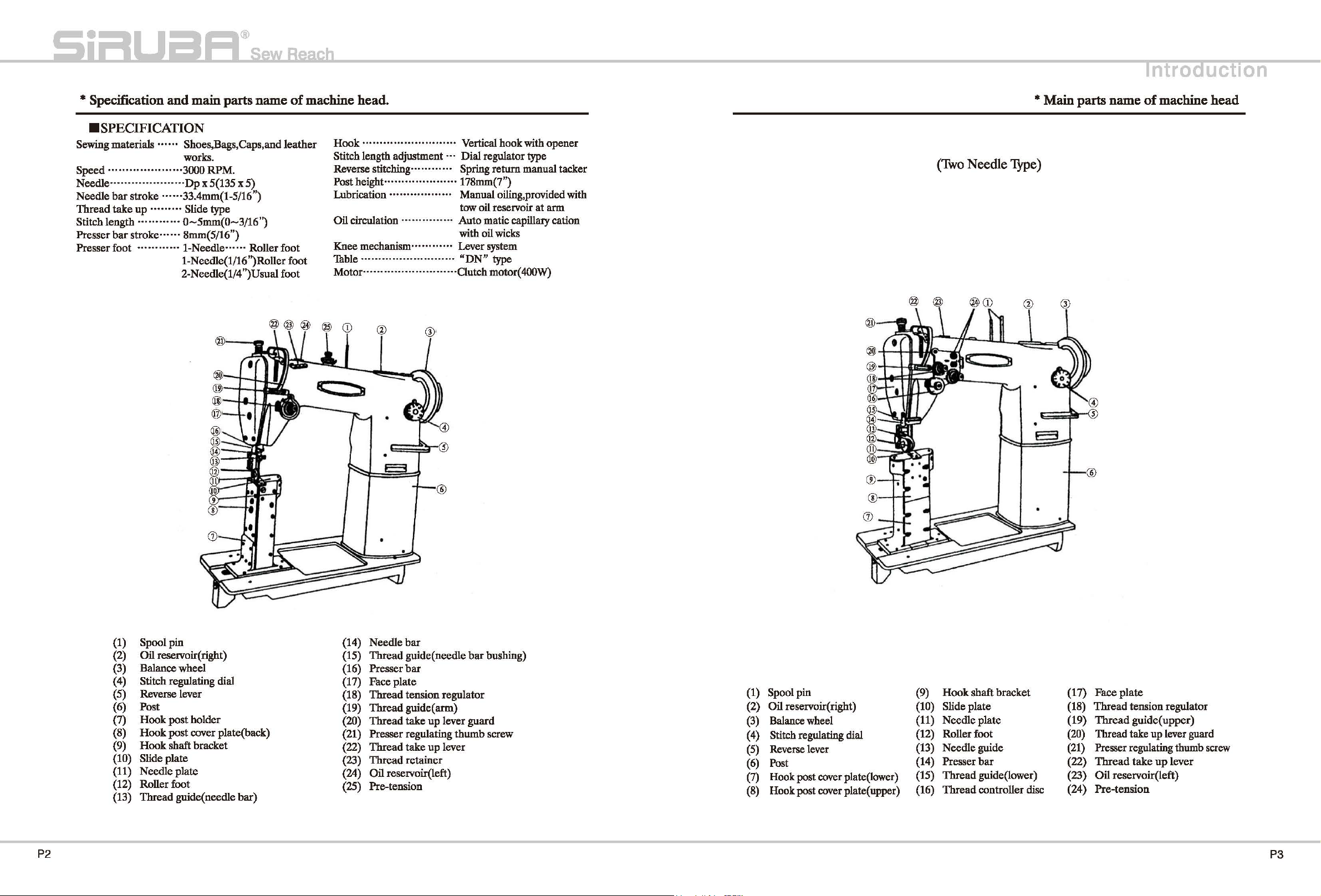
•sPECIFICATION
Sewing materials • .. ·
Speed · ...................
Need1e·······
Needle
Thread
Stitch length
Presser
Presser
bar
take
bar
foot
..............
stroke
up • ........
............
stroke····
............
••
Shoes,Bags,Caps,and
works.
· 3000
RPM.
Dp
x 5(135 x
......
33.4mm(1-5/16")
Slide
type
0-5mm(0-3/16")
..
8mm(5/16")
1-Needle
1-Needle(l/16'')Roller foot
2-Needle(1/4")Usual foot
......
5)
Roller
of
machine head.
leather
foot
Hook
...............
Stitch length adjustment · · ·
Reverse
Post height
Lubrication
Oil circulation ·
Knee
Thble
Motor
stitching............
mechanism............
...........................
...........................
··......
....
........... • ... · .....
.................
··
···
... · ....
Vertical
Dial
Spring
178mm(7")
• Manual oiling, provided with
tow oil reservoir
· Auto matic capillary cation
with oil wicks
Lever system
"DN"
Clutch motor( 400W)
hook
with
regulator type
return
manual tacker
at
type
opener
arm
(Two
Needle
* Main parts name
Type)
of
machine head
Spool
(1)
(2)
(3)
(4)
(5)
(6)
(7)
(8)
(9)
(10)
(11)
(12)
(13)
pin
Oil
reservoir( right)
Balance
Stitch regulating dial
Reverse lever
Post
Hook
post
Hook
post
Hook
shaft bracket
Slide
plate
Needle
Roller foot
Thread
wheel
holder
cover plate(back)
plate
guide(
needle
bar)
Needle
(14)
(15)
Thread
{16)
Presser
Faceplate
(17)
{18)
Thread
(19)
Thread
(20)
Thread
(21)
Presser
Thread
(22)
Thread
{23)
(24) Oil reservoir(left)
Pre-tension
(25)
P2
bar
guide( needle
bar
tension
guide(
take
regulating
take
retainer
regulator
arm)
up
lever
up
lever
thumb
bar
bushing)
guard
screw
(1) Spool
(2) Oil reservoir( right)
(3)
(4)
(5) Reverse lever
(6)
(7)
(8)
pin
Balance wheel
Stitch regulating dial
Post
Hook
post cover plate(lower)
Hook
post cover plate( upper)
(9)
Hook
shaft
Slide
(10)
(11)
(12) Roller foot
(13)
(14)
(15)
{16)
plate
Needle
Needle
Presser
Thread
Thread
plate
guide (21) Presser regulating thumb screw
bar
guide(lower) (23)
controller disc
bracket
(17)
(18)
(19)
(20)
(22)
(24)
Face
plate
Thread
Thread
Thread take
Thread
Oil
Pre-tension
tension regulator
guide(
take
reservoir(left)
upper)
up
lever guard
up
lever
P3
Page 4
*
Preparation
I
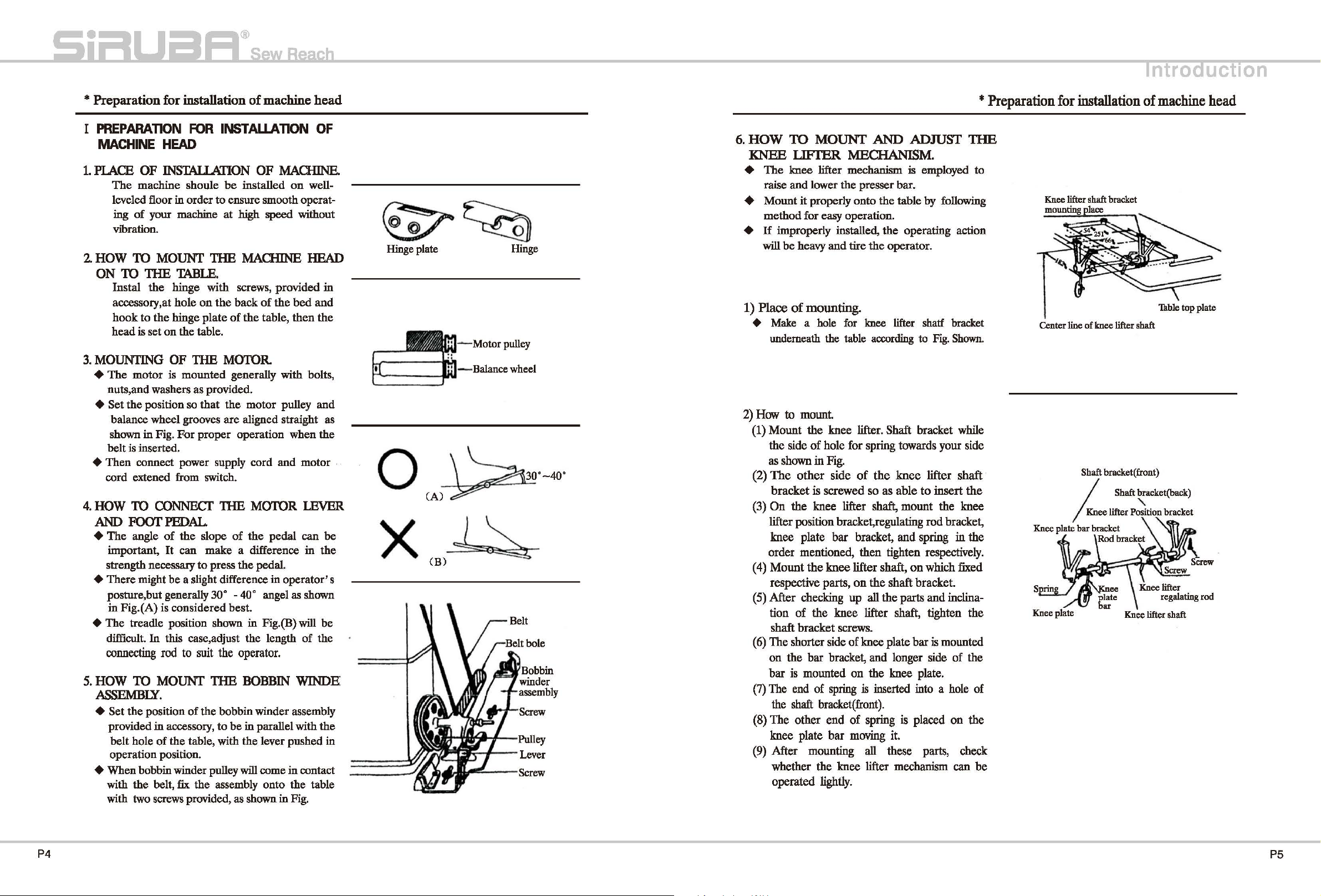
PREPARATION
MACHINE
1.
PlACE
The
leveled floor in order to ensure smooth operat-
ing
vibration.
2.
HOW TO MOUNT
ON
1U
Instal the hinge with screws, provided in
accessory,at hole
hook to the hinge plate
head is set
3.
MOUNTING OF THE MOTOR
+ The motor
nuts,and washers as provided.
for
installation
FOR
of
machine
INSTAUATlON OF
HEAD
OF
INSTAllATION OF MACHINE.
machine shoule
of
your
machine
1HE
TABLE.
on
the table.
is
mounted generally with bolts,
on
be
installed
at
high speed without
1HE
MACHINE HEAD
the
back
of
the
of
the
table, then
on
bed
well-
+ Set the position so that the motor pulley and
balance wheel grooves are aligned straight as
shown in Fig. For proper operation when the
belt
is
inserted.
+ Then connect power supply cord and motor .
cord extened from switch.
4.
HOW TO
AND
+ The angle
important,
strength necessary
CONNECT
FOOT
THE MOTOR
PEDAL.
of
the slope
It
can make a difference in the
to
of
the
pedal can be
press the pedal.
lEVER
+ There might be a slight difference in operator' s
30°
-40°
posture,but generally
in Fig.(A) is considered best.
+ The treadle position shown in Fig. (B)
In
difficult.
connecting rod to suit the operator.
5.
HOW TO MOUNT
this case,adjust the length
1HE
angel as shown
will
of
BOBBIN WINDE
ASSEMBLY.
+ Set the position
provided
belt hole
operation position.
in
of
the bobbin winder assembly
accessory, to be
of
the table, with the lever pushed in
in
parallel with the
+ When bobbin winder pulley will come in contact
with the belt,
with two
fix
the assembly onto the table
screws
provided, as shown
in
Fig.
head
and
the
be
the
Hinge
0
x
plate
Motor
Balance wheel
(A)
Hinge
pulley
(B)~
6.
HOW
KNEE
+
+ Mount it properly onto the table
+
1) Place
+
2)
(1) Mount the knee lifter. Shaft bracket while
(2)
(3)
( 4)
(5) After checking
(
(7)
(8) The other end
(9) After mounting
TO
MOUNf
LIFTER
The
knee lifter mechanism is employed
raise and lower the presser bar.
method for easy operation.
If
improperly installed, the operating action
will
be
heavy
and
of
mounting.
Make a hole
Wldemeath
How
to
the side
as
shown in Fig.
The
bracket
On
the knee lifter
lifter position bracket,regulating rod bracket,
knee plate bar bracket, and spring
order mentioned, then tighten respectively.
Mount
respective parts,
tion
shaft bracket screws.
6)
The shorter side of knee plate bar is mounted
on
the bar bracket, and longer side of the
bar
is
The end of spring
shaft
the
knee plate
whether the knee lifter mechanism can
operated lightly.
the
mount.
of
hole for spring towards your side
other
of
side
is screwed so as able
the knee lifter shaft,
the knee lifter shaft, tighten the
mounted on the knee plate.
bracket(front).
bar
AND
ADJUST
MECHANISM.
by
following
tire the operator.
for
knee lifter shatf bracket
table according to Fig.
of
the
knee
lifter shaft
to
insert
shaft,
mount the knee
on
which fixed
on
the shaft bracket.
up
all the parts and inclina-
is
inserted
of
spring
moving it.
all
into
a hole of
is
placed
these parts, check
* Preparation
1HE
to
Shown.
the
in
the
on
the
be
for
Center line
Knee plate
Knee plate
installation
of
knee lifter shaft
Shaft bracket(front)
of
machine
'Thble
I Shaft bracket(back)
I
Knee
lifter
P~tion
bar
bracket
Rod
bracket
Knee lifter shaft
top
bracket
UCtiOn
head
plate
P4
P5
Page 5
UCtiOn
* Preparation for installation of machine head
3)
Adjustment.
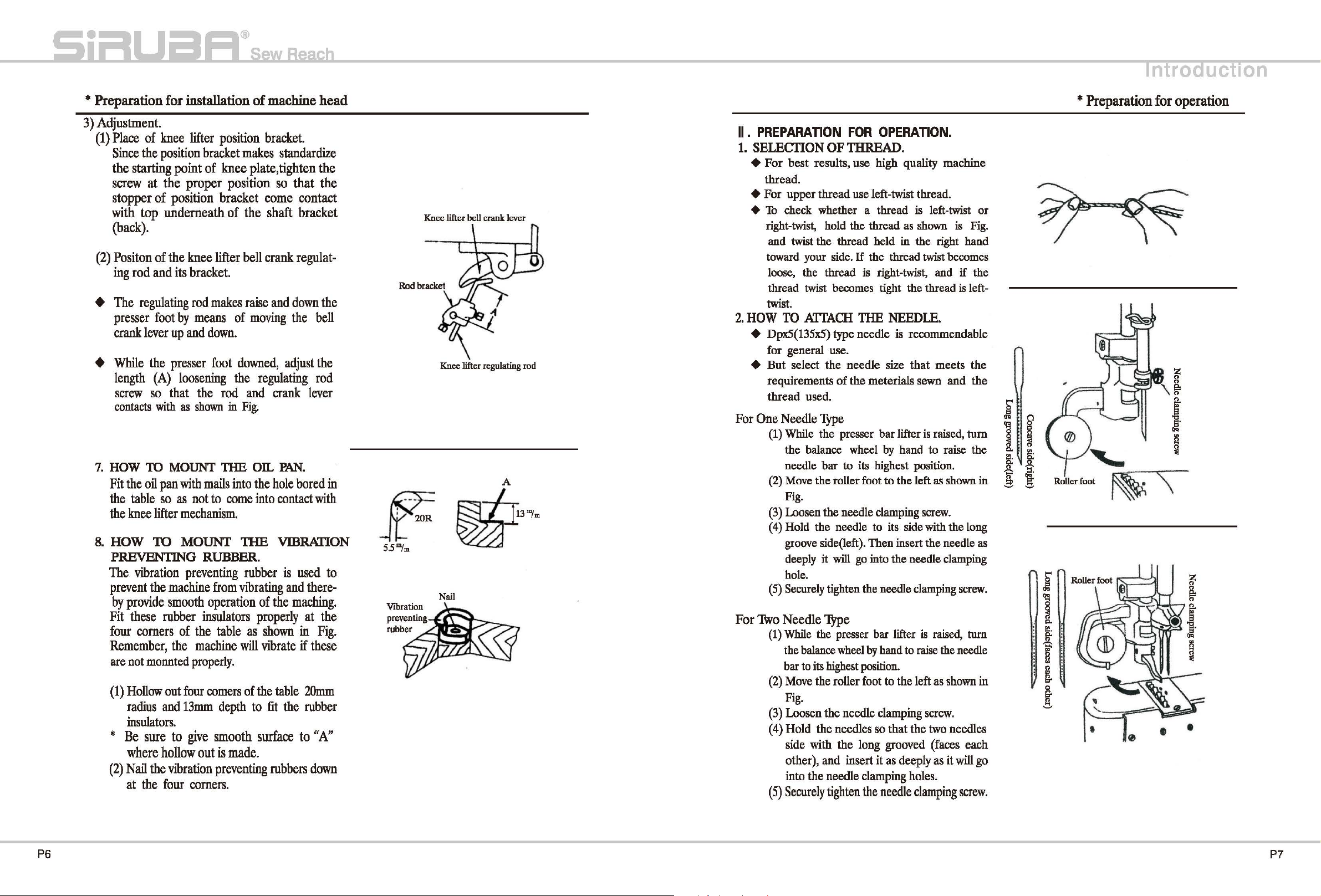
(1)
Place
of
knee
lifter
position
Since
the
position
the starting point of
screw
stopper
with
at
the proper
of
top
underneath
bracket
position
knee
bracket
(back).
(2)
Positon
ing
+
The
presser
crank
+
While
length
screw
contacts with as
7.
HOW TO MOUNT
Fit
the
the
8.
HOW
PREVENTING RUBBER.
The
prevent
by
Fit
four
Remember,
are
(1)
of
rod
and
regulating
foot
lever
the
(A)
so
the
oil
pan
table
so
knee
lifter
TO
vibration
the
provide
these
comers
not
monnted
Hollow
radius
the
knee
its
bracket.
rod
by
means
up
and
presser
loosening
that
the
shown
with
as
not
mechanism.
MOUNT
preventing
machine
smooth
rubber
of
the
the
machine
properly.
out
four
and
13mm
lifter
makes
down.
foot
rod
TilE
mails
to
from
operation
insulators
table
comers
depth
insulators.
*
Be
sure
to
give
smooth
(2)
where
Nail
at
the
the
hollow
out
VIbration
four
comers.
is
preventing
position
of
in
come
made.
bracket.
makes
plate,
come
the
shaft
bell
crank
raise
of
moving
downed,
the
regulating
and
Fig.
OIL
into
the
into
1HE
rubber
vibrating
of
properly
as
shown
will
vibrate
of
the
to
fit
surface
standardize
tighten
so
that
the
the
contact
bracket
regulat-
and
down
the
the
bell
adjust
the
rod
crank
hole
the
table
rubbers
lever
PAN.
bored
in
contact
VIBRATION
is
and
with
used
there-
to
maching.
at
the
in
Fig
if
these
20mm
the
rubber
to
".A:'
down
.
Knee lifter bell crank lever
Knee lifter regulating rod
Nail
II
.
PREPARATION
1.
SELECTION
+
For
best
results,
thread.
+
For
upper
+
To
check whether a thread is left-twist
right-twist, hold the thread as shown is Fig.
and twist the thread held
toward your side.
loose, the thread is right-twist, and
thread twist becomes tight the thread is left-
twist.
2.
HOW
TO
ATTACH
FOR
OPERATION.
OF
THREAD.
use
high quality machine
thread use left-twist thread.
in
the
right hand
If
the thread twist becomes
THE
NEEDLE.
+ Dpx5(135x5) type needle is recommendable
for general use.
+
But
For
For
One
Two
select
requirements
thread
Needle
(1) While the presser bar lifter is raised,
the balance wheel by hand to raise the
needle
(2) Move the roller foot
Fig.
(3)
Loosen the needle clamping screw.
( 4) Hold
groove side(left). Then insert the needle as
deeply it will go into the needle clamping
hole.
(5)
Securely tighten the needle clamping screw.
Needle
(1)
While the presser bar lifter
the balance wheel
bar to its highest position.
(2)
Move the roller foot to
Fig.
(3) Loosen
Hold
( 4)
side
other),
into
(5)
Securely
the
used.
needle
of
the
size
that
meterials sewn
Type
bar
to its highest position.
to
the left as shown in
the
needle to its side with the long
Type
is
by
hand to raise the needle
the
left as shown in
the
needle clamping screw.
the
needles so
with
the
and
insert
the
needle clamping holes.
tighten
that
the
long grooved (faces each
it
as
deeply
the
needle
clamping
meets
and
raised, turn
two needles
as
it
or
if
the
the
the
turn
will
go
screw.
i
l
~
!
~
~
('>
"'
g:
~
c
* Preparation
"'-..
Roller foot
for
operation
~--=~
-
.---.\~
P6
P7
Page 6
UCtiOn
* Preparation
*
When
loops
skipping
these
condition
needle
would
direction.
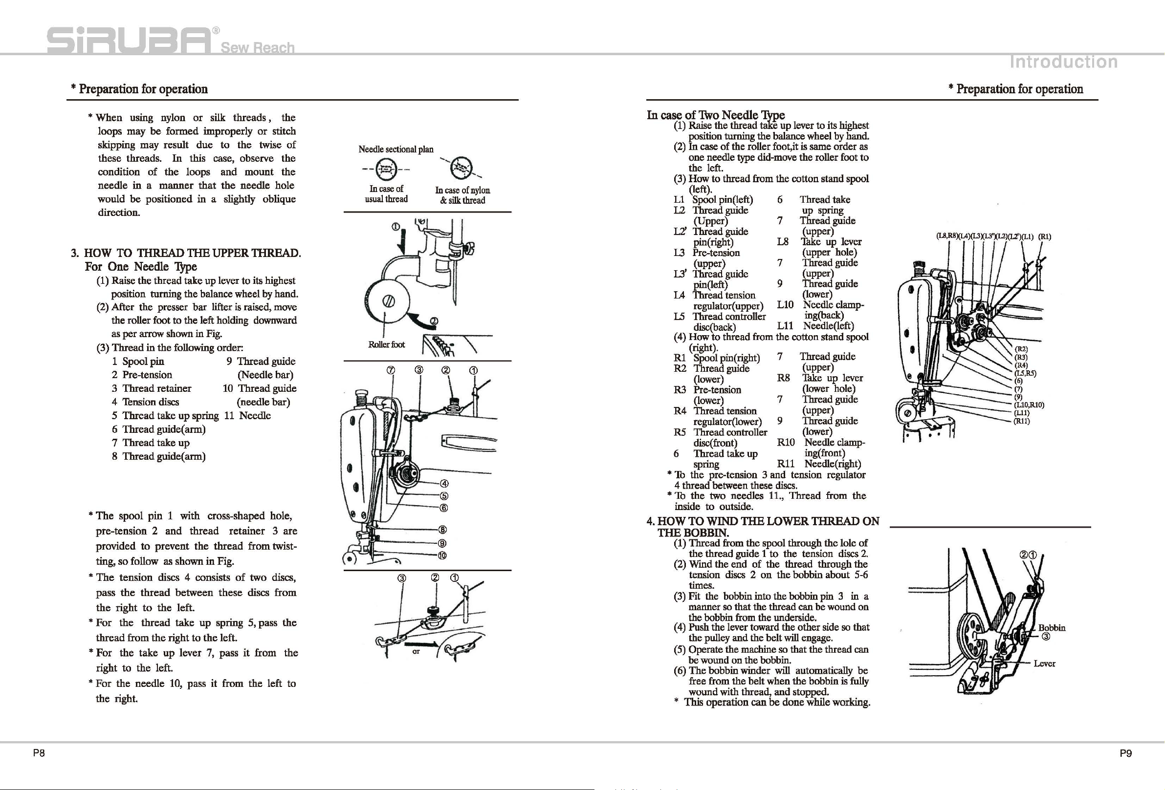
3.
HOW TO THREAD
For
One
(1) Raise
position turning
(2) After
the
as
(3)
Thread
for
using nylon
may
may
threads.
in a manner
be
positioned
Needle
the
the
roller foot
per
arrow shown
in
1
Spool
be
of
thread
pin
2 Pre-tension (Needle
3
Thread
4 Tension discs
5
Thread
6
Thread
7
Thread
8
Thread
*The
*
*
*For
*
spool
pin 1 with
pre-tension 2 and
provided
ting,
The
pass
the
For
thread
right
For
the
so
follow
tension
the
right
the
from
the
to
the
the
needle
right.
to
thread
to
thread
the
take
operation
or
silk
formed
result
In
the
improperly
due
to
this case,
loops
TilE
and
that
in
a slightly
UPPER THREAD.
'!YPe
take
up lever
the
balance wheel by hand.
presser
the
retainer
take
guide( arm)
take
guide( arm)
prevent
as
discs 4 consists
the
up
left.
bar
lifter is raised, move
to
the
left holding downward
in
Fig.
following order:
up
spring
up
cross-shaped
thread
the
thread
shown
between
take
right
10, pass
left.
up
to
the
lever 7,
in
spring
it
Fig.
these
left.
pass
threads , the
or
stitch
the
twise
observe
mount
the
needle
to
9
Thread
10
Thread
(needle
11
Needle
retainer 3 are
of
it
from
hole
oblique
its highest
guide
bar)
guide
bar)
hole,
from
twist-
two
discs,
discs
from
5,
pass
from
the
left
of
the
the
the
the
to
Needle
sectional
-- --
§
Incase of
usual
thread
_plan
.
In
&
te===-=
!'ifi"-
--
-
-®
r
--
~~~:;:;-----@)
--®
case
silk
of
nylon
thread
In
case
of
1\vo
(1) Raise
position turning
In
(2)
one
the
(3) How
(left).
L1
Spool pin(left)
L2 Thread guide
L2'
Thread guide
L3
Pre-tension
L3'
Thread guide
u
Thread tension
Needle
the
thread e up lever
case
of
the
needle type did-move
left.
to
thread
(Upper) 7
pin( right)
(upper)
pin(left)
regulator( upper)
l.5 Thread controller
disc(back) L11 Needle(left)
( 4) How
Rl
R2 Thread guide
R3 Pre-tension
R4
R5 Thread controller
6 Thread take
*
1b
4 thread between these discs.
*
Th
inside
4.
HOW
THE
(1)
(2)
(3) Fit
(4) Push
(5) Operate
(6)
*
to
thread
(right).
Spool pin( right)
(lower)
(lower)
Thread tension
regulator(lower)
disc(
front)
spring
the
pre-tension 3
the
two needles 11.,
to
outside.
TO
WIND
BOBBIN.
Thread
the
Wmd
tension discs 2
times.
manner so that the thread can
the bobbin from
the
be
The
free from
wound with thread,
This
from
thread
the
pulley
wound
operation
guide 1
the
end
bobbin into
the
lever toward
and
the
on
bobbin winder will automatically
the
~e
the
balance wheel by hand.
roller foot,it is same order
from
the
6
L8 Thke
to
its highest
as
the
roller foot
cotton stand spool
Thread
up
spring
Thread
(upper)
up
(upper hole)
to
take
guide
lever
7 Thread guide
(upper)
9 Thread guide
(lower)
Needle clamp-
LlO
ing(back)
from
the
cotton stand spool
7
Thread
R8
(upper)
Thk.e
(lower hole)
guide
up
lever
7 Thread guide
(upper)
Thread guide
9
(lower)
R10 Needle clamp-
up
and
THE
WWER
the
spool through
to
of
the
on
the
the
underside.
the
belt
machine so that the thread can
the
bobbin.
belt
when
and
can be
ing(front)
R11 Needle(right)
tension regulator
Thread
from
the
THREAD
the
lole
the
tension discs
thread
the
the
will engage.
done
through
bobbin
bobbin pin 3 in a
be
other side so
the
bobbin is fully
stopped.
while working.
the
about
5-6
wound on
that
ON
of
2.
be
•
*
Preparation
for
(R2)
(R3)
(R4)
(LS,RS)
(6)
(7)
(9)
(LlO,RlO)
(Lll)
{Rll)
operation
P8
pg
Page 7
*
Preparation
5.
HOW
TO
ADJUST
for
operation
THE
BOBBIN
WINDER
ASSEMBLY.
+
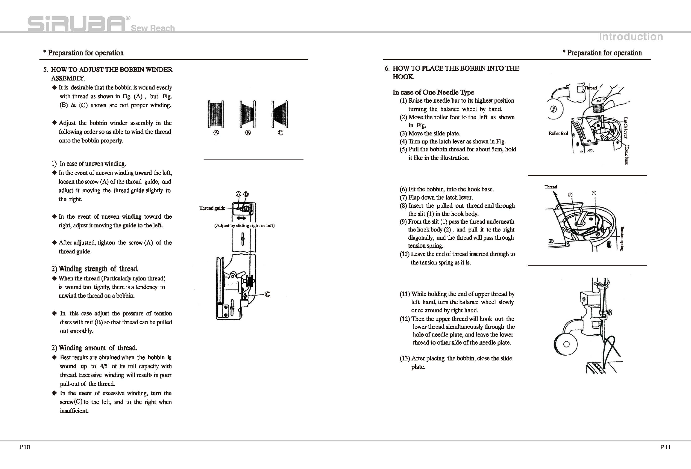
It
is desirable that
with thread as shown in Fig. (A) ,
(B) & (C) shown are not proper winding.
+ Adjust the bobbin winder assembly in the
following
onto
1)
In
+
In
the event
loosen the screw (A) of the thread guide, and
adiust it moving the thread guide slightly to
the right.
+
In
right, adjust it moving the guide
+After
thread guide.
2)
Winding
+ When the thread (Particularly nylon thread)
is
wound too tightly, there
unwind the thread on a bobbin.
+ In this case adjust the pressure
discs with nut
out smoothly.
2)
Winding
order
the
bobbin properly.
case
of
uneven
the event
adjusted, tighten the screw (A)
strength
amount
the
bobbin
so as able to wind
is
wound evenly
but
the
winding.
of
uneven winding toward the left,
of
uneven winding toward
to
the left.
of
thread.
is
a tendency to
of
(B)
so
that
of
thread.
thread can
be
+ Best results are obtained when the bobbin is
wound up to
thread. Excessive winding
pull-out
+ In the event of excessive winding,
screw(C) to the
insufficient.
of
4/5
the thread.
left, and
of its
full
capacity with
will results in poor
to
the right when
tum
Fig.
thread
the
of
the
tension
pulled
the
® ©
®®
-Mphlo~
(Adjust
by
sliding right
or
left)
6.
HOW
TO
PLACE
THE
BOBBIN INTO
HOOK.
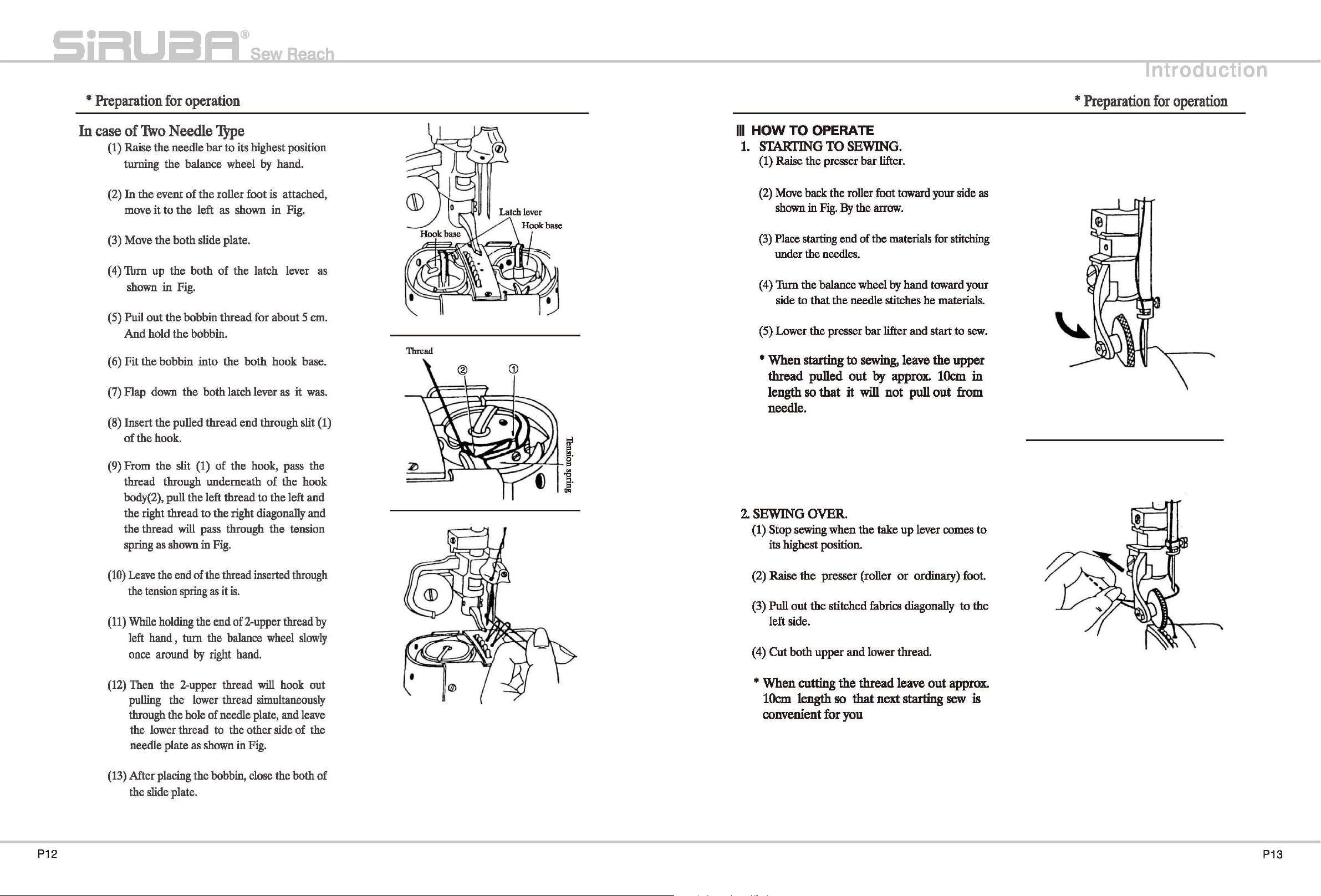
In
case of One Needle
(1) Raise the needle
the
turning
(2) Move
in
Fig.
(3) Move
( 4) Turn
5)
(
( 6) Fit
Puil
it
like in
up
the
the
(7) Flap down
(8) Insert the pulled out thread end through
the slit (1) in
(9) From the slit
the hook body (2) , and pull it to the right
diagonally, and the thread
tension spring.
(10) Leave the end of thread inserted through to
the tension spring
(11) While holding the end
left hand,
once around by right hand.
(12) Then the upper thread will hook
lower thread simultaneously through the
hole
thread to other side
(13) After placing the bobbin, close the slide
plate.
balance wheel
the
roller foot to the left as shown
the
slide plate.
the
latch lever as shown in Fig.
bobbin thread for about Scm, hold
the
illustration.
bobbin, into
the
the
(1)
tum
of
needle plate, and leave
JYpe
bar
to its highest position
by
the
hook base.
latch lever.
hook body.
pass the thread underneath
will pass through
as
it
is.
of
upper thread by
the balance wheel slowly
of
the needle plate.
hand.
out
the
lower
THE
the
Thread
*
Preparation
for
operation
UCtiOn
P10
P11
Page 8
*
Preparation
In
case
of
(1) Raise
turning the balance wheel
1\vo
the
for
operation
Needle
needle bar
'JYpe
to
its highest position
by
hand.
Ill
HOW
1.
TO
OPERATE
STARTING
(1) Raise the presser bar lifter.
TO SEWING.
*
Preparation
for
operation
UCtiOn
(2)
In
the event
move
(3) Move the
(
4)
Thrn
shown
( 5) Puil
(6) Fit
(7) Flap down
(8) Insert the pulled thread end through slit (1)
(9) From the slit (1) of the hook, pass the
out
And
hold
the
of
the hook.
thread through underneath
body(2), pull the left thread to the left and
the right thread
the thread
spring as shown in
of
the
roller foot is attached,
it
to
the
left as shown in Fig.
both
slide plate.
up
the both
in
Fig.
the
bobbin thread for about 5 em.
the
bobbin into
the
will
of
the latch lever
bobbin.
the
both hook base.
both latch lever
to
the right diagonally and
pass through the tension
Fig.
as
of
the hook
it
as
was.
Thread
(2) Move back the roller foot toward
shown
in
Fig.
By the
(3) Place starting end of the materials for stitching
under the needles.
Thm
the
( 4)
side
(5) Lower the presser
balance wheel
to that
the
* When starting to
thread pulled out
length
so
that it will not pull out
arrow.
by
needle stitches
bar
lifter and start
sewing,
by
approx.
your side
hand toward your
he
materials.
leave the upper
10cm
needle.
2.
SEWING OVER.
(1) Stop sewing when
its highest position.
the
take
up
lever comes
to
sew.
in
from
as
to
(10)
Leave the end of the thread inserted through
P1
2
the tension spring
(11)
While holding the end of 2-upper thread
left hand , turn the balance wheel
once around
(12)
Then the 2-upper thread will hook out
pulling the lower thread simultaneously
through the hole
the lower thread to the other side of the
needle plate as shown in Fig.
(13) After placing the bobbin, close the both
the slide plate.
as
it
is.
by
right hand.
of
needle plate, and leave
by
slowly
of
(2)
Raise
the
(3)
Pull
left side.
(4)
Cut
presser (roller
out
the stitched fabrics diagonally
both upper and lower thread.
or
ordinary) foot.
to
the
* When cutting the thread leave out approx.
10cm
convenient for you
length
so
that next starting
sew
is
P13
Page 9
*
Stitching
fV.
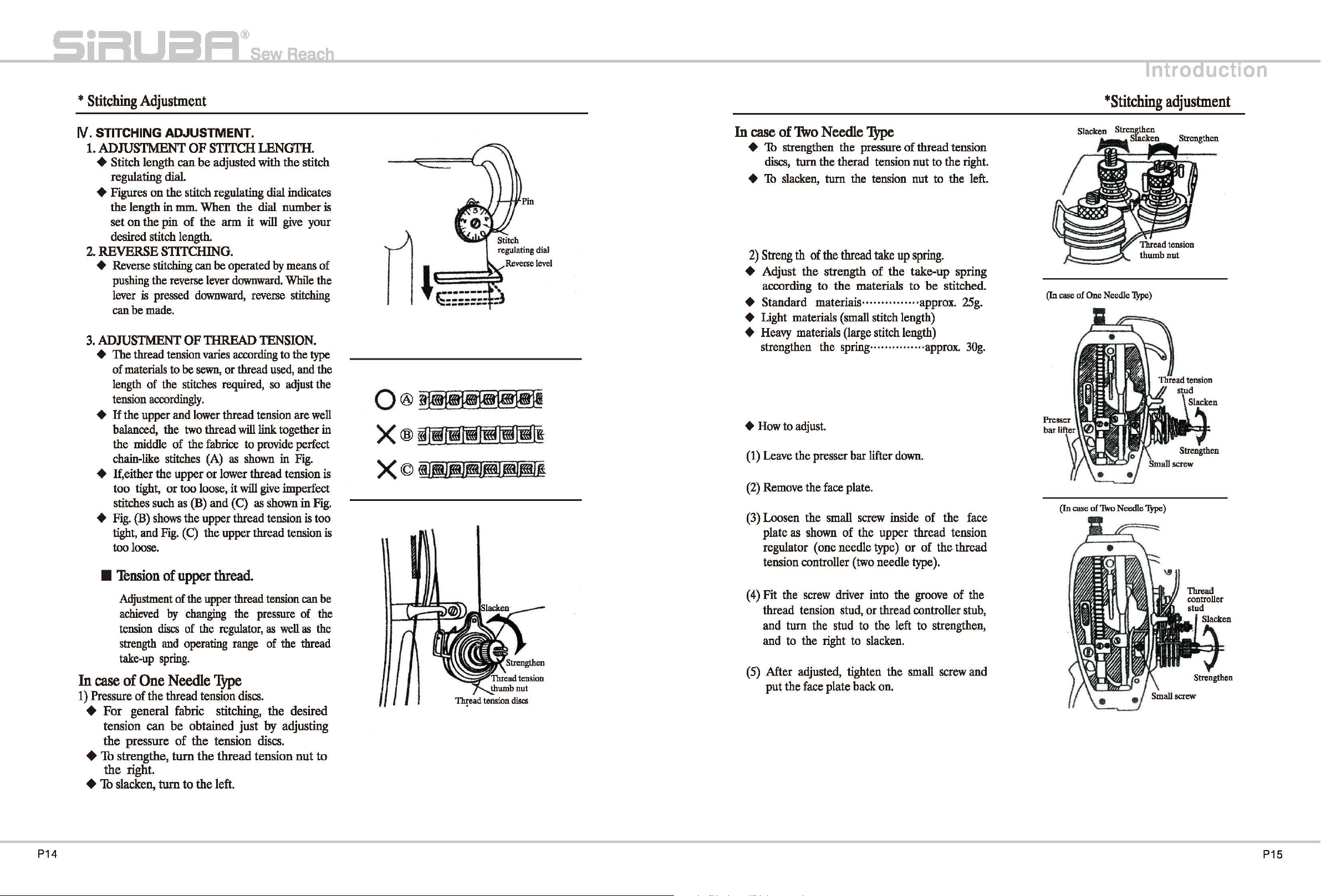
STITCHING ADJUSTMENT.
1.
ADJUSTMENT OF STITCH LENGTII.
+ Stitch length can
Adjustment
regulating
dial.
be
adjusted with the stitch
+ Figures on the stitch regulating dial indicates
mm.
the length in
set
on
the pin of the
desired stitch length.
2.
REVERSE STITCHING.
+
Reverse
pushing
lever
can
3.
ADJUSTMENT
+ The thread
of
length
tension
stitching
the
is
pressed
be
made.
materials
of
accordingly.
tension
the
+ If the upper and
balanced, the
the middle of the
chain-like
stitches
When the dial number
arm
it
can
be
operated
reverse
lever
downward.
downward,
reverse
OF THREAD
varies
according
to
be
sewn,
or thread
stitches
two
required,
lower
thread tension are
thread will link together
fabrice
(A)
as
to
shown
will
give
by
means
While
stitching
TENSION.
to
the
used,
and the
so
adjust
provide
in
perfect
Fig.
+ If,either the upper or lower thread tension
too tight,
stitches
+
Fig.
tight,
too
loose.
•
'Thnsion
Adjustment
achieved
tension
strength
take-up
In
case
of
1)
Pressure of the thread tension
+ For general fabric stitching, the desired
tension can
the pressure
+ Th strengthe,
the right.
+
Th
slacken, turn to the left.
such
(B)
shows
and
One
or
too loose, it
as
(B)
the upper thread tension
Fig.
(C)
the upper thread tension
of upper
of the
upper
by
changing
discs
of the
and
operating
spring.
Needle
will
and (C)
thread.
thread
the
regulator,
range
"IYPe
discs.
be
obtained just
of
the tension
turn
the thread tension
give
imperfect
as
shown
tension
pressure
as
well
of
the
by
adjusting
discs.
in
is
can
of
as
thread
nut
is
your
of
the
type
the
well
in
is
Fig.
too
is
be
the
the
to
0®~
X®
X©
~tmliftm419Im~
@J@l@l®!®®i®i
In
case
of
1\vo
Needle
'l.YPe
+ 1b strengthen the pressure of thread tension
discs,
turn
the therad tension nut to the right
+ 1b
+ Adjust the strength
slacken,
2)
Streng
according to the materials to be stitched.
th
of
turn
the
the tension nut to the
thread take
up
spring.
of
the take-up spring
+ Standard materiais ............... approx.
+ Light materials
+
Heavy
strengthen the
+
How
(1)
(2)
(3)
plate
(
4)
thread tension stud, or thread controller
and
and
(5)
materials (large stitch length)
to
adjust.
Leave
the presser bar lifter
Remove
Loosen the small
regulator (one needle
tension controller
Fit the
After adjusted, tighten the small
put the
the
as
shown
screw
turn the
to
the right
face
(small
stitch length)
spring
...............
face
plate.
screw
inside of the face
of the upper thread tension
type)
(two
needle type).
driver
stud
plate back
into the
to the left to strengthen,
to
slacken.
on.
approx.
down.
or of the thread
groove
screw
of the
left.
25g.
30g.
stub,
and
*Stitching
(In case of One Needle
(In case of
'1\vo
Needle
UCtiOn
adjustment
lYJ>e)
'JYpe)
P14
P15
Page 10

*
Stitching
Adjustment
*Stitching
UCtiOn
adjustment
3) Operating range of the thread take
+ In order to obtain proper
it
is
necessary
up
spring
range of the take-up
to adjust the strength of the take
as
well
working
as
change the operating
spring.
+ The operating range can be measured
take-up
when
tension spring
it
e In
....
e In
increase the operating range
..
e In
decrease the operating range
......
+How
(1)
Lower
(2)
Loosen the thread tension regulator set
(3)
Fit the
tension
right
(
4)
Thrn the stud to the left to large the operating
(5)
After adjusted, tighten the
+
How
(1)
Loosen the thread controller set
(2)
Fit the
thread controller
the
(3)
Turn
range.
(4)
After adjusted, tighten the
lever
is
the upper thread
moves
is
considered
case
of standand (general
ooapprox.
case
of
light
8mm(5/16
(small
at the
as
highest
within the
standard.
')
stitch
is
pulled, and the
winth
fabrics)
length) materials,
slightly
..
ooapprox.
case
of
heavy
8mm(5/16")
or
up
(large stitch length) materials.
slightly
approx,
8mm(5/16")
or
less
to adjustment (One Needle
the presser bar lifter.
screw
driver
regulator
to
small
the operating
rang.
to adjust
right
screw
to
small
('Ibw
driver
the stud to the left to rarge the operating
into
the
stud;
and
turn
range.
screw.
Needle
'!YPe)
into the
stud,
and
the operating
screw.
turn
up
spring.
condition,
when
the
position, and
of 8mm,
materials.
.. ·· .. ·· .. ··
........ .
'!YPe)
screw
groove
the stud to the
groove
rang.
of the
screw.
of the
the stud to
• Thnslon of
There
tension,
when
slighe
(1)
(2)
(3)
(
4)
4.
ADJUSTMENT
AND
RIALS .
The
feed
materials
the materials to
+ In
case
be
damaged
the pressure of presser on materials
+ In case of
uniforme stitching
.
properly
In
......
In
·..............
In
......
* The height
the feed dog
from
balance wheel
1)
Adjustment
(1)
Lay down the machine bed toward the
other side.
(2)
Remove
(3)
'Ibm the balance wheel
when
position from the surface of needle plate.
4)
Loosen the
(
crank.
(5)
Adjust the feed
moving
back and forth
Fig.
(6)
After adjusted, tighten the screw of feed
lifting rock shaft.
lower
is
virtually
except
adjustment
'Ibm
when
to
its
Move
thread
Fit
the
hook
tension
thread
Turn
thread tension.
PRESSURE
dog
must
of
if
or
case of light materials ... .
·........ approx.
case of general fabrics·
case of
·........ approx.
the
surface
the feed
thread.
no
need
to
adjust
for
special
kind
will
be
necessary
the
balance
the
thread
lowest
the
tension
screw
shaft
screw
tension.
the
screw
height and pressure of presser on
be properly adjusted according to
be
light
the
heavy
the pressure of presser
heavy
of
feet dog
is
raised to its highest position
by
of
the gear
the
wheel
take-up
position.
slide
plate
screw
of the
driver
into
bradket
screw
as
shown
to the
right
to the left to
OF
FEED
OF
PRESSER
sewn.
materials:
feed
dog
is
raised
materials: It will not make
if
the feed dog
0.8mm
approx.
of
hand.
feed
feed
l.Omm.
materials .................. · ..
1.2mm.
is
needle plate turning the
dog
box.
dog
is
raised to its highest
of feed lifting rock shaft
dog
to
lifting
as
per
an
the
lower
thread
of
fabrics
or
thresd,
by
hand,
and
lever
comes
down
so
that
you
find
hook
base.
the
hole
(A)
of
in
Fig.
Thm
to
strengthen
weaken
DOG
The material
excessively
is
is
................
........
measured when
the
HEIGHT
ON
MATE-
too
strong.
not raised
is
too
weak.
in height
· ............
in height
in height
height.
by
hand and stop
the desired
rock
arrow
height
shaft crank
shown
stop
the
the
the
the
may
or
.. ..
..
in
Thread tension spring
Thread
tension
screw
~~
~:
Feed lifting
Screw shaft crank
!o.smm
@I
1.2mm
21?
rock
P1
6
P17
Page 11

*
Stitching
Adjustment
*
Stitching
UCtiOn
adjustment
2)
Adjustment of pressure of presser
(1)
Thrn the presser regulating
(2)
5.
PROPER
AND
Place
scribed
in the
shock,
new a one.
1)
How
(1)
(2)
the right
presser
Turn
pressure of presser
E\NEEDLE.
and
below
hook,
or other
to
Turn
when
to
its
Remove
bobbin.
to
strengthen the pressure of
foot.
the screw to the left to loosen the
foot.
TIMING
adjust
in
or
when
causes,
remove
the balance
the thread take
lowest
the
BE1WEEN
the hook
case
of the thread
its
position
or
the
position.
slide
in
the
when
it
hook
wheel
up
plate, then take out the
thumb
THE
condition
gets
entangled
is
changed
is
replaced
by
hand and stop
lever
comes
foot.
screw
HOOK
de-
due
with
down
to
to
2) How
to
place
(1) Place the hook in backward order from
removing procedure.
(2)
When
place
taken out.
(3)
When
base
cap
Fig.
And
the hook
side.
(
4)
When placing the needle plate, place the
needle plate adjusting the hook base
the tip of hook base
finger of the needle plate
the
hook:
placing
it at the
inserting
the hook
same
the
hook
turning it to the left
fit
the hook
body
on
the inside of the other
body,
remember to
position
base
hold
base
brim
fits
into the hook
as
shown
as
the hook
as
shown
into
in Fig.
it
so
was
slot
that
in
of
Hook
base
brim
(3)
Remove
(4)
Remove
case
cover
(5)
Remove
remove
(
6)
Loosen
hook
shwon
(7)
Hold the latch lever up turning it
so
(8)
Remove
that it
the needle paate.
the hook
of
two
needle
plate(upper)both the front and
the hook opener
the opener.
the hook
gib
fixed
in
Fig.
that it can
the
can
be taken out.
cover
type,
gib
screw
in
front of the book
be
taken out.
hook
body
plate (front) (In
remove
center set
screw,
and
remove
the hook
back.)
and
then
the
body
as
slightly
screw
so
The
position
As
shown
2.0mm
the hook and
from
in
of
the
Fig.
its
lowest
needle
the
hook and needle:
When
the
needle raised
position of the
should
be
as
follows.
needle,
+ Upper part of the needle hole··················
... · ..
Lower
+
Tip
of hook ........ · ...... At center of needle.
+
Gap
face
of needle····· .... ····· .. ····· by
Adjustment
hook
* Move the roller foot to the left, remove the
needle plate for
by
1.6mm
between tip of hook
of the relative position of the
and
needle
from
can
easy
adjustment.
be
the
and
done
tip
of
lateral
0.05mm.
as
follows:
hook.
is
Lower part ...___,..___._
of
needle
~~~
needle 4
2.0mm.
Raise
by
o.osmm
}
Tip
of
book
(upper
view)
P18
P19
Page 12

*
Stitching
Adjustment
• Adjustment of needle bar position.
Adjust the needle
between
needle hole will
reised by 2.0mm from its lowest position.
(1) Raise the needle
(2) Loosen
(3) Adjust moving the needle
( 4) After adjusting the needle bar position, tighten
the
position turning the balance wheel by hand.
the
through a driver hole(lower)of
that
the tip
1.6mm from the upper
the needle bar connecting stud screw.
• Adjustment
+ Adjust so that the tip
of
needle.
(l)Remove
the needle palte
tip
of
be
needle
of
hook comes
of
tip
bar
timing so
hook and the upper part
1.6mm when
bar
by 2.0mm from its lowest
bar
connecting stud screw
part
of
hook
of
hook comes to the center
the
bar
up
at
the
of
needle hole.
and
slide plate.
that
the gap
the
needle is
face plate.
and
down so
position by
of
(In case
of
One
Needle JYpe)
+
Adjust
lateral
In
adjust it. However, in case
necessary
gauge sizes.
(1) Loosen
(2) Lay down the machine
(3) Remove
( 4) Loosen the hook shaft gear set screws.
(5) Loosen
( 6)Thrn the balance wheel
(7) Thm
(8) Move
(9) After adjusting, tighten the set screws
(10) Place the gear box.
that the
side
case
of
Plate(front and back).
side.
the needle is raised
position.
the
hook
to
the
left, so that the sap between the tip
and lateral side
shaft gear and bracket.
gap
between
of the needle to
1-needle,
to
adjust
the
the
the
hook by hand and bring
the center
there
it
when changing
screws
gear box.
set screws
of
hook shaft bracket
of
needle
the
come
is
virtually
of
of
the hook post cover
head
toward the other
of
hook shaft bracket.
by
hand, and stop when
by 2.0mm from its lowest
needle.
is
0.05mm.
tip
2-needle, it is
to
of hook and
to
0.05mm.
no
need
the
needle
the
tip
the right
of
hook
of
hook
to
of
and
(In case of
Two
*
Needle
_
Stitching
'!YPe)
.-:-~-~
_.-
Hook past cover
plate( upper)
UCtiOn
adjustment
Hook
past cover
set screw.
the
hook
needle.
the
the
(2) Lay down the machine head toward
Side.
(3) Remove the gear box.
( 4) Loosen the two set screws
gears.
Thrn the balance wheel by hand, and stop
( 5)
to
is
the
when the needle
lowest position.
( 6) Thm
(7) After adjusting, tighten
(8) Place
the
hook by hand enabling
hook
to
come
the hook shatf gears.
the
gear box.
of
raised 2.0mm from its
center
of
the
two set screws
other
shaft
tip
of
of
(In case of'IWo Needle
'!YPe)
~
~~of"
------::~-r
~~
~
g
:X:
!'i
0
...
~
I~
setscrew
6.
PROPER
TIMING
BE1WEEN
AND OPENER.
(1) Remove the slide plate.
(2) Turn
(3) Check whether the gap between
(1) In case the gap is too wide
(5)
the
balance wheel by hand, and stop at
the
position where the opener
plate are furthers point apart.
hook base(A)and the opener is approx. 0.2mm
as shown in Fig.
(There is a slight difference according
thread
it fitting the
of
opener adjustable
to the right or left.
to
be used)
screw
driver into a driver hole (B)
the hook shaft bracket, then loosen the
screw
After adjustment, tighten the opener adjustable
Screw.
and
and
or
narrow, adjust
moving
THE
HOOK
the
needle
the
part
the opener
to
of
the
,._..._,_
Opener adjustable
screw
P20
P21
Page 13

*
Stitching
7.
PROPER
DOG
The proper timing of the feed dog and needle
be when the material
tip reach
moment the feed dog begins to sink downward
through the needle plate surface
This adjustment
atl.Omm.
(1) Loosen the arm side cover thumb
(2) Move the side cover
upper side
Adjustment
TIMING
AND
NEEDLE.
to
the needle plate surface, just at the
is
as shown in
BETWEEN
is
fed through and he needle
based on the Feed dog height
to
the right, and open to
Fig.
TIIE
as shown in
screw.
FEED
will
Fig.
is
*
Cleaning
V.
CLEANING
1.
Cleaning.
The teeth
regulator
often covered
operation and uneven stitching. Therefore, clean
as
often
2.
lubrication.
Lubrication
the machine maintenance. With improper lubrication,
excess
shorten the life
lubricate in the order
1)
The
(1) Usual working
(2)
AND
of
feed
discs,
by
as
necessary.
is
one of the
abrasion
number
Continuous
LUBRICATION.
dog,
hook, upper thread tension
and thread controller
dust and lint causing improper
most
important phases of
of
machine paits
of
the machine, Therefore,
as
follows:
of
times for lubrication.
......
at
2-3 times per week.
working,
every
day·
will
.. once
discs
cause to
each
are
day
and
Lubrication
UCtiOn
(3) Loosen the set
( 4) While holding the feed lifting cam
tum
the balance wheel toward your side so
that feeding device
(5)
In
order to
balance wheel toward the other side.
(
6)
After adjustment, tighten the set
feed lifting cam.
2-screws
slow
of the feed lifting cam.
will
be faster.
the feeding device, tum the
screws
by
hand,
of
the
2) Volume
Places o
Place
mn
Place
3)
Places where
Lubricate the
(inside
of
of
lubrication:
""arked
' marked· .. approx. 5-6 drops
marked···approx. 1-2 drops
to
places
face
plate, arm bed)
.. ·approx.
lubricate.
where
arrow
is
Sec
shown
or
in
more
Fig.
P22
P23
Page 14

*
Cleaning
and
lubrication
*
Since
the
lifting crank
worked
working
oil,
it has
to
(if
oil
Dow
the
no
wick
for
the
oils,
oil
effect
connected
right
penetrate
wick
is
to
Dow
with
side
of
hook
oil
fully
not
penetrated with
oil),
Gear
the
shaft is
before
case
feed
(Hook shaft right)
Screw@
Feed Oil wick
liftin
cr:f
1.*1;$~
2.~00"Blf~~
s.WMIHl$~
6.¥1l.*tllfl!~
7
."""FtmJ:.
B.~B:ei*tl$~
9.~$1ll*tllfl!~
"""F~~$~
11.DC1*
ARM BED AND
ITS
ACCESSORIES
THREAD TENSION MECHANISM
NEEDLE BAR AND TAKE-UP LEVER MECHANISM
PARTS OF
UPPER SHAFT AND VERTICAL SHAFT
BACKSTITCH DEVICE
PRESSER FOOT MECHANISM
PARTS OF BOTTOM SHAFT
AND
TOP/BOTTOM
FEEDING
HOOK
MECHANISM
OIL LUBRICATION MECHANISM
GAUGE PARTS
ACCESSORIES
26
28
30
32
34
36
38
40
44
46
48
3. GREASE.
1)
Remove
gear
box
grease
2)
Remove the
shaft,
then
the
fixed
into
the
also
oil
to
holes
gear
grease
hole
screws(A)&(B),
arm and
periodically.
case
of
the left
into
the
hook
gears
of
shaft,
then
side
of
hook
sufficiently
the
1
2.~53UDCf**H
SPECIAL
PARTS
50
P24
P25
Page 15

Series
SiRUBFI
PARTS LIST P717K/P727K
ARM
Subject
BED
AND
ITS
ACCESSORIES
*HBB~
Page
1/2
Date
2013/6/28
SiRUBFI
PARTS LIST
Fig. Part No. Code No.
No.
.f-1:
P717K/P727K
••
Series
Mtt
$
Cl
AA
~
Subject
ARM
BED
AND
ITS
ACCESSORIES
*llffB~
Neme
of
Part
2013/6/28
-!Ita
Amt.rep
P717K
Page
2/2
Date
P727K
3
~
30
20
1 8100101-000 M91101 004
2 8100102-000 M9110B 002
21
8100103-000
3
8100103-001
4
81
001
04-000 MF
5 8100105-000
6
81
001
06-000
7
8100107-000
8
81
001
08-000
15 8100115-000 M9
16 8100116-000
17 8100117-000
18 8100118-000 MF
19 8100119-000
20 8100120-000 MV01AO
21
8100121-000
22 8100122-000 M95001 062
23 8100123-000
24 8100124-000
25 8100125-000
26 8100126-000
27 8100127-000
28 8100128-000
29 8100129-000
30
81
00130-000
31
8100131-000
MF 10AOB30
MF 10AOB30
60AO
326
M9 0915 003
M91107
MQ50A0584
M9 1108
M9 0908 015
MF
MF
M9 0904
M9150B
MQ50AO
M9 1110 002
MV
M9 1180
0901
10AO
60AO
10AO
11EO
002
001
035
186
880
180
011
001
-~
-~
iii~
iii~
jr}ji!9~(
Jj\)
-~
·-
~~-
-~
-~
·-
~-*"
jr}ji!9~(:;t)
~11.i§&l:+f
i§&l:+f
181
JIUJ
·-
~-
*•
m!!«JIC!
m!!«JIC!
-~
181
i§&l:+f(""P~)
-~
181
1§*1
080
i!BK
Screw(for Fig.3)
Screw(for Fig.3) 1 1
plate
Face
Plate For MS-551 0 1 1
Face
Side cover 1 1
Screw(for Fig.4)
Screw(for Fig.7) 1 1
Thread
Set screw(for Fig.19)
Screw(for Fig.1
Screw(for Fig.18)
Spool. pin 1 2
Arm side cover 1 1
3
Thread guide(arm) 1 1
Screw(for
Pin(for Fig.23) 1 4
Name
Arm and bed 1 1
Model plate 1
Model plade
Set screw(for Fig.902) 1
Thred guide(under arm) 1 1
Screw(for Fig.28)
Thread guide 1
Rubber cork 2 2
take-up
hole thread retainer 1
Fig.20)
plate 1 2
cover 1 1
B)
3 3
1 1
1 1
1
1 1
1 1
1 1
1 1
1
P26
P27
Page 16

Series
Sii=IUBFI
PARTS LIST P717K/P727K
UPPER
THREAD
Subject
TENSION
REGULATOR
MECHANISM
UJeUBB~
Page
1/2
l---=----1
Date
2013/6/28
Sii=IUBFI
PARTS LIST
Fig.
No.
Part No.
V#Mill
Series
P717K/P727K
Code
No.
MM
ms
UPPER
1::::1
AA
THREAD
~
Subject
TENSION
REGULATOR
MECHANISM
Page
2/2
Date
illifiilffR~
2013/6/28
mta
Amt.rep
P717K
Neme
of
Part
P7271<
903
t
27
P717K
~
11
~
8
25
\
~
i
7
16
45 44 43 42
t
26
---0
6
5
4
41
1tr
22
40 39
902
28
38
37
36
35
3
I
902 81003902-000 MV
903 81003903-
000
1
8100301-000
2
8100302-001
3
4
8100303-000
8100304-000
5
8100305-000
6
8100306-000
7
8100307-000
8
8100308-000
9
10 8100309-000
11
8100310-000
8100311-000
12
13
8100312-000
14
8100313-000
15
8100314-000
8100315-000
16
17
8100316-000
8100317-000
18
19
8100318-000
20 8100319-000
21
8100320-000
8100321-000
22
23
8100322-000
8100323-000
25
8100325-000
26
27
8100326-000
8100327-000
28
35 8100328-000
36 8100335-000 MF
37
8100336-000 MF
38 8100337-000
39 8100338-000
40 8100339-000 MF
41
8100340-000
42 8100341-000 MV
43
8100342-000 M9 0212 060
44
8100343-000
MV0230210
M91604
MV01A0802
MV01A0558
MV01A0553
MV01A0709
01EO
210
046
10A0245
10A0556
10A0555
01AO
187
~ttl!(¥jf)
~ttll(!fjf)
...
illAtMta
··~·
~·-·
•••
JliiWMf
...
...
~
ltMtl'f
ltfll#f
...
li
.*-&
••
·-
...
J:U1Jii
JUIU~
j8,it11.11
l8.M1LIIIII
liAt
••
j8,fil1(.j1;J.
...
fl$]!1
••
••
IIM#f
-~31:
...
·-
~ttJttiHIICI
~tt~•
~ttit
~tt-J:t
~tt~J:t
~ttit
~tt!lf.t
~ty:ttg••
~ttU
~ttmHJ:t
Thread tension regulator Assy
Thread tension regulator Assy 1
Nut 2 2
Spring Guide Assy 1
Tensin Spring 1
Thread Take-up Spring
Tension Disc 2 4
Thread Tension Stud 1 1
Screw 1 1
Thread Tension Regulator Bushing 1
Tension Releas Pin 1
Tension Releas Pin 1 1
Tension Releas Plate 1 1
Screw 2 2
Tension Release Spring 1 1
Nut 1
Upper Thread Tension Plate
Thread Tension Stud 1 2
Thread Guide Bracket 1 2
Thread Guida Disc 1 2
Thread Guide Spring 1
Thread Guide Cap
Screw 1 2
Tension disc Washer 1 2
Screw 1 1
Tension Ralaasihg Pin 1 1
Bushing 1
Screw
Screw 1
Thread tension regulating thumb 1
nut 1
Thread tension spring 1
Thread tension releasing disc 1
Tension regulator stop plate
Tension regulator bracket
Tension disc 1
Thread tension stud 1
Thread take-up spring 1
Thread tension releasing pin 1
1
1 1
1 1
1
1
1
2
2
2
1
1
1
2
2
1
1
P28
P29
Page 17

Series
SiRUBFI
PARTS LIST P717K/P727K
n-
•
87-
Q
r.,=
-90
109
108 107
106
NEEDLE
101
Subject
BAR
AND
TAKE-UP
tt•BB~
LEVER
MECHANISM
Page
1/2
Date
2013/6/28
SiRUBFI
PARTS LIST
Fig.
No.
75 8100575-000 MF
76
77
78
79 8100579-000
80
81
82
83 8100583-000 M9 0909 003
84 8100584-000
85
86
87
88
89
90 8100590-000
91
92 8100592-000 MN
93
94 8100594-000
95
96
97
98 8100598-000 M9
99
100 81005100--000 MF 60A2 740
101
102
103 81005103--000 MQ
104 81005104-000
105
106
107 81005107--000 MF
108 81005108--000 MF
109 81005109-000 M9 1110 002
Part
¥#!iii
81
00576--000 MF 10A2 740
8100577-000 M9 1102
8100578-000 MF 60AO
8100580-000
8100581-000 MN
8100582-000 MF
8100585-000
81
00586--000 MF
8100587-000 MF
8100588-000 M9 0802 003
8100589-000 MF 10A2
8100591-000 M9 1516
8100593-000
8100595-000
81
00596--000 MN
8100597-000
8100599-000 M9 1513
81005101--000 M9
81
0051
81
0051
81
0051
P717K/P727K
No.
Code
~-
60AO
MF 10E2 148
MN
10A1
10A1
10AO
MV
01AO
MV
02AO
10AO
10A1
10AO
MP
0080
MV
02AO
MN
10AO
10AO
MQ
50AO
1601
1606001
02--000 MF 20A2 352
50AO
MV
01AO
05--000
06--000 M9
MF 20A2 352
1801
10AO
10AO
Series
No.
742
001
663
500
740
665
660
660
664
181
181
001
587
582
582
588
387
661
001
001
232
383
002
662
325
Subject
NEEDLE
BAR
AND
TAKE-UP
ttttffBf9
c
$
lUI
~
Ull
$E@;~Jt
-~
ttft1Jf(fal)
flb,f_,
....
fib~
tt~a
-~
~~~~
~ttit*
ttft1l(l')
¥ttnld
ttft!U
-~
tt
Gal
¥tt~tl¥
~"·
~tt~tl¥
li*T~
~"-·
ttH:f&f
G*lill.
$E@;ft~J:t
fib~
G*&\M
am
UIJ.Ctr:)
~~~~~
G*l
G*l
08
tt~
Needie bar upper bushing cap 1 1
Needie bar upper bushing cap
Set screw(for Fig. 78) 2 2
Needle bar bushing( upper) 1 1
Oil wick 2 2
Plastic plug(for Fig. 84.85) 1 1
Felt 1 1
Needle bar connecting stud
Screw(for Fig. 82)
Needle bar 1
Needle bar 1
Needle bar bushing(under) 1 1
Thread guide 1
Needle clamp screw 1
Thread guide 1
Needle 1 2
Set screw(for Fig .92) 1 1
Take-up
Take-up
Takw-up
Take-up
Crank pin 1 1
Needel bar connecting crank rod
Set screw(for
Sat scraw(for
Fait 2 2
Set screw(for
Upper shaft collar 1 1
Upper shaft bushing(lett) 1 1
Crank 1 1
Sat scraw(for
Sat scraw(for
Needle bar connecting link guide
Square block(for Fig.82)
Screw(for Fig
-~
Neme
laver support stud
laver
lever
slide block
Fig.1
Fig.1
Fig.1
Fig.1
Fig.1
.1
LEVER
MECHANISM
of
Part
feH
04) 1 1
03) 3 3
02) 2 2
04) 1 1
04)
07)
P717K
Page
2/2
Date
2013/6/28
ill~
Amt.rep
P727K
1 1
1 1
1 1
1 1
1
1
1 1
1 1
1 1
1 1
1 1
2 2
P30
P31
Page 18

Series
Sii=IUBFI
PARTS LIST P717K/P727K
·~rn
.... QJ
PARTS
Subject
OF
UPPER
SHAFT
AND
VERTICAL
...tIll
lill!diiJ;t
904
~+-------------1~
'
\---------
1,..-------
-------142
SHAFT
2013/6/28
115
141
Page
1/2
Date
906
Series
Sii=IUBFI
PARTS LIST P717K/P727K
Fig. Part No. Code No.
No.
115
116
117
118
119
120-A 81007120-00A
120-B 81007120-008
121
122
123
124
125
126
904
127
127-1 81007127-001
128
129
130
131
132
133
134
135
136
905
137
138
139
140
141
142
143
!ilf.l:tiil
81007115-000
81007116--000
81007117-000
81007118-000
81007119--000
81007121-000
81007122-000
81007123--000
81007124-000
81007125-000
81007126--000
81007904-000
81007127-000
81007128-000
81007129--000
81007130-000
81007131-000
81007132-000
81007133-000
81007134-000
81007135-000
81007136--000
81007905-000
81007137-000
81007138-000
81007139-000
81007140-000
81007141-000
81007142-000
81007143--000
MM
M9
1606
MV
01AO
MF
10AO
MF
60A3 740
MQ
70AO
MF
6780 522
MF
6780 522
MQ
70AO
MF
10AO
M9
1508
MF
10AO
MF
10AO
MV
01AO
MV
01
M9
1508
MF
60A1
MF
60AO
M9
1516
MF
60AO
M9
1520 002
MF
6580 682
MN
6580 682
MV
01
M9
1203 002
MG
3080 740
MV
01AO
M9
1803 036
M9
1802 045
M9
2201
001
331
333
521
520
352
001
334
332
230
EO
280
001
740
700
001
233
EO
384
744
003 0
..
~ft(..t*b)
Oft
$J:§ft•J:t
n••c..c>
n•w<Jt:~>
o•~<l'>
D
UWfi
~U(R*b)21T
-
~ft(.*b)18T
U
!!!Uh
C!Htft
Cm!:ltlfi
U Set screw(for Rg.127)
ClbmfJI
idl.
JiiW(SitJ)
..
..t•WCt:i)
Blh
-
u
-~.an
idl~
-
:il~
1111)1]1~
il~JI'J·iti
...
PARTS
OF
...tidiWIIilbffB
(J:§J:§M)
Subject
UPPER
SHAFT
AND
VEimCAL
SHAFT
~
Neme of Part
Set screw(for Rg.116)
Bavelg~uppershaft)
Bevel
gear(vertical
Felt
Vertical
Vertical
Vertical
Vertical
Vertical
Setscrew(for
Bevel
Bevel
Upper
Feed
Feed
Ring
Feed
Felt
Spring(for
Set screw(for Rg.133)
Upper
Set screw(for Rg.135)
Balance
Screw(for
Crank
Screw(for
Felt
Crank
Feed
Crank
Fig.139)
Nut(for
Screw
shaft
shaft
shaft
shaft
shaft
gear(vertical
geat(hook
shaft
cam
Jw;y
cam
cam
rign
Fig.130)
shaft
wheel
Fig.135)
rod
Assy
Fig.139)
rod
for1<ed
rod taper screw(for
FIQ.141
shaft
upper)
bushing(upper)
bushing(upper)
bushing
collar
Fig.122)
shaft
under)
shaft)
bushing(right)
connection
)
2013/6/28
iilta
Amt.rep
P717K
1
1
2
1
2
1
1
1
1
1
1
1
1
1
1
2
1
2
2
1
1
2
1
1
1
1
1
1
1
1
1
1
Page
2/2
Date
P727K
1
1
2
1
2
1
1
1
1
1
1
1
1
1
1
2
1
2
2
1
1
2
1
1
1
1
1
1
1
1
1
1
P32
P33
Page 19

Series
Sii=IUBFI
PARTS LIST P717K/P727K
153
152
175 174 173 172
1?1
Subject
BACKSTITCH
ft!IIIIIMBB~
170-1
170 J 169 168 166 167
...
906
DEVICE
161
162
168 165
2013/6/28
163 164
Page
1/2
Date
Sii=IUBFI
PARTS LIST
Fig. Part No.
No.
151
152
153
154
155
156
157
158
159
160
161
162
163
164
165
166
167
168
169
906
170
171
172
173
174
175
¥f.l:;ftil
81009151--000
81009152--000
81009153--000
81009154--000 M91807
81009155--000 M91504002
81009156--000
81009157--000 M91513
81009158--000
81009159--000
81009160-000
81009161--000
81009162-002
81009163--000
81009164--000
81009165--000
81009166--000 M91003 653
81009167--000
81009168--000 M91501
81009169--000 MF60A0633
81
009906--000
81009170--000 MF60A0634
81009171--000
81009172--000
81009173--000
81009174--000
81009175--000
Series
P717K/P727K
Code
No.
M~
u
M9
0905063
MF
10AO
153
015
MV
01AO
152
001
MF
10AO
750
M90902063
MF
10A2
572
MV
01AO
640
MF
10AO
852
MF
1100
631
M91209002
M91207003
MF10AO
MF
M91501
MF60A0572
M91110002
MV
MV
1030
01AO
01AO
632
002
635
007
708
738
*'
itff
ilff*b
u
di!JJt
u
UIIJ·II~
,.
*'
tf"lii!#IJJlU
•m
tf"JH!JIJ)lftl
u
u
~··ii.l
itJalff
u
-
ftiJilliffll
itJ~ff
u
~-
u
~~-
!i!7tff
•
Subject
BACKSTITCH
DEVICE
i!IJitfltlftB~
Cl
RR
~
Screw 1 1
Set
Feed
SET
Set
Feed
Set
Feed
Set
Spring(for
Screw-bar for(Ms-551
Stopper pin(for
Stich
Screw(for
Screw(for
Spring washer(for
Reverse
Setsaew(for
Shaft(for
Reverse
Reverse
Set
Spning(for
Scraw(for
Bracket(for
Knee
Neme
pin(for
Fig.153)
connecting
PIN(FOR
screw(for
regulator
screw(for
Regulator
pin(for
Fig.156)
FIQ.162)
length
Fig.163)
Fig.167)
sewing lever 1 1
Fig.167)
sewing crank
sewing lever 1 1
screw(for
Fig.170)
Fig.174)
Fig.172)
lifter
rod
of
Part
link 1 1
Fig.153)
FIQ.156)
FIQ.158)
bushing
0,5520)
Fig.163)
regulator
Fig.167)
dial
Fig.167)
As&f
FIQ.170)
2013/6/28
.fl/8
Amt.rep
P717K
1 1
1 1
2 2
1 1
3 3
1 1
1 1
1 1
1 1
1 1
1 1
1 1
1 1
1 1
2 2
1 1
1 1
1 1
1 1
2 2
1 1
1 1
Page
2/2
Date
P727K
P34
P35
Page 20

Series
Sii=IUBFI
PARTS LIST P717K/P727K
Subject
PRESSER
FOOT
MECHANISM
~IPtillfMBB~
2013/6/28
Page
1/2
Date
Sii=IUBFI
PARTS LIST
Fig.
No.
Part
.f-J:
No.
••
Series
P717K/P727K
Code No.
t!f.!ll
s
c
RR
Subject
PRESSER
FOOT
MECHANISM
tllltifltiBB~
~
Neme of Part
2013/6/28
ill~
Amt.rep
P717K
Page
2/2
Date
P727K
907
908
181
205 204 203
202
201
200199
188 188-1
~
188A
~--
J
_
_I
---
1
907 81011907-000 MV
908 81011908-000 MV
180
81011180-000 MV
181
81011181-000 MV
182
81011182-000 MV
184
81011184-000 M9 3201 035
185
81011185--000 M9 1508
186
81011186-000
187
81011187-000 MV
188
81011188-000 MV 91A9 510
81
188-1
188-2
189
190
191
192
193
194
195
196
197
198
199
200 81011200-000
201
202 81011202-000
203 81011203-000 M9 1102
204 81011204-000
205
011188-001
81011188-002
81011189-000 M9 0505 063
81011190-000
81011191-000
81011192-000 M9 1505 016
81011193-000
81011194-000 M9
81011195--000 MV
81011196-000
81011197-000
81011198-000
81011199-000
81011201-000
81011205--000 M9 0704 063
01EO
02EO
01EO
02EO
01AO
MF
20AO
01AO
MF
60AO
M9
1551
MF
40AO
1251
01AO
MF
60AO
M9
1104 003
MF
60AO
MF
10A2 245
NV
01AO
M9 1102 033
MF
10AO
MF
60AO
974
974
973
973
262
001
265
259
725
016
591
045
593
726
594
220
267
001
252
:JIIIU
:JIIIH
:JIIIllf4JIIl.
:JIIIllf4JSD.
:Jill.
•n••n
:JIIIAJ.l
-
••
il:tT.P.I!
lM:tT
u
jl#f
·~*;ff
·~·-
u
Jlf4J~llU
!Ill
JJP
~;ffiHHlH
~·
u
JJP~Hfi~tf
••
ltll:tT
u
:JIIIH~
u
:JIII•:rt-ii
:JIII•:rt-ii#l
Ollerpr esser bar Assy 1
Ollerpr esser bar Assy 1
Ollerpr eser Assy
Ollerpr esser Assy
resser bar Assy 1
resser releasing thumd screw 1 1
Etscrew(for
resser bar holder 1 1
resserspring 1 1
Knee
Knne
Saew(for
Knee
Knee
Knee
Saew(for Rg.193) 1 1
Knee
Knee(for
Knee
Spring(for
Saew(for Rg.198)
Knee
Spring (for Rg.200) 1 1
Tension releasing lever
Setscrew(for Fig.200)
Presser bar dushing 1 1
Set screw(for Rg.202) 1 1
Presser bar lifter 1 1
Presser bar lifter pin 1 1
1
FIQ.182.183)
lifer lever link 1 1
lifter lever link 1 1
Rg.18B)
lifter lever
lifter lever 1 1
lifter lifting lever hinge screw 1 1
lifter lever joint
lifter lever connection
lifter
FIQ.195)
Fig.19B)
lever
connecting
pin
rod
rod
finder
3 3
1 1
1 1
1 1
1 1
1 1
1 1
2 2
1 1
1 1
1 1
1
P36
P37
Page 21

Series
Sii=IUBFI
PARTS LIST P717K/P727K
218
·1
228
PAIUS
AND
~liLt
219
224 234 233
Subject
OF
BOTTOM
TOP/BOTTOM
SHAFT
FEEDING
~~IISJ8B~
224
231
220
Page
1/2
Date
2013/6/28
Sii=IUBFI
PARTS LIST
Fig.
No.
210
211 81013211-000
212 81013212-000
213
214
217
218 81013218-000
~18-1
219 81013219-000
220 81013220-000
221
222
223
224
225
226
227
228 81013228-000
229 81013229-000
230
231 81013231-000
232 81013232-000 NV 01AO
233
234
235 81013235--000
909
236
238 81013238-000
239
Part No. Code No.
*i¢!1/iili
81013210-000
81013213-000
81013214-000
81013217-000
81013218--001
81013221-000
81013222-000
81013223-000
81013224-000
81013225-000
81013226-000
81013227-000
81013230-000
81013233-000
81013234-000
81013909-000
81013236-000
81013239-000
P717K/P727K
MF
M9
M9
MV
MV
M9
MF
MF
MF
MF
M9
MF
M9
M9
M9
M9
MF
M9
M9
M9
MV
MQ
MF
MQ
M9
M9
MF
Series
*'l!lli
10AO
3001
0606
01AO
01AO
1110
10AO
10AO
6580
60A3
1503
10AO
0402
1113
1108
0901
10AO
1513
2403
2402
01AO
70AO
10AO
70AO
1113
1112
67BO
286
052
050
278
281
002
283
283
491
740
001
279
050
002
001
060
278
001
034
045
452
460
450
352
452
002
002
451
Subject
PAIUS
OF
BOTIOM
AND
TOP/BOTTOM
~liLt
ftU
.fA
.ti
]j(.ljt*fl.lVJ
•J:t
ltJ:t
~MIDi(tr:)
~M±•
~M±.~:If*h
-
:tllll
*ll'*ll
ill!~
~MJii(~)
-
Wit
u
-
~M19B
*ll'···
~
-
••
•••
~Mflll
"'F*h
"'F.-alt(IP)
-
~M*H!.;fftdl(ir:)
-
-
"'~'•••
(ti:)
...
Mmctn
Feed rock shaft bushing
Slide washer(for
Washer(for Fig.214)
Feed rock shaft crank(left) 1 1
Feed
Set scraw(for Fig.218) 2 2
Feed
Ring
Feed rock shaft 1 1
Felt
Setscrew(for Fig.
Feed
Washer(for Fig.224)
Screw(for Fig.222)
Set
Feed
Feed
Scraw(for Fig.227)
Set pin(for
Nut(for Rg.229) 2 2
Rotation hook shaft bushing(right) 1 1
Feed lifting rock shaft 1 1
Rotating hook shaft 1 1
Collar(for Rg.233) 1 1
Rotating hook shaft bushing(middle) 1 1
Feed
Screw(for Fig.237) 1 1
Screw(for Fig.213)
Ro1atinf
~~JISJffB~
Neme
bar
bar
shaft 1 1
rock shaft crank( right) 1 1
screw(for Fig.226) 1 1
rock shaft connecting pin 1 1
rock shaft bushing(right)
feed
lifting
rock
hook
Page
SHAFT
FEEDING
2 / 2
D
ate
2013/6/
ilia
Amt.rep
of
Part
(left)
FIQ.213)
234
) 2 2
rock crank
shaft
shaft bushingOeft) 1 1
rod)
crank(left)Assy
P717K
1 1
1 1
1 1
1 1
1 1
3 3
2 2
5 5
1 1
2 2
2 2
1 1
1 1
P727K
28
P38
P39
Page 22

Series
SiRUBFI
PARTS LIST P717K/P727K
258 269
1 ..
Clll='"''
()
Subject
HOOK
MECHANISM
•n••aB~
281
260
Page
1/2
Date
2013/6/28
SiRUBFI
PARTS LIST
Fig
.
Part
No.
245
246 81015246-000
247
248
249 81015249-000
250 81015250-000
251
252
253
254 81015254-000
255
256
207 81015257-000 MQ70AO 339
258
259
260
261
262 81015262-000
~-1
263
264
265
266
2fJ7
268
269 81015269-000
270
271
•nil
81015245-000 M9 1110 002
81015247-000 M9 1107 002
81015248-000
81015251-000
81015252-000
81015253-000
81015255-000 M9
81015256-000 M9
81015258-000
81015259-000
81015260-000 M9
81015261-000 M9
81015262-001
81015263-000 M9 1120
81015264-000
81015265-000 M9 1103 045
81015266-000 M9 0502 053
81015267-000 M9 1252 016
81015268-000 M9 1112 015
81015270-000
81015271-000 M9 1112 002
P717K/P727K
No. Code No.
""!«
MV
01AO
MV
01AO
MV
0200 104
MV
01AO
MQ70NJ
MV
02AO
MV
01AO
MV
0200
0911
1251
MV
02A1
MV
02AO
0801
2051
MV
01AO
MV
01AO
MQ
7010 563
Series
339
104
429
603
603
101
101
011
045
339
339
053
003
011
325
272
Cl
RR
t6
u
-~
-
M
"
~
EJIS
IF.&
tf1.&(¥tf"
ft(1/16)1W
u
••
H
ft
ft(l'fl
-~J:t
u
u
~J:t
u
~Mft
••
iJlftiil
u
u
~M1i
liM.
u
) Needle plate 1
(..t.fl)
) Cover plate(lower) 1
Subject
HOOK
MECHANISM
U!BIMII8P~
20
iii!~
Amt.rep
P717K P727K
1
1 1
1
6
1 1
1 1
1
dog
Neme of
set
bracket 1
set
bracket
~
Screw(for Fig.246) 4
Rear cover plate 1
Screw(for Fig.248.249) 1 1
Feed
Feed dog(1/16) 1
Supporter plate 1 1
Feed plate
Feed plate
Needle plate (1/16)
Screw(for Fig.253.254) 2 2
Nut
Cover plate
Cover plate 1
Spring washer
Screw(for Fig.252) 6 6
Screw(for Fig.250) 2 2
Washer 1 1
Screw(for Fig.250) 2 2
Sqiare block 1 1
Nut
Spring washer 1 1
Screw 1 1
screw 1 1
Feed plate
Side cover plate bracket
Screw(for Fig.270) 4
Part
Pa
ge
2 / 2
Da
13/6/
1
1
8
1
te
28
P40
P41
Page 23

Sir:tUaA
PARTS
LIST P717K/P727K
I
Series
280
910
~
281
282 283 284
303
Subject
HOOK
MECHANISM
U!Dtl·ml~
298
r
.. ._
295 293
Page
1/2
Date
2013/6/28 2013/6/28
294
Sir:tUaA
PARTS
Fig. Part
No.
280
910
281
282 81017282-000
283
284
286
286 81017286-000
287 81017287-000
288
289
290
.291
.292
293 81017293-000 M90903010
294 81017294-000 M90920003
295 81017295-000
.296
2H7
.298
299
:D)
311
3)2
3)3
3)4.
LIST
*ml:ril
81017280--000
81017910--000
81017281-000
81017283--000
81017284--000
81017285--000
81017288--000
81017289--000
81017290--000
81017.291-000
81017292-000 M91113 003
81017.296-000
81017297-000
81017298-000 MQ70A0352
81017299-000 M91651
81017290--000
81017301-000 M91109
81017302-000 MQ70A0341
81017303-000 MQ70A1
81017304-000 M91606
P717K/P727K
No.
Series
Code No.
"!«
W01A0355
W01AO
MF
M90904010
MQ70A0470
MG
W01A0366
W01A0303
W01A0300
M91809
M90912002
W01A1
W02A2339
W02A0339
MQ70A0330
1.20
10AO
123
2300740
015
339
001
001
330
001
$
~
~
~iUUil
~~~all
~~~
iltt~
.a-T
••
ilbM
".
.....
:£.
4:-1RJI;.
tt-1R
••
••
••
••
••
••
••
••
.a
aM•
••
•••
••
••••
ff
......
••
Hook shaft 1 2
HookAssy 1 2
Hook 1 2
Noodle bracket 1 2
Bobin 1 2
Screw(for Fig.280) 1 2
Slide plate 1 2
Felt 1 2
Hook shaft supporter 1 2
Rotating hook opener bracket 1 2
Rotating hook opener 1 1
Screw(for Fig.289) 1 2
Screw(for Fig.289) 2 4
Screw 1 2
Screw (for Fig.295-297) 8
Screw (for Fig.295-297) 16
Cover plate 1
Cover plate 1
Cover plate 1
Hook shaft collar 1 2
Set
Bevel gear 1 2
Set
Hook shaft bushing 1 2
Hook shaft bevel gear(lower) 1 2
Set
Subject
HOOK
MECHANISM
UtDMICSIJ~
Name of Part
screw(1or
screw(1or
screw(1or
Fig.298) 2 4
Fig.302) 1 2
Fig.303) 4 8
Page
2/2
Date
-111~
Amt.rep
P717K P727K
P42
P43
Page 24

Series
SiFIUBFI
PARTS LIST P717K/P727K
Subject
OIL
LUBRlCATION
MECHANISM
~nb.,HfP~
Page
1/2
Date
2013/6/28 2013/6/28
323
327
SiFIUBFI
PARTS
Fig.
No.
314
315
911
316
317
318
319
320
321
322 81019322--000 MF
323
326
327
912
329 81019329-000 M9 1851 002
330
331 81019331-000 M9 1113 002
332
333
LIST
Part
!Ji4=!li!U
81019314-000 MF
81019315--000 MF
81019911-000
81019316-000 M9 1851 002
81019317-000
81019318-000 M9 0603 060
81019319-000 M9 0906 011
81019320-000
81019321-000 MF
81019323-000 MF 10E2 148
81019326-000 M9 1110 002
81019327-000 M9 1503 002
81019912-000
81019330-000 M9 1503 002
81019332-000 MQ 70NJ 710
81019333-000
P717K/P727K
No.
Code
MF
MF
MQ
M!l
60A5
60AO
OOEO
60AO
60A4
60AO
Series
No.
740
133
711
134
740
139
50EO 712
ftll
a.
Jill~
Jlllil(ti:)
lih(.tlfi)
u
...
J:UM
u
Jlti
Jill-
Jlll*i!.
2.5
ell
*150Jiii.'L'
u
u
•nrFM>
..
..
u
...
....
OIL
~
Felt 1 1
Oil cap(lefl) 1 1
Gear box( upper set) 1 1
Screw(for gear box)
Gearbox 1 1
Gear box(upper)pin 1 1
Screw (for Fig320)
Cover plate
Felt 1 1
Oil tank(right) 1 1
Oil wick 2 2
Screw 1 1
Screw
Gear box(lower set) 1 1
Screw 1 1
Screw 1 1
Screw(for Fig.332) 2 2
Gear box(lower) 1 1
Gear box(lower set) 1 1
Subject
LUBRICATION
MECHANISM
aa;m•~e&P~
Name
of
Part
Page
2/2
Date
ill$
Amt.rep
P717K P727K
1 1
2 2
1 1
1 1
P44
P45
Page 25

Series
Sii=IUBFI
PARTS LIST P717K/P727K
600-604
Subject
GAUGE
PARTS
•¥f:BB~
Page
1/2
Date
2013/6/28
617-619
Sii=IUBFI
PARTS LIST
Fig. Part No. Code No.
No.
¥i*Mil
P717K/P727K
Series
MM
!11
~ ~
Subject
GAUGE
PARTS
Wf4:ffB~
Neme
of
Part
1
Gauge Size
3164
1/16
12
16
3132
24
Page
2/2
Date
2013/6/28
1/8 1/4
32
64
606-607
609-612
614
620-622
505
608
613
600 81021600-000
601
81021601-000
602 81015054-000
603 81021603--000
604 81021604-000
605
81
021605--000
606 81015249-000
607 81021607-000
608 81021608-000
609 81021609--000 MV02JO 102
610 81021610-000
611
81021611-000
612
81021612-000
81021613-000
613
614 81021614-000 MV02JO 102
615
81021615-000 MV02JO 105
616
81021616-000 MV02AO 103
617
81021617-000 MV02AO 103
618
81021618-000
619
81021619-000
620 81021620-000 M9
621
81021621-000 M9 6602 052
622
81021622-000 M9 6603052 I!-J:t1.2t
MV
02JO
101
MV
02J1101
MV
02J2101
MV
02J3101
MV
02J4101
MV
02J8101
MV
02JO
101
MV02J4104
MV02J8104
MV02J2102
MV02J3102
MV02J4102
MV02JB102
MV02J3103
MV02J4103
6601
052
tt11i
tt11i
tt1.&
tt11i
tt11i
tt1.&
~-
~~-
tt-81
it81
it*
tt-81
it*
ti!IDiill
ti!IDiill
tm!
tt1l
tt1ll
tm!
-~0.6t
~J:tO.Bt
Needle
Needle
Needle
Needle
Needle
Needle
Feed
Feed
Feed
Needle
Needle
Needle
Needle
Needle
Presser
Presser
Needle
Needle
Needle
Needle
Washer
Washer
Washer
plate
plate
plate
plate
plate
plate
dog
dog
dog
clamp
clamp
clamp
clamp
clamp
foot
foot
guide
guide
guide
guide
1
1
1
1
1
1
1 1 1 1
1
1
1 1
1
1
1
1
1 1 1 1 1
1
1 1 1
1 1 1
1
1
1 1 1
1
1 1
616
P46
615
P47
Page 26

Series
SiRUBFI
PARTS LIST P717K/P727K
• 801
1
803
~
~
~
~
802
805
806
807
811
"'
V"
812
813
818
l
Subject
ACCESSORIES
l~fq:
e;::::-
~
814
815
Page
1/2
Date
2013/6/28
SiRUBFI
PARTS LIST
Fig.
No.
800 81023800-000
801 81023801-000
802
803
804 81023804-000
805
806 81023806-000
807
808 81023808-000
809
810
811 81023811-00A
812
813
814
815
816
817
818
819
820 81023820-000
821
Part No.
.f-I:!JlUi M\1!
81023802-000 MN 10AO
81023803-000
81023805-000
81023807-000
81023809-000 MN 10AO 060
8102381
81023812-000
81023813-000
81023814-000
81023815-000 MN 10AO
81023816-000
81023817-000
8102381
81023819-000
81023821-000
0-000
B-000
Series
P717K/P727K
Code
No.
MF
60A5 749
MF
60AO
M9
0501 040
MF
60AO
MB
02A1 608
MB
02AO
M9
1601 003
MV
01AO
M9
0570 080
M9
0401
M9
0608 050
MF
20EO
MV
01EO
M9
0501 040
MF
60AO 734
MQ
70AO 131
MF
60AO 608
419
561
137
608
778
041
123
190
727
JtH4=1l
-~
fi&ft
••
ldl!i
tf#16
••
ilT-(!j\)
••
il-7-(lfl)
fi&U
fi&fll
-~
ott•
••
.ii.l
.tJ
tiT-
tt§MJl!
Jl.lll~*'i
••
UJI
ld!M
••
ilT-(:k)
"
1=11
RR
Subject
ACCESSORIES
1Gf4:
4!1
Neme of Part
Accessory
Vibration preventing rubbers 4 4
Hinge(2) 2 2
Screw 4
Oiler(large)
Needle 4
Screw driver(small) 1 1
Screw
Screw 4
Hinge(1)
Bed presser 1 1
Rubber
Screw 2 2
Washer
Nail 8 8
Bobbin
Bobbing
Knee
Screw 1 1
Vinly
Oil reservoir 1 1
Screw
box
driver(middle) 1 1
plug 1 1
winder
lifter 1 1
cover
driver(large)
2013/6/28
Mta
Amt.rep
P717K
1 1
1 1
2 2
2 2
4 6
1 1
1 1
1 1
Page
2/2
Date
P727K
4
6
4
~
~
P48
809
....
808
0
P49
Page 27

Series
SiRUBFI
PARTS LIST P717K/P727K
Subject
SPECJAL
PARTS
ME~IGf-f:m
2013/6/28
Page
1/2
Date
SiRUBFI
PARTS LIST
Fig. Part No.
No.
*f-1:!«11
Series
P717K/P727K
Code No.
MU
!13
Cl
Jill
~
Subject
SPECIAL
!tiE~~~
PARTS
f-J:jft
Neme of Part
2013/6/28
il/8
Amt.rep
P717K
Page
2/2
Date
P727K
907
16 3
I
I
~19
i
1
2
4
5
6
7
8
9
10
11
12
13
14
14-1
15
15-1
16
17
18
19
20
8102501--000
81
02502--000
81
02503--000
81
02504--000
81
02505--000
81
02506--000
8102507--000
81
02508--000
81
02509--000
81
0251
0--000
8102511--000
8102512--000
81
02513--000
81
02514--000
8102514-001
81
02515--000
8102515-001
81
02516--000
8102517--000
81
02518--000
81
02519-000 J!jJ#f
81
02520--000
uu
•a&
.A$
U"F.Ii
•a&
Ull
••
~~#f
~!lila
~!Ill
~!Iilli~
.A$
~!Ill
tt1&
itt&
~-( =~~)
~-
.....
•m
IUilU
••
Roller presser Holder(up)
Screw (For Fig.11)
Screw (For
Roller presser Holder(down) 1 1
Screw (For
Roller Presser 1 1
Spring
Pin
Presser Foot Holder 1
Presser Foot
Presser Foot Holder 1
Screw
Presser Foot 1
(
=~~)
(WI~~
(WI~~
Needle Diate 1
Needle Diate 1
l
Needle Diate 1
Needle Diate 1
l
Adjuseing Screw
Nut 1 1
Presser releasing thumb screw
Pin
Spring 1 1
Fig.4)
Fig.4)
3132°
1 1
1 1
1 1
1 1
1 1
1
1
1
1
1 1
1 1
P50
20
1
P51
Page 28

Series
Sii=IUBFI
PARTS LIST P717K/P727K
FOR P717K
Subject
SPECJAL
PARTS
ME~IGf-f:m
2013/6/28
Page
1/2
Date
810-S
'
FOR P727K
12003-4
Needle
820-L
Plate
810-L
810-G
~
16115
12006-4
Feed
Dog
12003-5
Needle
810-N
820-N 820-5
Plate(Nerrow)
12006-5
Feed
810-FB
Dog(Nerrow)
P52
12004
Presser
Foot
12003
Needle
Plate
12006
Feed
Dog
810.GA
P717KGauge
8200
P727KGauge
Page 29

A
B
TABLE
L
--.----:=....-
1020
~
~-
~:
1S111~
Jar]...
CUT-OUT
.--------t-t-t----+------,
:
-
182
\
:--\....-.---~.--...1
\
8-RlO
4-R18
/
OF
/
P717-T1
0
c
E
1
A :
V)
=~
:
V)
1
A
I
66 I 3-095
~---~--+------.-
387.5
C-C
1JUOO
1
2
3
4
5 1
06112113
 Loading...