

Page 1
•
•
{fffl~J3~~
--
--
-
---
•
----
- - - - - -r-
•
--
---
- - -
--
- - - - - - - - - - - -
..
-.-..-
---
INSTRUCTION
BOOK
I
• • •
• • •
I •
• •
• •
C€
~Jt21T.l~
KAULIN MFG.
~~UQI
CO
..
LTD
.
Page 2

EC
DECLARATION
OF
CONFORMITY
Machinery
According
Directive : 98 /37 /
EC
to
, as
the following
amended
by
EC
89/336
Directive
I EEC
and
73/23 / EEC.
The undersigned, ROBERT TSAI , representing KAULIN MFG. CO., LTD.
11
F
128
Sec. 3 Min Shen E. Road, Taipei , Taiwan ROC., manufacturer, declares that the
machine described
hereafter:
Electronic
Lockstitch
Bar
Tacker
Provided
codes
essential
of
that
good
safety
it is
practice
used
and
and
and
health
Model
maintained
the
requirements
recommendations
:L818F-DM1
in
of
accordance
the
of
Machinery
the
instructions
with the
Directive .
generally
manual,
accepted
meets
the
For the
requirements
EN
design
The
292 - 1 & - 2 : 1992 Safety
compliance
most
.
specific
of
the Directive has been
of
the
risks
model
of
the
of
with the
machine
machinery
,
safety
based
requirements
on
;
elements
basic
and
compliance
of
concepts,
of
EC
: the European
Machinery
with the essential
general
Standard
principles
Directive was
for
established
Belgium (
Machinery
Notified
Directive).
by
AIB-VINCOTTE Inter n.f.p, Avenue A. Drouart 27-29 , B 1160 , Brussels,
body
under
the
number
26
for
machinery
listed in annex
IV
of
EC
Date:
Signature
Qualification
:
: R&D MANAGER
Page 3

General Safety Instructions
Warning ! When using this machine, basic safety precautions should always be followed to reduce the
risk of fire,
Read all these instructions before operating this
1.Keep work
Cluttered areas and benches invite injuries.
2.Consider wor k
Do
Dot not use power tools where there is risk to cause fire or explosion.
not
expose power to rain. Do
electric
area
area
shock
clean.
environment .
and personal injury, including the following.
not
product
use machine tools in
and save these instructions.
damp
or wet locations. Keep work area well lit.
3.Guard against elect ric shock .
Avoid
4.Keep children away.
Do not let visitors touch the tool or extension code.
5.Dress properly.
Do
contain long hair.
6.Do not abuse the cord.
not
body
wear loose clothing
contact
with earthed or grounded surfaces (e.g. pipes , radiators, ranges refriger
or
jewelry, they can be
caught
ators).
in moving parts. Wear protecting hair covering
to
Never
oil and sharp edges.
?.Maintain machine with care.
Follow instructions for lubrication and changing accessories. I
damaged have it repaired by an authorized serviced
ca
rry the machine by cord or yank it to
disconnect
facility.
it from the socket. Keep the cord away from heat,
nspect
a. Disconnect machine
When not in use, before servicing and when changing accessories.
9.Avoid unintentional starting.
tool cord periodically and if
Do
1 O.Check damaged parts.
Before further use of the tool, a guard or other part that is
determine that it
11
The use of any accessory or attachment, other than those recommended in this instruction manual, may
present a risk of
12. Have your tool repaired by a qualified person.
not
. Warning.
carry a
plugged
will operate properly and perform its intended function.
personal injury.
in tool with a finger on the switch. Ensure sw itch is off when
damaged
plugging
should be carefully checked to
in .
Repairs should only be carried out
by
qualified persons using original spare parts.
Special Warning For Electric Connection !
1.1ncorporate this machine only with
2.Follow the instruction manual device
ucp
to
certificate hold-to-run cont r
install control device.
ol
device .
3.Aiways earth machine
4.Before adjustment, parts change or servicing must be sure to
the hazard of
unintentionally start of machine.
appropr
iately during operation.
pull out the plug from socket
to
prevent
Page 4
INDEX
R/PAGE
~~~~~JW~aF.I
~~IJ~JW
IMPORTANT SAFETY INSTRUCTIONS
WARNING
OIL PAN INSTALLATION
OIL LUBRICATION
ADJUSTING
THE
AMOUNT
OF
OIL
1
4
5
6
8
~fi~5¥*i
~tie~~
INSTALLING
SETTING THE
THREADING THE MACHINE
STITCH
THREAD STAND ASSEMBLY
LENGTH
THE NEEDLE
BOBBIN
ADJUSTMENT
9
9
10
10
11
THE BELT COVER
BOBBIN WINDER
ADJUSTMENT
FOR HIGHTER PRESSER
OPERATING
OF THE KNEE CONTROLLER
THE PEDAL
AND
MOUNTING
THE
FOOT
1 1
12
LIFTING
12
NEEDLE
TENSION
THE THREAD TAKE UP SPRING ADJUSTMENT
MANUAL
ADJUSTING PRESSER FOOT PRESSURE
THREAD/
ADJUSTMENT
FOOT
LIFTER
BOBBIN
THREAD
14
14
15
16
~t
flfiJi
w
*~
~
fi~
Ji~~~
a~
1li
mJl
1*
FEED TIMING ADJUSTMENT
ADJUSTING THE TILT OF THE FEED
ADJUSTING THE HEIGHT OF THE FEED DOG
CORRELATION BETWEEN NEEDLE
PRESSER
FOOT
HEIGHT
ADJUSTMENT
DOG
AND
HOOK
16
17
17
18
19
-tn*in~~
~*iJ:tz~~
COUNTER KNIFE
THE THREAD TAKE UP STROKE
ADJUSTMENT
ADJUSTMENT
20
20
Page 5
______
_
__________
_
_______________
_
__________
_
_______________
_
_________
_
________________
_
____
J
I
~51
____________________________________________________________________________________________
INDEX
NEEDLE STOP POSITION ADJUSTMENT
ADJUSTING THE TENSION ON PEDAL
PEDAL STROKE
ADJUSTING
THE PEDAL
AND
"A/PAGE
21
22
22
!
j
OPERATING THE
ONE
TOUCH
TYPE REVERSE 23
FEED STITCHING MECHANISM
ADJUSTING
THE THREAD WIPER
23
TABLE CUT-OUT 25
Page 6
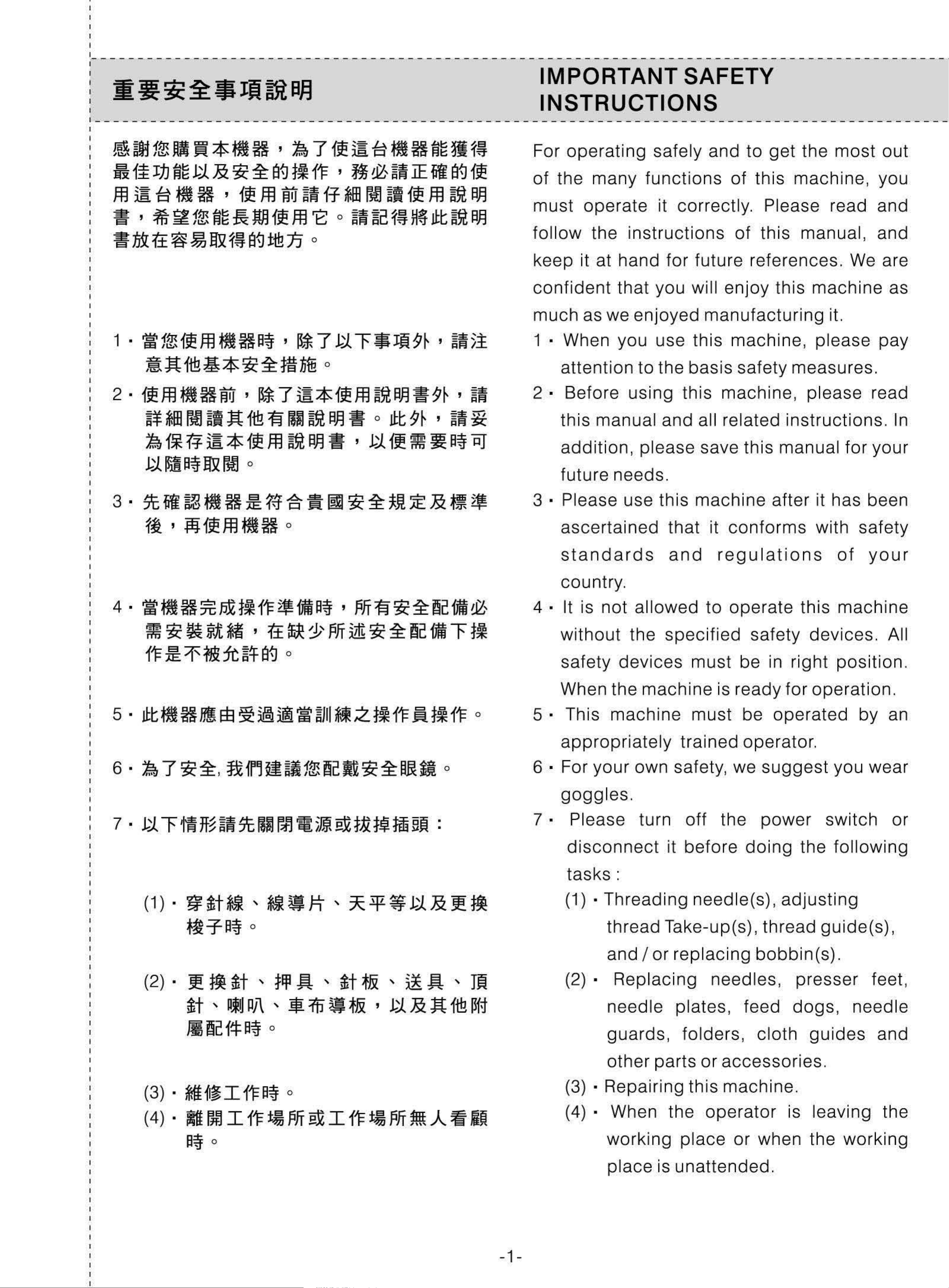
IMPORTANT SAFETY
INSTRUCTIONS
For
of
must
follow
keep
confident
much
operating
the
many
operate
the
it at
as
we
safely
functions
it correctly. Please read
instructions
hand
tha
t
enjoyed
for
you
future
will
and
enjoy
manufacturing
to
of
of
get
this
this
references
this
the
machine
manual
machine
most
,
. We are
it.
out
,
you
and
and
as
1 ·
2 ·
3-~~~f~H~~~~~~~~~~~~
~1flHfffl
~lt1iB¥*~~f~nffi
ff
ffl
~¥
~~~~*~ffl~~-,~~~~a~~
1-1~a~~m1
t~
*HI
m1
as
t~Ha~
Wi
~~
;tt
,
a#-
fiB
o
l[
'
7
~
~
~
7
o
*
~
ii
"""F
ff
a.F.I
=it
ffl
~
o
JW9~
a.F.I
JJ:t
=it
9
'
9
~
~ , ~~
:~51
,
~~
~
· When
1
attention
2 •
3 • Please
Before
this
addition,
future
manual
needs.
you
to
using
please
use
use
the
this
and
this
this
basis
all
save
machine
machine,
safety
machine
related
this
please
measures.
,
please
instructions.
manual
after
it
for
has
pay
read
In
your
been
~l ' :jij~ffl
4·~t~H~~a~~-a~,~fi~~~~-~
~~--~,~&~~~~~D~•"""Fa
f'F
~
1'~:ft~~
~H
8{]
o
0
ascertained
standards
country.
· It is
4
without
safety
When
not
the
allowed
the
devices
machine
that
and
specified
must
it
to
conforms
regulations
operate
is
ready
safety
be
in
this
devices.
right
for
operation.
with
of
machine
position.
safety
your
All
5 · This
appropriately
6 •
7 · Please turn
For
goggles.
disconnect
tasks
machine
your
:
own
it
must
trained
safety,
off
befo
the
re
be
operator.
we
doing
operated
suggest
power
switch
the
by
you
following
wear
an
or
( 1 ) .
( 2) . £
~
~-Ta~
tt
ll~cf!f:a~
~t
*fR ' *fR
o
fl
'
tt
PiU
Pj\
'
flfl
' It!
o
~
h '
~
:ftJ
'
tt
~
~
~&
3¥
~& ' ~
~
'
ii
ii
&
& £
~ '
;lt
fiB
fl
J~
~f;j
(1)
(2) ·
·Threading
thread
and I or
Replaci
needle
guards,
other
Take-up(s ),
parts
needle(s
replacing
ng
plates,
folders
needles,
feed
,
or
accessories.
),
adjusting
thread
bobbin(s).
presser
dogs
cloth
guide(s),
,
guides
feet,
needle
and
(3) ·
( 4) ·
*l~~I
M1t
a~
m1
o
1'Fa~
I
f'F
t~
o
f:ifi
§X
I
f'F
t~
f:ifi
1m
.A
;fi
.0
-1-
(3) ·
( 4) · When
Repairing
working
place
this
the
pl
ace
is
unattended.
machine.
operator
or
is
when
leaving
the
working
the
Page 7
(5) •
~ffffl
~ ~
H
,~
~
fffl
1m~&~
J:t
~]![
(5) • While
clutch
motors
without
brake
a~
,
!0~f~,~~ie~f~Jl:
o
8 ·
By
any
wash
clean
If
any
fluid
the
pads
to
completely
chance
contact
the
water
fluid
contacted
are
, if
and
was
used,
stop.
you
your
consult
swallowed
allow
skin or
area
motors
grease
completely
a
med
must
eyes, please
ical
contact
come
, oil,
doctor.
or
with
a
9·~~~~-M~f~~~-~~~2~&g~
~~H~5~~:SBOO~
1 o .
*it~~
,
11~
~
&
~~
m w I
o
11=
,
~
El3
~
i&d~
9
•
10
medical doctor
Do
motion
Always
switch
task
•
Qualified
not
is
.
touch
while
pay
on
attention
or
technicians
immediately
any
the
off
parts
machine
to
before
are
.
and
whether
conducting
devices
is
required
running,
power
in
any
for
11
~
{fffl
· -1m
~IY-JA~~~o
~JII
~
El3SIRUBAj~
*it
IY-J
{1~
j~
&
SiP
~~I
~
~~
-¥
~~Wf!:l=
f'F
~ ~ '
o
!IZ
,
~~
83
*it
~
{I~
i&!
a~
~
R
~
~!f
~JII
11
machine
repair. Only
are
Damage
are
·
Routine
to
recommended
subject
maintenance
be
performed
adjustment,
genuine
resulted
to
your
in
own
modification
parts
for
using
risk.
and
by
from
replacement
generic
check-up
appropriately
,
and
SIRUBA
.
parts
have
'
1 2 •
~
~=ft~Sifi~~
~&f~W,~a~•~••a~,~~lU
f~Jl:f!Hiifi
=f
W
f!:l=
*it
{I~
&
'
o
f*
~
il
El3
I
3~
f'F
m~~~
!JZ'
~~
ES
IY-J
~
.A.~~
)~
8{]
12
trained
technicians.
·
Qualified
persons
electronic
electronic
adjustment
persons
t
echnician
are
components
is
requ
essential
or
repair
ired
,
or
or
for
knowledge
for
tasks.
qualified
well-trained
services
conducting
Stop
to
of
the
13 ·
1±
S&~-I~M,~H~M~~~&&
f~5l~
~~~!0~~~~~'~H~H~&~
~IS
!IZ,
~
~ih~
~
~
Wf!:l=(f91J
ij.5~
~~
'
tt
~
~ifriHIH8{]Kd£
9~
~ ~ &
tt
fa~~
13 ·
machine
failure
components
The
machine
supply
and
air
hose
servicing
immediately
of
and
has
any
.
has
to
to
the
be
the
of
be
cut
when
the
detached
compressor
off
machine
before
discover
electronic
repairing
equipped
from
or
the
the
air
~
~
R
0
fa~
83
~
i&!
~
~
~JII
*l
8{]
t~
SiP
~
~~-¥
~
14
with
cylinder
trained
adjustment
•
To
periodically
ensure
pneumat
.
ic
Qualified
persons
and
the
best
clean
parts
repairs.
performance,
up
such
technicians
are
on
required
the
machine
as an
or
air
well-
for
is
necessary.
-2-
Page 8
1 5 •
~
1f
tl
H
UtLiE
m
f¥
11=
'
tl
iS
f!
3¥
JJi
~
15
·
To
level the
machine
on
the
ground
is
J:
I
I
1 6 •
11=
~
x~~r±t~HJ:,g•~~~-r±~~
~;Z-~J:
'
tl
0
m ~
H ~ ~
~
tr-1
~
o
1±
5ml
5~
fi
?.!~
~
PI
'
:g.
M!EE
119
li
~ r
ti
}~SiP~
-"F
fl
16
essential
operation
operating
surrounding.
· A p
this
connect
rop
er
machine
in
power
the
order
and
a
power
to
lower
machine
plug
by
electrician.
plug
ensure
must
a
noise.
at
be
to
a
a
used
grounded
proper
Avoid
.
nOISY
with
Please
receptacle.
1 7 • m H R :ft
m
18
I
•
~~~EX
~,~af~&~~l19~~m~,*~~
1'
~~1':ft~f8{]
WI!
5t<
Miff
~f
~
1f m
M H
ffl
*b
Ei
n~ t~
o
~,
~~~EX
~
1~
:AE
~.~
m ~ 1: , x
~
WI!
~
~Ji
M H
~
.&
P~
1t£
~
~I
17
18
· This
designed
machine
·
Any
this
the
machine
modification
machine
safety
can
purpose
are
not
must
standards
only
.
Other
allowed.
or
conversion
be
be
conformed
and
used
uses
regulations.
for
of
made
this
with
the
on
19.
ief~ti.:ZW
V'S-m5F
( 1 ) · ~
7 ~
t1~~~1~'~5F
1111=
~
o
~
M
:eX~~
~
f!
.:Z
~
=
.A~
Bft
.:Z
'
:~
11
m
~
:t=J
~
1m
Btl
f.ffi
~
~
19
Precaut
responsibility
modification
machine.
· Two
(1) • For
safety
service
ion
the
is
warning
necessary
for
or
safety
persons,
. We
damage
conversion
signs
of
please
are
operators
assume
caused
appl
of
ie
don•t
no
by
this
s:
and
open
1[H*i.:Z9~ii
~00.:2~14:
(2) •
I
~'~~~~1Jj
a · ~
fi
!t
~~
:£~$Jfj
1'
ii
0
r:ij
EX~~~
'
1±
~~
1!?.1'~Mfl1[H*ft
(2)
a
1m
JSl
14:
1;Wi
fl
II
'
'
=¥-
~
fT
}~
tl
the
boxes
don1t
to
·
Always
·
Please
with
cover
of
touch
avoid
belt
of
motor
electrical
keep
never
cover
any
or
any
in
mind
ope
,
electronic
othe
co
finger
mponents
shock
rate
r
:
this
guard
control
devices
inside
hazards
machine
or
and
.
any
b ·
Hflf'F o
~
31
~~ ' ~
~ ,
~1fffl~~
7
fW
~~~~Hflfi'
J:f:l
U:t
,
~
9
~
~
1~
li
8{]
=¥-
~
0
HB
=¥-
~
,
'
1li
fflJ
'lit~H
ert
gz
~
~
1111'
.&
.&
r:ij
~
f.ffi
ti5r
b
safety
physical
·
Please
cloths
"bobbin
while
pre
vent
device
injury
keep
away
winder
the
machine
the
.
your
from
risk
removed
hair,
the
", V
of
injuries
belt
is in
to
fingers
hand
and
operation
by
avoid
and
wheel
motor
tangled
to
into
c
•
c ·
I
~
1±
1±
J:f:l
1~
3.1
~t
o
:t=J
~
119
1m
J:f:l
-"F
~
1i
5ml
'
~
EX
00
1'
~t~~~~9~
fDl
r:ij
fl
~~ 1~
EX
~ H B
8{]
=¥-
:fj5[
it
Please
the
cover
switch
them
never
needle
when
or
.
operate
put
or
in
you
your
the
turn
the
fingers
thread
on
the
machine.
under
take
power
up
-3-
Page 9
d ·
~
~
H
5.1
ft
I=P
'
f~
firt
~ ~
ft
d
·While
the machine
is
in operation,
ih ' ~ 7
1~
~
-T
~
t~
a~ ' ~
, &, ~
firt
~f1lli:
~
ftz.
~
'
~ ~
5mi
fg-¥ ~
~
JJ:t
1m
9
~ ' ~
mJ
~11
a{]
tt~
¥
B
~11
~I
1*
!1!
~
f~
t~
~
o
z
~
t~
the
Please keep your hands away from
the area of
injury
please make sure
power of the machine
changing bobbins.
hook
to
rotates at a high speed.
hook
your hands.
to prevent possible
to
In
turn off the
addition,
while
e · ~
¥
n!r.m
.mn~t~H~=P
EXtil~~fi~ta~
o
'
,J,,GW
~~
·
e
f · Please turn off the power
Be
inside the machine when moving
raising the machine head to avoid
possible physical injuries.
machine before
head
careful not to place your fingers
tilting the machine
or
removing the belt cover and
of
I
the
g ·
~c
it
~~tW~~Piffa{],
f!
~
,
~
H
~
1m
a{]
~
H M iji!
?.~
.®
H ~
11:
ih
iffi
De
AA
~I
.m
~
a~ ' ~~
~
~
~
7 itiftz.
~
~~
~~
it
U~
~
the
accidents due
machine.
g • The
while the machine is at rest
machine is
motor. So,
V
motor
belt
to
to
does not produce noise
equipped
please turn off the power
avoid
abrupt
with a servo
possible
start of this
if
your
9~ ' i!i!r~~~l1f~f~H
h ·
~
1±
7~ftz.~~Z~Bft
'~
fto
i • ~ 7
~5mi
'~~~~~
mJ
~f£~~EX~r~1!f::t~fliffi
~
5mi
:ti
tfu
ti
o
~l
f¥
1'1=
~
of this machine to avoid
accidents due
machine.
· Never operate the sewing machine
h
with the ground wire removed to
avoid
i · Please turn the
possible
to
electrical shock hazards.
abrupt start of the
power
switch
off
in
~ 1 ~
5mi
~-------------------------------------------------------------------------------------------;
'
z
:jij:
~
tEa
tt~
J:
~
EX
t~ t~
9~ , ~~
tm
5t
firt
o
tn
Iff
~
prior
disconnection of the power plug to
prevent
electric
electronic components.
to
possible accidents due to
the
shock
WARNING
--
----------
-
------------
----
----------
-
--
-
----------
----
-----
-
--
-
---
-
----------
connection
or
damaged
-
--
------
or
-
--
I
I
I
I
1
Please confirm the following to avoid
malfunction and
• Clean this machine completely before
1
putting this machine in operati
first time after set
damage
up
to this machine.
on
.
for the
-4-
Page 10
2 ·
Clean
transportation.
all
dust
and
oil
gathered
during
5·W~m~~-~~~~~~at,~~~~
fflf~Ho
3 ·
4 ·
5 ·
Confirm
and
Confirm
connected
Never
type
shown
phase
is
that
that
use
different
on
the
(single
the
to
the
the
the
machine
motor
voltage
or
power
power
to
the
3
phase)
plug
where
designated
nameplate.
are
supply.
set
of
is
properly
the
correctly
motor
voltage
on
.
6 ·
Warning:
Before
adjustment,
prevent
Confirm
of
the
doing
machine
accidents
that
the
please
the
following
direction
pulley
turn
caused
the
of
is
correct.
operation
power
by
abrupt
the
rotation
or
off
to
start
of
the
~
--------------------------------------------------------------------------------------------
!
I
t----------------------
5Eb§~~
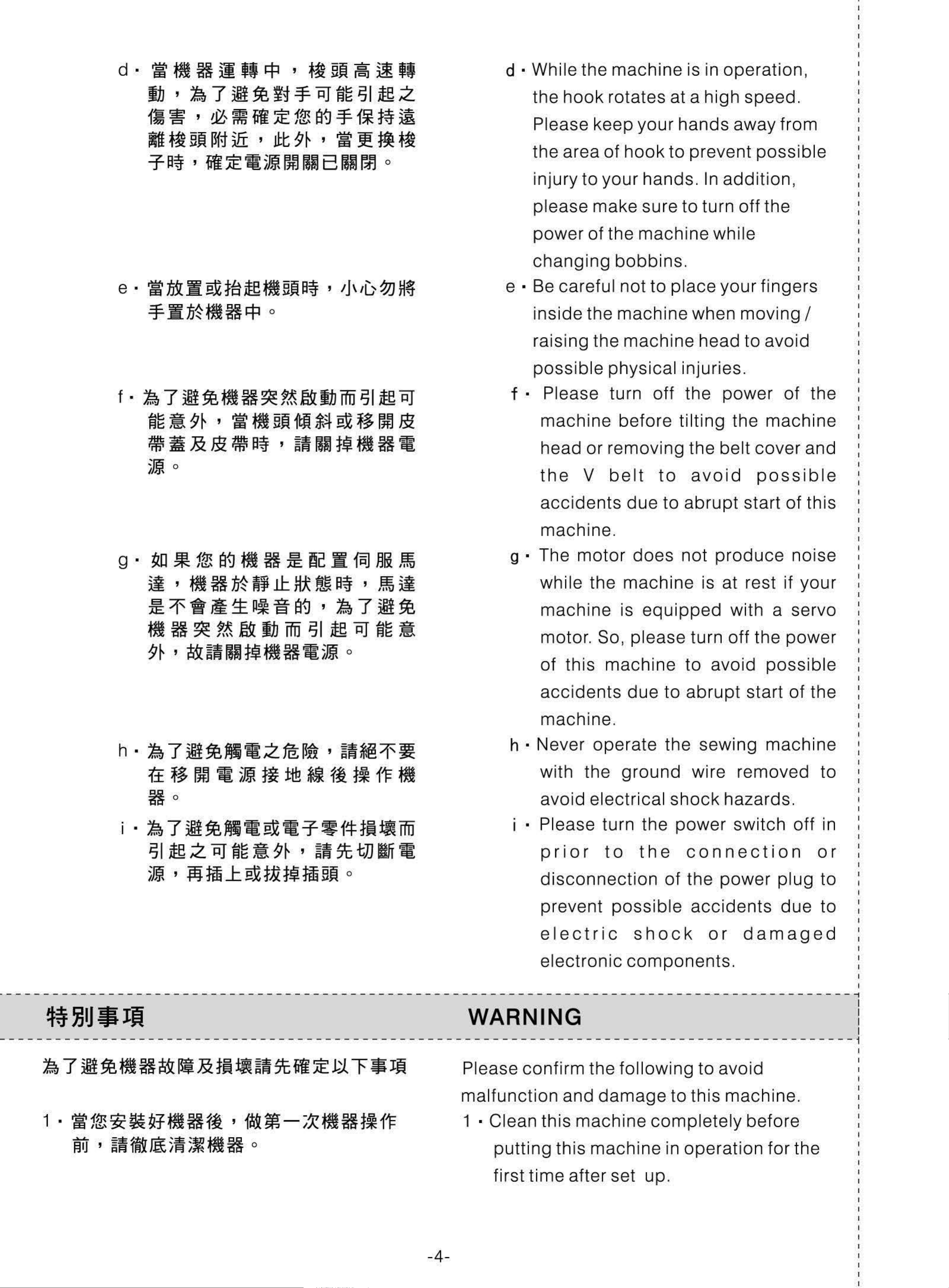
1 ·
5m
fi
1)
!IZ,
~
'*
ii
n~
~
-
---
~.&
l!:!1
-
----------
ffi
'*'
.:z
1m
-
~
o (
OIL
-----------
1 ·
sewing
PAN INSTALLATION
-
--
The
the
the
-
-----------
corners
four
machine
machine.
-
of
corners
the
at
table.
--------------
oil
the
(Fig .1)
pan
cut
has
out
-
------------
to
groove
place
on
of
2·m~~~ffi~zn~®,R~®•m~oo~
~M
.:Z~~R~@~OO~@~~MB~(~
•
a{]
A
il(f~1'F~1.J~)
:n
~)
,
?&
fl
:jij
w~
'
:jijffl
5m
m@
~~~t~~
'*
J:.
o
(~2)
2 •
Use
seats®
Use
cushion@
Place
) .
nails®
on
rubber
oil
as
side
based
seats
pan@
illustrated
A (the
[11/Fig.
operator
adhesive
on
on
the living
the
fixed
to
1
fix
to
side
two
ls
fix
two
rubber
side)
(side
.
8
-5-
seats
. (Fig. 2)
Page 11

1
25mm
25mm
4
3
........
1-------A
3·~~~~~~~@~~~--@~M,
~~-~oo•~~~~@~~JL~,~
~~d~&M•~m~•~•~-~~
=@000~
0
([13.4)
3
Br------•~
· Pl
ace
holes
the
install
bed
the
before
four
the
that
hinge
place
00
the
cushions@
machine
has
two
openings
~2/Fig.
into
the
2
two
fixing
machine
of
head
the
onto
desk.
the
with
rubber
head
onto
Then,
machine
cushion~
of
each
. (Fig. 3, 4)
II3/Fig
~~
- --------
--------------------------------------------------------------------------------------------
1 ·
~l15~~aFJ(!I5)
(1) •
- - -
------
1~m
~A
- -
~m
o
5m>1.A5m~~
--
---
-~
------- -
,
RlOO$tJ~
--
.3
- ------
------
OIL
1 • Oil
- -
(1)
-~
----
---------------
LUBRICATION
lubrication
· Fill the oil pan with
high
mark
instruction
specified
A.
~4/Fig
--
--
-
-- ~
(Fig .5)
---- -
oil
up
.4
to
----
~
~
( 2) • ~
(
3)
•
~D
Rl
~~;~MJ5~5m
~
~
.1-1
00
;IM]
fft
5~
ftt
5m
n~
lE
~
1ft~
o
~ ' ~
e2>
~
B
a~
~
~
$tJ
,
~
%S
fl1'F
PA5m
)~
IJ[
1JD
~ ' f~
~
tiff~~
o
(2) · Refill the oil
if
the
oil level is lower
B.
(3) ·
You
window
will see oil
(2)
well when
if
mach
pan
splash
the
with the
spec
below
ing
via
lubrication
ine runs.
ified oil
low
oil si
mark
ght
functions
-6-
Page 12

(4) •
~~.ff~a~-;~~''
,
§X*~i&!-~~a~
(4) •
When
running
the
machine
first
time
( 1 ) •
ra~*1fffl
1~t~1±3,000~Ij3
)EB
QJ
I
it~
1fffl
fff~~.t~
'
[jt
WJ1
m
O;t~[jt]f[;Z'i~
0
,
500
*'92 5 m m X 7 0 m m '
;Z[jtl£
S.PM
0
'
:~
.
.:Zra~
(~6)
o
2
·Adjust
amount)
(1)
or
your
S.
• Oil
x
accepted
after
machine
PM.
the
.
splashing
70mm,
a
for
oi l
period
about
amou
test
any
.
Paper
material
at
nt
of
3,000
10
time, please
S.PM.
mi
of
the
paper.
material
nutes
hook
of
to
.
(oiling
About
test
will
pape
not
run
3,500
25mm
r is
(2) .
~~5m:i:11L~
~ ' ~~
(
CD*~
@tiM,.li@Ji:~
7)
fi~
5Eb
(2)
:i:
m ®
~ ~
o
[jt
5m
m
~~[jt*ft~~5mm
*!
@il~
~
n~
'~
fi~
"'"F
1J
o
(2)
affect
•
Confirm
pape
pape
oil
(j)
@
pan
HOOK
TOUCHING
results. (Fig.6)
the
r
under
r cl
ose
. (Fig. 7)
(2)
oil
ly
PAPER @OIL
amount.
the
against
@BASE @
hook
Place
and
to
the
PAN
BUSHING
fit
wall
the
the
tes
of
t
the
LD
N
70
6/Fig.
6
A
E
E
0
B
~~rr~(2)WUa~
Wff.:ft~MJ.;Z~fi~
3.
>t~~rw
(1) ·
~~an!6*1t1~AA~
~
:
3
;t~Pi]i[
'
l~OO
o
o
5~~.&M!~I=m
,
~~5t~~~a
~5/Fig.5
1j\1G
'
When
sliding
fingers
3
·
Attentions
(1)
doing
plate
.
· If
the
enough
step
and
:
machine
(2),
do
,
please
carefully
not
touch
doesn
run
remove
the
't
warm
the
machine
~7/Fig.7
the
hook
up
with
3
(2) •
1±~H~,~~ ' ~~5Eb:m:ii~[jt*ftji
;fj~
*~
fi~
"'"F
1J
0 (
~
7)
-7-
(2)
minutes
· While
the
hook.
oi l
idly
the
splashing
(Fig. 7)
machine
.
is runni
test
paper
ng, place
under
the
Page 13

(3) •
m
~5
m~
5
m
m(5
m00
)
1r
JJ~
"'
~
.n
w
(3) ·
Conf
irm
that
the
heig
ht
of
the
oil level
(4) • ~
1'1=
IF
ftt
,~
(
ffl-=¥-
.fl
1±
~
I]
5
f
~
Ji
ra~
j}
~P'J~.oXm
~Jt
lj
a~
0
ra
~
)
0
~5
m
•
zjjj
5
in
L
( 4) · Oil
be
watc
· A
sample
appropria
Oil
amount
the
OW
splashing
complet
oil
".
h
to
of
observations
te oil
in
pa
check
n
falls
ob
ed in 5
amou
the
hoo
between
servation
seconds
the
nt. (Fig .8)
time
indi
k
(small)
" HI "
test
used
cate
as
and
shou
. (Us e a
.)
the
shown
"
ld
is
(1) • 5m
f¥
~
(
-M
~nol-i
:eX
t~
I&J
fi
~
H~~~~)
~iff
6
~
,
f9
tl
~,~
mJ
~
o 5m •
,
; 5m •
m
tn
I&J
m 1
Y ,
tJ&
i&J
]![
!e
Ml
*~
~ ' ]
2 •
*~fift5m:m:~~~~fl
,
H~~a~•t3o'!:P
,
2
·After
the
amount
of
oil in
the
hook
is
I
I
1
I
l
----
1-:1.
~1ff~~•~*~fift5m
ita9~~
-----
----
-
--
-
-----
-
---
:m:
--
o
---
-----
--
--
-
--
-
-----
properly
for
observation
of oil in
30
seconds
adjusted,
test
the
hook
INSTALLING
-
--
-
-----
-
--
-
-----
run
to
do
to
.
reconfirm
THE
-
-----------
the
oil
splashing
machine
the
NEEDLE
-
idly
amount
-----
--
--
---
0
3~~-~&mfl~m~•~-~~
i~
2·~•~**C2>~~tt~CD,~~~m~~g
51*
'~lm~~~~~t
0
(!110)
~~
Choose
type
used
needle
1 · Turn
2 •
a
right
of
bar
Loosen
the
.Turn
. (Fig .1 0)
the
to
the
its
needle
thread
power
hand
highest
screw
wheel
and
off
position
(2),
and
size
the
to
type
before
raise
hold
according
of
placing
.
the
the
the
needle
needle
to
material
the
the
CD
ffiA~WOO~~~Bo~~~~~A~C
WWOO~~D
o
with its
right
long
exact
3 · Place
needle
hole
in
groove
ly
in
indented
direction
C
to
the
bar
the
the
needle
all
arrow
side
B ,
of
left in
the
the
into
way
direction.
A
facing
and
needle
direction
the
to
make
is
hole on
the
end
exactly
sure t
facing
D.
the
of
the
to
hat
- olf
I
I
~--A
C
--+~
B
..
4 · Firmly
loc
(J
k
screw
(2).
A
(
l------------------------
1·~~~~M~•~,~m~~~~~~~
~~~
0
(1111)
-----
111
0/Fig
.1 0
SETTING
---------------------
1 · Set
------
the
way
that
B
c
THE
BOBBIN
---------------------
bobbin
the
thread
in
the
wound
bobbin
direction
case
ii11/Fig.11
---------------
in
the
is
2·~~~·~~•A•,~~c~~~
~,~tt,~·~·~~~~:CD,~
83B.$kD.lli
o
clockwise.
• Pass
2
and
thread
spring
notch
the
pull
will
CD
B.
(Fig .11)
thread
the
and
thread
be
pulled
will
through
in
be
direction
under
pulled
thread
the
out
slit A ,
C.
tension
from
The
-9-
Page 15

3-~~c~aa,,~~-~~~-fi~~f~~
3 ·
Be
sure the
bobbin
rotates
in
the
direction
~fj!IJ
~-------------------------------------------------------------------------------------------~
----- -
----------------
0
-
---------
-
----------------
as
toward
the
ar r
C.
ow
shows
THREADING THE
-
---------
-
----------------
when thread is pulled
MACHINE
-
---------------i
I
I
~12/Fig.12
STITCH LENGTH ADJUSTMENT
--------------------------------~--------------------------~-------------------~------------J
1·~ft~f~~~~fi!IJMR§~~&®'~
M~Pfi~ll*!~~~~
A o ( 13)
1 ·
Turn
indicates to have the desired number
with mark A on the machine.
stitch length dial
®as
the arrow
(F
ig.13)
align
2 .
3-~~~~MR§a,,QJtJMm~~e®,
~
~
IE1
a'
e
M~
J:.
1&
~'J
*~
m
®
Iti
~i
11LA11
1'"
~
r~
o
o
2
·The
3 · Press the feed
stitch
stitch
calibrat ion on the dial is in millimeters.
length adjustment dial
length.
lever®
down and turn the
®to
change
~13
/
Fig.13
-10-
II14/Fig.14
Page 16

I
- - - - --·- -- -- - - - - - --- - -·
I
---
- --- --- - -
---
-·- -- - -- - -- - --- - -·- ---- -- - --
---
-·- -- - -- - -- - ----
---
- -------- -
---
-------
I
I
l
--------------------------------------------------------------------------------------------
-~~~
THREAD STAND ASSEMBLY
1 · Assemble the thread stand set before
installing. Place the thread stand set
the hole on the table top. (Fig.14)
· Fix the thread stand with a nut
2
under the table
top
.
CD
l
onto
ocked
~--------------------------------------------------------------------------------------------
:
BZ~§&~t.:.f~-HZ:iC~
THE
BELT COVER AND
! BOBBIN
l
___________________________________________________________________________________________
I
1·~·~-~~~mJLA'B'C'D
(1;15)
2 •
~~Hlt;Wi~Si~~~
'
~A~~JLt:f:l
o
o
1 · Grinding holes A I 8 I C I D on the table
top.(Fig.15)
· Insert the belt cover sup port into the
2
WINDER
THE
MOUNTING
_
bolt
3·~$t,Wi~@MM'~~~-~~~~~
~~~·tu
5·ffl@'@~H&@-~'~Hlt;Wi~~~
0
3
4
5 · Use
hole on the machine.
· Tilt the belt
the hand
the hand wheel.
· Put belt cover ® on locating holes C and
D.
screws@, @and
cover@
wheel
then you can install
diagonally
washer@
from the rear of
to fix the
:o~t~wm~~~w~
6.
7·~-~~Hlt;Wi~®,~~~~-M&Hl
~~(/)~~Hlt;Wi~@
t,Wi~@~*~H&-~,~~JSit,Wi~®~
)Eo
o
0
belt cover on the machine
the screws tightly.
· Place
6
7
· Move the belt
its rubber cushion touch the belt
Fix the belt
cushio
the(/)
n.
to the belt
cover®
cover®
by
body
cover@
backward and have
wooden
and
.
cover@.
screw and
lock
8·~~~M~H@~~M~mJLA,B
~0
i
•
· Mount
8
8 on the table top.
bobbin
winder@
c
to
holes A and
~
"\
/ J
-
1\
B
ii15/Fig.15
-11-
Page 17

--- -- -
---
- -------- -
---
--------- - --- - -· ----- -- - ---
---
·- -- --- - -- - -- - --·
---
- --- --- - -
---
-·- -- - -- - - - - - - - --·
---
- --- -
I
I
- -
-
- -~- - -
1-~ma~f~Am*~'~•~f~Am*
2-~~~fflB~f~Am*~~~~U®,
----------------
~Jlt~:10mm
o
16
--
- --- -~- - -
.17)
----
---
--
-----
ADJUSTMENT
PRESSER
--
1
2 •
----
·The
using
I
ifter
By
adjusting
- - -
----
standard
knee-control
. (Fig .16, 17)
FOOT
--
- -
lifting
the
OF
KNEE-CONTROL
LIFTER
-- --
screw®
---
height
presser
------- --- --- -
is
10
mm
by
foot
at
the
knee
-- --
:
1
3 ·
M~f~Am~~13mm
o
controller,
up
~f~A6m~~Ji~i&J1
~fi~ffB®~~!tfiL&f~A@J:ffB
omma~
,
~~m~~t
o
3 ·
When
lifted
of
does
to
the
no
the
13mm
the
over
presser
.
1 Omm,
needle
t hit the
presser
foot
assure
bar®
in its
presser
foot
is
adjusted
can
the
lower
foot.
be
lifted
to
bottom
position@
be
end
~16/Fig
.
16
OPERATING
The
foot
pedal
is operated as the following 4
THE
PEDAL
steps. (Fig.18)
1
· Lightly tread the front part of the
i)17/Fig.17
foot
pedal
2·~-W~BM~M~a~,~DA,~~~~
~
til§
3!
'
~
~~M~1fjr;JJXiiiJM~l¥ij~i!ii
'I(~D
~fit
5t
~~:A£~
~
j1J
ii!J
M
rJJ
) o
shown as
Bin
Fig.
19
, machine runs at low
sewing speed.
2
• Further, tread the front part
shown as A in Fig. 19, Machine runs
sewing speed. (The machine runs
speed after it
comp
letes the
the automatic backstitch has been preset.)
of
the
backst
foo
t pedal
at
at
high
itch if
high
3·•~•m~~mm,
(~t
1±
J:
§X
"'f) o
4·~-~jr;~~-B,
j1J1'F
0
~oc,~~~~'~jtJ
~DE'~~~fi~~
• Reset the pedal
3
shown as
C
(with the needle up or down.)
4
• Fully
depress
shown as E in Fig.
threads.
to
in
Fig. 19. Machine will
the
its original position,
back
19
part of the
, so that machine trims
stop
pedal
-12-
Page 18

5 .
)
!~$Jfij
( 1 ) ·
~D
~
H
:
{~
,
~H~.Ll:Wtn~ih1'F.Zra~!f~
a{]~
H
~f~
~
tfJI
~
13
11.1
t~
3t
5 · Attent i
·
(1)
One
machine
ons
extra
:
step
stop
is given
and
thread
between
trimming
the
7
t&
~ , ~.ttf:rtn~lh1'F
-11W!I
'
~D
D '
tfJI
'
HP~f~t
~
~
J:.
o
~t~fl
t~
3t
~~UJ'al1~!
' ¥ij
~!
"""F
steps
the
lightly
pedal, sh
goes
if
pedal.
auto
you
if
your
depress
up. The thread trimmer actuates
furthe r tread
machine
presser
the
own
as D,
foot
back
the
the
is
equipped
lifter. When you
part
presser
back
of
pa
the
foot
rt
with
of
the
( 2) ·
(3) ·
~
[§]
~
HPf~~Htt~~:eXftt~~
~IJ
m
ifiJ
~i
JJX
~~
a{]
M
fl
lfalJ
tn
11.1
¥11
I*
:;t
~!
~
1'1=
13L
{~
t&
11.1
~Jt
~ ' ~ H
fT
.L1:
ff
fl
11=
a
0
~
o
~ ' ~D
!I
'
'B
~
tt
~
~~
iiiJ
*
lfalJ
M
'
R~:ll
~Jt
~!
11.1
fT
~.&
1'1=
lE
(2) ·
(3)
· Whether the
Machine
backstitch
its neutral position
the
speed
make
automat
the
wi
or
ll
stop
if you relocate the
ic backstitch.
machine
low
mach
speed
afte r
ing
complet
during
is
under
sew
doing
ing, you can
thread
ing
pedal
executing
high
the
to
(4) •
~D~1±t!HfJtfjtJJ~Ih1'Ffl
n:IIJ~~~at&•ml*m~c,t~Hm
~~~1JXtD~Ih1'F
o
'
HPOO
( 4)
trimming
back
· Even
neutral
the
action,
perform
if
machine
any
part
you
pos
the
thread
time
of
the
reset
ition C
started thr
machine
pedal
the
trimming.
by
immediately
tread
to
foot
ead
will
complete
down
do
pedal
so.
trimming
the
to
after
its
ly
(5) ·
~~t1~1±"""F;E1ll:a~
m '
f!IJM~~~!~.&fli*-~X~D1ll:~HP
,
~o~~~~t
J:.
"i5Jo
(5)
• When the m
the
end, tread the
pedal
need
needle
once
le up.
achine
located
back
to
D if
you
stops
at
the lower
part
want
and
of
the
to
makes
dead
foot
bring
the
I
I
I
I
I
I
I
I
I
I
I
0
0
A
B
c
D
E
(j
(j
0
00
~
D
(}A
8~
@
(}
c
®
!118/Fig. 18
-13-
~19/F
i
g
.
19
Page 19

______
_
__________
_
_______________
_
__________
_
_______________
_
_________
_
________________
_
____
J
I
- -
-
- -~- - -
----------------
(1) ·
11-'<Jrl~a~~n
~
ffiU
tH
CD
'
--
rtil(A
tJJ
~
- --- -~- - -
n
fl
rtil),il11~t~f~~
i11±
~t e~
----
---
z ~
--
~
NEEDLE
TENSION
-----
--
1 ·
----
Needle
(Fig.1 9)
(1)
- - -
• The left
be
THREAD/BOBBIN
ADJUSTMENT
----
thread
shorter
--
- -
thread
-- --
tension
after
---
tail on
thread
------- --- --- -
adjustment
the
trimmed
needle
THREAD
-- --
will
as
1
(2) •
(3) •
fl~:e
11-'<~a~•n
~ffirJjHCD
11-'<
~ffiUM®
~~~~a~~
0
rtil(
,
n
rtil
'
s n
~~w~
rtil),il11~t~t~
( c n rtil)''
tt~~~~Ji~~
o
111
~t
~
o
~~
~
~
(2)
(3)
you
cl
ockwise.
·The
thread
counter
•
Increase
thread
turn
left
thread
(in A
thread
tension
clockwise
the
by
turning
tail will
nut
tension
tension
direction)
be
CD
(in 8
thread
is
on
nut
turned
direc
needle
tension
CD
longer
tion).
, as
nut
2 •
(
4)
'~~(~~)~~~fi~~~
( 1 ) •
·
11-'<
~ffiUtff®
11-'<
!1!1**®'
~a~~
~~~~
a~
~
n
rtil
'
n
rtil
tt~~~~Jiflf~
~~~~fifl~
( o n
( E n
rtil)
rtil)
''
''
111
111
tt
~
0
~
o
~
~~
~
~
mu
2
®clockwise
•
(4)
•
Bobbin
(1) • The
Reduce
by
counter
increased
the
turning
clockwise
thread
bobbin
(in C di
tension
thread
tension
thread
as
tension
rection)
on
tension
(in D
adjustment
tension
needle
nut®
direction
will
adjust
.
thread
).
be
screw@
is
turned
( 2) •
~-------------------------------------------------------------------------------------------l
-lm~~
1
%.il*il'.tl.
------
-
-----------------~--------
11-'<
~
a~
!1!1*'*®
:tR
ilrl~~~~~sq
'~
Jq
•
:n
'
~~~~~fi~J~
RIPJ
rtil
M
( F
:n
rtil)
111
~~
0
~
~
ffiU
THE
ADJUSTMENT
-
----------------~---
(2)
·The
reduced
counter-
THREAD TAKE UP SPRING
-
-----
clockwise
bobbin
as
clockwise
-
----------------~---
thread
screw@
(in E
tension
is
turned
(in F
direction)
direction).
.
will
-
be
I
I
I
----------
J
3
1 •
Adjusting
the
1120/Fig.
stroke
of
20
thread
take
up
(1) •
(2) •
J'j~f~!l!m**®
11-'<Jrl~a~~n
jH(3)
'
~~*El5MiifT~~W~t~1JD
o
rtil(A
n
rtil),ll11f~~~~
o
spring
•
(1)
(2) •
Loosen
The
spring
tension
(in A
CD.
(Fig.20)
stroke
direction)
screw®.
of
will
knob@
be
the
increased
thread
is
turned
.
take-up
as
the
clockwise
-14-
Page 20

(3) •
~~a~~n
~til(
s n
ltil)twlhf~~~ti
(3) •
The
stroke
will
be
decreased
as
the
( 1 ) ·
(2) •
tH@
M:
fff
M:f~!t!~**@
~~
"""F
'
~*i*~~M:ff,~M~~~~,
!t!~
0
**
® '
1EJ
0
a~ M~
~
ti
o
~M:
*-H@
2
the
clockwise
·
Adjusting
spring
(1) •
(2)
Loosen
tension
•
Loosen
knob
CD
.
the
screw®
disks@
screw@
@is
(in 8
pressure
turned
direct
.
.
.
counter-
of
and
thread
ion).
take
remove
up
thread
(3) ·
(4) •
~~~~~a~~n
ttl@
~~a~~n
ttl@
'
~ti*~~Miit3L:tJ
,
~ti*~~M:13L:tJM~~~~,
ltil(A
ltil(B
n
n
ltil)t511JJ~~~ti
M~~1JD
ltil)twlhJ~~~ti
o
o
(3)
(4)
·The
·The
pressure
tension
(in A
tension
clockwise
direction).
pressure
knob@
knob@
will
will
(in 8
be
is
be
is
direction)
increased
turned
reduced
turned
as
clockwise
as
counter
.
L-- -
1
I
!
I
·--·
----------
1-~~H~~,~~-Anltil
--
~~~~
-
---
--
:¥ttl!
CD
o (1121)
---
7t
- -·
--
'~
-------------------------
------
-
------
-
------
lht~Am*~
------
- -·
--------------·-----------
----
-
--
--- - -
--
---
MANUAL
LIFTING
1 •
Stop
foot
keep
lifting
the
it
up
----
----
--
PRESSER
LEVER
-·
---------------
machine
lever
.(Fi
g.21)
and
CD
up
----
FOOT
turn
(in A
-
----
the
direction)
-- -
presser
----
-
----
--
·----------
to
2 ·
2
}lfJ
~~-B7Jitiltt"""Ft511JtlfJAm*~CD~'flfJ
AM~~l@l~l*1um
AM~
J:.
f~
*
*-'9
5. 5 m m '
o
.Mil~
~
;Z o ~
·The
5.5
Turn
direct
orig
presser
mm
hand
ina I position
and
ion)
foot
will
lifter
to
release
will
remain
lever
.
be
CD
presser
lifted
at
down
that
up
(in 8
foot
to
position
to
about
.
its
CD
B A
(_..)
!122/Fig. 22
ji23/Fig.23
-15-
Page 21

--- -- -
---
- -------- -
---
--------- - --- - -· ----- -- - ---
---
·- -- --- - -- - -- - --·
ADJUSTING
PRESSURE
---
- --- --- - -
PRESSER
---
-·- -- - -- - - - - - - - --·
FOOT
---
- --- -
I
I
I
I
I
I
I
- -
-
- -~- - -
1 ·
2 ·
----------------
n5t
J:~
1~
~CD
~
!1!1
ftl!
i2!
a~
a~
-BJ
t.J
~
(2)
~
1J
, I!!
,
!l
~CD
fiJJ
t.J
;JiiX
~
( s
--
~~~~
a~
a~
1J
- --- -~- - -
~
,
1J
I!
fiJJ)
y o
fiJJ
t.J
itJ
----
(A
t~
J:~
1J
fiJJ)
1JD o (!;22)
Jt
sri
---
t.J
--
tw
~
itJ
!l
-----
--
1 ·
----
- - -
Loosen
regulator
increase
(Fi
g.22)
2 • Turn
clockwise
----
nut
the
--
(2),
CD
cl
presser
presser
(in 8
- -
-- --
Turn
---
presser
ockwise
foot
spring
regulator
direction)
------- --- --- -
spring
(in A
pressure
direction)
.
to
CD
reduce
counter
-- --
to
the
J
presser
3 . ~fl~m ,
~~~!I!!«-BJ:C2)
o
3 •
4 •
Lock
For
regular
nut
4·--~flJ:~Ji~t.J~fl~~~fl~t.J~
5kg'
a~!lJ:~f!~&t.J,~~~m~u~~~•
~~*31-~?kg
0
(1~~*31-~~)1
'
~
-~~)
the
pr
heavy
sewing
presser
foot
(2)
pressure.
after
adjustment
fabric, the
esser
fabric
foot
is
?kg. (To
should
result, please
foot
pressure
is
done.
normal
be
set at
have
adjust
pressu
the
the
according
re
5kg,
for
best
proper
to
the
of
material.)
--------------------------------------------------------------------------------------------;
----
~-
----------------
i(j
¥ij~~~!l!l**
~~
:eX
&
i(j
fi~
1J
0
([123)
-~--
fiJJ
''
-----
itJ
~
~-
J[J-
--
8
--
--------
~
( 1 )
--
f~
'
--
FEED
-~
-------
1 ·
Loosen
eccentric
cam
TIMING
~-
CD
-----
screws
cam
in
the
direction
--
ADJUSTMENT
-----
(2)
CD,
and@
move
--
of
--
-~
on
the
the
-------~------1
the
feed
arrow
feed
eccentric
or
the
I
I
2·---~~fl,~S~Ji~-~~fiOO
a~,~~Jt•~~-&~~~JL~•~
flW~tfi~tf.IJX-*i
o
2
· The
opposite
the
screws
standard
surface
needle
needle
below
of
eyelet
plate
the
direction
firmly
. (Fig.23)
adjustment
feed
dog
with
when
needle
pl
of
the
and
the
top
feed
ate
arrow, and
the
dog
.
is
to
top
leve l
end
surface
descends
the
of
lock
top
of
3 •
~D
1J
4 •
' '
'.:r
II,~,·
~D
i(j
.::Cc.
E3
•
~ ~
fiJJ
ax
fi~
tw
.
~
1J
*31-
itJ
1JD
fiJJ
~
te
*31-
~
Jt
• M
Q
I1J
i=l!!
1'
~
.fE
a~
Jl
~
'
M~
r~
Jt
t~
'
a~
M o
~IJ
ra~
f~
M~
,CJ-
f~
~
8
,CJ-
f~
tAli
8
0
1~
~
icr
11.'<
~~
&
3
· If
the
fabric
the feed
eccentric
4
·To
feed
cam
increase
timing
in
Attention:
timing
cam
the
opposite
fed
is
by
in
stitch
by
moving
not
enough
moving
the
arrow
tightness,
the
di
rection
,
advance
the
feed
direction.
extend
feed
eccentric
of
the
the
arrow.
1'
~t
I5J
0
M~
f~
,CJ-
c:J
~
*~In
~
* ,
1-1
~
I5J
a~
51
ite
IBfT
Please
too
far
do
to
not
avoid
move
the
needle
feed
eccentric
breakage.
cam
-16-
Page 22

r"
0
CD~
I
; o
a
r-
01
}
0)
0
~
I
~
-t
~
0
'-
Iff
t
~
.Jo
§) §)
-
0
b
c
t"'~
1123/Fig.
~--------------------------------------------------------------------------------------------
23
1124/Fig. 24
'
ADJUSTING THE ANGLE OF TILT
'
!
·
--
'
i~
--
1 ·
lt
--
'i'
1tft
-
--
1±
Az
~~
-
--
~
ftl*~fi
11
--
*
~~
--
- -
lmJ:.
HP
----
a
{]~251JiA
.5X7J<.:lfl~~
--
--
- -
W
---
B.BX
o 24)
- -
---
- ~
- -
a
---
~ , ~
-
-----
OF THE FEED DOG
--
1 • When
--
-
ali
--
gned
-
----
ma
-
----
rk A
with
on
ma
-
----
the
rk B ,
feed
- -
the
---
--
bar shaft
angle
-
--
of
-
------
is
tile
-
--
-
--
2·~
**CD
90/i
3
·
~
7
7
•
'
-
~•
'
~
~
~
"ill
~lftt~A
~*
M
~
e
1
~,~~u
~
'G
lm
imft
"~"~
e~
(2)
l*~fia
~,
1
~
~
~~~
H
ft
o
1J
~-~
~
Q
~G
lh
~
becomes
• To
2
the
feed
the
front tilt
3 · To
horizo
prevent
screw
dog
direct
prevent
CD
eccentric
ion
ang
ntal. (F
fabric
by
of
le
uneven
of
from
a
screw dri
the
the
ig
puckering
shaft
arrow
feed
fabr
ic
. 24)
ver and
(2)
to
dog.
feeding
90
reduce
degrees
,
loosen
tu
rn
the
, pl
ease
the
in
4
(2)1~~HJL
ftl*
·
~
~
~
lic
~-
,m
~~
&JJ
o
(~
~·
*
~m~m~m
A
M~m~mm~~~
llh90Ji
'
"ill~ftt~
*~~!la~)
,
J
~~•
m~•
~
~
f~
~
Ka
turn
degree
This
angle
for the
·After
4
dog,
the
could
adjusting
this will
feed
opposite
decrease
of
th
the
ick
feed
mate
dog
the
change
eccentr
to
dog
rials).
the
tilt
ic
ar
row
the
"c" (while
angle
the
backward
he i
shaft
of
ght
(2)
direction
ad
the
of
90
tilt
ju
sting
feed
the
.
feed
Ji
I
- --
I
I
!
I
[ ______ _____
----
- -
i~A~Jl
o
--
-
--
__
-
--
___
-
--
___
----
__
__
--
__
--
------
__
____
----
--
_______
-
--
-
______
--
-
--
___
- -
dog
after
dog
----
- - - -
.
Therefore, please recheck
agjusting
.
---
- -
---
the
----
tilt
-
--
angle
-
--
- -
of
--
its
the
--
- - -
height
feed
----
- -
ADJUSTING THE HEIGHT OF THE
FEED
__
___
___
DOG
_
__
___________
__
__
__
__
___
___
__
______ _
--
- - -
1 .
~~telii~!l&Ji~~te~
-
~
~
~~Jf~j\
m
m
*~
*~
: 0. 75
: 1 . 1 5
: 0.70
~
~
~
0.
1 .
25m
0.
80mm
85mm
m
t~
&
im
(~25)
1 · The or
to
plate.
N
H
Thin
have
ormal
eavy
fab
iginal
it
just
(F
ig
.25)
fabric
fabr
ri
ic : 1 .15 ~ 1 .
c : 0. 70
set height
emerge
: 0. 75
~
~
0.80mm
of
from
the
0.
85mm
25mm
feed
the
dog
need
is
le
-17-
Page 23

2 •
~o
~ ~
$! :t:
i&J
~
t±1
,
]f[
)I**:}
a~
J:U
fi~
51
2 •
For
sewing
thin
fabric
,
fabric
puckering
3.
iEe~~
~$i~li~~
(1)
(2) • J:
(3)
·
mt~ltH
.
Pi
o
f~CD!I!~**®
1'
~w
~~jj]
~!I!~**®
:
~$l.lm1JD
o
o
J..j_
~~~
o
3 ·
may
much.
To
(1)
(2) •
(3) ·
result
adjust
·
Loosen
Move
to
Lock
if
the
the
the
adjust
screw
feed
height
screw
feed
to
get
(2)
dog
of
(2)
bracket
the
securely.
the
on
jut
feed
crank
up
best
out
too
dog
:
CD.
and
position.
down
4-~~m-@WltHMCD~~D&BffiOOm~
~ ' ~
~IJHHf~CD~~
D8Bf)}M~*Mf~
o
4 ·
The
the
and
E
E
l[)
co.
C)
crank's
clamping
the
crank
CD
opening
pressure
CD
is
not
will
be
enough
be
tween
E
E
co .
C)
worn
roller@
.
out
if
2
L.()
r--
.
C)
!125/Fig.
·-------------------------------------------------------------------------------------------~
CORRELATION
BETWEEN
2
r--.
C)
25
I
I
NEEDLE
AND
--------------------------------------------------------------------------------------------
1·~W~~a~m~~~l'=f~j1J~~~~•
~t
26)
~ ~
fff
Jli(l'
9E
Jli)
'
ML
mt~!l!~
**CD
o (II
1 ·
HOOK
The
hook
needle
its
(Fig .26)
timing
is: turn
stroke, and
adjustment
bar
the
down
loosen
hand
to
the
between
wheel
lower
the
screw
to
dead
need
lower
po
G).
le
and
the
int
of
l
'
'
1
'
I
( 1 ) .
a·
b •
•
~~
~
(DB~t)M~~t-®J:~~~
~t.
~
Ji
:
A
tt~~t
(1)
Adjusting
a
• (DB needle)
needle
.l'M~@~8B ' f.~fl~W~Ilil~!l!~
of
**CD
(DA~t)M~~t-®J:~,~~
'll'M~@~8B
0
C
tt~~t
,
~fl~W~!ln~!l!~
then lock
b · (DA
needle
the
bar
needle
needle)
bar
height
Align
(2)
bar
screw
(2)
with
lower
Align
with
mark
the
CD
.
mark
the
of
needle
line
bottom
bushing
line
bottom
bar
A on
edge
@,
Con
and
edge
:
(2) .
a·
**CD
~~ttfi~~
(DB~t)mf~tt~~~3M!ln~!l!~**'
Qjj]~~M~~t-®J:~~~
~~t-l'fi~@~8B
0
131m:
:
o
B
(2) •
a
tt
of
then lock
Adjusting
• (DB
screws
hand
on
needle
bar
screw
the
needle)
on
wheel
ascending
position
Loosen the
the
to
lower
CD
hook, and
align
needle
bushing
.
of
the
bar
@,
the
three
turn
mark
hook
(2)
with
and
:
fixed
the
line B
the
-18-
bottom
bushing@.
edge
of
needle
bar
lower
Page 24

b ·
(DA~t)JJ~
~~ f~
Bft
.:2.311
~~!I!~**
,
b · When a DA
needle
is
used
loosen
(3) •
fllh-=F~H~~tt~(2)l:.:Z*~~
~~t~~~~~@ltEMB
*~l:iz!t~~W!Ifl
~t
I=P
{;· @
fl
~ '
J3.
'
!!!
o
H~t~fi~
~t
W
t~
~@W
fift
D
~
tt
.:2.
(3)
·
After
above
the
the
line D
with
l
ower
three
hand
the
the
, are
screws
whee
on
bushing@.
adjustments
ascending
bottom
made,
l,
and
edge
al
on
ign
the
align
needle
mentioned
hook
marker
of
needle
hook
, turn
bar
blade
(2)
ba
r
Fa~
B~
111
~
0.05
- 0.1
Omm~
~3m
point@
Keep
0.1
hook.
2
·
Spec
replacing
Attention
ify the
:
with
on
mm
hooks.
between
correct
the
ideal clearance
part
center
the
needle
no.
before
of
needle@.
of
0.05 and
the
~-~~~Wti.:ZOO-~M~~m,~D~
H~
m
~
t~
;
~ll
•
Fa~
B~
i&!
* '
H~
~
i51
iEe
~t ~t
o
c
@
If
the
hook
value,
damaged.
skipping
clearance
and
the
the
will occur.
(/'"""'\
~
needle
blade
If the
between
is less
point
clearance
of
the
hook
I
blade
than
is
too
@
the
will
large,
point
identified
be
of
stitch
A
®
B
@
'
<
-,
-.......
'
'---'
./
r©
'
J
\
CD
,_ - - - - - - - - - - - - - - -
I
'
I
~~~~
1·~-~~~MCD,~~~t,Aa~&~
~m~~
,....
- - -
·-
- - - - - - - -
i]26/Fig.26
.....
- - - - - - - - - - - - - - - - - - - - --:,.,;- - - - -
PRESSER
ADJUSTMENT
1 ·
Loosen
.........
'~
.....
- - - - - - - - - - - - - - - -
A
FOOT HEIGHT
screw
CD
.
and
adjust
·-
~27/Fig.27
- - -
-,.;
- - - - -
the
.....
- - - - - - - - .
height
of
2 ·
~
~~~fl
0
(i]27)
'i11f~~~~~!I!I**CD
o
2
pr
esser
·
After
securely
foot
adjustment
.
and its
,
lock
orientation
the
screw
. (Fig. 27)
CD
-19-
Page 25

--- -- -
____________________________________________________________________________________________
---
- -------- -
---
--------- - --- - -· ----- -- - ---
---
·- -- --- - -- - -- - --·
COUNTER KNIFE ADJUSTMENT
---
- --- --- - -
---
-·- -- - -- - - - - - - - --·
---
- --- -
I
J
~~~~noo~•a,,••c
~n®~JD~5l
1·~~~~n~~m~fiA~~5~a,,~
~~l~~tmnc
2·~~~~n~~m~fis~~5~~,~
'
MLiEJi~¥fT~~
o
M~~~~
o
(~28.29)
When the
resharpen the
C,
and reinstall it properly. (Fig.28, 29)
1 · Moving the mounting position
knife
standard mounting position
counter
counter
to
the right (in direct ion
knife®
knife®
becomes
as illustrated in
of
A)
will have longer
dull,
counter
from its
thread tail after trimming.
2
• Moving the mounting position to the left (in
~~l~~;~y
''
'.I
II.,~,
a.
B •
c o
~
..........
*:~
•
•
~~~n
~t~{;-
:
4.0mm
0
direction
B)
Attention :
Be sure
to
resharpen the
care.
a
• Moving knife
b
• Center of needle
c · Standard : 4.
will have shorter thread tail.
counter
knife with
0mm
d •
~~
a
d
:
4.5mm
d • Standard : 4.5mm
a
b
B
II28/Fig.28
THE
THREAD
c
-
...
-18
TAKE
UP
()
1129/Fig.
STROKE
29
1 ·
2 ·
~
~H~~
~
~~~~1il*5lai
,
~M>i1il*5lai
ADJUSTMENT
,
H~~~J:t®fitc(A
J..1tmnctJ~~t~.2J~~~
'
H~~~J:t®fi~(B
o
(~3o)
~
~
1 o
2
Move
thread
direction
thread
when
·
Move
sewing
thread
A)
to
pulled
guide®
increase
out
heavy
by
fabric.
the
guide®
to
the
the
thread
to
the right
left (in
amount
take-up
(Fig.30)
(in
of
~H~~
,
J..jJ~YtJ~~t~zt~~~
o
3·-fi~~J:t®·~~X~~CW~M~
'G~~11lil
o
direction
thread
when
3 o In
to
center
pulled
sewing
general
have
the
of
B)
,
thread
marker
the
to
decrease
out
by
the
light-weight
gu
ide
line C ali
screw.
the
thread
amount
take-up
materials.
® is
gned
of
positioned
with
the
-20-
Page 26

--A
8;
--
-
®
....
......
~30/Fig.30
I
I
NEEDLE STOP POSITION
:
I
l
--------------------------------------------------------------------------------------------
~itfl!
(1) •
~~~~t11l~
~~
:
~t~~f~ll:11l~
'
ADJUSTMENT
1 • Needle "UPPER"
trimming.
(1)
(Fig.31)
•
Standard
stop
Stop
position
Position :
31/Fig.31
after
the
standard
M~~!l~J:;Z~~c
t~
(2) ·
J.~
** 0
A
W=F~J:;Z_~g2
~
f~~ta~ra~~~
·
M~!l!~**tl:
IW
'
n~
"i:iJ
~!I!~**
o
:
M~~~t~i±~~
CD
c
:n~t~!h
,
1±
~
B
~
JL
,
~~tf~ll:a~
1*1
~
~!I!~
needle
mark
mark
(2) • Timing
Stop
and
adjust
·
then loosen the
Move
stop
A on the
B on the
the
the
point
machine
hand
Adjustment
needle
screw
the
screw
is
at its
in
the
in
simply
head
wheel.
of
screw
direction
Needle
upper
elliptic hole.
to
CD)
align
with the
Stop
dead
and
C
point,
to
the
:
2.
ra~f~M
·
M~!l!~**~i
ra~
~~tl'~11l(~.
~~MfiMRm,~@~tl~m~,~tiz
l'~m~,M~~tiCD~M~ft~,~-~
**
(2)
1±
~
~f~
1§1
JL
o
o
0
32)
1*1
~
:n~t~!h
~!I!~**
o
,
~~t~ll:a~
2
advance
• Move
delay
·
Needle
When
returned
DOWN
followings.
"DOWN"
treading
stop
to
the
the
the
the
position
Stop
screw
needle
stop
the
neutral
the
needle
in
direction
stop
position
pedal
position
can
needle
forward
be
stop
timing.
adjusted
CD
timing
(Fig. 32)
, the needle
at its lower
D
and
to
.
as
the
( 1 ) ·
( 2) • *J
)1~ ! l-j,J:~~
1 ·
!l!~**~f~f~
~!I!~**
ra~f~M
!I!~**
ra~~f~
tt
o
tt
0
A :n
s
15
:
,
~~m
fj1t~a
~
~
•~
!11
!1J
,
,
~
~
o
~t
~t
1~
~ ll:
ll:
a~
a~
dead
and
(1) •
(2)
Attention
1 ·
Do
adjust
Move
advance
•
Move
the
not
point,
needle
!
About
operate
and
the
the
the
then loosen
screw
screw
the
screw
above
the
needle
stop
machine
the
in
the elliptic hole.
in
in
timing.
adjustment:
direction
stop
direction
timing.
after
screw
(2)
A
B
to
to
screws
delay
-21-
2 •
are loosened.
Do
screw
not
.
remove
screw; only
loosen
the
Page 27

!132/Fig .32
!133/Fig .33
ADJUSTING
THE
TENSION
ON
PEDALANDPEDALSTROKE
I
I
I
I
I
I
---------------------------------------------------------------
( 1 ) .
JJal1
~5ii:CD.:L
~~~&1M
:tJ
QJ
*~
~~131~
E8
~ ~
ffiJ~fl
JJal1
~~
~
o
1M
:tJ
~
-
--------------------------
1 · Adjusting the front part treading pressure
the pedal.
(1)
• The pressure of the pedal can be
adjusted
position of
spring
(Fig.
by
CD
.
33)
changing
peda
ling pressure adjust
the mounting
- - 1
of
2
(1)
(2)
(3)
·
· The pressure is reduced when moving
the spring
· The pressure is increased when moving
the spring
Adjust
the pedal.
• The rear part treading pressure
pedal can
hook
hook
ing the rear
be
adjusted
to
to
pa
left side.
right side.
rt treading pressure
by
of
driving the
the
of
3 .
JJal]~~~&fi~¥~~
regulator
(2)
(3)
3
· Adjusting the pedal stroke.
• The pressure is increased when you
follow the direction on the screw
it.
• The pressure is decreased when you
drive the
of the arrow on the screw.
screw
screw
(2).
by
the
oppos
to
ite direction
drive
The pedal stroke is shorter as connecting
~M8~M~@8ft~~JL~~ai,JJaiJM~
0
rod@
moved
to the left holes.
fi~¥~~~
--------------------------------------------------------------------------------------------'
1.
~-,~~~Cil.
~
e~~~m~,~~s~JJaDM~®,
34)
ADJUSTING
1. Install
Move
the
the
connecting
pedal@
THE
left
PEDAL
rod(Fig.
and
right
34)
as
the
arrow
I
1~~~it~ffiU~W~tl~(2).JJX-
l!~
o
-22-
shows
motor
rod
(2)
in
control
the
figure
lover
in
order
CD
with
to
the
align
the
connecting
Page 28

2.
lfa11
~~ ~&
ftW
*~
Ji
~
~
2.
Adjusting
the
slope
of
the
pedal.
( 1 ) .
IJ'a1J
~~ ~& *~
EB~~o
JJfi:iJ
*i
~
~
~ ~
f§{
~~
~ m
rm
El
(1) .
(2). The
The
adjusted
of
adjucted
screw@.
the
tilt
length
degree
freely
connecting
by
can
by
of
the
loosening
be
chinging
rod.
connecting
changed
the
rod
the
adjusting
and
length
(2)
is
~34/Fig.34
-----------------
I
,-------------------------------------------------------------
1
.....
------------------,....------
.....
-
,------------
OPERATING
TYPE REVERSE FEED
MECHANISM
1. Press
·------,....------
the
switch
.....
-------------------,....--
THE
ONE
TOUCH
STITCHING
-
--------------------------
lever
CD
to
start
35/F
the
ig .35
back
-
---
2.R~~~ffl~-~-'~H
rJJU~
o
--ft~M
stitch
2. As
sewing
stitch
3.
Release
machine
function
function.
long
.
(Fig. 35)
as
machine
the
.
the
will
switch
switch
resume
will
lever,
lever is
continue
and
the
normal
pressed,
doing
the
sewing
sewing
the
back
I
!
l-
fi~*~
----
1.
~~~--~~--,~~m~~m~
~~W!m~O"F:
( 1 ) .
--
fi~~~11I~(~.
--- - -
1~
IE
m
--
'w
--- - -
I1J
11
~
--
36'
'j
---
-
--
37
I1J-¥
---
'38)
tnfi
,
--
1~
--
--- - -
--
o
~~-¥
tnfi
1:
--- - -
ADJUSTING
------
1. The thread
Please
the the
The
(1).
--
----
adjust
thickness
adjusting
Turn the hand wheel in normal rotating
---
wiper
THE
--
-- -
location
the
steps
thread
of
THREAD WIPER
----
the materials.
are as the followings.
---
wiper
----
(Fig. 36, 37, 38)
-
---
according
--
-- -- -
--
--
z s
( 2). ~
1
• R
~
mm
~~*~
m
'
~llf
~
~llf~f~~~~~!I!I:**CID'
Ill@~
~2CD~7/ff~fiftl:2*~~2®
~~
3¥
:tfl
HB
11I
W
~t
Ji:l'G
~
~
o
(2).
1~f~~~~
1i
J.Q:
~
~ o
direction,
align with the
head
Adjust
wiper
center
screw@
thread
.
the
in a
of
wiper
so
flat straight
distance
the needle .
of
the thread wiper,
that
mark
can
be
the white
(2)
of
on the
part
1
mm
Lock
fixed and firmly
mark
machine
of
the
the
from the
so
CD
thread
adjust
that
can
the
-23-
pressed
by
its
collar@
.
Page 29

(3)
. Please turn off the thread wiper switch
(/), when there is not necessary to use
the thread wiper.
ii36/Fig.36
(\J
1
37/Fig.37
!138/Fig. 38
-24-
Page 30

L--------------------
-
---------
-
--------------------------
-
---------------
-
----------
- -------
!
I
l
--------------------------------------------------------------------------------------------
1
*&
TABLE CUT-OUT
0
10
L
20
•
•
D
I
22?
4-R10
)C
~
(J1
"a>
15?
--
K2-R30
~
)C
4-R1
4-R10
~
-
22?
--
'
0/'-...
-......1
(J1
•
~
I I
j_.l~
~-R
v
A
"-
~
1
o
I
f(1(
--
J
755
675
~
f.]t
~
)(jiJf
......
Jm
1
c
/
(.N
~
0
'-L.
3-¢8.
;w
¢16
/vm
5
1
c
IQC
-~-----~
tt_
0
•
B-
B
HIJ
rm
\
25
I'
R2/
1\
~
I"
R2
1
1
1
0
95
56
1
D
~
1-
.......
-
0
.......
0
.......
(Jl
·m
.::>~
.
....
<o
f>¥-
15.
1\.)
I
::u
'
')6
2-
6
R26
-.....!
(Jl
•
~
~
g'
v
~
~
/i/
¢40
/~
/
1"-.
A
q5?
¢18
~
'
I
-
<302
263
227
183
50
0
R3o/
)>
I
)>
D~
,-
~
~
IJII:
f-
r-
~
...._
19±0.5
R20
0
1\.)
(Jl
<D
w
......
.......
C2
1\.)
0
1\.)
-.....!
1\.)
<D
I-t-)>
2-
C2
w
(Jl
(Jl
•
(]'I
-!=>-
0
0
-!=>-
<D
0 0
(Jl
-!=>-
R17
§i
i-
t-
L-
"
I
~
~
I
19±0
25±0.5
.5
......
0
1\.)
1\.)
•
(]'I
I+
0
(]1
2-
2-
C2
C-CH!Joo
R30
40
-25-
Page 31

R~ftfl19~~~D6.1
KAULIN
MFG.CO
..
LTD.
The
change
specification
because
of
and/or
modification
appearances
of
without
the
previous
equipment
described
notice.
in
this
instruction
book
are
subject
to
LY18.
AUG.
2008
 Loading...