

Page 1
Page 2
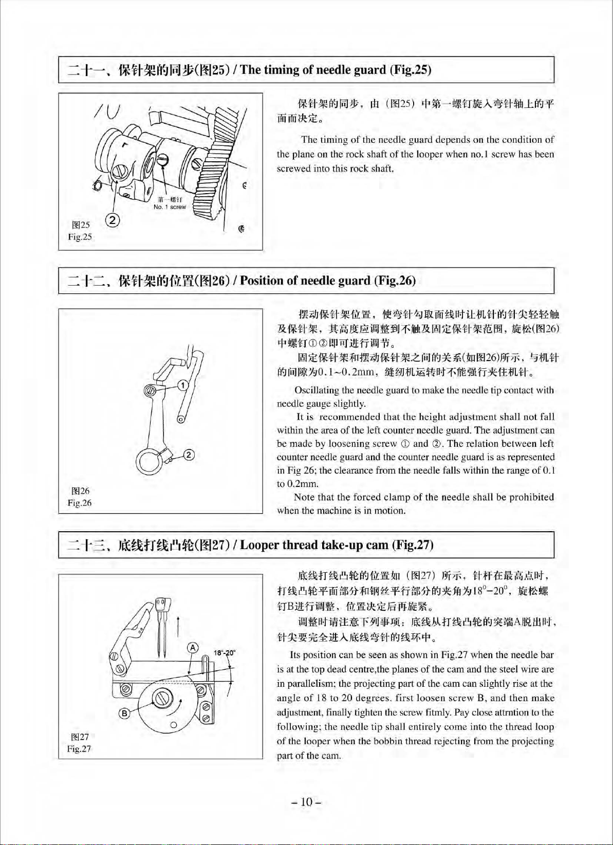
~R~~~Rm*m,
~~*m~~#~n~#Tfi,
~~~~•~.
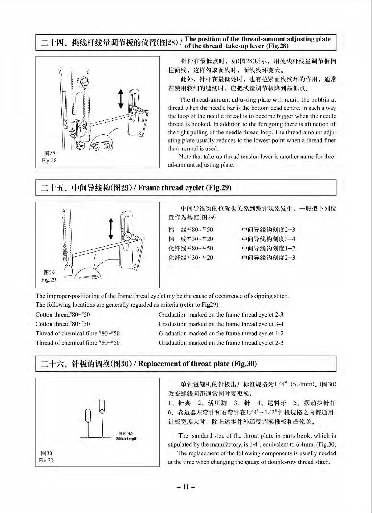
RfflftMff~~~Rm~~~
~'!l:a:l~o
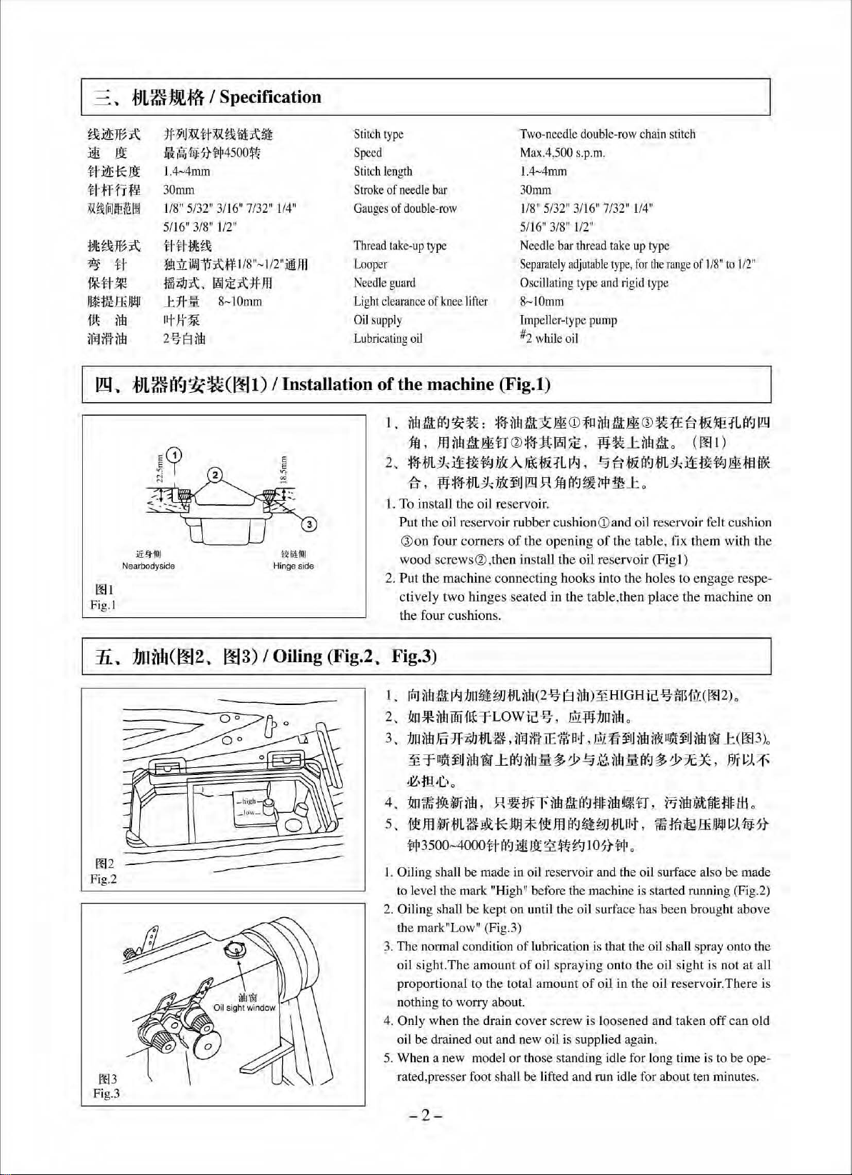
I.~~~ffl~~m*m,
2.~g~~~~·**~~Rm~~~o~*•~·••~~~o
J.Rm*moo.
4.
ftm*fJtOO!lX:Rm*fJL~.
*
•ti
fF
s.
1i1'¥Affl.~·®itQliM
6.~7~~A•~~.am•~~-~M~a•
~~*•~*m~*~~-~.fi~~~~~-~~mm
,
fk:~ftilfo
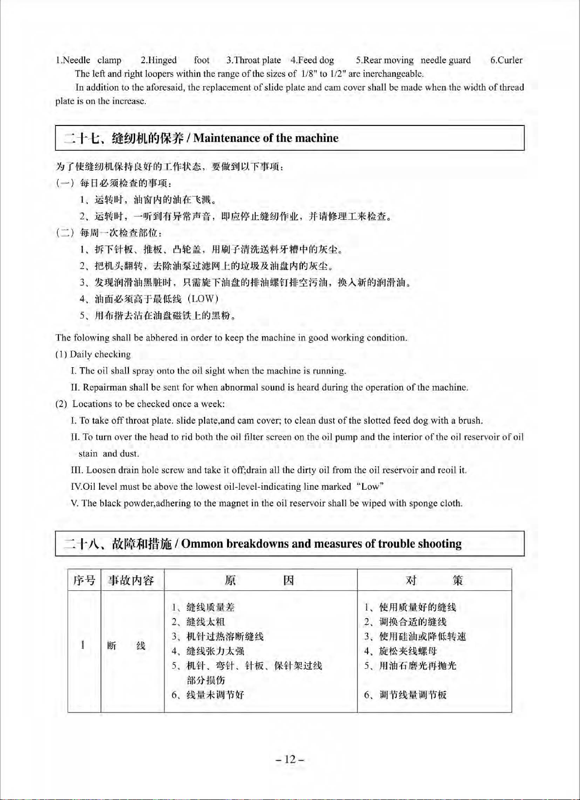
~7•~*~~~-~.
~
~'.JJtfiJII
.~ill
r.JT~~~~~~·3Y!Ne4lt1f~o
o
$S~~*AA·~~Rm*m·•·~~~~~'
~mm~M+~~
o
7.~~-~~·•*m~•**~•~~--~0
7.1
~Lft!.¥~
7.2
J!~;fJU-J-.
7. 3
:ill:ff$f~at
7.4
ti1'Jo!Ri!OC7GAR-.f
8.
;(£tJL:@1
1lf
Jil
rli
~
~IH:IL
irt!~'£1l'ViR
!lX:
:£;
BiJ1141.
0
•
t,
~
#ti.
o
~~'J'•L•itirt!~¥
~
1t
]t
**1-!f~
o
1J
U~!fM. JtJY(~n~rfJ1irt!!lX:ililm-MI,
•~.
o
tJL~jg~~,
~~~~~~
i¥f1rf!lll!f¥)'c
9.
~~
;fJ
L~m~
1
o.
*1L~
~
11.
miE~~:?l:iJ
12.
~·%i
1£~
$#-tQ~~~-.1I~w~m~m~o
13.
~mAAii31~/EAA~ruHWJEE~5tm~o
14.
:iE'Ittiif*fJLff.f·,
15.
IE
~~Ami?:l;t~~M~:fru~f.n:ff~M.l~M~
t6.
~-~i&:il~i&m:*m,
~;ijkff!.]J(1f
17,
**
JL
~Mmf~\.&~~31o
18.
~l'P~'*fJ!lf-1{1=
A
EJ~,
~u~.
II
~.&~:@Am!lX:~~.&-.Ji#Ama'.J:t~~~m:ff~*~:n$1tJ:~*"1'~·
o
ti w Am
F~~Li;tJ;fJL~~~~flf-;flliN~~~:m:.
~&m;frl
A.ol:iltff
ifni
m
~I
1'¥~·
@i
IE~~.&
-
f:N~$fl~;fn~!l&I
!IZ·%i:ill:fi1Jtm~,
iW*mlr5&:1'iJfi~~~mnflio
ii
Jt$
f~Am
-r1u±~
IfF~J.ft~m~!l~
tt*
1fo
o
Am
m:
ff
0
1£ffl~~
ti1J,
i?.,
:tl
l
liWJ~~~;fJL~o
*0-r.IJx.tm!ltrrur:~a'-11%~
&
*¥1.11J
it~-
~
- 1-
Page 3

IMPORTANT SAFETY INSTRUCTIONS
To get the most out
machine
for a long time.
2. Read
4.
5. This machine shall be operated by appropriately-trained operators.
6. For your personal protection. we recommend that you wear safety glasses.
7. For the
9. Tampering with the live parts and devices. regardless
correctly.
Please
Please remember to keep this manual in a safe place.
1.
3. Use the machine after it has been ascertained that it conforms with safety rules/standards
8.
10.
11. General maintenance and inspection works have to be done by appropriately trained personel.
12. Repair and maintenance works
13.
read this Instruction Manual carefully before
Observe the basic safety measures, including, but not limited to the following ones, whenever you use the
machine.
all the instructions. including, but
machine,
country.
All safety devices must be in position when the machine is redady for work
without the specified safety devices is not
7.1 For threading needle (s) and replacing bobbin.
7.2 For replacing part (s)
7.3 For repair work.
7.4 When leaving the working
If you should allow oil, grease, etc. used with the machine and devices to come
or skin
medical doctor.
Repair, remodeling and adjustment works must only
specially skilled personnel,
technicians
Whenever you find a failure
Periodically clean the machine throughout the period
In
following, turn off the power switch
or
swallow any
of
the many functions
addition, keep this instruction Manual so that you may read
of
needle, presser foot, throat plate,feed dog, cloth gude etc.
place
of
such liquid by mistake, immediately wash the contacted areas and consult a
of
or
under the audit and guidance
of
any
of
this machine and operate it in safety, it is necessary
use
. We hope you will enjoy the use
not
limited to this Instruction Manual before you use the
allowed.
of
disconnect the power plug
of
when the working place is unattended.
of
whether the machine is powered, is prohibited.
be
done by appropriately trained technicians
electrical components shall be conducted by qualified electric
of
specially skilled personne
of
electrical components, immediately stop the machine .
of
use.
of
your machine
it
at anytime when necessary.
valid in
or
in
operation. The operation
of
the machine from the receptacie.
in
contact with your eyes
l.
to
use this
you
r
or
14.
Grounding the machine is always necessary fot the normal operation
to be operated
15. An appropriate power plug has to be attached to the machine by electric technicians,
be connected to a grounded receptacle.
16. The machine is only
17. Remodel or modify the machine
safety measures. We assumes no responsibility for damage caused by remodeling
machine.
18. Warning hints are marked with the two shown symbols.
A Danger
in
an envivronment that is free from strong noise sources such as high-frequency welder
allowed to
of
injury to operator
be
used for the purpese intended. Other used are not allowed.
in
accordance with the safety rules/standards while taking all the effective
or
service staft
& Items requiring special attention
-ll-
of
the machine. The machine has
Power plug has to
or
modification
of
.
the
Page 4
t.~R~A~m•.8~~·~·
~~ffl•~~-·~·
•~¥*~mao
2.~~~oo•~m•~-~~
*flllt!fJLo
3.
~i!!i~A~f9ii!t,
4.
~·~A!tf~•
s.~#~~~-M.
il3f~o
6.~~~00-~A~m•.
1.
~~~n•~m•~~~~~~~~~••.m®m~•·~~-~~~•
rr.t
,
-
~
s.~-~
~!H:z~r.
§1~ff*1t~**!OCf*1'FtJLeat
,
~JL·~~at,
m~-=F-m:~t1:E~#~ili.
*
f-'i!
tJL
~
fJf.J
It
~
~m•~m~mttm.m•*~~~.
-~~~~~~••·
9.~R~Mtt.8~tt~-~~.•m~m•~~.
to
.
~n-~n•Stm!l!tt•tta!ll14=~1'.m.
~A~m•.
l:~.
&:1fHolt!.tJL.P.iJI'm~4ht:It13:frU!I11Jd'lt
-
~m¥-f-=F-:~t.A:ti~~~IAJ
§B~•m*m~~.
~•.~•~~m~~-~~
,
tJ
~*·•~#~.
m:m-•m:~tAma~AJM
•
ttm~~-o~•~m•~~
•*wme~tt~**o
::£E:tru.J.::_•W:r
:fru
o
Jm:m-
~:~t.f:EtJL-tt-r:n
0
•~w
~z
m.
t'R*Wtt~
*~·
.
~
0
matt
o
-iii-
Page 5

FOR SAFE OPERATION
~
&
1.To avoid electrical shock hazards, neither open the cover
motor nor touch the components mounted inside the
1.
To
avoid personal injury, never operate the machine with any of the belt cover, finger
guard
of
safety daevices removed.
2.
To
prevent possible personal injuries caused by being caught in the machine. keep
your fingers, head and clothes away from the handwheel, V belt and the motor while
the machine is operation.
3.
To
avoid personal injury, never put your hand under the needle when you turn "ON"
the power switch
4.
To
avoid personal injury, never put your fingers into the thread take-up cover while
the machine is in operation.
5. The
6.
7.
looper rotates at a high speed while the machine is
ible injury to hands, be sure to keep your hands away from the vicinity
during operation.
replacing the looper.
To
avoid possible personal injuries, be careful not to allow your fingers in the rna-
chine when
To
avoid possible accidents because
power to the machine when
or
In
tiling/raising the machine head.
In
addition, place nothing around them.
operate the machine.
addition, be sure to turn OFF the power to the machine when
of
abrupt start
tilting the machine head or removing the belt cover and
of
the electrical box for the
electrical box.
in
operation,
of
the machine, turn OFF the
To
prevent poss-
of
the looper
the V
belt.
8.
If
your machine is equipped with a servo-motor, the motor does not produce noise
while the machine is at rest.
machine, be sure to turn
·g.
To
avoid electrical shock hazards, never operate the sewing machine with the ground
wire for the power
10.
To
prevent possible accidents because of electric shock or damaged electrial camponent(s), turn
power
plug.
supply removed.
OFF the power switch in prior to the connectrion/disconnecti on
To
avoid possible accidents due to abrupt start
OFF the power to the machine.
of
of
the
the
-lV-
Page 6

~1'FMit~$!9i
·················
·······
·········
···
· · · · · · · · · ·
···
···
·····
···············
· · ·
·····
························
· · · · · · · ·
···············
··
·····
-1
- , 7f$Mit!.it.$J1i!
-=
'
ftJflit~$:rjji
~' ;f:JL~~~f~···
1!9,
m~tt-J~
Ji,
:tJnnf:J
1\
'
iii
til)
-t,
mr~l¥-1~7*
!\.,
}(E~I¥-1~1*
fL'
~~:l*-
-t'
ffi
~
-t-'
-t-=,
-t-
-t
#~Ei.I¥-Ji.ffll'il
;f:JL-ftl¥-1~~
,
ffi
[9
' :ili
~
......
........
irti
ii:
il~
................................
.......
..........
JJ!IJ
rWJ
1.l
*'~
?f
1¥-1
...........
.....
................................
······
············
......
....
················
..........................
....................................
=p-
.......
..............
............
.....
a'.J
i)!J
.......
....
.............
..................
..........
...........
.............
i.ml
=n-..............................
=p-
......
.................
..............................
.............
·········
··········
............................
.........
.........
..............
..............
........
.....
.........
........
....
......................
.......
............
.....................
.......
................
................
.......
.................
................................
...............................
.....................
......................
..........................
·····
···········
....................
·······
............................................
...........................
...........
........
....
.......
...
.....................
........
............
.......
...............
.................................
.......................................
.......
......
..........
.........
..........
............
..............
........
........................
······
.. ·········
..........
.................
..........
.......................................
............................................
................
.....
........
..........
....
.....................
...
..........................
........................
......
..............
......
.........
.................
.....
.....
............
................
.............
...
........
............
...
.....................
......
..............................
......
......................
...........
....
................
........
...
....................
................
..............
....
...
........
........
...............
.................
...
............
.....
......
.....
......
...........
.......
....
.....
......
......
. ]
..
-3
. 3
..
. 5
1
2
2
2
4
5
6
6
7
7
-tii,
-t
/'\
' # :ff
-t-!:;,
-tJ\.,
-t
iL ,
=
-t,
=-t- ,
= -t
-=
=-t-=:
=
-t
1!9,
=
-tii
=
-t/\
=
-t-t
= -t /\.'
:i!iM?f-!§#1¥-Jfil.l~
rlWJ
l.ll¥-1
i.ffl]
;fJL#:fO
~-ft
~t~-~¥-J'qn
~-ft:,fo;f:
,
,
,
,
,
~#i¥-Ji.ffll'iJ
;f:BX11JL#I¥-Jfi1.1~
it
JL#
l'
al
f*tt~a'.Jfil.l~
.f:*ti-~1¥-Jti'l::'i!i:
}(Eg&:tJg&[_)~
f:J~g&;f:fg&
r.f:llill~g&~
-ft;f&I¥-Ji.ffli~
~W;tJLa'.Jf!3f
:;t
i!&l$:f01t\'1if!!.
.
................
=p-
..........
.........
.........................
..............
......
a'.J
............
I
illi~
....
..........
..
...........................................
................................
.....................
..........................................................................................................................
i.m]'iJ;fli
....
................
............
1¥-Jf!L'I't
.....
....................................
......................
.......
.............
......
.....
.................
.......
..................
...
......................
..........
........
..........
......
..........
..............
......
.................................
· · · · · ·
...............
....
...................
.....................
.......
............................
......
..............
........
.......
.........
......
..........
...................
............................
............
....................
.....
.............................................................
...
................
..........
............
.......
............
. · · · · · · · · ·
..........
.....................................
........
............................................
...
.............
....
.........
......
.........
..............
......
.........
...............
......
.......................
...
....
........
....
.......................
........
.... · ...
............
.........
.....
................
........
.........
..................
................
.........................
.....
.......
........
· · · · · · · ·
..........
...................
..............
.......
......
......
.........
..........
.......
........
.........
.......
...............
............
............
....
........
..............
.............
......
.......
.........
......
.............
...... 9
.........
....
...
· · · ·
......
.......
...
....
..
...
..
7
8
8
. 9
. 9
10
10
10
11
]]
]J
12
12
*
ftf:-=f-
fj}]-
· · · · ........ · · · · · · · · · · · · · · ·
.....
· · · · · · · · · · · · · · · · · · · · · · · · · · · · · · · · · · · · · · · · · · · · · · · · · · · · · · · · · · · · · · · · · · · · · · · · · ·
- v -
..
· · · · · · · · · · · · · · · · · · · · · · · · · · · · · · · · · · · · - I 7
Page 7

Contents
Before operation ·········· ······················································ ························· ··············································-1
1.Pre-start checks ························································ ························ ················· ······································1
2.0pe
rating instructions-····················································· ········································································· I
3.Specification
4. Installation
5. Oiling ..................................................................................................................................................... 2
6. How to regulate oil amount by means
7. The threading
The
8.
9. Thread ten sion asm
12. Setting-up
13. Adjustment
15. The
16. Adjustment
threading
10.
Presser foot .................................... ....................................................................................................... 5
11.
To adjust stitch length .......................................................................................................................... _ 6
14.
Adjustment
timing
· ··················· ················· · · · · · · · · · ··························· ···· · · · · · · ·························· · · · · · · ························· 2
of
the machine .......................... · ..... ·················· ...................
of
manipulating elements on the face plate · · · · · · · · · · · · · · · · ·
of
needle thread · · · · · · · · · · · · · · · · · · · · · · · · · · · · · · · · · · · · · · · · · · · · · · · · · · · · · · · · · · · · · · · · · · · · · · · · · · · · · · · · · · · · · · · · · · · · · · · · · · · · · · · · · · · · · · · · 3
of
bobbin thread · · · ·
· · · · · · · · · · · · · · · · · · · · · · · · · · · · · · · · · · · · · · · · · · · · · · · · · · · · · · · · · · · · · · · · · · · · · · ·
of
the needle ............................................... .......................................................................
of
the height
of
the heig ht
of
feed dog and needle ····························· ································································· ··········· 7
of tbe height
of
of
of need
..
· · · · · · · · · · · · · · · · · · · · · · · · ·· · · · · · · · · · · · · · · · · ····· · · · · · · · · · · · ········ · · · · · · · · · · · · · · · · · · · · · · · · · · · · · · ...
the presser bar·············· ···········--·····················
the feed dog········ ············ ············································································ 7
le bar ...................... ········· ................................... ······················· ········· 8
..
······· ......................... ·······
....
· · · · · · · · · · · · ·
..
· · · · · · · · · · · · · · · · · · · · · · · · · · · · · · · · · · · · · · · · · · · · · · · · · · · · ·
..
·········································· 7
..
···
..
· · ·-4
..
· 2
··
..
...
3
5
6
17.
Adjustment
18.
The
timing
19. Thread-guiding amount
20.
The
clearance
21. The
22. Position
23. Loper thread take-up ca
24. The position
25. Frame thread eyel
26. Replacement
27. Maintenan
28. Common breakdowns and measures
PARTS
timing
BOOK
of
the needle and looper ..................................................................................................... 8
of
looper
of
of
needle guard ········ · · ··· · · · · · · · · · · · · · ········· ············
of
needle
of
of
ce
of
..
· · .. ·
in
reference to needle · · · · · · · · · · · · · · · · · · · · · · · · · · · · · · · · · · · · · · · · · · · · · · · · · · · · · · · · · · · · · · · · · · · · · · · · · ... · · · · · · · · · · · · · ·
of
the loper·······································································································9
looper and needle ····································································· ··························· ········ 9
guard·
thread-amount adjusting plate
et
throat plate · · · · · · · · ·
the machine · · · · · · · · · · · · · · · · · · · · · · · · · · · · · · · · · · · · · · · · · · · · · · · · .. · · · · · · · · · · · · · · · · · · · · · · · · · · · · · · · · · · · · · · · · · · · · · · · · · · · ·
.. ·.
·························· ······························································ ···························-
m··
······················································ ·································· ···· ····················· I 0
· · · · · · · · · · · · · · · · · .... · · · · · · · · · · · · · · · · · · · · · · · · .. · · · · · · ·
..
· .................................................... · · · ........ · .............................................................
··
· ···· · · · · · · · · · · · ··· · .............. .... · · · · · · · · · ·
of
the thread take- up lever .............. ..............................
..
· · · · · · · · · · · · · · · · · · · ...... · · · · · · · · · · · · · · · · · · · · · · · · · · .. · · · · · · · · · · · · · · ·
· · · · · · · · · · · · · · · · · · · · · · · · · · · · · · · · · · · · · · · · · · · · · · · · · · · · · · · · · · · · · · · · · · · · · · · · · · · · ·
oftrouble shoo
ting ................................................... ................... 12
·· ··
· · ··········
··
· · · · · · · · · · · · · · · · · · · ·
..
··
9
10
10
11
11
..
II
· · · · · ·· 12
17
- V
I-
Page 8
:Jtfl:wH!lt$19l
71
~:
I Before operation
~-~··~-~~~•a.
·
~~~~~m*
•
liff
ri-A
It! ffi;!! N
·
~~
~~ -
•
TiffriA
It!
lJL~
·~m*•~
CAUTION:
To avoid malfunction and damage
• Before you put th e machine into operation for the first time after the set-up , clea
gathering during transportation and oil it well.
• Confirm that the voltage has been correctly se
power supply.
• Never use the machine in the sate where the voltage type is irrerent from the designated one.
• Confirm that the direction
• Operate your machine at the normal sewing speed or less for the flfst month after the set-up.
I,
llbft~*1Jil
2,mB~ft".M~m*~•ft~m~~~#:n~.~fi
3,
1£lfH
JJ~ffltf.J
4,~-~~mfim~~5~.
I. The machine shall not
2. The rotating direction
(View from
while
3. The machine sha
4.
Check, power source, voltage, and phase number to see wheth
plate
th
bal
ance wheel turning clockwise.
of
the motor to be use
•~·••••~.
iE
~~ , :fill~'~
~l'l!
ffi~*•••#~ffi~
J;1
1
1J
~
:1!
N
~-~n.m
l~Mf5~
~Jf
~ -
~
Ji
be
of
the balance wheel, when the machine is started running, shall be
e right side
ll
be under operation at less than 4
m~~~=
-~~•M•~~~-~~.
It!
VJlt~
~
:1!
N
lHiffJ
o
- •.•~~m*m
iE
1iffJ
o
•@~iE~~-riE~~~r~~
of
the machine, confirm the following:
t. Confirm that the power plug has bee n properly conn
of
rotation
$o
~, @1~
••
started running until the completion
of
the balance wheel.) A warning sha
d.
of
the mot
~:it
~~~4fi~
It!• .
~
or
pulley is correct.
it1
•4000
ffi&•m,~ffi;J!§iE•
,00
0 S.
P.M
#~~~~~~
.
.
.~~•ft
#i!H7~~H1~!&.
of
oilin
ll
be given
. for the first month.
er they
o
o
g.
in advance
are
in
accordance with the ratings on the
n it thoroughly. Remove all du
aga
.
st
ected to the
in
counter-clockwise one.
inst making the machine run
nam
e
=.
Bl!11li!~·JiJi
I,
tJLcB~~Brt,
2,m·~~~.
3,
fJLBrdu!Ef
4,*~
1'1!~«*
tJLBftUifiJ
5,
«B
~~H
iWi!
-~
•
ll:.FP.
*FP·
.
t.
-rn~
I Operating instructions
J:m-
=f-:J.&¥1
J#tf.J~$o
8 ~N
~Am~ff~-~
7t~t.l~~m
~r•tt~tr.J
a~t~,
o
•a
.
~~~;!tE:t:F-iN®
o
l'l!~m
~~•••~
:ili
~tfam~$~,
- ·~~
"V" m&#}. f
Efmt-t:ili.
6,
cm&m•
I.
Do
not put your hands under the low
2.
Do
not put your fingers into the thread take-
3.
Only when the machine stops can you turn the balance wheel by hand.
4. After the motor
have the machine tilted unless is stop
5. Keep away from the balan
6. Do not sta
&~m
rt
running the machine during mounting
a~
.-~JF~m•
sw
itch being turned off, due to inertia, the motor will continue to rotate for a while. Be careful not LO
ce
wheel,
V-b
o
er
part
of
up
s.
elt, winder and the mot
the needle when the machine is runnin
lever cover when the machine is running.
or.
or
replacing the
belt cover, finger guard, etc.
-1-
.~~
l!
g.
·~•·*~
l;1
Jm.
t!!~WrE*
ll:.
ft~~•
•
I!!i:tfx:~tE
Page 9
t1Li~1l»A~
~~~~
~
)~
~~*It
#fffi~
:«
tt
iitl
ie
~~~~J't
~
tj
i*
#WJ
~fN;ffi}l!ll
i
tt
~
ilflilt~
I!Y
..
1H
Ri
l.4~4m
3
1/8" 5/32
1t'HU
5/1
fi·H~t
-
~
i
1fi
J:::1Hi
ntJl
2%8
:lJLI~l'l{]~~(001)
jlf!fflll
Nearbodyside
I Specification
tJ~
tf-~
1Jj4Jj;Jtl1jl4500~
m
0mm
" 3/16" 7/
6" 3/8"
~
!l!:ftiJWi'i J:\~ 118"~1/
741~\
'
rei! ~ ):\
~
ilir
001
Fig. l
~UiJ:\!ii
32"
1/
4"
1/2"
2"jl!iffl
*
ffl
8~10m
m
/Installation
t~
\ii
l(l
Hinge si
de
"S
tit
ch
type
Speed
Stitch
leng
Stroke
of need
Gauges
of double-row
Thr
ead
take-up
Looper
Needle guar
Light
clearance
Oil suppl
y
Lubricating
of
the machine (Fig.l)
I .
th
le
bar
type
d
of
knee lifter
oil
M:at~~-=
ifi,
fflila:at~tr
Two-need
Max.4,500 s.p
1.4~4mm
30m
118" 5/32"
5/16" 3/8"
Needle bar
Separately adjutabl
Oscillating type and rig
8~
lmpeller-t
#2 while oil
·M·~-
Q)•:Jt
2.am~~-~~A••~~.
~. w•·~~~~fljfi~-~-
l.
To install the o
Put the o
Q)
oo
four
wood screws
2. Put the machine conn
ctively two hinges seated in
the four cushions.
il
reservoir.
il rese
rvoir rubber cushionOOand o
corners
of
the opening
<I>
,then install the oil reservoir (Fig I)
ec
le doubl
e-row chain sti
.m.
m
3/1
6"
7/32"
1/4"
112"
thr
ead take
l0mm
ype
pump
OO
~M:at•®
re!J/E,
up
type
e
type
,
for
the range
id
type
fi}~J:M:ato (~I)
~~•~m~~•~•m•
l:o
il
of
the tabl
ting hooks into the hol
the
table, then place the machine
tch
of
1/8
"
to
1/2"
·~~-m~~~
reservoir fe
e,
fix them with the
es
lt
cushion
to engage respe-
on
1i
..
JJnilfJ(002
002
Fig.2
003
Fig.3
..
003) I Oiling (Fig.2
..
Fig.3)
1.
lf:iJilb:at~1Jli
2.
-
~o
*
3,
)
JliM
~
~·~ilE
4.~---~.
s.Rmam•~*M*Rm~~mm~.
tJI•3
500-4000tl
l.
Oiling sha
to level the mark
Oiling shall be kept on until the o
2.
mark"Low" (Fig.3)
the
3.
The normal condition
oil sight. The amo
proportional to the total amount of o
nothing
4.
Only when the drain cover screw is loosened and taken
oi
l be drained out a
5. When a new
rated,presser foot shall be lifted and run idle
~~
JJmM
(2"%8 M)~lllGHic
nn
ffff
fl
.Ff
Low
ic
-~,
J§JF~tJm~,
wHJtlE'ffi"Ht
~l:
~MM
~~~
RWm~M:at~mM•tr.
·a'oJ:ia!Jt~f!<~
ll
be made
to
worry about.
in oil reservoir and the oil surface also be made
"I-Ugh
'1 befo
re
of
lubrication is that the oil sha
unt of
oil spraying onto the o
nd
new oil is supplied again.
mod
el or those standing
-%ffl
m w
»oilE
0
,
m~H~IJiltmlnY!¥1JM~
~MM~·~~*
•msffi•~•*
I 0
7H
ijl
0
the machine
il
is
started running (Fig.2)
surface has been brought above
il
in
the o
il
idl
e for long time is to be ope-
for about ten minutes.
H
!L(I¥J2
)o
J:
(003)
.
·~~~
~ilERftmllio
ll
spr
ay
onto the
il
sig
ht
is not
at
all
reservoir. There is
off can o
ld
-2-
Page 10
,\,
iiii~Sitkl:ifnlilCm4)
I
How
to
regulate
oil
amount
by
means
of
manipuJating
elements
on
the
face
plate
(Fig.4)
~~M~~~-.
~J~.
~ft(:t'~
t
mark
you desire. Otherwise, max.
wili~ff~fffi~a-t,
~-: ~~MA
.
To
turn oil-amount adjusting pin to regulate oil amount
hread take-up cr
of
adjusting pin move s to the thread take-up crank as near as
illl
ti!W
n'i
Oil adjusting pin
'rn
Graduated mark
0
;-
Cltl]R,.
~
III4
Fig.4
--1:;,
Wt!f.J~~(005)
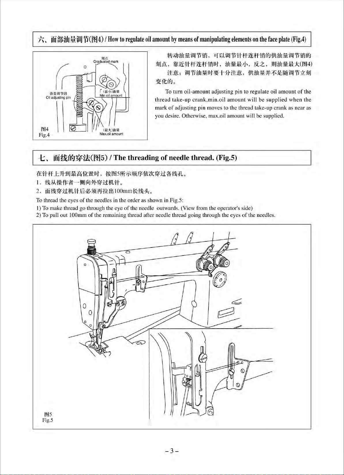
~~ff~*~•amft~.•oosm~•~•~•M3~R.
1.
r~
Mt*1'F:t--11Jl1JrfiJ9~~M;tJL~
2.
ilfi~~M:fJL#
To
thread the eyes of the needles in the order as shown in Fig.
I) To make thread
2) To pull out 1
ni~·~flffl[l:f::llOOmm-!*~ik.
go
through the eye
OOmm
of
I The threading
.
of
the needle outwards. (View from the operator's side)
the remaining thread after needle thread going through the eyes
of
needle
thread.
S:
~~~~~ff~ff·~~M~~~-~
MflH
r!u
J~.
&z.
!J!IJM
!ift:k(i¥14)
a-t
W+#~
ank
,min .oil amo
• .
~M
·*~~
unt
will be suppli
oi
l amount will be supplie
-~~
ed
d.
(Fig.S)
of
the needles.
~~
of
the
when the
ms
Fig.5
- 3-
Page 11
J\.
~
fi.t~l'(.J~i!(006
~
007) I The threading
of
bobbin thread
(Fig.6~
Fig.7)
Ji.H!Ht<
I
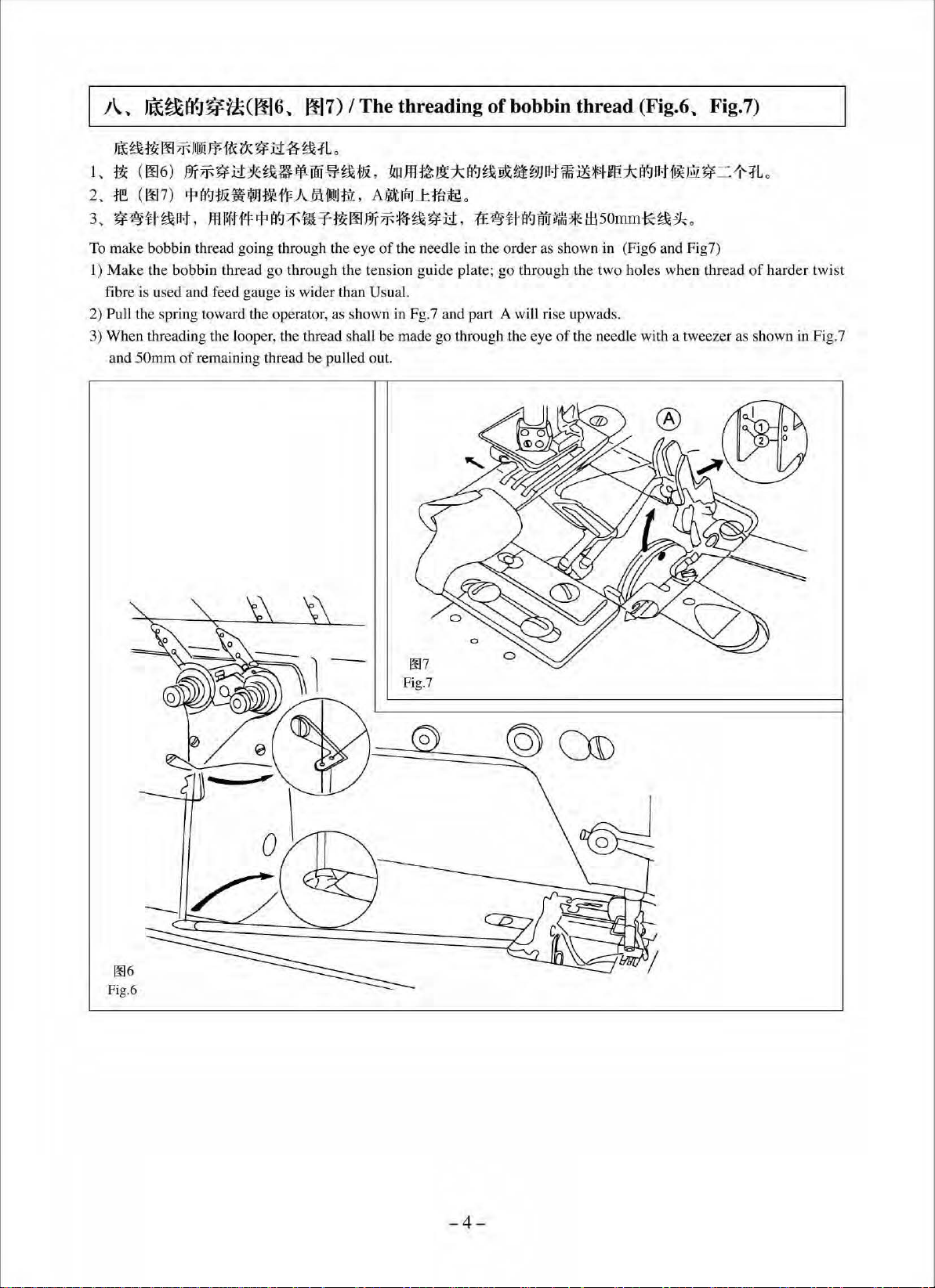
.~(006)m7r-~:tt~~••oo~~~
2.
~e
3.
~~tt-~at,
To make bobbin thread going through the eye
Make
I)
fibre is used and feed gau
2) Pull the spring towa
3) When threading the looper, the thread shall be made go through the eye
and
00
7f-
I1IDl
Fff"&
(X~
(
00
7)
r.p
~ ~&
.liYHlVd'F-
Jfll)f.tflj:r.j:I~/Fli-Tt?iOOJ-1JT
the bobbin thread go
rd
50mm
of
remaining thread
:i1
~~:fLo
.~m~~*~
A
1A
imtlm
, A
il.t ~ J:
iii
7f-
¥-f~~:tt.
of
the needle
thr
ough the tension guide plate;
ge
is wider than Us ual.
the operator, as shown in Fg.7 and part A will rise upwad
be
pulled o
ut.
lt9
~~-~
o
1:E~tl-
in
the ord
a~iW!tffil
er
as shown
go
through the two holes when thre
Mm
mMm*
=>IH
il50
of
the needle with a tweezer as shown in Fig_7
~MM@•=
mm*~#-
in
(Fig6 and Fig7)
s_
o
~R
ad
o
of har
der twist
-4-
Page 12
n~
~~~~(008~
008
Fig.&
009~
0010) I Thread tension asm.
(Fig.8~
ITif
g:
.B*
1J
l'f.J~
ag&*1JI¥J~~(0093f
a
oo
g&
ai:J
=rc ~ (
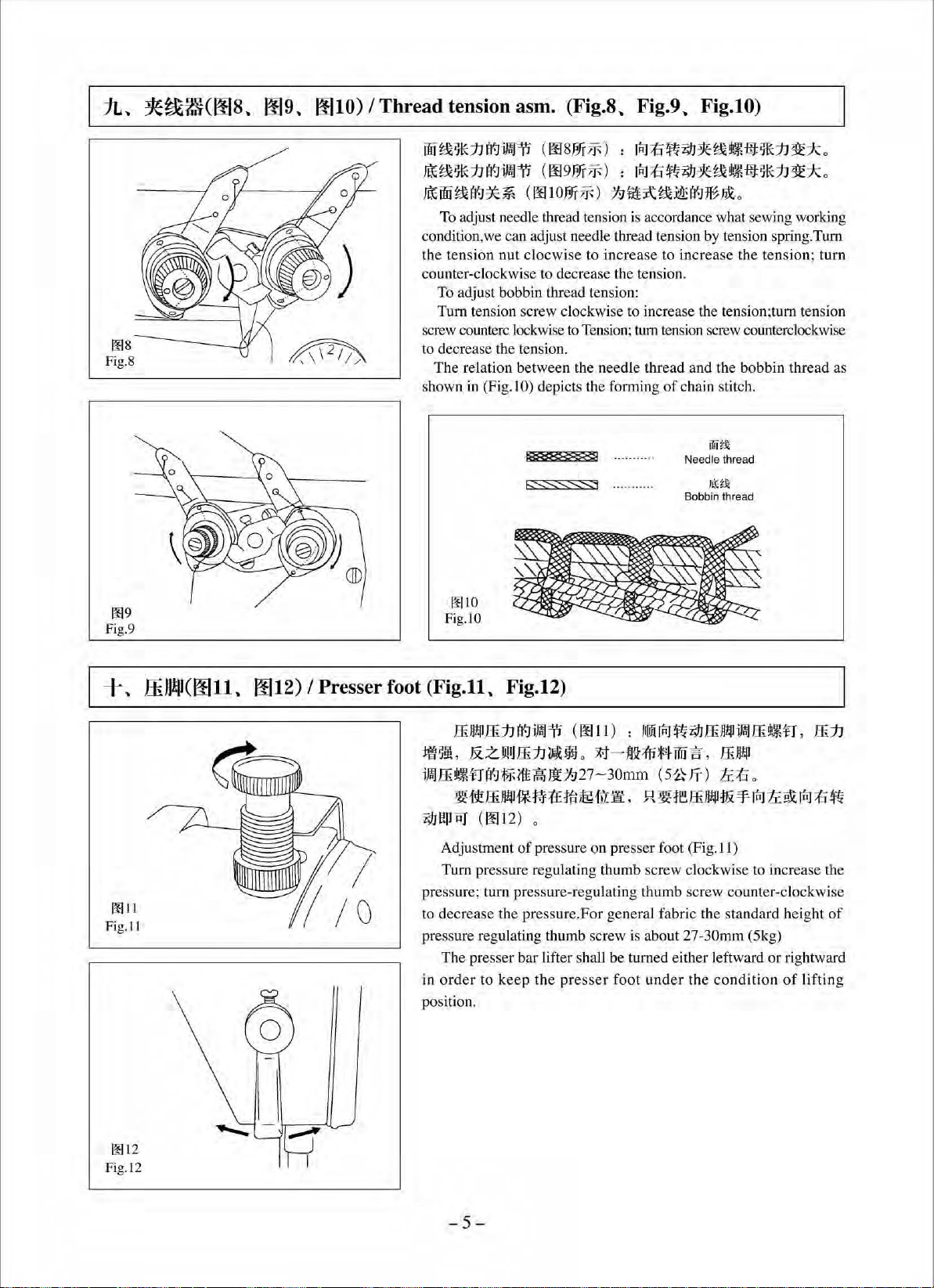
To adjust needle thread tension is accordance what sewi
condition,we can adjust needle thread tension by tension spring.
th
e tension
counte
r-
clockwise to decrease the tension.
To adjust bobbin thread tension:
Tum
tension screw clockwise to increase the tension;turn tension
screw counterc lock wise to Tension; tum tension screw counterclockwise
to
de
crease the tension.
The
relation between the needle thread and the bobbin thread as
shown
in
(Fig. I
(
00
8
3r
oo
1 o
1rr
nut
clocwise
O)
depicts the forming
7F) : rJiJ
7F): rJiJ
7ft )
to
Fig.9~
;(:]
tffl
;(:]ft
1:7
t4
j\;
g&
incr
ease
to increase the tension; turn
of
Fig.lO)
Z9J
*
g&
it'-
flt
~*
1J
1f
* o
Z9J
*M•~*:h1f*o
~
a~:J
*
nt
0
ng
working
Tum
chain stitch.
jTjjtl(
Needle thread
/If:~
Bobbin thread
009
Fig.9
+
~
ffiJJ!II(OOll.
0011
Fig.
II
0012) I Presser foot
1¥1
10
Fig.lO
(Fig.ll.
ffi
*~·
im!ffi!lt'-nfii:J;f'f><lf.ll
~~ffiJI!fJ§M~M~mft.
i;IJl'!PiiT ( 00
Adjustment
Tum
pressure; turn pressure-regulating thumb screw counter-clockwise
to decrease the pressure.For general fabric the standard height
pressure regulating thumb screw
The presser bar lifter shall be turned eith
in
order
position.
Fig.12)
J~
ffi
1J
a1:J
ifn]
i'J (
00
I I ) : )l
&Z~ffi:h-~o~-fi~MW~.
H£1:727-
12) o
of
pressure on presser foot (Fig. II)
pressure regulating thumb screw clockwise to increase the
to
keep
the
pres
ser
im
[Jij
~
i;IJ
ffi
Jl!fJ
~ ffi
!t'-
n , ffi
ffiJI!fJ
30mm
(
5~
JT)
ti.;(:]
0
R~WffiJI!flfi~~~~rJiJ;(:]ft
is
about 27-30mm (5kg)
er
leftward or rightward
foot
under
the
condition
of
lifting
1J
of
0012
Fig.l2
-5-
Page 13
+~~
1¥113
Fig. l3
-r
-
~
!ff~I
:
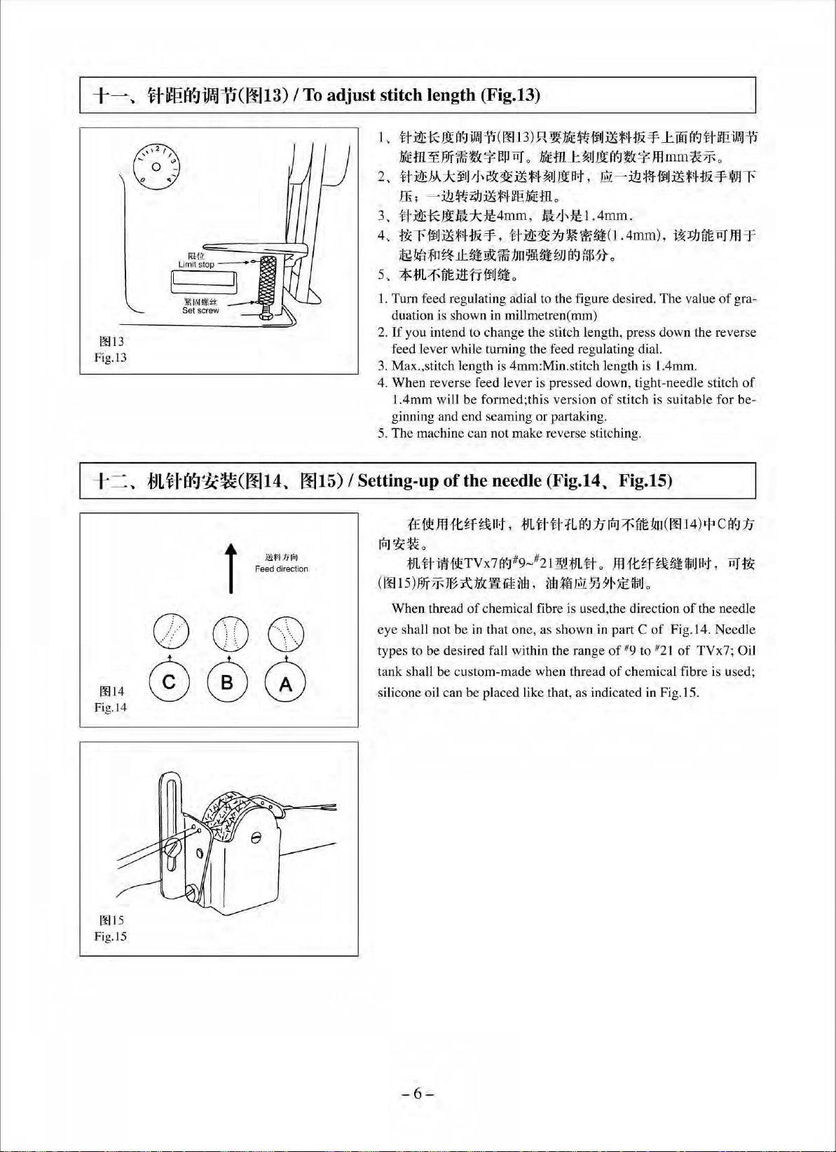
Ht{]WilCOOI3)
I
To
adjust stitch length (Fig.l3)
1 ,
tt~
•m~m••*•~·•m~•J3ti¥-1B*mmma~
2.
#~M*~'J'J'a~lti*I-~
lli
3,
#~¥:};{.ft:k~4mm
4,
~rfiiJJli~H~-¥.
,g
5,
**
I. Turn feed regulating adia l to the figure desired.
duation is shown
2.
If
you intend to change the stitch length, press down the reverse
feed lever while turning the feed regulating dial.
3.
Max.,stitch length is 4mm:Min.stitch length is l.4mm.
4.
Wh
1.4mm will be formed;this
ginning and end seaming
5.
The machine can not make reverse stitching.
f}L!ff(J{J~~(0014~
0015)
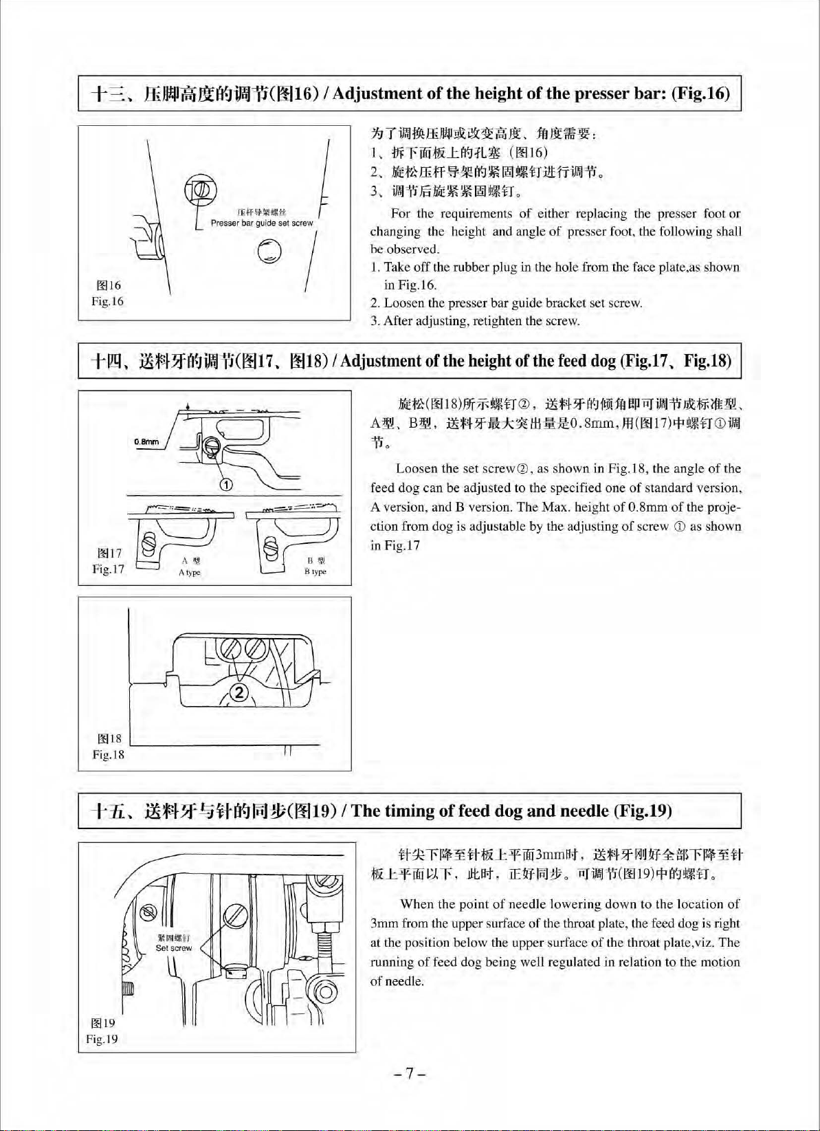
I Setting-up
*
J3t
1¥-1
oo
i1 (
;
-.ill~
#J
:ili*4
M:J
~n
~
_
u-J.ihx
JL::fnt
llH'Tfi
'J
in
en reverse feed l
of
the needle
oo
13)
.R
~
PJHHi
iJ
*
*4
f~
=¥-
1:
ffii
a%i· rm
_
~
.
J
/Jt
flit , mz-
.itl¥-ffj~**'-f~=¥-¥Al'
iE•tn .
,
IVJ,~I.4mm
#:i!Z£~79~*~(1.4mm),
1m
no
~liHi
&:9
J
(f.]
g-rs'lt
~.
millmetren(rnm)
ever
is pressed down, tight-needle stitch of
ver
sion
or
partaking.
(Fig.14~
.
i:r<~tm~J'!
•
The
value
of
stitch is suitable for be-
Fig.lS)
of
F
gra-
l'l
f
1¥1
14
Fig.l4
Feed direction
l
0®®
000
;(:£it
ffl
ft
~f
~at
,
*JL
ti-fi-:fL
rAJ~~.
*
JLth1HtTVx71'l'>J
(00
1
5)1ifrl'Ff~Jt.Jtx:]!fr£ftil
When thread
eye shall not be
types to
tank shall be custo m-made when thread
silicone oil can be placed like that, as indicated
be
desired fa
of
8
9
~82I~HJL#
'
chemical fibre is used,the direction
in
that one, as shown
ll
within the range
l'l''J
:17
lnJ
::f
fit
'!lo
(
.
JlHt~f~~iiJI
illl~L\!Z§J5'
~
)i::lli
l]
0
in
part C
of
8
of
of
8
9 to
21
chemical fibre is used;
in
Fig. IS.
00
14)
~
C
1'1''1
JJ
Jflit
,
~t:&:
of
the needle
Fig.14. Needle
of
TVx7 ; Oil
Fig.l5
-6-
Page 14
+ =
~
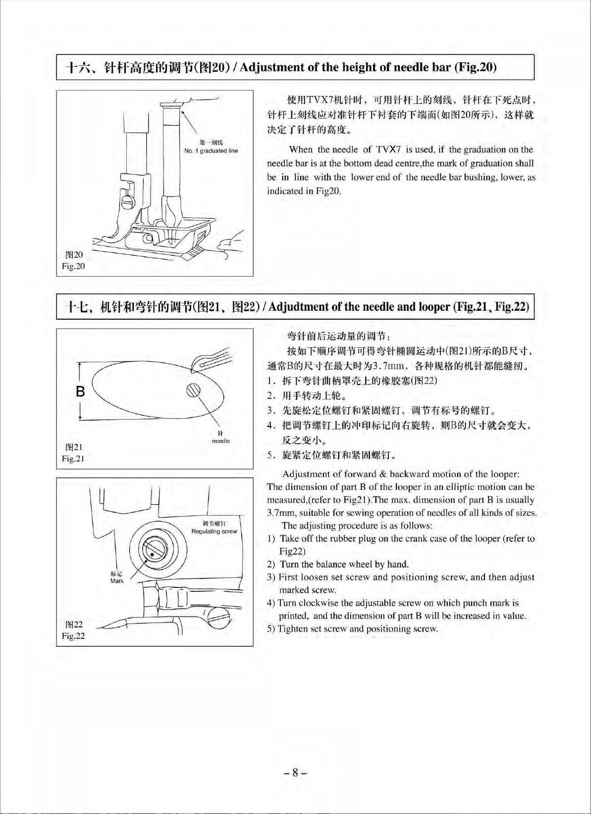
ffiJJ!Pf.lilll'miJJi1(0016) I Adjustment
of
the height
of
the presser bar: (Fig.16)
0016
Fig. l6
+lm~
~~...j-7f(t9iJW]l(0017.
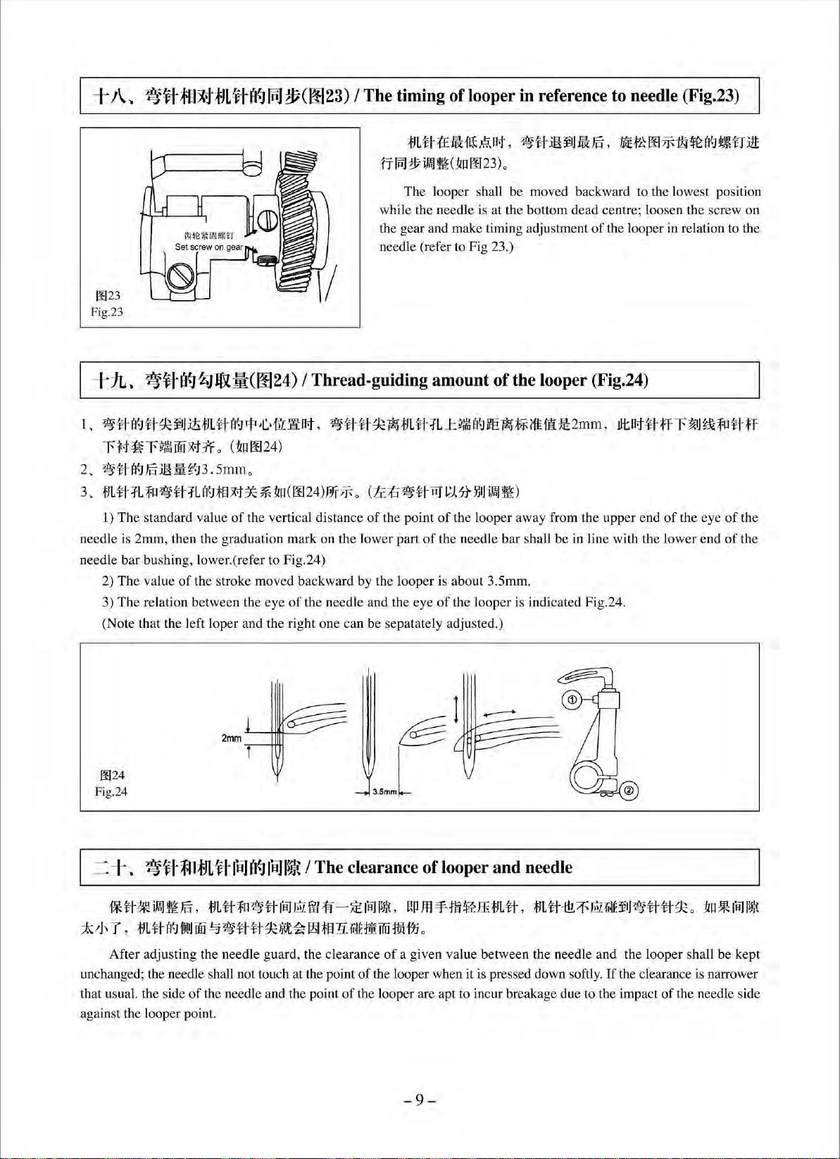
0018)
~~-
00
17
Fig.17 A type B t
~
~
I
Adjustment
·:.
-
B'W
ype
~T-~ffi-~~~···
1,
mrffii;f&J:a1:t
2,~~ffiff~~~~~~rt*fi~~
3.
ifol~m~~~ffiil~~n
For the requirements
th
changing
be
observed.
1. Take
in Fig.16.
2.
Loo
Af
3.
e height and angle
off
the rubber plug in the hole from the face plate ,as shown
sen the press
ter adjusting, retighten the screw.
of
MEt'~
(
00
A~.
B~ • .ili!¥47ffk*~'H
L
~
er
bar guide bracket set screw.
the
height
I8)P.Ji'7F~~rt
-~WW:
(OO
I6)
o
o
of
either replacing the presser foot or
of presser foot, the foll
of
the
feed
dog
(Fig
CZl • .ili!¥4 ?fa1 ftJi
l
Lil:~0.8
1ft
I'.!
rnm,ffl(0017
i'io
Loosen
dog can be adjusted to the specified
feed
A version, and B versio
ction from
in Fig.
the set
screw
Q),
n.
The
do
g is adjustable by the adjusting
l7
as shown
Max. height
in
Fig.l8,
one
of
of
0.8mm
of
owing shall
.17.
Fig.18)
P
r.iJ
iml=il
JiX:$-Fl'ttm!L
)
rp~rtCDiml
the angle
standard versi
of the proje-
screw
(i)
of
the
on,
as shown
+
.Ii
~
00
19
Pig.l9
lli~-+~
~INIJI!'ff
Set
~ltl'l'!l15Jif;(0019)
scr
ew
I
The
timing
·
t&
1:
if
3mm
at
the position bel
running
of
needle.
of
H~rlltf-~flt&J::ifffii3mm
w
t;J.
r ,
Wh
en the po
from the upper surface
of
feed d
feed
JJt
not
int
ow
og
dog
,
of need
the upp
being we
-7-
and
needle (Fig.19)
flit
,
iliff
IE~
1\lJ
t11
0
r.iJ
iffii
le l
owe
ring down to the l
of
the throat plate, the feed
er
surface
ll
regulated
of
?f~
IJ~
~ffl5rll$~-¥
11
(
oo
19)
rF
a'~
!1\.~U
ocation of
dog
is right
the thro
in
at
plate, viz.
relation to the motion
~
0
The
Page 15
-t
~\
~
**ff.liltD'>JiJJi1(0020) I Adjustment
of
the height
of
needle bar (Fig.20)
0020
Fig.20
-j---1::;.
~21
Fig.2l
0022
Fi
g.22
it!JflTVX71JLtf-Bt, ~ Jfl#ff
tt
ff
1:
~J
~fill
x.t
?1t
tt
tr
r
tk:
~
T -tl·ff
!i1-$<1
No
fJLftf;ll~ft(f.JiJW'PC0021.
Jt\l
. 1 graduated line
H
needle
0022)
I
needle bar is at the bottom dead centre,the mark
in
be
indicated
Adjudtment
>l};
11{
lin
1lt
B
I .
tlfT~Jtt-~rfll'iiii%J:ff.J~~~
2.
Jfl=f~i'JJJ:~
3.
%~~~~~fl~~~~fl.~11~~~ff.J~flo
4.ffi~l1-fll:ff.J~~~~~~-~.MBff.J,R.~U~~:k
JXZ~Ij'o
5.
-~~~t~nfn~~t~n
Adjustment
The
dimension
measur
3.7mm, suitable for sewing operation
The adjusting procedure is as follows:
1)
Take
Fig22)
2) Turn the balance wheel by hand.
3)
First loosen
marked screw.
4) Turn clockwise the adjustable screw on which punch mark is
printed, and the dimension
5) Tighten set screw and positioning sc rew.
ff.J
~
tft
o
When the needle
line with the lower end
in
Fig20.
of
-tl·
j'jiJ
!§
:iE
~n
r
''Pilr¥
A9
,R.
-t
tE
lil:kBt
of
of
ed,(
refer to
off
the rubber plug on the crank case
set screw a
of
the
needle
i;
b
iii
ff.J
~
ifnl
fi
PI
l~
1':1
o
forward
part B
of
Fig2l).The
J:ff.J~U~,
t-t
~
a9
r
~ffil
oo
(
~~~
TVX7 is used,
of
the needle bar bushing, lower, as
and
11
:
~ttwn
3 .
mn
7mm
, ~ #
0
& backward motion
the l
ooper
max. dimension
nd
positioning screw, a
of
part B will be increased
if
looper
:iEi;~i
!f1
~:Mi
(
0022)
in
an
of
needles
#ff1£r~.~ut,
oo
20
J1fr
:if\)
. ~
¥f
8,.t
the graduation on the
of
graduation shall
(Fig.21.
(
oo
21 )
A"J
fJL#
of
elliptic motion can
of
of all
of
the looper (refer to
Fig.22)
J1fr
:if\
ff.J
1-iB
fiMHJJ
the looper:
part
B is usually
kinds
nd
then
in
B R
-t
of
sizes.
adjust
value.
,
o
.
be
-8-
Page 16
i-
J\
0023
Fig.23
~
~fi·;f:H~f
fJLfti'J{J
lf.l1~(0023)
I
The
timing of looper
m#~•~~~. ~#m~aJE.•~m~cm~•nm
fff5J~imJ~(.t.IIJ0023)o
The looper shall be moved backward to the lowest position
while the need le is at the bottom dead centre; loosen the screw on
the gear and make timing adjustment
needle (refer to Fig 23.)
in
reference
to
needle (Fig.23)
of
the looper in relation to the
i-JL.
1.
~tta~uqc~IJit-tJL-tta~~
-rM-~r~lffiooM1f
2,
~ti"~JE
3, tJLtt:fL
1)
needle is 2mm, then the graduation mark on the lower part
needle bar bushing, lower.(ref
2)
3)
(Note that the left Ioper and the ri
0024
Fig.24
~fi-I¥J~~If(0024)
0 (
1.m0024
:itHII:r.J3.
fo
~~·1L~;f§M5c
The
standard value
The
value
The
relation between the eye
5mmo
of
the vertical distance
er
of
the stroke moved backward by the l
2mm
I Thread-guiding amount
.C
.'1!l::i!:A>t.
~tl·~-qc~m~-:fLJ:!Jffilfi::~ie~~i'f£it:ll2mm,
)
~
.t.to
(0024)W!"Jft
to Fig.24)
of
the needle and the eye
ght
one can be sepatately adjusted.)
o
(ti::tl~tl-
of
the point
ooper
of
the looper (Fig.24)
l'lJ
l;HHJIJimJ~
of
the looper away from the upper
of
the needle bar shall be
is about 3
of
the looper is indicated Fig.24.
)
.5mm
.
JltA>t
-tl·f-T-r~
end
of
the eye
in
line with the lower end
IJ
~fo~-.t:f
of
the
of
the
§t~-•~mJE,
*~T,mt~-~~w~~U#~a~~~~••ffiam
After adjusting the needle guard, the clearance
unchanged; the needle shall not touch at the point
that usual. the side
against the looper point.
mu~~t~-~@00~-~~•,
of
of
the needle and the point
of
the looper are apt to incur breakage due
~m¥m&ffim#,m#~~@·~~uuqco~•~•
o
of
a given value between the needle and the looper shall be kept
the looper when
it
is pressed down softly.
-9-
If
the clearance is narrower
to
the impact
of the needle side
Page 17
-
---t-
~, f*ft~B91iiJ~(0025)
I The timing
of
needle guard (Fig.25)
0025
Fig.25
=+=.
0026
Fig.26
f*ff·~l'f9{!L
it(0026)
/Position
i*tt~l'f.J[l'IJ~.
Ell
(0025)
r:p~-~~trmEA.~tt
!ftltl:fl~->f
ffi'iffiHJcJ:E.
The timing
the plane on the rock shaft
ewe
d into this rock shaft.
scr
of
needle guard(Fig.26)
•~•tt~m•.~-#~ailli~~~m~l'f.J#~&&M
2iH1!:tt~,
~
1,
u:n
CD~
11!1/E1*#~lt:Jm?9J1*fi
~~BJ~
J~Y!JO.l-0.2mm,
Oscillating the needle guard to make the needl
needle gauge s
It
is
recommended
within the area
be made by loosening screw
counter needle guard and the counter needle guard is as represented
in
Fig 26; the clearance from the needle falls within the range
to 0
.2mm.
Not
e t
when the machine is
of
the needle guard
of
the looper when no. I scr
~f.JJJJtfi!ZiffiJ~¥1
an
PI
Jn:
rrifn!Ti.
li
ghtly.
of
the left counter needle guard. The adjustment can
hat
the forced cl
in
J~.M
-
~Z.Iilll'f.J:}C~(:!m0026),P)f;if-,
~~:JJtJLi!i~IJot7f-~~Mff:9E1:HJLfi
that the height a
G) and
amp
motio
n.
dep
end s on the condition
&rnii5Ei*#~ffiEm,
e tip contact with
djustment
~.
The relat ion between left
of the needle shall be prohibit
ew
has been
mff'.{(0026
5JtJ
-
.
shall
not
of
of
)
L#
fall
0.1
ed
=-t-
:::::
.
J(E~fr~8~(0027)
I Looper thread take-up cam (Fig.27)
$;;
~
:J:T
~
8 ~
l'f.J
t'r:JI'J
tH~8~->JZWffiHtwmii->JZrrif~
trB*fi
ifnl~. ttm~!E
~-~~~-~~-~:
0027
Fig.27
tt~~~~
Its position can be seen as shown in Fig.27 when the needle
is at the top dead centre,the planes
ar
in p
ang
le
adjustment, finally tighten the scr
following; the nee
of
the looper when the bobbin thread rejecti ng from the projecting
of
part
*A.f
ij;~-#
allelism; the projecting part
of
18 to
20 degrees.
dle
tip shall entirely come into the thread l
the cam.
-10-
lll (
00
2
7)
lfr
jf-,
tHf
1£
-Ill
f.JJ
;!;i: ~ ,
7
tl'f.J:9EJHY!7
~w••·
t8°-
20°,
mff'.{t~
$;;~Mfi~8~1'f.J~-A~ill~,
B'-J
~J;:f\
9='
.
bar
of
the cam and the steel wire are
of
the cam can slightly rise at the
first l
oosen
screw
B,
and then
ew
fitrnly. Pay close attrntion to the
make
oop
Page 18
- -tn_
~
n.
:hll-~1';.£r:~-m.~m-+•~-~-~;;'*{~
11C~'f
I
~~
IJPJ
1117--"'P'J
~w
c~mzs)
M...EI..
13:
I
The
1
of
the
position
thread
of
the
take-up
tbread-am?unt
lever (Fig.28)
adjusting
plate
0028
Fig.28
~
-t1i.
t=f:tliiJ
~~:#;J(f!l29)
I Frame thread eyelet (Fig.29)
tt-fft£/!fij;,.:.\01",
ttW~.~#~-W~M.
~*
·
~fft£&~~~.~~~-oo~~~~~m.
«Rm•&~amM.
The thread-amount
thread when the needle bar is the bottom dead centre; in such a way
the loop
thread is hooked.
the tight pulling
sting plate usually reduce s to the lowest point when
than normal is used.
ad-amount adjusting plate.
m:
fill
tt
1-tJf~#80-
1{.;-f~#30-#20
of
the needle thread is to become bigger when the needle
of
Note
that take-up thread tension lever
1ft
fal
~~¥!1EI'.J{
1'F:Y9
~lft(0029)
~#80-#50
~#30-#20
#
50
~o(002
8),1Jr~.
00~~~~*0
Jfl1j~~ff~itiAI'TH.!it§
a~
~re~•~~-~~-~4
adjusting plate will retain the bobbin
In
addition to the foregoing there is afunction
the needle thread loop. The t!U'ead-amount adju-
is
another name for thre-
l'
tJ'f-tl!**~'Jll;j~tf-:EW.ftt~~.
~~=t
J
al~~~~'Jlt2-3
1ft
i
hT'il'~~~Jlt3
1ft
l
ill.'i)<~iiJ~
rp
IBJ.'i)<
J.rlt
1-2
~iiJ~Jll2-
o
a thread fin
-
M:reBIJ.fft
-
4
3
at
of
er
0029
Fig.29
The improper-positioning
The following locations are generally regarded as criteria (refer to Fig29)
Cotton
Cotton thread#8Q-#
Thread
Thread
-
-t
0030
Fig.30
thread#
8Q---#5Q
of
chemical fibre #
of
chemical fibre #
,\,
t
l·:fit'f.J~~(f!l30)
5Q
of
the frame thread eyelet my be the cause
Graduation marked on the frame thread eyelet
Graduation marked on the frame thread eyelet 3-4
8080-
#50
#50
I Replacement
Graduation marked on the
Graduation marked on the frame thread eyelet 2-3
of
lft-tt-~~tJ
&~~.~lal~r:!lB!'~II'IJM!fiJ!~:
1.
tt-:'.IE
6,
Off
:iti
tt-fi m !Jt*
#~liill'f!
Stitich length
The sandard size
stipulated by the manufactory, is
The replacement of the fo
at the time when changing the gauge
of
throat plate (Fig.30)
La'.J
2.
tt.ffin~
fi
ft
Vf
t
~
Hot
,
r¥f-
occurrence
of
skipping stitch.
2-3
frame
thread eyelet 1-2
tUJi:±l
/:f>"FiftJ!i'.~:YiJl/
3.
# 4,
'_fll
:tJ
~tj-1:£
1:~ ~ f45'~:ili
of
l/
8
II
-1/2
!fi
V~H!MiHli
the throat plate
1/4", equivalent to 6.4mm. (Fig.30)
ll
owing components is ususlly needed
of
4" (6. 4mm)o (0030)
ili~Hf
II
tf-
in
double-row thread stitch.
s.
~i;IJ:fll#tr
fi
~
Ji!.~
Z
I*J
ljj):@}ij o
;fo
8 ~
iT£
o
parts book, which is
-11-
Page 19
l.Needle clamp 2.Hinged foot 3.Throat plate 4.Feed dog 5.Rear moving needle guard
The left and right loopers within the range
In addition to
plate is on the increase.
=
+-t:;.
~T~•mm•M~~~I~~~.WR~~~-~:
(-)
~B~·®l~~a"J¥J1if:
1.
:iE
the
aforesaid, the replacement
~~fJLB9f*ff
~~at
,
itl1
wr
rJg
I Maintenance of the machine
a'-1
nil
f£~ ~.
of
the sizes
of
slide plate and
of
1/8" to 1/2" are inerchangeable .
cam
cover shall be
made
when
the
width
6.Curler
of
thread
2.:iE~at.
(= )
~Jffj-{j(;f.~§$11l:
1.
m~~•.m•.
2.
mm~~-.
3.
~~~mMm•at.
4.
itllrm~·%i~rnlftt~
5 •
!lH
The
folowing shall
(I)
Daily
checking
f.
The oil shall spray onto the oil
U. Repairman shall be
(2) Locations to be checked once a week:
1.
To take
II. To turn over the head to rid both the oil filter screen on the o
stain and dust.
lll. Loosen
IV.Oil level must be
-
~~~~m~~. ~~w~•m~~. *••~I*~•
8~~.
~~M•M•~~a"J~a&itlla~a"J~~.
R••~itlla~mitll•nm~Ritll.•A~af.J~mitll
(LOW)
IH~~
i~
.:(£
itl1
a
fttH~
~
be
abhered in order to keep the machine in good working condition.
sent
for when
off
throat plate. slide plate,and
drain hole screw and
above
the lowest oil-level-indicating line mark
m~~•~mM~~~~~~.
a'-1
J\U5t
•
sight
when the machine is running .
abnormal sound is beard during the operation
cam
cover; to clean dust
tak
e it off;drain all the dirty
.
.
of
the
machine.
of
the slotted feed
il
pump and the interior
oil
from the oil reservoir and reoil it.
ed
"Low"
dog
with a brush.
of
the oil reservoir
of oil
V. The black powder,adhering to the magnet in the oil reservoir
~
+A.
FF-5
I
t&~Jiif;Utff1/t§
-~1"1~
~
tl
I
Ommon
breakdowns
)]{
I,
-~Jm:ji~
2,
-~::k.m
3,
fJL.ftM~iWitlf·~
4,
•tl*:h::k5!11
5,
,j:JL.ft.
$7t1J.
6,
~if-*iJW'n~
~#.
JHjj
#fli.
and
ffil
t~#~M~
-12-
sha
ll
be
wiped with sponge cloth.
measures of
I.
2,
3,
4.
5,
6,
trouble
~Jfl
ifn]~-€J:@:af.J·~
1:!1!
11iif'~~tlt~-ffJ:
ffl
i!Wi'i
shooting
X1
mi:il:~i't'>J·~
JfJ
1if
itl1
!!X:
ilH
1:i'
~
ft
~:ltl:
iffiJ
Wi
I~~~~
-
PHII/t7't
i'if&
Page 20

2
~t
~
ffij~Jmi#
I '
2.
~~liJEtl·
3,
1!1! m 1-t
J-f ~
4 •
1\f
m
~
!lXJf
o-t
l'l/;j
~~Eft
~~Bot
a{]
HJ6
t t
1,
if.l
~~H
2,
iJiiJ
~
3,
i
mltl:fJ
4,
tLH.Qi~
lffili'J
5,
iml
~
6,
~
1!E
7,
~1f-f*H~~fl!J!l!llmiV
~~IEr!ff!
8,
~:m:~~~~~
I,
;}t(J:~iii~liJ~#I,
2,
~1tti(E~
3,
Wifi&~5!ii~~~~~:n
4,
l&
1!1!
)fJ
1'
2,
llitfli~il
3,
1t
ffl1-t~f~
I ,
fl$f!i~il
2,
1tffliE
~lf5l
:li
'4f
f;f· !§
;fJL
tt
a~
fa]
~t
LH I
WhJ#i'f/;j
~a~
·
lmiV
rw
m:irn~ ~:it
;f}i
1ft
I
RJ
J.'lf
~
ti:J
~
ffi:
1l
;fJLtt'!i: ~ J!:
~
lE
T6H
:iEliffl
2~lt
8 $M%'0 ~
1tt~.iH~~f~
iE
ilH
;ll-N
IE
Ttfil
ffl
AI.J~1Lft
iili
5
3
4
~~~~
Wf
~
~
#
~
1 '
iii
~~g~jJ
:k$
2,
/i£g&5*:h
3,
!i~:k
4,
9='
5,
ffis
6,
#t&
1,
YL#>hJ
2,
lZi
3,
ffi
4,
-f*#~
5'
iii~'HE1JJ:J:5lii
6,
:tJLttJ.cm
l,
~~H~1J:i:J:5!ii
2,
~ ~
3 , ~ J:J:
4,
ffi~l
::l.c$
m
ftij
-'iHJW~
g&
:ff~Jiim!
*4
;fll;fJL
!W
~
:fr~8$~~[ff]
~iHb't
ffi1J
~
ft
~
'!i:
~
1f I
:fl
iEJ*M
115
:k
5!ii
ffi:
tl
~~IE
if~
1!l'1t
[tiJ
!V
EJ
1m
tlf
Jj(
1J
I
EJ
fW
1iffJ
~
lETifA
I,
ME~
1if
~~H~
2,
1tt~
~~
3,
lffil~:k
-15-
4,
iml
~
1ft
5,
iJiiJ
~
~ii.
6,
1!1!m#:rL
I ,
iffll~,fJL
-
H
2,
if.)
~
f
iJ
3,
ffi
n~?L
tJL#
9='
·C.·~-3&
4,
l&
1!t
f*#
5,
J.&:f'~
WI
~'HE
6,
1!1!
Jfl15-
:iW:
L
ll>tft£~~'*1J
~JHY.
H~::h
2,
ill
fiif~"TJ
3 ,
T!lf
~
~J:J:
4,
mEt~ifnlffit~n
~~
-et
~~
9\.~ffl:
;fJL
tt
I
RJ
Ji'f-
~ ~
j!J/;j
11L
'i!l
iJ3Ji11tH~
:k~trtoc
FnJ
ill
tJ·tocfLa~
.
~
1
¥-H
ffi:
rp;t:.
!L ~ ;fll
:'lt
1J
~
fJL
tt
~J}Ij~}ij;
,
,
ft
;f!:
lllJ
~
~;lHfi
Wt
•13
lffJ
:!9
-13-
Page 21

No.
Break own
Cause
Measures to be taken
2
Therad
br
ea
kage
Skipping
stitch
I Poor thread quality
2 Thread being too
3 Fusing thread due to high
at
temper
caused by machin
operation at high speed
4 Tension being too
Br
5
lo
needle gua
location
6 Failure to adjust thread
amount
!.Skipping stitch
thread (leaking
due to the loopers
hook the
ure
eakage
oper, throat plate, and
of
need1
thi
ck
of
needle
es
hi
gher
of
needle,
rd
at the
thread guide
of
needle
of
two stitches
fa
ilure to
e thread)
1.
Quality thread to be used.
2. Rep
lacement t.o be made
3.
Silicone oil to be used a
4. The tension nut to be loosen
5.
Fir
st grinding with oil stone and then polishing
6. Adjusting the thread amount adjusting plate
1.
Adjusting thread-hooking amount
2.
Adjusting clearance
3.
The
timing
of
needle
4. Adjusting the thread -amount adjusting
thr
ead
amount changing conditions.
5. Adjusting the frame thread eye let.
6.
Checking whether the mounting positon
needle is proper
7.
To
see if the locatio n
appropriate way and
regulated in relation to another.
8.
To see
way.
or
not.
if the needle thread threading is
by
an appropriate thread
nd
speed to be reduced
ed
of
bet
ween looper and needle.
in
reference to looper.
of
needle guard is
the timing
of
it is we U
looper.
pl
ate on
of
in
in
a proper
the
an
1) Reference to the above cases I and 2, as to skipping
stitch
of
2. skipping stitch
thread (leaking
needle failure to ent
looper eyelet)
Skipping stitch when thread
3.
of
chemical fribre being
4.Skipping stitch when thread
of
polyester fibre being in use
1. Needle thread tension being
too low.
2.
Bobb
in thread tension being
too low
Sewing thread being too
Twist
3
ed
stitches
3.
thi
ck
4. Improp
S.lmproper
6. Throat plate
er position
frame thread eyelt.
take-up tension plate
of
of
one stitch,
position
bobbin
er
the
in
of
the
of
thread
2) To see
we
3) Increasing tension
4) To see if the threading
correct way.
1)
Using sillicone oil
2) Reducing speed
use
3)
Using needle for threead
I Reducing speed
2 Silicone oil to be used
l. Tightening tension nut
2. Tightening tension nut
3.
Needle of large size to be used.
4. Read
5. Readjusting its position
6.
the eyelet
than norma l on
if
ll
reulated.
ju
sting
the needle
th
e timing
of
of
the needle thread.
of
bobbin thread cam has been
of
bobbin thread a bit highe
of
bobbin thread is
of
chemical fibre.
of
needle thread.
of
bobbin thread.
it
to a proper position.
in
an appropriate way.
throat plate to be used be
e.
r.
in
a
ing bigger
-14-
Page 22

Breakage
4
n
ee
dle
5 Puckering
I) Needle being bent.
2) The op
3) Setting-up
of
4) The problem
5) Needle thread tension being 6) Appropriate nee
6) Need le being too thi
L
2
3 The problem
4 The force on the presser
er
ation
of
feed d
og
being n
ot
well regulated in 1) Needle to
reference to the motion
needle.
of
the presser 3) To make both the centre
foot foot and the
of
the timing 4) The positioning & the timing
of
needle guard remainin g be taken into account.
un
solved 5) Relaxing needle thread
too high.
Thr
ead tension being too
high.
The problem
of
the bobbin thread cam
for thread guiding failing
to be solved.
finish arising from bobbin
thread going through the
parts on
foot being too great.
of
of
th
e thread guide.
of
ck
.
the timing
surface
2) Readjusting the timing to feed
needle.
l . Decreas
thread.
2.
Readjosting of the very cam sa
problem.
3. Surface finishing all the parts on
4. Thming
screw.
be rep
laced by another
of
ce
ntre of the eyel
dl
e to be used.
in
g thread tension, esp. tension
co
unter-clockwise the pressure-regulating
of
proper size.
dog
in res
the hole
of
the presser
et
of
the throat.
of
the needle gua
id
to solve the timing
th
e thread guide.
pect to the
of
bobbin
rd
to
-15-
Page 23

-th-
Page 24

*14~-JVI-
PARTS
BOOK
-17-
Page 25

42
8
6
41
'i
~
:
~
~
0
I
Q
0 0
40
4
--
@
®
~
0
0
0
0
Q
0
;3
3
\
40
-fJJj)/45
@{
@!;ji
~9
~~36
2
37
46
-18-
-
47
Page 26

1,
m-x'l}!liflf:
Arm bed components
%
~
Ref. No.
2
3
4
5
6
7
8
9
10
ll
12
13
14
15
16 GW288
17 GSOI28
18
19 GM242/9
20
21
22
23
24
25
26
27 GM245
28
29 GS045
30
31
32
33
34
35
36
37
38
39
40 GRI461
41
42
43
44
45
46
47
48 GSOI48
14
Part
GQ202/l3
GS0127
GRI823
GKI86
GRI812
GSIOO
GR1757/2
GRI758
GSIOO
GR1458
GRI813
GW287
GRJ814
GS069
GM241
GS012
GM243
GW289
GW290
GS045
GR1815
GS0129
GM244/6
GW291
GRI816
GSOJ29
GW292
GSOIO
GRI817
OS44
GRJ818
GSOIO
GRI819
OSOIO
GRI462
GR1463
GRI464
GRI465
GRI466
GRL916/5
GRI923
"5
No
15
~JL
:J'G
{f!Sftj:
ffii
J(El}i5(:7l(t'-H
J(EtJi:Xll(~
Jr.i
'@"
;fJi
Jr.iiHli~
lr.i
-oo-
t1i
~~
n
iii
l1i
{fl5
flj:
iii1'&'re:
ffr
;fJi
~~
tr
iii
l1i
iJWiHK{1L~
8~~ffi~
8~~ffiti~lJ1~
8~~ffil&~lJ1id~
8~_f:i[ffi~~t~n
~fHlf!J.(
~ ~
~ft
14
'!i
~
~
'¥(!
ff
~ft14!J.(
llff
8~i:Ji1i!Wt-
8~i:Ji
8~i:fif-c~
8$~_f:i['¥(!~
8~
8~1ir~~
8~_f:i[~~l'-H
1lH&ifBf~
~
l1i
~f!i
~
~~
n
14
!fi
~
~
:iE
1ll:
t"
n Screw
~sf!i~t~«n
:
tiU!i
#U!i
~
tftl&fi~'-tJ
tt*li-'il'~
#ft&~~~"n
ffU!iliJl~
tftllifiJl~!lt'-H
tftl&fH~-'F
tiU!i~:te-'F!Iti«H
-ll£*4
41il
r~~
1§
ill!
fli
J(E;ffi
rJ'I
ill!~
t'-
n
1a3ftHnm=~
m:lli
4:1b~
J:~b~
HHIHrtf~!lt'-t
~*'1-tt-il!ir.J:P~HL~
ta?f41il:tL~
r!Hbi~HL~
~ill
-lf:itl~~#c
~~imlli
t3
ill!~
!It'-
:iE
111:
t«
tL~
ill!
~tL~
L
r.J
fflHlf(l
I 4
n
~
11
)
"ffi:it13!lt'-tr
Description
Arm
bed complete
Bed screw stud
Bed support
Side plate
Gasket
Side plate screw
Face plate asm.
Face plate gasket
Screw
Rubber
Cam cover latch
Spring
Spring suspension
Screw
Attachment installing plate
Spring
Screw
Cam cover asm
Cam cover
Cam cover
Spring
Screw
Cam
Screw
Bed slide asm.
Bed
Spring
Screw
Bed
Screw
Bed
Screw
Latch
Screw
Bed
Screw
Bed oil shield
Screw
Rubber plug
Rubber plug
Rubber plug
Rubber plug
Rubber plug
Rubber plug
Folder
Gasket
Screw
plug
cover guide
slide
slide guide
slide lo
ck
oil shield
-19-
spring
1J!
~
--
Amt. Req .
t
2
l
I
8
I
3
2
I
l
L
2
1
(1)
L
4
1
I
(1)
I
l
2
I
2
2
I
2
4
2
1
I
1
L
l
2
Page 27

1s
15
1 13
14 "'\
@:D
26 25
/_
'
1
4
8 3
24
~~
2
\ I I
~--{j
39<::
38
27
29
---a
31
- 20 -
Page 28

2
..
1:
4111tt
ff7tm
14:
Main shaft & needle bar components
pt;
%
Ref. No.
2 OP132
3
4
5
6
7
8
9
10 OS05
II
12 OS04
13
14
15
16 OR1471
17
18 OS06
19
20
21
22
23
24 OH334
25
26
27
28 GS012
29 OR1479
30
3 1 OR1478-7
32
33
34
35
36 OS0130
37
38
39 OS766
ftj:
Part
OS02
OS03
OR!468
OZ303
00262/2
ORI824
OS33
00265-1
00303
OR1470
OX334
G0269
OH378
ORI472
OS07
OH379
OS48
OS041
00270
OS09
00271
00288
OS011
OU168-7
OZ304
OR
OV18
OR0341-7
No
I826
~
/2
/2
D
esc
~
1:
l:~
J:.~!l\.~tr
411!
'tr;
lfF
1::
t~n
J:J'dlMn
l:!AA
l:
~b
115"$1h
¥ -
lflWf:
l:41b:f'-='lml
J::$i
k
~~~~t~rr
J:.
411!
'P
411!
~{f
1H4-
~r~~t~rr
1:~mr~~mw~
!M~t~n
Jib
flJi
Mllll~
ftirJ
t9:
Jli1
;t-Wnb
it
~i'Hi1
!lb
;fW
M
ii:iJW'TH1~~
l1tl
;flJi
ni:J
:itiJW'THiW%
1m
#ff!lb:wi
t
~ffllb:wi
~
ffi:
t
~ffilil:wi~IIID~~
tt·ff~ff~
YHi
~ls¥&dliM~~tr
t
~ff~:f
#ff~ffm-ttlilllfx
tt· ff
~H-J::tt~
#ff
#ff
4tffrtt~
#ff~f*tt
#ff~f*ttl!(.;tr
t
~ff~f*ttffl-~
~ffi:~~tr
~~
tr
OJ~
I!!
rr
11tl1Vi
~
ffi:
~'-
tr
T
:iiff
ti:.Mi
~'-tf
1:
tt~t~n
l:t-J-~1L~
#ff
**
(114")
st#!l\.~tr
tJL#
t
~
fff*
::k
;1ft
tk-'il'tll.
m~~$Jtt~n
ription
End
screw
Hand wheel
Screw
Oil seal
Main shaft
Ma.in
shaft bush.ing,rear
Main shaft thrust collar
Screw
Main shaft bushing intermediate
Screw
Main shaft bushing,front
Scr
ew
Roller felt
Crank o
Rubber bushing
0-Rubber
COLmterweight as
Scr
ew
0-Rubb
Screw
Needle crank
Screw
Screw
Ne
edle bar crank rod
Needle roller bearing
Left
twi
Needle bar bushing upper
Screw
Rubber plug
Needle bar bushing, lower
Needle bar cormection asm
Screw
Crank slide block
Needle bar
Needle clamp( l/4
Scr
ew
Needle
Slide bleak bushing
Screw
il
adjusting pin
ring
er ring
st screw
m.
11
!I!
fl
--
Amt.
)
Req.
2
I
2
4
I
2
2
2
I
2
-21-
Page 29

10
34--~
36
@(
- 22 -
Page 30

3
..
ffi
~-+7tffi.
1lf
Presser bar components
%
ff
Ref.
No. Part
2
3
4
5
6 GR1827
7 GSOJ9
8
9 GR1525
10
11
12
13
14
15
16
17
18 GR1501/2
19
20 GR1504
21
22
23
24
25
26
27
28 GRL834
29
30
31
32
33
34
35
36
flj:
%
No
GS018
GLI8
GR1494
GW253
GZ305
G0273
GM246
GS020
GR1832
GRl833
GSOI29
GR1499
GS021
GRI500
GRI503
GS022
GRJ505
GS023
GS024
GR1506
GR1508
GR1507
GS025
GR1510
GRI835
GS0131
GR1836
GX378
GLI9
GR1353-7
/5
~
ifnlffil~fT
ifnl
iffi!ffi
imlffi
ffi
t~n
-
~~Hf
~
ffF
~
-m:
ffitr
ffiff~~
ffiff~~~n
ffi;ff#~
ffiff
ilb
~
lli)I~JfffWF
)JiJ!f41l~fT
W
~JJ
-
W~JJ-iF¥3
m~JJ~¥3!!.~n
ffi
)lt41t&
ffi
JJtPlli
ffi
JJtPt&
ffi
JJtllt&
ffi
)Jt;IJ~
ffi
IW:ft-ll:t~
:11-
~Kt
I I 4 II
'f-
-=r-~~n
-=r-
rlHm
-¥8~~
'f-
tiHlb
!MIJ
O%tm
tt
~
n
~i4
"lliffiJWRtrtr:ff
m
tr:
n
!Mk
tL
t~
n
lW
tr:
tH
..
~
t'l
~
JW
tiff
l~
t'll
·
IH~
!:I
!J
Rtrttff*'illi'l-Jf
Rtrttff1f
JJ
r~
1J
~I!!
1m
ffiffi)Jt;pfl'L;ff
taffinl4ltrfft~n
ta
ffi
JJtP
m
ff
1f
JJ
t!!l
~m
fa
ffiR
!41
lfi
tttr
m
ttH
!Mii
i
ff:
~~n
ta
ffi~
ITJii
ff
tf€3k
ta
ffi
n!4l
r!Jl
.ff
taffiJWTmfft~
ffiff~~t~
n
Description
Presser spring regulator
Nut
Presser
Presser spring
'Presse r b
Presser
Screw
Pr
esser
Oil wick
Presser foot asm.
Screw
Thread knife
Th
ead knife guide
Screw
H
and
Screw
Washer
Hand l
Rubber ring
Lifting l
Hin
Lifting link for lifting ]ever
Hing screw
Hinge pin
Lifting l
Snap ring
Snap ring
Lifting l
Screw
Snap
Lifting l
Hin
Swivel
Lifting lev
Nut
Rubb
ge
ge
bar
guide
ar
bar
guide bracket asm.
bar
bushing,lowe
lift
er
ifter
cam
asm.
ever
screw
ever
gaske
ever
connecting rod
ring
ever
Link rear
screw
er
connecting rod, vertical
er
rule
bar
t
m.
~
--
Amt.
r
Req.
2
2
-23-
Page 31

-------------
;
46
I
45
;L
I
~
I
I
l_---
_I
1
,c_
2
I I
----------
-----
I I
I - - - - -
---_I
I
I
~
42
32
33
~
Qu-1-...fon
i
-~
67
66
43
13
12
,,....____44
48
~
47
~
11
17
20
\
19
"-~
21
~·
a
:]
9
15
11------
6
7
52
51
-24-
22
----.
Page 32

4,
l2i~-+7}m
fLJ:
Feed mechanism components
ff
%
ftl:
Ref. No. Part
J GTI60/
2 GT16l
3 GS034
4
5
6 GH335
7
8
9 GS036
10
ll GRI523
12
13
14
l5 GS05
16
17
18
19
20
21 GS040
22
23 GRl890
24
25
26
27
28
29
30
3L GR I
32
33
34
35
36
37
38
39
40
41
42
43
44
45
46
47
48
49
50
51
52
53
54
55
56 GS39
57
58
59
60
6L GS0!
62
63
64
65
66
67
GRI521
GS035
GH380
GX340
GRI522
GX341
GS037
GX342
GZ279
GS038
GS039
GL7
GH337
GZ280
GS032
GRI524
G0285
GS4J
GRJ469
GS39
G0286
GSO
GRl
GL20
GRl839
GX396
GSO!OO
GRL
GM247
GRI
GS019
SM248
GS044
GH38l
GRI840
GSO!l5
GH397
GS039
GL7
GS040
GZ306
GRJ8
G0285
GS48
GR1469
G0300
GS04
G0306
GH382
GH383
GRI84l
CS013
GRI
GRI
GSOI33
838
I20
528
837
528
37
32
837
842
%
No
LO
ii
:ili~HAii
iti~HiHYt~
:ili*4f.
iti~H,ii
!lii'L'
:ili*4:k:
iti*4tJ\:ii.ff
*~~:iiff~
:ili*4:EftHM!fli:J
iti~H~
iti~H~.ff~
:ili*4~:fl
iti~H~
:ili*4~~ff
:ili*4
:ili*H~
iti~H~ff~t~n
:ili*4
iti~
:ili~
:ili*4
iti*4t
:ili
:ili*4
iti*4
ili~H1
:ili*4
iti*4
:ili~H1
:ili*4'$llJW!fdl~
5f~~
5f~~~n
3f
5f~~~trt!fl
5f~
3f~Wl
5f~fl'jjl,+,tJ
5f~~ilb~
:ili*45f 1/ 4" Reed dog ( 1/4)
:ili*43f~lm
iti~~3ftUJ
~H&l/4"
trl&~'H
fa!t:iiff
:tn
:ta
fa!t!§
111
:ta
fa!t!§
1fi5f'$lll
:ta
fa
1ti
1ti!t~J§$tlt~~*&
liiflh~~l!lt~n
1fi5f'$lll
:ta
fa
1fi5f'$llJW!
:ta
5f~:iiff
5f~:Efff¥=11!1
51-~-:ii
5f~:Etff
3f
!t~:iiff~lm~tr
;ffF
{;•
~
ff!W
I=
I
~HYf~t!fli:l
{
,•!tf::
~l&
~Mif&t~n
irHT
ff
~ti:~
.ff
~li:~~n
!!l£:.fj~
~
ff
~;ti
~
jl,!fl
f:l'
ff
Wl
lll
rfili
fdl111:
Hll1
HtiJ
11ll
dl
~
~
41
11
'$lll
$tit~
11
'$lll
$ti
11
~~jl,!flf:l'
5f
:Ef
:t:ii
5f
:Ef
:t:iiffftll
!.1-~
!t
41
11
5f
'$lll
!.f
fth
!t
41hW!
.!if
·*'"
~:EftHfHL~
j~,'-i:J
Wi'$l
ll1
rr~et
Wi
fiJi
jl,'-~1'
nJ
ffll!l
illi-¥=11!1
jl,'-i:J
Jfl
~1m
liH'thlf
!§
fdl
~jl,'-i:J
t
:f
~
1m
ffll!l
t~n
:11!1!1
·
HJ
:fl8
~
Mi
ff
8
~f.u:t:
jl,"
fJ
1
rr~
et
~
~"
fJ
¥
~ur
~
Wi
t17i
~~
n
g&
1!1
n
ltiJ
Wi
ff ftll111:
ltiJ
Wi~fi'ilt~U
iltt
~
Iii
$tiJ
!§
fdl~
•
~·$tlt~
if'
fth
fth
Illl
WJ
dll
ff
~lm~tr
ilb
Description
Feed eccentric c.am asm.
Feed eccentric cam
Screw
Feed eccentric thmst washer
Scr
ew
Feed rocker shaft connecting rod
Connecting rod
Connecting pin
Screw
Feed driving rocker asm.
Reed drivi
Hinge stud
Screw
Hi
Sc
Hinge
Scr
Hinge screw
Nu
Feed rocker shaft crank
Screw
Feed rocket shaft
Thrust collar
Screw
Retaining ring
Bushing rear
Screw
Thmst co !Jar
Screw
Feed rocker shaft bushing,front
Feed rocker
Scr
Was
Nut
Feed
Feed bar shaft
Screw
O
il
Was
Screw
Throat plate(I/4)
Screw
Feed driving shaft connecti
Feed driving eccentic thrust washer
Screw
Feed drivi
Hinge screw
Nu
Screw
Feed driving shaft
Oil
Bushing,rear
Screw
Thrust co
Screw
Bu
Screw
Feed rocker shaft bushin
Feed rocker shaft crank
Screw
Feed bar link
Tbmst collar
Sc.
Oil wick
Counter-sunk washer
Screw
ng
nge p
in
rew
pin
ew
t
ew
her
bar
wick
her
ng shaft cra
t
wick
!Jar
shing,intermediate
rew
-25-
rock
er
nk
,g,from
rear
ng
rod
-=
Jl!
~
Amt. Req.
l
I
2
l
3
J
I
I
l
2
I
I
I
I
I
I
2
l
I
I
l
2
I
I
I
I
I
l
I
2
I
I
2
I
I
2
I
I
I
I
I
2
2
I
I
I
I
2
I
I
I
I
l
Page 33

9 8
18
19~
20----'
- 26 -
34
32
29--
31
----
30
33
~
Page 34

5,
:i2i
~-+ifni
iS
7t
m
14:
Feed regulating components
%
ff
Ref. No .
2 GS046
3
4 GR 1538
5 GX345
6
7
8
9 GS48
10 GH341
11
12
13 GR1540
14
15
16
17 GS48
18
19
20
21
22
23
24
25
26 GS033
27
28
29 GS0134
30
31
32
33
34
35
36
37 GS049
38
39
40 GRL546
41
flj:
Part
GS1536/3
GS047
GW
GRI843
GX346
GS048
GL20
GSlOO
GH342
GS049
GW258
GRI547
GSOl
GZ282
GRI542
GSI543
GR1544
GS050
GS051
GRI545
GR1599
GL21
GRI844
GS0135
GRI845
GH344
GS48
GH345
GS052
GL
%
No
257
20
~
***
*~~ ~e
:ffi:M-
* **
*~~ ~E!
:iti»~etmflii!J~
:ffi:MV~11~
:iti~
:ffi:M-
Jti:M
iml
ir.J
tL
tL
m:
iff,J
imJ
j1J:iti:M!tiltvr
m~
tiL~
fil]:ffi~~
fii]Jti~~
ffJJ
fiiJ:iti:ISH
fM
ff!J
jljjli~~~flij,
fitl:ffi~~
fiil:ffi~H~*~~ff
¥-l*t~ff~tm
fli*t~;fft~-ffJ:
fil]:ffi~~f>!:l*
fitl:ffi~~*~~tr
fii]Jti~
m
fill*~
fiiJ:iti:MIHlmt~n
ff!J
jiJ
fi
ff!J
l$
~e
mE
m
ruwt-
mE
m
~~
tr
iJW
iH~tt
iJ,J
1i
ij{ttOJ~
t!Ji
ft
HJW
il~Hili
iJWiHJ
iJ.Jl'i
~
i'i
~an
11
~a
f
Hru
~
tr.J
i'i
fltl
~
iml
11
fltl
~
iF-~
i'i
tltl
i'i
Itl
ltf"i
~
i'i
llll
Wi
~
llm~tli
!liD
IE
ti
0%1!1
*
~~
4ill5-IP-
!i
=¥
:ffi:Mt&
lti~Hli
:ffi~
*~~a n
*~afHtlt1fr
tl
:ffi~a
*~an
=¥
=¥-
~tLtl.
t!l**t!.~'m
tfltlfl1i
tltl
.ft1i
tr-
1m
i!tl
il1i
~~tr
:i!Hf
$lb
1fr
~~
tr
tt
~~
-ffJ:
m
il1i
-m
'ffl
~~n
m
!liD
~~
!ff
f
ll:
~~
tr
1~
~~
tr
·jg:
~
1!1
li::
1fr
t~
n
~~tr
,
~tr
li::
tt
t~
n
t~tr
$lb
f
tr
m
1!1
!flh
1fr
~
UJ:
Description
Stitch dial asm.
Scr
ew
Feed regulating scr
0-Rubber
Stitch dial lock pin
Stitch dial lock spring
Feed regulator
Hinge pin
Scr
ew
Feed regulator connecting rod
Hingr screw
Nut
Tension spring suspension stud
Screw
Tension spring suspension crank
Clamp screw
Screw
Tension spring
Suspension bracket
Scr
ew
Reverse feed control lever shaft
Rubb
er
Waved washer
Reverse feed control l
Screw
Scr
ew
End screw
Rubb
er
Screw
Washer
Nut
Lever stopper
Scr
ew
Rubb
er
Control l
Screw
Screw
Feed driving rocker arm connecting
Scr
ew
Washer
N
ut
ring
ring, large
plug
cushion
eve
r crank,
ew
rear
eve
m.
~
--
Amt. Req.
I
I
1
r
I
2
-27-
Page 35

52
27
68
69 -----1
1
8
~~
~~~
24
~~
28
OD
2
8
-28-
Page 36

6,
~*~~7tmftt:
Looper thread retainer components
%
ff
Re
f. No.
2
3
4
5
6
7
8
9
10
11
12
13
14
15
16 GR1848
17 GS033
18
19
20
21
22
23
24 GS04
25
26
27 GR1848
28 GS033
29
30 GS033
31 GCI71
32
33 GH384
34 GS033
35
36 GR185115
37
38
flj:
Part
No
GCI68
GCI67
00283
G0280/2
GS04
GC167
GZ307-l
GS033
GCI69
GZ308
G0307
GS04
GRI847
00308
/2
GS04
G03ll/2
GS04
GRI849
GRI850
GZ309
G0308
/2
G0314
/2
GS48
GC170
GS033
GSOI36
GZ310/3
GSOIOO
-ij-
!&
J:
~fdt_f::~&~
~~J:~~
~$ibr
~tfll
~~r~!N!t{:;
~fdt
1p:"f&~~~~n
rtWI~tg~
rfdt
r~Fo!tl
1~
r
r
rfdt!f'fdt~~n
r$ib~lm
r!tlh~lmt~n
T$
r~4it~~~'-n
rtWI «u*tll
rfdtM
~H4'1l
~#
~H
~#~nltr
~H
~H
~#*tllf=ll!l9!.~n
±Z;IJ~tl
±~J~tr·&~*'~n
ofJ.t
;fJ.fU;I
~#
~H1ttrmt~n
~ti
~i:t
~
~#Nl
;M\
!fll1~
IN
!t{:;
tWI
~mHq:
l!ftil
~~'-n
h
~
~'~a
!fib~ '-~n
4'il
l
Ia
*tii~
nuf9.
4'tll
If'
*til
~
firHlf:
t!i~
~fi
1Sf
q:
~
nu
:w ~
*tll
~nn:w
l
!fib
fa
fEb~
tffS{
lf
mtth~l~n
*tb
~f:flHlf:
fdtwr*tll
fdt
l;I
J
~ t~
J
~ft& ~ t~n
·
t-*
HfJUfd1
~
t'-n
~lm
·
i!i~
IN
!t{:;
ltlrfl1i
rtt1
AAir.Jl1t~n
~:~dffWt:
tflHlf:
*til
i?ii
t~n
Description
Gear asm.
Pinion asm.
Bushing,upper
Bushing,Jower
Scr
ew
Gearasm.
Upright, shaft
Bushing, front asm,screw
Gear asm
Lower shaft asm.
Bushing, rear
Scr
ew
Felt
Bushing,intermediate
Screw
Thrust coll
Screw
Bushing,front
Screw
Looper thread guard bushing
Oil seal
Looper rocker shaft
Bushing,intermediate
Screw
Bushiog,front
Screw
Thru
Screw
Gear asm.upp
Screw
Gear asm.lower
Screw
Looper crank asm.
Scr
ew
Looper crank adjusting scr
Trunnion asm.
Looper rocker shaft asm
Screw
st coll
ar
ar
asm
asm
er
ew
~
Amt.
1H.
--
Req.
I
2
8
1
2
I
2
I
2
2
I
2
I
4
- 29 -
Page 37

52
27
68
69 -----1
1
8
~~
~~~
24
~~
28
OD
2
8
-J
o_
---
-
---
Page 38

6,
~*~~
7tmftt:
Looper thread retainer components
%
ff
Ref. No.
39
40
41 GR1855
42
43
44
45 GH385
46 GS040
47
48
49
50
51
52
53
54 GR1462
55 GR1856
56
57 GS48
58 GH387
59 GH388
60 GSOI9
61
62
63
64
65
66
67 GR1837
68 GH389
59
70
7 1
72 GR1858
73
74
75
76
flj:
Part
No
GR1837
GRI854
GS0137
G03L8
GS032
GN169
GSOI38
GH386
GS040
GNI70
GK187/7
GSOI39
GT162
GX380
GR1837
GS032
G0319
GS48
GZ312
GS040
GRI857
GSOIOO
GS030
GR1859
GRI860
GSO
II
%
iS
~
~tti,Hru
~-t~~!f~~
~ftYR~
~ft~~t~tr
>1f
ft
~#
ti:~t~lihtw
ti:~ti
ti:~t
~#~tr
::tl~#lltitw
:ti~#
15~#
~tl
1ttrm
lihWi~:I'E=IL~
1111
flli~'iefl~ntlff
1'?#8~
1'?#8~!1\.~tr
na
~
1!1
11
~1b
!fdJ
~ Busbing,rear 2
11
$lit
$tb
~
l~tr
·
Jih
Wi
t~tr
~
lltitwt~tr
atrfl"i
tJ.
7EmH4:
4t
7Et:t:tr
f?tr:itfff
-r:r
tt
:>ot~
!ltrfi7i
fJ'I#)'l.%11ll;flJ3l~tr
1P
#
1111
;fl1j'fj~j
f?#I111WHI1intlf&
1?#
atrfllii'i1i
1?
t~
$lit~
f?tt!fdl~t~n
t~tr
f?#!fdl
t?tttl!JM~
1J'l#l111fl1i
t?tr
au
m
'·~n
"M
l;iJffr
#(1 14")
~l;fjtp
ftff
!1\.~tr
t?#ff~
i:Pttff~t~n
ti:lal~f?#
ff
1Jiai)E!J'I#ff
tx::ti
~a~
)E
rrtl·
fft~n
Description
Oil wick
Snap
ring 2
Looper
Screw 4
Screw 2
Looper hold
Scr
Looper (left)
Screw 2
Looper
Screw
Looper (right)
Crank
Screw 3
Rubber plug
Vinyl tube
Needle
Screw 2
Need
Rear needle gu
Screw
Pin 1
Oil wick
Screw
Bushing
Screw
Needle guard driving s
Oil wick
Rear
Screw
Driving needle guard( 1/
Screw
Needle
Scr
Counter needle guard,l
Counter needle guard,right
Screw 2
mounting base
er
ew
holder asm. (right)
cover
asm I
guard
crank
le guard crank rod
needle guard rocker arm asm.
gua
rd base
ew
~
Amt.
asm.(left) I
asm
ard
roc
ker
fork
haft
asm
4)
eft
1H.
--
Req.
I
2
-31-
Page 39

18
16 15
22
-----..
28
.....
, _
' -
'-....,
',
' I
I
I
I
I
3
4
I
Wl»WJJ
r-r~
7 6
- 32-
Page 40

7~
~~~~
r~~~
~~'lt!flflt
Thread take-up, tension,and tension releasing assembly complete
%
F¥
Ref. No.
2 GSOI40
3 GH392
4
5 GR186J
6
7 GSOI41
8 GK190
9
10
I I
12
13
14 GSOIO
15
16
17 GS082
18 GW295
19
20 GS81
21
22
23 GR1867
24
25
26
27
28
29 GR1871
30
31
32
33
34
35
36
37
38 GS010
39
40 GS082
flj:
Part
No
GH390
GSOII
GW294
GSOIO
GR1862
GSOlO
GRI528
GRI863
GZ313
GH393
GR1865
GRI507
GR1866
GRI868
GRI869
GS0142
GS079
GR1870/
GR1872
GSOI43
GR
l488
GRI873
GW251
GR1490
GL34
/2
GR1875
GRI876
%
/2
19
~
~Er~:iiH
~E~:iifft~n
~E~tf
~E~H~Il!!lt~n
~E~ff*~lli
~E~HJE~~
~E~Hr~H~t!Hibt~fr
~E~rHft-'J
~E
~:!iifnJTif&
~:llifnl
WI
r:p
9J
f'~~$ltl
w ~
w
tfi
~
~
f~~$ltl~l!l
t~~4ibilb#
.f'~~4ib~
*~~T-'t(~~
·
9H~~J:'t(~m
*~~
*~~
iiff~JE~~
ffij~JlP.ffij~~~
ffij~~ffij
*~H~U
~
~
ff
tP
Jf1.
t~
n
i'it&
~Jt~n
i'illi
t~
n m
1!1
rm
~
r~
¥:J
!'al
~&IW:J
t~
~
t~ ~ 111rwa.~
f€J}t4)
tt
;ff
tt
H
t~n
~
tllrmmwt-
rr
~
tt
;ff
5¥-
Jf
5¥-
.ll!!l
:iE
1&
;;l(!
'M
~a~
:iE
1li
t~
n
J:'t(
~mt~n
r't(~~t~n
'
ff!Htf
~~;Vj
ffij~*~*li
jjj~f'~~~
ffif
t~*~it
ffij~ll:.i;IJ:fli
ffil
~JE~t~-Hj:fflH*
~~u~
~~f'i:lt~n
jjj~f'~~)]\
w~t~~Jl\t~n
Description
Thread take-up l
Screw
Thread take-up I
Screw
Tension plate
Tension spring
Scr
ew
Thread take-up l
Screw 2
Take-up thread tension l
Screw
Washer
Frame thread
Screw
Tension relea se shaft
Tension release a
Screw
Spring
Suspension bracket
Screw
Snap
Oil
sea
Tension release shaft spac
Spa
cer(A) for installing plate
Spacer(B) for installing plate
Screw
Screw
Needle thread tension asm.
Needle thread tension guide plate
Tension thread guide 2
Looper thr
Tension disc 4
Tension disc presser tube 2
Tension spring 2
Tension disc stopper 2
Tension nut
Frame thr
Screw
Tension rel
Screw
ring
l ring
eve
r
ever
guard I
eve
r
eye
let
rm asm.
er
ead
tension p
ead
guide 2
ease
latch
ost
~
Amt.
l
1
2
2
(l
2
2
2
1H.
--
Req.
)
-33-
Page 41

63
65
62
61~
64
__
I
1
..
I
I
I
I
I
I
I
I
I
I
I
I
I
I
I
--
---
---
41
42
.,.,....-..------
-~
/
~@
--.
45
0
- 34-
Page 42

7~
~~~~
r~~~
~~7}!1lflf
Thread take-up, tension, and tension releasing assembly complete
%
ff
Ref. No.
41 GR1877
42
43
44 GR1879
45
46
47
48 GW296
49
50 GR188 1
51
52
53 GW297
54
55
56 GR1883
57
58
59 GR1886
60 GS065
61
62
63 GR1888
64
65
66 GZ314
67
68 GH395/2
69 GL31
70
71
72
73
74
75
76
77 GW298
78 GR1896
79 GL36
80 GSOIO
81
82
83
flj:
Part
GSOI44
GRI878/20
GSOIO
GRI880
GR069
GS069
GS44
GRI882
GL31
GSOI45
GR1884
GRI885
GRI887
GSOI46
GRI889
GS0123
GRI800
GRI891 / 19
GR1892
GR1893
GRI894
GX382
GSOl43
GRI895
GR1897
GS082
GS202I
%
No
i;
m;~}T~8~
~~:JT~8$~/.E1ll:t~n
8~~~~{f~ftf:
8$~~~~
8~~~~!1t~fl
fF-Ui~~~~~
m:~~~~~~t~n
~~~~lbi.IJ1(t
m;
m;t.U$i~mii
~~Mi~-liX)H•!ft~tJ
J~~IJ$i~tl~
!!~~~it
8~i1~!1t~tU.~-IIJ:
8~"£:i:t~!lt~tr
8~~~~
8~11$i~JK
8$~
8~~~~
8~~~~!1t~tr
m;r~~~~
m;~~~H'i:J!It~tr
~~~~w
f~~!ftb~
f~~!ftb~!lt~tr
~~f~~4111
*~1"~~41110~1!1
m;
~~f'~~$tfl!ft~iij:
~
r~ ~ tiU1:1;1J~
t~n
ii
!lt~tr~
1m
(::tl)
~~
4111
( ir.)
tliJ
:ft1J{ffHlf
~~~
~1"~
*~*~~H~1tf:
'Hl~~~t&
~~lt!W~~t&
~r~~
*~!ll~tr
~~*~l&
rn
~~1--t&
!iH.!L~Hlt&
JJ:$Hili
!!~*~iii
Ja;~*~JJ:~ml
~~*~!lt~
*~~~~~t~tr
*~t'~~JK
fr;E~;f~~JK!It~tr
,J,
tlt~
-
m:
Description
Looper thread take-up
Screw
Looper thread guide asm.
Thread guide plate
Screw
Looper thread guide
Screw
Thread guide stopper spring
Screw 2
Cast-off wire
Screw 2
Washer 2
Thread
Nut
Thread guide stud
Looper thread guide, right
Cast-off plate
Looper thread guide, l
Co
Screw
Looper thread guide
Screw
Looper thread guide tube
Tension release shaft bushing
Screw
Looper thread rel
Rubber ring
Tension release arm asm.
Nut
Lower thread tension asm.
Tension installing plate 2
Looper thread tension
Thread guide 2
Sp
Looper thread tension post 2
Tension disc 4
Looper thread tension spring 2
Tension spring bushing 2
Tension post nut 2
Screw
Looper thread release latch
Screw
Small thread guage
guide
llar
ring pin 2
-35-
sprimg
ease
cam
eft
shaft
con
trol plate 2
~
Amt.
l
1
2
2
l
2
I
I
(I)
2
11!
--
Req.
Page 43

3
-
36-
Page 44

8,
WJif'l}tllflJ:
Lubrication
%
ff
Ref. No.
2 GR1549
3
4 GR1559
5
6 GS0109
7
8
9
10
11
12 GS3401-7
13
14
15 GR1567
16 GR1568
17 GR1569
18
19
20
21
22 GR1909 r
23 GRI562
24 GR1561
flj:
Part
GRI899
GR1557
GR1901
GR1902
GR1903
GRI904
GRI566
GS81
GR1566
GS81
GRI906
GRI735
GS069
GSOlO
.fj-
No
/21
~
M~'lHifW~
itll
J:.
rtifl-mitll~~!k
ffF
~j{!t(
~
tli
tM
-m
ilb
=i
~
:W
M*'!fJ:i¥!1
M~iH.;n
J:
tm~-milh
1!1
!ffi
tKr!ffi-milh~
-&!ffi-mMw~
tKr
!ffi
1Mit!
-m
M
=i
~
ftt
&:
!!tY,
~ ~ t~
n
J:.!Miillilb=i
lillirtl
w~
@]
ifb1<i*~!t:tr
@11\6~~{9;
@Jir!J§
@]1):6{9;*
00
$
f':'i
ilb
tli
W$f:!intltliirtl~
i1fi
1:\
iH~
M
t&J:.
t~
n
ffiHi!S
ffl
ilb
:f& r tlt'-tT
tw
-m
itll
~
ntJW0%1¥!1
irtl~
Description
Lubricating oil pump asm.
Oil pump installing base
Rubber joint
Rubber joint
Collar
Screw
Main shaft oil tube
Oil sight window base
Gear oil pipe
Holder
Screw
Oil return tube asm
Oil return tube hold
Screw
Oil felt presser
Oil felt
Oil felt presser
Arm oil shield
Oil wick
Screw
Screw
Oil tube
0-Rubber
Oil singht window
ring
er
f(
11!.
--
Amt. Req.
(1)
3
3
2
2
J
l
-37-
Page 45

..
---
,
,
I
,
,'--
----
-------
-----
-
-----
-9
t::::3-3
4
-----
20
~:
I /
fj
19 :
~---
----- ,
----_,
I
,
,
I
,
I
,
,
,
II
- 38 _
Page 46

9,
idrl!,
Dlta
ffiJjt.p'l}ffi.
ft~
Oil reservoir & knee lifter components
%
ff
Ref. No.
2
3 GR1576
4
5 GR1913
6 GR1575
7
8
9 GR1582
10 GS056
11
12 GL21
13
14 GL21
15
16
17 GZ283
18
19
20
21
22 GS08
23
24 GW262
25
26 GKRI3
27
28 GRL578-7
flj:
Part
GR19l0
GR19ll
GRI912
GS02
GRI581
GS057
GS058
GW26l
GRL583
GR1584
GS059 ~ #Affil
GRI586
GR1587
GRI58
GS060
GR3408-7
%
No
/13
8
~
~
Mf.tfflWt-
ilblJJ:
Mf.t~
tJ(
Mft~JtiJIIDifr
MCJ:llffiloom
f.l~na~,w,nom~m
f.l~ntl!l\.~tr
ffi
lli
}]1411lfit~
t#
Eli
I
J~l
~
inllttJ
:fiJi
~
lnl
rtiH
i'i
!1\.~U
~lnl
lttrflf;j~I
HfL!It.~tr
~
ITiJ
11t]:fllj
llll
liz:
!1\.~
-ffJ:
~
lnl
~tt~:miJm'ilt~
~
ITiJ
dB
:fiJ;ji
~lnl
lttJ:fl
ljfllfi
4ii
Eli
JJ!f
l~h
JF
n
J
~Ji'i
!1\.~
·
/fj:
lJ
j§
tm
t#ffiH14l!M
tf:i
Eli
n14J
:fll
#A
ff
i'i #,
~hJ.
~
rr
:fll#A;f
f
:fl!W.~i'i~
~#A~il~t;n
ti#A~
~#AfiHf
:fll
W..l&
!lt.~n
:fl!W..~!t>\~
,
J~w
m:!11
::k
lili
7lHl~
Description
Oil reservoir asm.
Oil reservoir
Oil reservoir magnet
Gasket
Ga
Oil drain cap gasket
Oil drain screw
Kn
Lifting
Positioning screw
Positioning screw
Nut
P
osit
Nut
Spring
Thrust ring
Knee press rod
Bearing bra cket
Clamp scr
Kn
Knee predd plate cover
Screw
Kn
Knee press plate spring
Screw
Kn
Small rubber cushion
Bi
sket
ee
press lifter rod
ioning screw
ew
ee lifter plate rod
ee
press plate
ee press plate cover
g rubber cushion
joint
m.
~
--
Amt. Req.
(I)
I
2
2
2
l
2
I
2
2
-39-
Page 47

13
~14
&~\
'
17
10
19
15
m~-
l:-..
5
12
rl
16
6
11
4
- 40 -
--
Page 48

10,
m
!k
~H
-fll:
Machine head accessories
%
ff
Ref. No.
1 GR1590/2
2 GRI593
3 GBX105
4 GV18
5 GR1601
6
7 GR1603
8 GBR148
9
JO
11
12 GR1447
13
14
15 GRI448
16
17 GS0574
18 GR1449
19
20
flj:
Part
GRI602
GR1604/3
GR558/2
GS061
GS062
GR1599
GL38
GBSI20
GBRI47
%
No
~
fJLik:itf~~
;f'JVJ,:itf
tJLik:itf~~~n
,ffji
f5
1WF
~~ ~
fJL#
~f±JJ(*)
!!.~f'zJJ
("P)
!t~f±JJ(tj
'\)
;f'JLik5ttt
ilfl~ff~1*
fi-T
ill'itxfi
J:~IVJ.:J
.~J~t~n
..,~t~nmlil
m'IJ~ll'ti
m~3i:tu.~a
"tr.:J
J:~ffi.ql.'ie
11ti~J
ill 'it*
~
'it~
li'il~ff
1!111L~*l~n
~fvn
:l1l:
rm
Description
Machine hill
Machine hinge plate
Nail
Needle
Screw driver (L)
Screw driver (M)
Screw driver (S)
Machine reat pin
Lubricating unit case as
Twe
eze
Be
lt
cover support stud
Belt-cover A
Screw
Washer
Belt-cover B cover asm.
Nut
Screw
Belt-cover B
Driving belt cover wood scr
Wood screw washer
ge
plate asm.
m.
r
ew
~
Amt.
1§
11!
--
Req.
2
2
4
1
1
2
2
2
2
-41-
Page 49

16
4
6
21
v
26
~
23
-42-
Page 50

11.
1m~
m~7tm
1tt:
Quadruple-thread spool stand asm.
ff
~-
flj:
Ref. No. Part
I GZ3 15
2 GZ316
3
4
5
6 GRI745
7
8 GR1784
9
10
11
12
13
14 GR1934
15
16 GS231
17
18
19 GRI745
20 GS558
21
22 GL23
23
24
25 GRI626
26
27 GRI696
28 GRI751
29 GL158
30 GRI753
GRl932
GRI 744
GR1825
GS558
GR1933
GSJ49
GS113
GLI04
GZ317
GRI935
GLliO
GRI825
GR
GS067
GRI625
GR1215
I81
.fj-
No
1
~
~~ffrilj
~ ~
~~.ff~g.
~
~~u~:lff
~~u~:!IE
~~u~:!IE~~n
~~rm
~~~~;ff:)IE
~~~~;ff:)IE~~tr(A)
~~~~!ff*t~n(B)
~
~~%~ff
~~~~:lf'
~~~~;ff:tl~
~~~~;ff.i::t~*!ll.~tr
tl~~
~tlt~
~t\t~:!IE
~"t\t~:!IE~tr
~t\1:
~
~"t\ttr
~fttriJ!Ii~~ml
~11tnmm1
~~lltir~~
~~:ff
~
~
~~ffllti~tttfti¥11
;f$
;fT-
J:
ilj
..
~tr m l
~~
1.\t
rnu
~tr
ltitft~m
~
:ff
F
tl
Htt
tr
t~
ftj:
~reM.~
*-~
HJ:~"
~
rnu
*~~
fij:
li~*
~
~H-~
HJ:ru
1m
~
1!1
~~
HJ:
llJ:
Description
Spool r
eat
rod (upper)
Spool rest rod (lower)
Spool rested joint
Spool rest rod rubber cap
Thread guide asm.
Thread guide asm joint
Screw
Thread gujde ring
Thread guide arm holder
Screw
Scerw
Nut
Thread guid
Thread guide arm holder
Lower thread guide
Screw
Nut
Spool rest arm.
Thread guide arm joint
Screw
Spool rest
Nut
Spool pin
Spring washer
Wa
sher
Spool cushion
Washer
Spring washer
Nut
Rubber washer
e arm
~
Amt.
6**
4***
4***
4***
4***
4***
2*
2*
2*
1
2
I
1
2
2
2*
2*
2*
4
2
1
2
2
Jl!.
--
Req.
- 43 -
Page 51

49
50
-....
51
_;:%
52_
-i
......
i i
..
45 44
40
0----
!-36
37
3-
4-
5-!
6-
d)
~
e
----
2
-44-
Page 52

12
~
lll~
fi-t&~
~
Machine
lt!B?tm
stand
~
flf:
*
table & electric appliance components *
-
!%
1¥
Ref. No .
1
2 GKR305/5
3 GKR318
4
5 GKR196/2
6
7
8
9
10
11
12
13
14 GKR106
15 GKR122
16 GKR311
17
18 GKR317
19 GKSUO
20
21
22
23 GKR312
24 GKR313
25 GKR314
26 GKR315
27 GKS102
28
29
30
31 GKR118
32 GKR183
33
34 GKLIOI
35
36
37
38 GKR186
39 GBR156
40 GBR158/2
41
42
43
44
45 GD219
46
47 GD023 /3
48 GE122
49
50 GKR209
51
52 GKL I
53
54
1tf:
Part
GKR302/5
GKL104
GKR198
GKR309
GKSIIO
GKR106
GKR122
GKL101
GKR310
GKSllO
GKX301
GKRI22
GKR106
GKLlOl
GKRll2
GKL102
GKR1l6
GKSllO
GKXIOI
GBSII4
GKR112
GBR203/2
GBR
GBS121
GD234
GD108
GKS122
GKR106
GD227
GBSI04
Ji5
No Am
15
:itl
:ill
:ill?4@~:g
im!
im!
ifn
~;f~
.m
:ill~tt~~~1'll:lm
:ill?4@
m*~~~t!f:HJ:
~~4'dl~
~~
~t&4'rtlt~
lll!it&t&~~~lm
~~!fib~~
lll!it&
Jm~$1JJEtf
lll!i~HtiJNHt.!f:tr
Jm~$1b~1'll:lm
~~4'dl~5ili~~lm
~
~t&
lll!it&1'll:
~~f;j:g
m~trn
Jm~tiHl!f:tr
m~trH1'll:lm
m~trH!Il!f:-HJ:
rtL:H
J::tl:H
tl:fff&
trt-rt&~t~-n
tl:H~~t~-HJ:
J:
il~*
il~*t~trm~m
il~1'll:lm
:fth
E;~~.fi
tJH
206
OI
111J~-~
flb
GFC4024~
l{IAJL~~M~
ltl.tJL
It!.
t
~t~.
ltl.tJLil~am~~m
ltl.tJL
~t~.
ltl.ii!
It!.
;f$
~
ff!WI
:(:t~J
~ g~
14
(
:1:i)
il ~ lf,
lil~~
'i'i
~
t~
:itt§
HJ:
1'll:
f&
t~
tr
ttfll:l!l
4'dlf~~
tr
5lJ!.
ftdi~;
rm
fll
t~HJ:tJi
!fib
;jfi!idJ
~~-ffJ:
~
tl:tB
f
1J
l
ili
!ll!f:tr
-'~HI
H'r
f
tf
4$flj:
!fit
4 #
!#!.*
t~-rr
ft!.tJL
~~
~:tiL
11H~
fL~f~
Z9J*
tJL
il
t&
:itf
~
t~n
il~a~s~fi~Lm
tJL
il
~a~
t~
·
llJ:
Hf*
~*'**!lr.~tr
Description
Stand side asm.left
Stand
Rubber cushion
Nut
Screw
Space ring
Stand side support
Screw
Spring washer
Washer
Nut
Treadle brace
Screw
Spring washer
Washer
Treadle brace lock nut plate
Treadle shaft
Treadle bracket
Screw
Washer
Spring washer
Nut
Treadle
Gasket
Co
Uar
Tr
eadle pitman
Screw
Washer
Nut
Pitman rod, lower
Pitman rod, upper
Joint
Joint screw
Joint nut
Pitman rod split pin (upper)
Table wood screw
Table wood screw washer
Table washer
Drawer limit plat
Table
Drawer
Drawer rail
Drawer rail wood screw
Model GFC4024 motor
Motor connecting wire plug
Motor wire
Motor pulley
Ma
chine driving belt
Motor & table connecting screw
Motor & table connecting washer
Motor & table conn
Motor & table connecting nut
Power source switch
Power source switch wood screw
side asm.right
e
ecting spring washer
~
t.
_§..
.m.
Req.
l
l
4
4
4
4
I
4
4
8
4
I
2
2
2
2
I
2
2
4
2
2
I
I
2
I
2
4
2
I
I
I
I
I
I
4
4
4
I
1
I
2
6
I
I
I
I
I
3
3
3
3
I
2
**7tm
* Note that parts abve mentioned s
ftt
-
m
hal1
45-
:!fjfiiTW;J
be purchased
in
a separate order
Page 53

1
2
3
/
~
4
12
rtf
9
5
8
=
13
10
12
-46-
~
o-
14
/
16
15
Page 54

13,
?Si
~4lttm~l1t
Model one-needle high speed chainstitcher
}¥;
%
Ref. No.
2
3 GM276
4 GM277
5
6
7 GR2000
8
9
10
1l
12
13 GZ3 l8
14 GS071
15
16
f~
:
%
Part
No
GM274
GM275!7
GR I998
GRl999
GR2001/9
GR2002
GR2003/
GR2005
GR2004
GRI481
GRl480
=
M.
~
flfH~
ffiJml1l1H~
;ff.J\
:~~t1i
**47¥
ff
·
~
~tt·
!lli
Wii§
1!1
~Z;IJtJ~tt
llm~~#H
W~:!IH~~'Ii!Wf:
1Ifi~f'~~J
II
Ji!H~~~~
m;~~~JR
*~~~~tlii
H
xtr!l~n
#ff~#.J
#;fYfM~~~
ff
-
ff
R
1l1H4
Description
Attachment installing plate
Presser foot asm.
Feed dog
Throat plate
Throat coll
Driving needle guard
Counter needle guard
Needle thread tension asm.
Tension release latch
Lower thread tension asm.
Loope1
Tension installing plate
Needle bar
Screw
Needle bar thread guide
Thr
ead guide
ar
· thread release latch
~
Amt.
Req.
L
2
1
1
-47-
Page 55

~
tt
ii
~
;f:JL
(ffi~
U
) !)ffi
lf:~'j!~
List
of
accessories for double-needle chainstitcher
I
~
00
I
~
~
Specifications
*1
2
3
4 7/32"(5.6mm)
5
6 5
7
~
ll
5/32"(4.0mm)
3/16"(4.8mm)
ll
/1
3/8"(9.5mm)
;f$
Name
8''(3.2mm)
41'(6.4mm)
611(7
.9mm)
tt
Throat plate Needle clamp Presserfoot asm Feed dog Driving needle Count
~
-ft
~
GM252
GM255
GM251
GM257
GM248 GR1826
GM259 GR1958
GM263
GR
GR1944 GM256/5
GR1929
GR1951 GM258/5
GR1966 GM264/5
~
~
1937
ffi.
JJt4J
~
GM253/5
GM249/5
GM246/5
GM260/5
:it1*43f
~
GM254
GM250
GM247
GM261
GM265
mi;fJ!P#ff
guard guard right guard left
~
GR
1936
GR
1857
GR
1960
::tllnl~!P#;ff
r
GR1860
ti:llm~!Pft;ff
er
needle Counter needle
J
GR1859
11
8
~
9
2"(12 .7mm)
tt
*lA
~
lj
0
lll
GM266 GR1973 GM267/5
~
;f:
JL
Vertical Double-needle chainstitcher
GR
GM272
1989
GM268
GM271 GM273
GR
1975
GR
I992 GRI993
Page 56

~
#
ill
~
tJL
(m:91J)
Ufftf:
~
~1{
List
of
accessories for double-needle chainstitcher
Specifications
I
~
-a
I
Name
"(
4.0mm)
11
(9
.5mm)
f$
~
~
*1
2
3 3;16"(4.8mm)
4
5
6
7 3!8
~
1~"(3.2mm)
51.32
7;3211(5.6mm)
l/4"(6.4mm)
5/16"(7 .9rrun)
-;(5~#
Right Looper Left Looper Bed slide Cam Cover
l
GN170
ti~*
~
GNI69
m t!i
~
GM245
8~W.
~
GM243
GM262
~:ill~
Folder
ff
~
GR1939/ 5
GR1946/ 5
GR1924/ 5
GR1953/ 5
GR1916/ 5
GRI961
GRI968/ 5
/ 5
8
~
9
I;2"(12.7mm)
tt
~
:91J
0 GN170
fit
~
1JL
Vertical Double-needle chainstitcher
GNI69
GM269
GM245 GM243
GM270
Page 57

18
i~-----!
I I
I
I - I
17
l_
....
__
...........
........
_'1
191
20j
'---
~14
15
-50-
Page 58

14.
~
~ =
ttlittillt
Three needle high speed chainstitch
%
ff
Ref. No .
2 GR2113
3 GR2112
4
5 GR2109
6
7
8
9 GR21 14
10
11
12 GR2106
13 GR2107
14
15
16
17
18
19
20 GR2100
21
22
23 GN I70
24
25
26
27
28 GR2117
29
30 GSOI40
31 GR2
32
flj:
Part
-ij-
No
~
ffii
ffii
=tt;t
GR21
20
GR2l03
GR2104 lfl
GR2105
GR2
108
GM282
GR2102
GR210 1
GM280
GR281
GNI71
GNI69
GS788
GR2119
GR2117
11
6
GR8744
=
:::
~ls~;ff
~~~~~ffB14
~~l'~~ffU!i
=
n£~-=~~~1;)
ti:8$~~~~
::(j8~~~1;)
m;~~~~
=
tt*
~Jttt
=
f*ft~
ffi
t~;j:Ji
~*4
tl~-tt
rp~ft
ti:~-tt
=:.
::(j~ttltll-m
rl~
ti:
-#~#
~i9J;JPtt
ti:
fn\
~~JHH~'ifBf
~
l'~
~ ffHli
JH~~~~tli
tt-~~1;)
ttl'~~
I
a:!~~1;)
ltfr~8~~f*
~8~1&
( 14#-18#)
ft
ffi~l~ll
~;j:Ji
7f
-
-
-tt-
~-tH~!«n
~
-tt
-
!Ill
~
-tt-
!Ill
~
;E;JP
LI:
1;)
~ll
flj:
flj:
m
-m
tltl
liGP.~rr
-tl·
Description
Looper thread asm.
Release slide
Looper thread releage latch
Frame thread guide
Tension relead latch
Thread take-up.
Frame thread eyelet
Lower thread tension asm.
Lower thread release slide plate
Looper thread guide asm.
Cast-off plate
Looper thread guide left
Looper thread guide right
Thread guide
Cam cover
Needle clamp
Needle
Pre
sser
Finger guard
Presser foot
Throat plante
Feed
dog
Right looper
Middle looper
Left looper
Screw
Looper holder asm.(right)
Looper
Looper holder asm.(left)
Screw
Driving needle guard
Counter needle
plate
foot asm.
hold
er
asm.(m iddle)
gua
rd
~
Amt.
1'1!
--
Req.
I
2
I
I
l
3
1
6
I
3
l
-51-
Page 59

6
36
37~
40
-52-
39
3~
~-
Page 60

15.
lSi~=
ttJ!Jf-1-lJt~mcm:ff!!~~)*m
ftJ;Cl)
Three needle high speed heavy duty (with puller) component
%
1¥
Ref. No. P
2 GR8711
3 GS044
4
5 GR8715
6
7
8 GR87
9 GR8714
10
II
12 GR8733
13
14
15 GR8735
16 GSOI
17
18 GS8I
19 GR8734
20
21
22 GL311
23
24
25 GS2084
26 GR8738
27 GR8731
28
29
30 GS81
31
32 GR8745
33 GR8744
34
35
36
37 GR 8730
38 GM1107
39 GR8743
40 GM1106
41
42
43
flj:
art
No
GS2080
GR8709
GR1462
GS2082
17
GR8719
GR8718
GR8736
GS2085
GSOI42
GR8725
GR8737
GS044
GR8710
GR3371
GS2082
GR8706
GS038
GR8746
GS044
GM281
GW
1041
GH337
%
~
31!!.$f::
fiB~
31!i.~
31!!.~~
~~~}(:~
31!i.~~:fL
ffB~
~7+trff
~fh'l
.m:7H1H1!1\.~U
m:
m:HmH~~
ti
iWm
~
Mi~~n
~iTfii
{&
~~Tfii{&t~-tr
~
~i5t~~~n
i;i
r(ftb
•
fl·
*Iff
t.~$1!1
~~
~:!lE~~n
m:fl--tWH!fxW
fl'L~*~n
~qiffi*!l!.~-tr
~~x~t~n
m.fl
·miiiffil11t;n
~~x~
ttl ffi
Jl!l!
!15
tr:l'
f
ill~!l!.~ftJ:
fiB
$f::
Mi
1J
i:ii
!l!.!t:H
~$f::
fl'j:fji:fi
ffB~
~I!i
:R{&
!1!.~~
lt!1
$(::
~
:R
{&
t~-~
~1m
m.$f::~::Rlli
::Rlli~tr5l!i-~le
ff!l$~
~
::R
t&
t~
n
fflM~!I!.~-tr
f~M'IJ
fflhll".¥~
f
li=F8~~
lt!1
$(::
~$(::~-=f
ffB:(fi~~t&!l!.~tr
lt!1~
#~
ffi
R~ ~JHtf
#lli
~*4~
fiff~~HU~
ffiH-~fiHWq
JHt
f&
=F
t~n
~tlj
Descript
Screw
Pull
er
plate
Screw
Puller box
Puller box support
Rubber cap
Screw
Lever
Ball bearing redial
Screw
Shoulder screw
Wiie
Wire holder
Screw
Soft tube
Screw
Screw
Screw
Screw
Thread tension support
Lifting l
Nut
Screw
Puller cover
Bolt
Wash
Puller support plate
Washer spring
Screw
Screw
Oil-protection cover
Oil-protection gaskets
Lifter shaft asm.
Screw
Lifter
Screw
PuJler base plate
Needle clamp
Presser foot asm.
Throat plate
Feed dog
Tension spring
Feed driving shaft crank rear
ever
er
ion
link rear
1'1!
~
--
Amt. Req.
3
1
3
1
2
I
J
2
I
2
2
l
2
2
I
1
2
1
1
l
I
3
l
-53-
Page 61

25
1
\®
9
-54-
Page 62

16,
~~
=
ttJ!Jt-t-li!~mcm:fff!1fi~)1tm
ftJ;C2)
Three needle high speed heavy duty (with puller) component(2)
JF
%
flj:
Ref. No. Part
GR8712
2
3
4
5 GR8714 m
6
7
8 GZ951
9
10
I f GR8724
12 GS970
13 GW650
14
15
16
17
18 GR8721
19
20 GR8722
21
22
23
24 GH1081
25 GL752
26
27
28
29
30 G01101
31
32
33
34
35
36
37
38
39
40
41
42
43 GR8703
44 GS0115
45 GOIIOO
46
GWI050
GS551-7
GR8713
GS2081
G01102
GS756
GR8716
GR4382
GR4383
GR8726
GS2083
GH1082
GR8720
GL753
GR8723
GS713
GR8708
GOilOI
GZ950
GSOI9
GL750
GH1080
GR8707
GR8705
GSOI40
GR8704
GS756
GT810
GR8702
GR2130
-ij-
No
i;
ff!i.
.Jl!i.~ff11I
.Jl!i.$~
.Jl!i.~&Hiil*
m*mttt~n
tfB~~iH1b~
f{B~ffiff
tfB~~!I!.~U
f{B~~
fiE~$1b-F~
tm~Jtt~n
~19Jl!ff~Jt5ljl~
~~Wi~Jt
~~Wl~ftH3:
ffli.;{fi~~IHF
*li:ff!l!.~
;M\
$~ifo]
Eli
t~
tij:
ffiffi'iit
#tt~n
likm
~$1lr7f\
n
*liff!filljf\
*iiff
*iiff:mlm
f~~~
*.it
ff ff
!l!.~tr
t~
tij:
f{B$~!Mb
~
iYJ
d1J
ll'i
~
iYJ
d1J
ll'i
!1!.~
tij:
~
iYJ
d1J
ll'i
!l!.~tr
~
19
1
d1J
ll'i
$1b~
~1m
t/4 191
d1J
ll'i
ffij
$IB
~
¥-1!
19
1
ltb
tif;j
!fill
t/4 191
ltb
tif;j
ffi ~
~
~IK
19
1m 191
liti
tif;i
t~
n
f:j(.it~!I!.~-Ht
~IK
19
1
t/4
191
ittl
tif;i
I1(.it~mrm
~IK~.ittr~:ii~
51!
iYJ:li
ff
!I!.~U
~IK
~.it
ff
1£
51!
Z;IJ:li
ff
~IK~.it;ff;Jl
51!~
~l!~f,ljijJ[)~
ftf
fAiiH)~
!l!.~tl"
miYl$1h*
~IK
iYJ
{liH)~ ~tii
51K19Jf~{,,~~tii!l!.~fr
l:
41b
ffij!ftb
lf·:i
~ftf
ttffltbtlf;i
Description
Presser spring regulateor
Presser spring
Screw
Presser bar guide bracket
Ball bearing radial
Screw
Shaft tube(lower)
Presser bar
Screw
Puller bracket
Open ring
Screw
Sring
Wheel
Rolling axis
Puller asm.
Screw
Ball bearing radial
Connecting rod
Washer
Wheel connecting rod
Nut
Puller shaft
Adjusting rod(left)
Nut
Screw
Washer
Shaft tube(left)
Shaft
Shaft tube(right)
Screw
Nut
Adjusting rod( right)
Wa
sher
Ball sewer
Scr
ew
Connecting rod cover
Connecting rod
Connecting rod asm.
Screw
Eccentric wheel
Needle driving lever bearing
Eccentric wheel thrust washer
Scr
ew
Main shaft bushin g front
Counter weingl asm.
~
Amt.
1'1!
--
Req.
l
I
6
6
2
6
I
2
2
I
2
I
2
1
2
2
1
2
-55-
Page 63

 Loading...