

Page 1
FA007
Page 2

Page 3

Page 4
CONTENTS
( FEATURES )
(
SPECIFICATIONS
........
..........
............
)·············
......
...
·························································································
( TABLE OF STANDARD GAUGE)
( INS:n :ALLING )
[I] Installing
12]
In
sta
~
Installing
~
Belt Tension adjustment · .... · ...... · .... ·
IS]
Installing
!§] Motor and
[2] Spool
lling
Stand
the
Machine
the
Treadle
the
Motor
the
Pulley Cover .. · ...... · · · .. · ...... · · · .. · · · · ·
Motor
· .... · .. · .. ·
( LUBRICATION
[I] Lubri
~
~
cat
ion
.. · ..
· .... · · · .... ·
Running In
........
CORRECT
......
...
.........................................................................................................
Head
and Chain · · · · · · · · · .. · · · ·
Pulley·········
Pulley
..
· ...... · .... · · · .... · · ·
AND
· .. · .. · .. · .. · · ...... · ...... · .. · .. · · .... · .. · .. · · .. · .... .. · ...... · ........ · .. · .. · .. · .... · · .. · · · · · · ...... · · .... · ·
· · · · · · · · · · · · · · · · · · · · · ·
······· ···
.........
.....
................
..
..
·..................................................................................
·.
· .....
·· ..........................
· · · · .. ·
........
...
..........
· .. · · .... ·
..
· .. · · · · ...... · .... ·
RUNNING IN)
..
· ........ · .. · .. · .... · · .. · · ...... · · · .. · .... · ...... · · · .. · · .... · ·: .... · · · · .......... · .......... · ...... · .... · .... 4
OPERATION) ..........................................................................................
..........
.......
......................
...
....
...
.............................
.......................................................................
..........
· · ........ ·
........
........ · · · ·
..
· · · .. · .. · · · · .... · ·
.....
........
......
.........
· · ·
............
............
..
· .. · .. ·
..................
· · · ·
............
....................
· · · .. · .. · .. · · · · · · · ........ · · .. ·
..
· · .. · .... ·
··· ........
..
.............
· .. · .... .. ........ · · · ·
.......................
· · · · · · · · · ... · · · · · · · · · · · · · · · · · · 3
......
..
· ..... ·
..
· .. · .. ·
..................
..........
.........................
........
.........
..
· · · .. · · .... ·
..
· .. · · · · ........ · .. · 4
· · .. ·
..
. 2
··· 4
..
· 4
.........
· .. · .. · ·.. 4
..........
· 5
1
2
3
3
4
4
5
[I] Needl
[2]
131
~
IS]
!2]
[2]
IS)
~
~
( STANDARD
IIl Needle and Looper
12]
131
~
[5]
!2]
[2] Installing
IS)
~
ng
IUl
II2J
Ill Puller Device Timing Adjustment (Model 928-SP,-PL) ..
es
and
Thread
Installing
Upper
Lower
Installing
Sewing · · · · · · · · · · · · · · · · · · · · · · · · · · · · · · · · · · · · · · · · · · · · · · · · · · · · · · · · · · · · · · · · · · · · · · · · · · · · · · · · · · · · · · · · · · · · · · · · · · · · · · · · · · · · · · · · · · · · · · · · · · · · · · · · · · · · · · · 7
Thread
Pr
esser
Stitc
Puller Feed Adjustment (Model
Needle
Looper Timing for Avoiding Cont
Needle Guard Adjustment · · · ......
Feed Dog Heig
Puller
Upper
Thread
Thread
Upper
Lower
the
Threading
Thread
the
Ten
sion .... · · · .. · .. · · · .. · · · · .. · ...... · .... · .. · .. · .. · .. · · .. · .... · .. ·
Foot
Pressure Adjustment
h Length Adjustment · · · .. · · .. · · · .. · · · · · .... · .. · · · · .. · · · ·
Bar
Height Adjustment .. · · · .... · · · .. · ...... · .... · ...... · · · .. · · · · .. · .... · · · .. · · · .. ·
Height Adjustme
the Spacer
Thread
Release Lever Adjustment .. · .... · · .. · · · · · .. · .. · .. · .... · · .. · .... · ........ · · .. · · .. .... · ...... · · · ...... · · · ........ · ·
Release Sha
Thread
Thread
s .. · .. · .. · ........ ·
Needles .. · · · · .. · · · · .. · ...... · · · .. ·
........................................................................................................
ing
.........................................
Lapper ...........
ADJUSTMENTS
Timing
ht
Adjustment ..... · .. ·
nt
(Model928
(For
the
Take-up
Nipper Adjustment
Take
Thread Guide Adjustment ........
ft
Adjustment .... ..
-up Timing Adjustment · ...... ...... · ...... · ........... ·
..........
................
928-SP,-PL)
Adjustment ......
act
..............
denim specifications)· .......
·· ...... · .... ·· .. · .... · .... ·· .... · .. ·· .. ···· .. ·
..
· .. · · · · · · · .. · · .. · · · .. · · · · · .... · · · · .. · · · · .. · · · ........ · · .. · · · ·
......................
...
.......................................
.........
...........
with Needles ........
........
· .. · .. · · · · ... ·: · ...... ......... ..... ·
-SP
,-PL)
.....................
.................................
........
....................................................................................
)
...........
...........
· ...... · .... · ........... · ..... ........ · · ..... · ........ ·
.......
..
·· .... ···· .. · .. ·
.............................................
..............
..........
...........
........
· ...... · .... · .. · .. · .. · .. · .. · .. · ...... · .. · .... · .. · .. · .. · 7
........
· · · · · .... · · .... · · .. · · .......... · ........ · .. · · .. · .... ·
..........
..........
...............
.......................................................
.......... · .................................. · ..........................
..
· .... · · ...... ·
............
..........
................
............................................................
...
..............................
...................................................................
.....
.......................................
..
· · .. · .... · ...... · .... ...... · .... · ...... · ........ ·12
....
................
.......................
...
........................
..................... · ..........
.. ..
............................... ...... 12
...
..
·· .... · .. ·······
..
· .. · · · ·
........
...
.............
...........
...........................
........
.............
.....
........
· · · .. · ...... .. · · ·
... ........ n
............................. ·11
....
.......................
...........................
.........
...........
................
· ...... ·
........
..
· .. · 5
· · .... · 5
..
· · · · .. · 8
.....
.......
..
· · · .. ·13
.........
· ..
. 6
..
. IQ
·10
. 13
6
7
8
8
10
13
14
14
14
14
(
TROUBLESHOOTING , ....................................................................................
...
.........
15
Page 5
( FEATURES)
*Model
materials, such
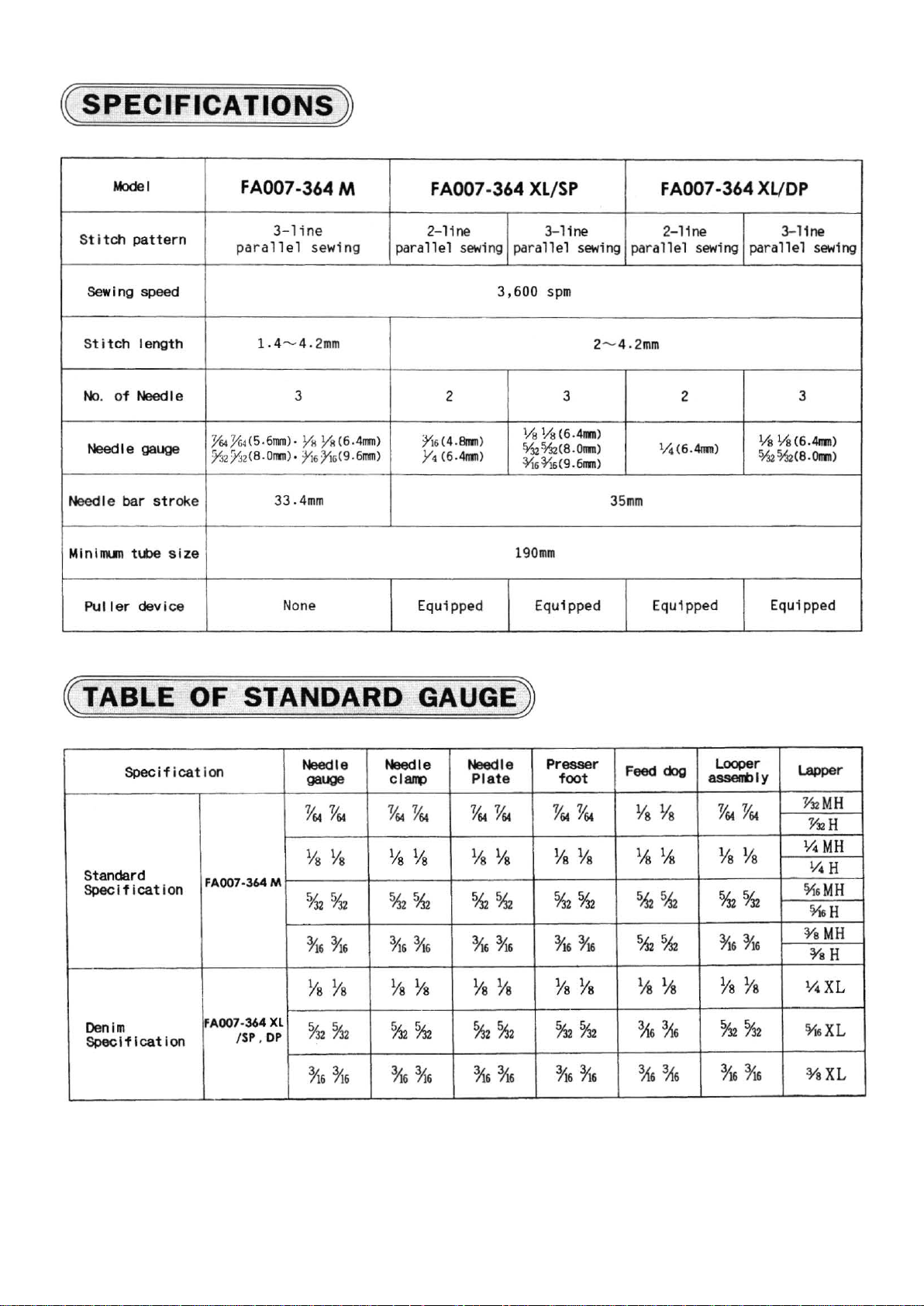
* Machines
prevent sewing irregularity
*M
heavy materials.
* Machines made
*Machines
for a wide
FA007 Double Chain Stitch Feed-off-the-arm Machine is most suitable for sewing tubes of medium and heavy
as
those
made
to
the
achines made
made
ran
to
the puller and the denim specifications employ a movable needle guard which
to
the puller
to
the
ge
of
materials
of
jackets, denim trousers, fatigue clothes and
puller and denim specifications employ a presser foot , a needle p
and
assure
easy
sewing
and
the denim specificatio
puller specificati ons employ a proximity puller system which assures outst anding feeding performance
from medium heavy to heavy.
of
materials
ns
have independent loopers for ease
which
work
may
trou
sers
.
be different
lat
e,
and feed dogs
in
thickness.
of
that
makes
them ideal for sewing
adjustment.
have steps
to
~1~
Page 6
C
SPECIFICATIONS
)
Model
Stitch
St i tch
No.
Need
Min
Puller
pattern
sewing speed 3,600
I ength
of Needle 3
Need
I e gauge
le bar
imum
str
tube
device
oke
size
FA007-364 M
3
-li
ne
paralle
.Y64Yf>~(5.6
:Y.'12/J2(
l sewing
1 . 4
"-'
4.
2mm
nrn)
·
Y11
8.0nrn) • }'i6)'\G(9.6nrn)
33.4mm
YR
None
(6.4nrn)
2-11ne
allel
par
}'i6(4
Y4
Equipped
FA007-
sewing
2
.81!1n)
c6.4nrn>
364
XL/SP
3-
line
paral
lel
sewing
spm
2"-'4. 2mm
3
Vs
Vs
(6.4nrn)
~2%:!(
8.0nm)
~6~
6(9.611111)
190mm
Equ
ippe
d Equipped
FA007
2-11ne 3-11ne
parallel sewing
2
1;4
(6.
35mm
4nrn)
-364
XLIDP
parallel
1
/s
Ys
(6.4nrn)
%%:!
(8.0nn)
Equipped
sewing
3
( TABLE OF STANDARD GAUGEJ
Specificat
Standard
Specification
Denim
Spec
if I cat
ion
ion
FA007-364 M
FA007-364
/S
P ,
DP
Needle Needle
gauge
'V64 'V64
YsYs
%2 %2
%%
%%
XL
%2%2
%%
Clalq)
'V64 'V64
Ys% Ys%
%%
%%
Ys%
%2%
716%
Needle
Plate
'V64
'V64 'V64 'V64
%%
%%
Ys%
%%
%%
Presser
foot
YsYs
%2%2
%%
%%
%z
%2
%%
Feed
YsYs
%%
54 5
~2%
YsYs
%%
%%
dog
tl2
LOOPer
&ssenOiy
'V64 'V64
YsYs
%%
~6%
%%
%z
%2
%%
Lapper
'Y:12
MH
'Y:12
H
114
MH
114
H
¥t&
MH
o/16
H
¥s
MH
¥sH
1
14
XL
o/i&XL
%XL
~2~
Page 7
( INST
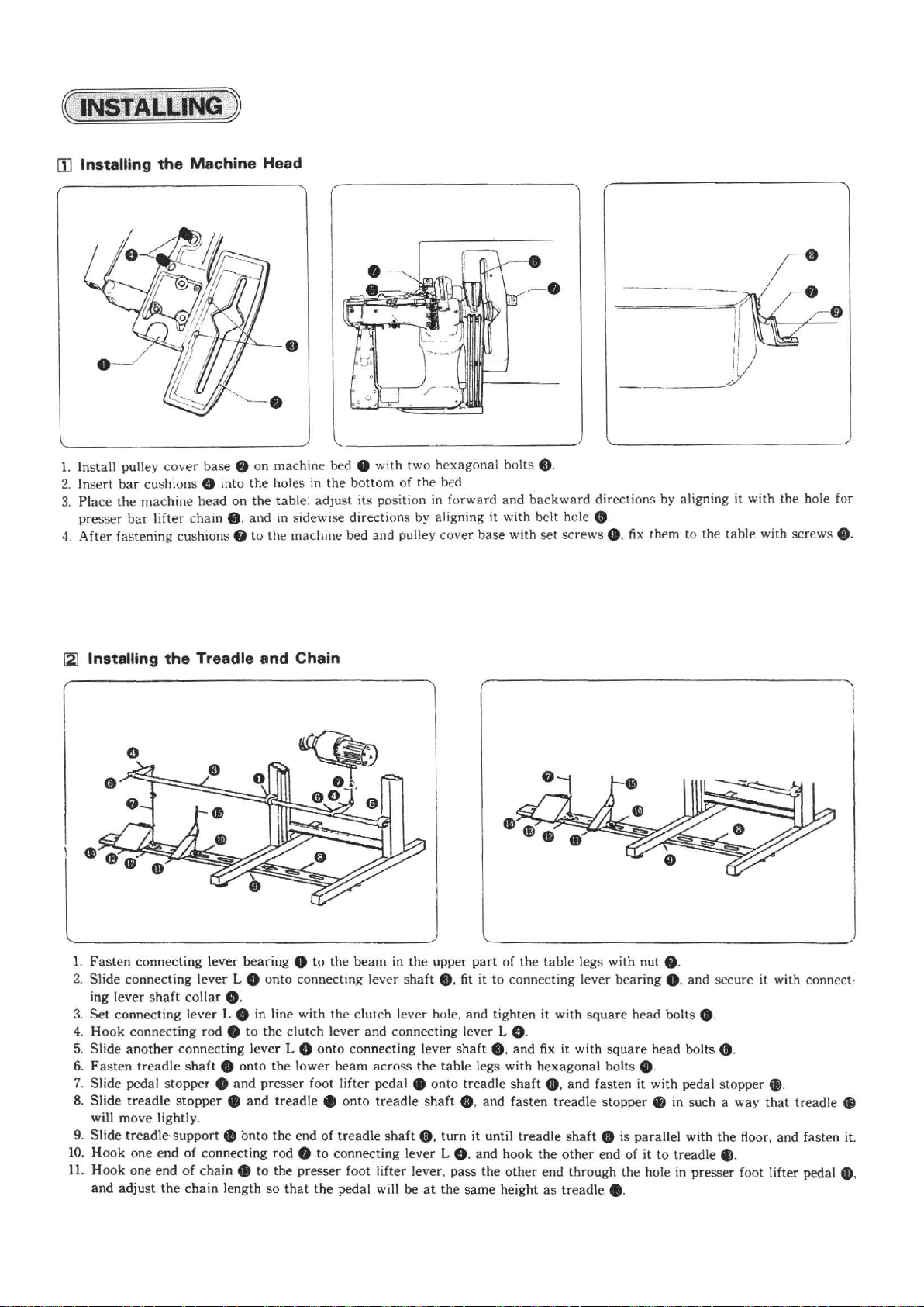
[I]
Insta
1.
Install pulley
2.
Insert
3.
Place
presser
4.
After
ALLING
lling
the Machi
cove
bar
cushions 0 into the holes
the machine head on the table: adjust
bar
lifter chain C). and
fastening cushions 0
)
ne
Head
r base 8 on machine bed 0 with two hexagonal bolts $ .
in
the
in
sidewise directions by aligning it with belt hole e.
to
the machine bed and pulley cov
bottom of the bed.
its
position
in
forward
er
and
base wi
backward
th
set
screws G.
-
-
·
-
-
--
-
~
'
I
__j)
directions by aligning it with the hole for
fix
them to the table with screws
k
.
e.
[2]
Installing
l
~---------------
1.
Fasten
2.
Slide connecting lever L 8 onto connecting lever s
ing lever
3.
Set
connecting lever L 8 in line with the clutch lever hole, and tighten it with
4.
Hook
5.
Slide another connecting lever L 8 onto connecting lever
6.
Fasten
7.
Slide pedal stopper e
8.
Slide
will
9. Slide treadle-
10
. Hook one end of connecting rod e
11.
Hook one end
and adjust
the
connecting l
shaft
connecting
treadle
treadle
move
lightly.
the
Treadle and Chain
----------
ever
bearing e
collar e.
(Od e to
shaft
stopper
support
of
chaine
chain length
the
• onto the l
and
presser foot lifter pedal e onto
e and treadle • onto
e onto the end
to
the presser foot lifter lever , pass the
so
------
clutch lever
ower
that
--------~
to
the beam in the upper
and
beam
of
treadle
to
connecting lever L 8 . and hook the
the pedal will be
across
tread
shaft
part
of the table legs with nut • .
haft
e.
fit
it
to
connecting lever bearing 8 . and secure it with connect-
connecting lever L 0 .
shaft
e. and fix
the
table legs wi
tread
le
shaft
e. and fasten
O. turn
at
the same height
it
th
le
shaft
until treadle
other
square
head bolts e.
it
with
square
hexagonal bo
e. and fasten
treadle
shaft
other
end through the hole
as
tr
eadle e.
lt
s e.
it
with pedal stopper
stopper e in such a way
e is parallel with the floor, and fasten it .
end of
it
head bolts
to treadle e.
(t
.
in
presser foot lifter pedal
e.
that
treadle
411
G),
~3~
Page 8
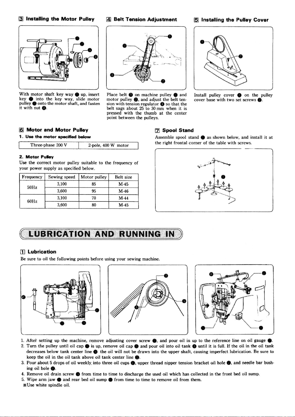
13]
Installing
With
motor shaft
k
ey
8 into the key way, slide
pulley 8 onto
it with
nut 8 .
[6]
Motor
1 . Use
2.
Use
your power supply
the
Three-phase 2
Motor
the correct
the
and
motor
Puley
the
Motor
key
motor
Motor
specified
00
mot
or pulley suitable to the frequency of
as
Pulley
way
8 up, insert
and
motor
fasten
shaft,
Puley
below
V
specified below.
2-pole,
141
Belt Tension Adjustment
•
Place belt 8
mo
tor
sion with tension regulator
belt
sags
pr
essed with
point between the pulleys.
400 W motor
on machine pulley 8 and
pulley 8 . and adjust the belt
about
25
to
the
30
thumb
!5J
lnstaiUng the Pulley Cover
Install pulley cover 8 on
-
cover
base
the
tand 8 as
with two
shown below, and install it
so
the
ten
that
center
8
mm when it is
at
121
Spool Stand
Assemble spool s
the
right frontal corner of the table with screws.
set
scre
the
ws
pulley
8-
at
Frequen
[j]
Be sure to o
cy
50Hz
60Hz
lubrication
•
Sewing speed
3,100
3,60
0
.100
3
3
,600
il
the following points before using
Motor
pulley
85
95
70
80
Belt size
M-
45
M-
46
M-44
M
-45
your
sewing machine.
•
c:::::'
1
I
[
CJ
1.
After setting up
2.
Tum
the pulley until oil
decreases below
keep
th
e oil in
3.
Pour
about
oi
l hole 8 .
ing
4. Rem
ove
oil
5. Wipe
Jl
arm
U
se
white spindle oil.
the
machine, remove adjusting cover screw
tank
the
oil
5 drops
drain
jaw
of
screw e from time
8 and
cap 8 is
center line 8
tank
above
oil
weekly_
rear
into three oil cups
bed
oil sump e from time to time to remove oil from them.
up, remove oil
the
oil will not be drawn into
oil
tank
center
cap
line 8 .
8.
to
time to discharge the
8 .
and
pour oil in up
8 and pour oil into oil
the
upper shaft, causing imperfect lubrication. Be sure to
upper thread nipper
used
oil which
ten
~4~
to
the
ref
eren
ce
line on oil gauge 8 -
tank
8 until it is full. If the oil in the oil
sion
has
bracket
collected
oil hole
in
8.
and needle
the front bed oil sump.
•
bar
tan
bush-
k
Page 9
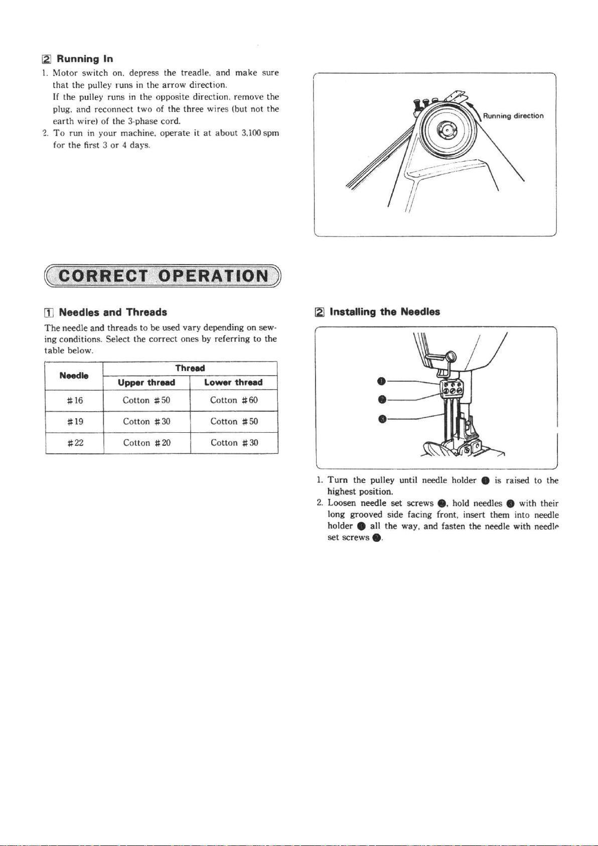
iZJ
Running In
l.
Motor switch o
that the pu
If
the pulley runs
plug. and reconnect two of the three wires (but not the
e
arth
wire) of the 3·phase cord.
'2. To
run in your machine. operate it
for the
(
[]]
The
ing conditions. Sele
table below.
fir
CORRECT
Needles and Threads
needle and
n. depr
ll
ey runs
st 3 or 4
thread
ess the treadle. and
in
the arrow directi on.
in
the opposite direction. remove the
at about 3
day
s.
o.
PERATION
s to be used vary depending on sew·
ct
the
correct
ones by referring to the
make
.100
sure
spm
)
[21
Installing
the
Needles
Needle
~16
~19
~
22
Thread
Upper threed Lower
Cotton
Cotton
Co
tton
~50
~
30
~20
Cotton
Cotton
Cotton
thr
..
~60
~50
~30
d
·--
·-
·--
1.
Tum
the pulley until needle holder 8 is raised to the
highest position.
ed
2. Loosen ne
long grooved side facing
holder
set
screws e.
le set screws e. hold needles e with their
e all the way, and fasten the needle with needll'
--
----
--
(r
ont, insert them into needle
~5~
Page 10
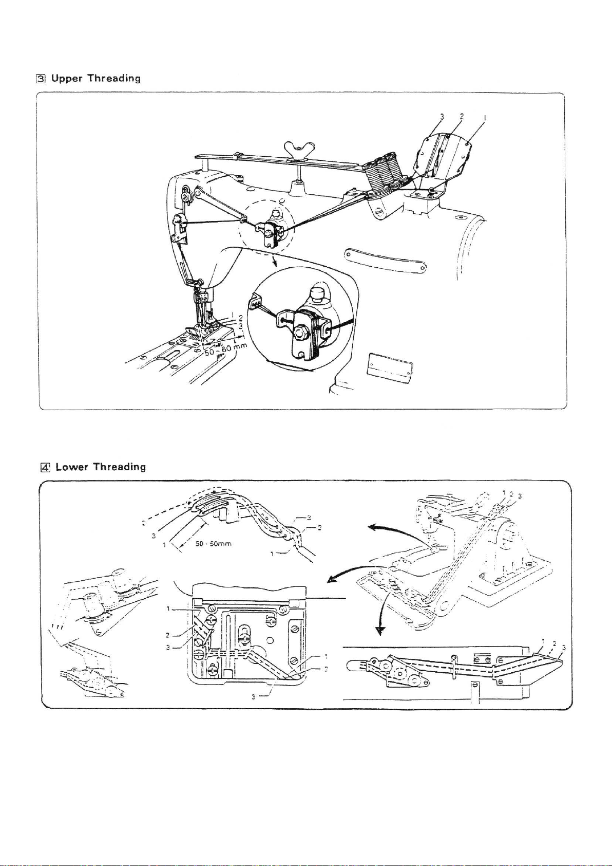
~
Upper
Threading
~
Lower
Threading
~6~
Page 11
[5]
Installing
the
Lapper
/
,r--
Presser f
lapper
oot
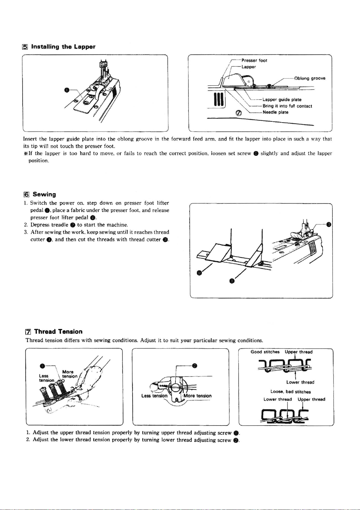
In
sert
the
lapper guide
it
s tip will
ll
lf
position.
16)
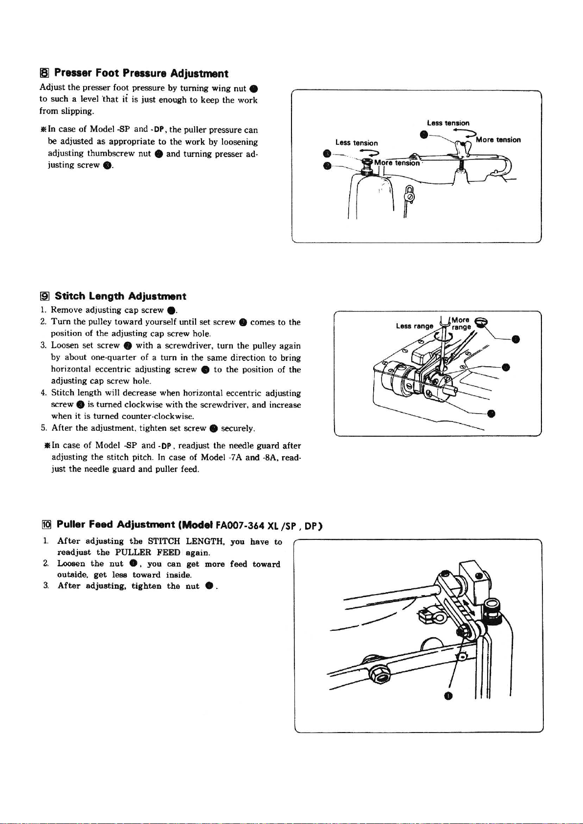
1.
Switch the
pedal8.
presser foot lifter pedal
2.
Depress treadle 8
3.
After sewing the work. keep sewing until
cutter
not
touch the presser foot.
the la pper is too ha rd to move.
Sewing
power
place a fabric under the pre
e.
and
plate
on.
step
8-
to start the
then cut the
into the oblong groove in the forward feed arm. and
down on
machine.
threads
or
fails
to rea
pre
sser fpot lifter
sser
foot. and release
it
reaches
with
thread cutter
ch
the correct position. loosen
thread
e.
~
~
~
"-"-._"'-·-
0
fit
the lapper into place in such a way that
set
screw 8 slightly and adju
:---Lapper
Br
"'-.____
Needle plate
.
C
guide plate
ing
it
into full
o~'""'
••w
••
contact
st
the lapper
•
171
Thread Tension
Thread
tension differs with sewing condition
s.
Adjust
it
to
suit your
particular
sewing condition
· - \
1. Adjust the upper
2. Adjust the lower
thread
tension properly by turning upper thread adjusting
thread
tension properly by turning lower thread adjusting screw e.
~7~
screw
s.
G~
~
8 -
Lower thread
Loose. bad stitch
es
....
~
Page 12
IS]
Presser
Adjust
to such a level 'that
from slipping.
liE
In
case
be
adjusted
adjusting thumbscrew nut
justing screw
19]
Stitch Length Adjustment
1. Remove adjusting
2.
Turn
position of the adjusting
3.
Loosen set screw e with a screwdriver,
by about one·
horizontal eccentric adjusting screw
adjusting
4.
Stitch length will decrease when hori zontal eccentric adjusting
screw
when
5.
After the adjustment, tighten
Foot
Pressure
the
presser foot pressure by turning wing nut e
it
is just enough to keep the work
of
Model -SP and -OP, the puller pressure
as
appropriate
Adjustment
to
the work by loosening
can
e and turning presser ad-
e.
cap
screw e.
the pulley toward yourself until
cap
screw hole.
quarter
cap
screw hole.
of a
turn
set
screw e comes to the
turn
the pulley again
in the same direction
e
to
the position of the
to
e is turned clockwise with the screwdriver, and increase
it
is turned counter-clockwise.
set
screw e securely.
bring
Less tension
•
--::>More
tension
liE
In case of Model -SP
adjusting the stitch pitch. In case of Model ·7 A and ·8A, read·
just
the
needle guard and puller feed.
1!9J
Puller Feed Adjustment (Model FA007-364
1.
After
adjusting
readjust
2. Loosen
outside,
3.
After
the
the
nut
get
adjusting,
the
PULLER
e,
less
toward
tighten
and
-OP,
readjust the needle guard after
STITCH LENGTH, you
FEED
again.
you
can
get
more
inside
.
the
nut
e .
feed
XL
have
toward
to
/SP,
DP)
•
~8~
Page 13
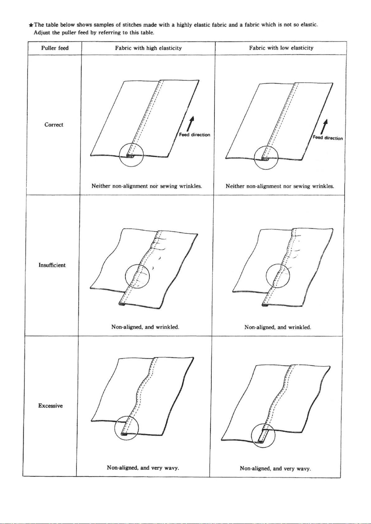
*The
table below shows samples of stitches made with a highly elastic fabric and a fabric which
Adjust the puller
feed by referring to this table.
is
not so elastic .
Puller feed Fabric with high elasticity
Correct
Neither non-alignment nor sewing wrinkles.
Fabric with low elasticity
Neither non-alignment nor sewing wrinkles.
Insufficient
Excessive
Non-aligned, and wrinkled.
Non-aligned, and wrinkled .
Non-aligned, and very wavy.
~9~
Non-aligned, and very wavy.
Page 14
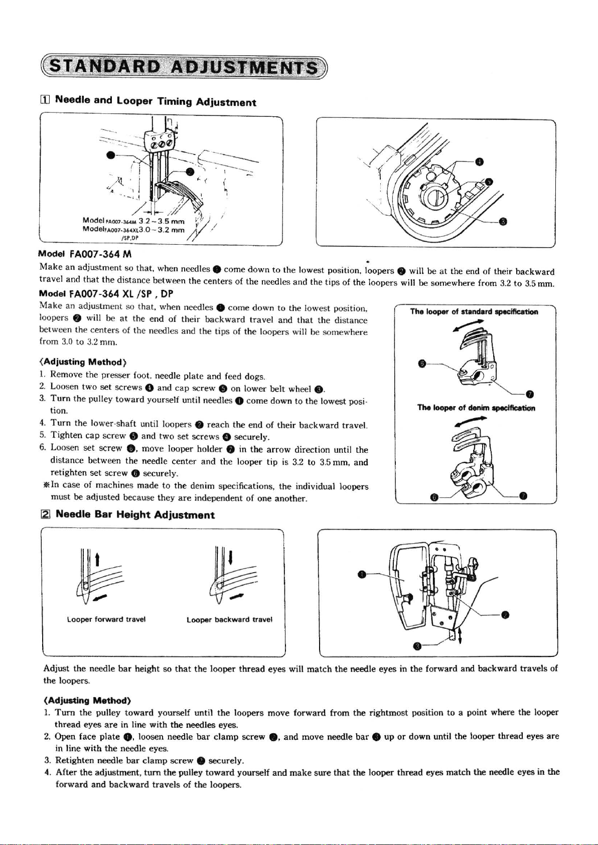
[1] Needle and Looper Timing
Adjustment
Model
FA007-364 M
an
Make
travel and
Model FA007
Mak
loopers
between the cent
from 3.0 to
{Adjusting
1.
2. Loosen two
3.
4.
5.
6. Loosen set screw e. move looper holder 8 in the
IE
[2)
adjustment so that, when needles 8 come down
that
the distance
-364
XL
e an adjustment so that, when needles 8 come down to the lowest position,
8 will
Remove the
Turn
the pulley tow ard yourself until n
tion.
Turn
the lower -s
Tighten
distan
ce
ht
retig
In
case
mu
st
be
Needle Bar
be
at the end
er
s of the needles and the tips of the loopers will be somewhere
3.2
mm.
Method
cap
between the needle center and the looper
en
set
of machines made
adjusted because they
}
pre
sser foot. needle pl
set
screws 8
haft
screw e and two
scre
w e securel
Height
between the centers of the needles and the
/SP ,
OP
of
their b
ackwa
rd
ate
and feed dogs.
and
cap
screw e on lower belt wheel 0 .
eed
les 0 come down to the lowest posi·
until loopers e reach the end of the
set
screws 0 securel
y.
to
the denim specifications, the individual loopers
are
independent of one another.
Adjustment
travel
y.
arrow
tip
to th
e lowest position,
and
that
the distance
ir
backward trave
direction until the
is 3.2 to 3.5 mm, and
tip
s of the loop
l~oper
s
8 wi
ll
ers
will be somewhere from 3.2
l.
be
at
the end of their backward
to
3.5
•
mm.
•
Looper
forward
Adjust the needle
the loopers.
{Adjusting
1.
Tum
thread
2.
Open face
in line
3. Retighten needle
4.
After the adjustment,
forward
Method)
the pull
eyes
with
an
travel
bar
height
ey
toward
are
in line with
plate
e. loosen needle
the
needle eyes.
bar
d backward
Looper bac
so
that the looper
yourself until the loopers move forward from the rightmost position to a point where the looper
the
needles eyes.
bar
clamp
scre
w 8
tum
the pulley toward yourself
trave
ls of the loopers.
kward
thread
clamp
securely.
travel
eyes will
screw
8 . and move needle
and
make sure
mat
ch the needle eyes in the forward and backward travels
bar
that the looper
~10~
•
8 up
or
down until the looper thr
thread eyes match the needle eyes in the
ead
of
eyes are
Page 15
13]
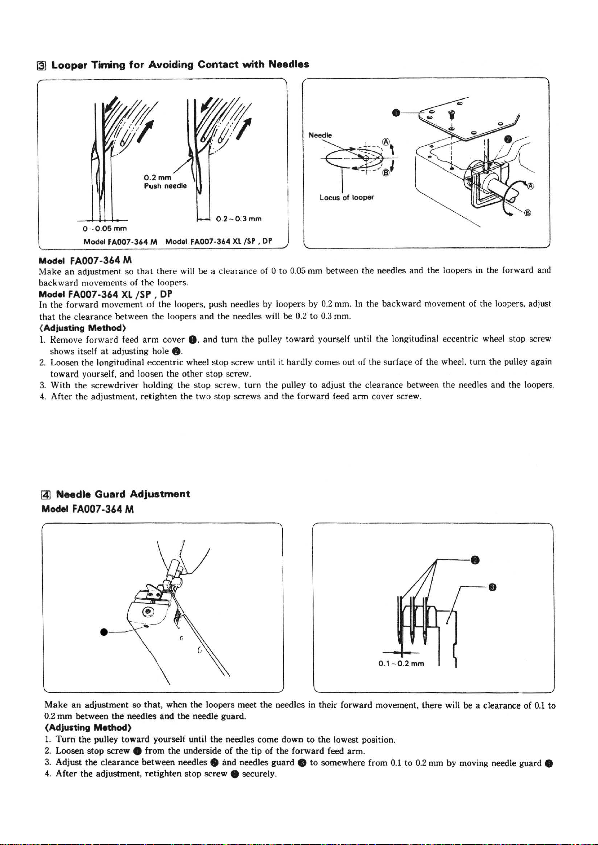
Looper Timing
0 - 0 .
Model FA007-364
05mm
for
Avoiding
0.2mm
Push
needle
M Model FA007-364
Contact
0.2-
Xl/SP,
with
0.3
Needles
•
mm
DP
Model FA007
Make
an
backward movements of the loopers.
Model FA007-364
In
the forward movement of the loopers. push needles by loope
that
the clearance between the loopers and the needles will be 0
(Adjusting Method)
1.
Remove forward feed
shows itself
2.
Loosen the longitudinal eccentric wheel stop screw until it hardly comes out of the surface of the wheel. turn the pulley again
toward yoursel
3.
With the screwdriv
4. After the adjustment, retighten the two stop screws and the forwa rd feed
~
Needle Guard Adjustment
Model FA007-364 M
-364
adjustment so th
M
XL
/SP.
at
adjusting hole • ·
f,
and loosen the other stop screw.
er
at
there will be a clearance of 0 to
DP
arm
cover 8 . and turn the pulley toward yourself until the longitudinal eccentr
holding the stop screw. turn the pulley to adjust the clearance between the needles and the loopers.
0.05
mm between the needles and the loopers
rs
by
0.2
mm.
In
the backward movement of the loopers, adjust
.2
to 0.3
mm.
ar
m cover screw.
in
the forward and
ic
wheel stop screw
•
Make
an adjustme
0.2 mm between the needles
{Adjusting Method)
1.
Tum
the pulley toward yourself until the needles come down to the lowest position.
2.
Loosen
3.
Adjust the clearance between needles e and needles
4.
stop
After the adjustment, retighten stop screw e securel
nt
so
that, when the loopers meet the needles in their forward movement, there w
and
the needle guard.
screw e from the unde
rs
ide of the .tip of the forward feed arm.
guar
d e
to
somewh
y.
~11~
ere
0.
1-0.2
from 0.1 to
•
mm
ill
be a clearance of
0.
2 mm by moving needle guard e
0.1
to
Page 16

Model FA007-364
The
clearance between the needles
lo
opers will be 0.
guard
8 .
XL
/SP,
05
mm, pushing
DP
the
and
the tips of
needles
by
the
needle
(Adjusting Method)
1.
Turn
the
pulley toward yourself until
come down to the lowest position.
2.
Lo
osen stop screw e. and raise
8 so
that
the bottom ends of the needle eyes will be
about 0.5 mm above the bottom of needle
3. T urn the pulley toward yourself again until
of the loopers come to the c
4. Loosen stop screw
left or to the right,
between the needles
be 0.
05
mm, pushing needle points by needle guard
At
this time, please
between the loopers
in the
backward
151
Feed Dog Height Adjustment
Model FA007-364 M
Make
an
adjustment so that. when feed dog e is
pos
ition. the feed
needle
plate
.
Model FA007-364
Make
an ad
justme
be
1.2 mm above
(Adjusting Method)
Adjusting the feed
e.
and
and
make
and
move
ment
dog
will be 0.8 mm above
XL
/SP,
nt
so
that
the
top surface of the needle
dog
height by turning feed
or
enters
move needle
adju
st so
the tips
sure
the needles is 0
of
the
DP
the
highest
the
lower needle
of
the
needles.
guard 8 to
that
the
of
the
loopers will
that
the clearance
.2-
loopers.
the
part
needles
guard
guard
e.
the
tips
the
clearance
8.
0.3 mm
at
top
surface
of
the
feed
plate
.
base
eccentric
the
highest
of
dog
shaft
--
··
-
-·
~1-2mm
0.
05
mm-++---o
the
will
.2 - 0.3
•
mm
••
16)
Puller Height Adjustment (Model FA007-364
Adjust
the
height of puller e so
the top of
{Adjuatlng Method)
Loosen
puller
the
needle plate.
set
screw e. and move puller
e is
0.1
to
0.2
mm
above
that
the
it is
support
top
of
0.1
the
to
0.2
e up
needle
mm
htgh from
or
down until
plate
XL
.
/SP,
DP)
~12~
Page 17

lZJ
Installing
(For
If
stitch irregularities develop in sewing very heavy materi-
al
s, adjust the sub-feed dog
(Adjusting
1. Remove
2.
Placer spac
scre
w e.
!lEThe s
the
the
Method)
set screw
pacer
Spacer
denim
specifications}
to
e and sub-f
er e under sub-feed dog e
is in the
parts
the correct
eed
box.
height by spacer.
dog e.
and
retighten
set
eJ
Upper
Thread
Adjustment
\
I
\
I
\
Model FA007-364 M
Make
an
the lowest position, the
thread hole meets
Model
Please adjust
thread
7-Smm.
FA007-364
take-up and
••· .••
•
Upper thread W
take-up
adjustment so
the
the
distance between the center
Take-up
~
Thread
-..{
-l·ll. guide
Model
FA007-364M
that,
when
top
bottom
XL
/SP ,
the top
Thread
of
the upper thread
of
the
Guide
the
needle
thread guide.
Model
bar
DP
of
the thread guide wi
FA007-
is down
take-up
of
the uppe r
36.X
/SP.OP
at
ll
be
l
19]
Thread
Release
Lever
Adjustment
(Adjusting
1.
Turn
the
down
at
2.
Loosen
th
rea
d guide e
top of
liE
The
higher
greater
Method)
pulley toward yourself until the needle bar is
the
lowe
st
positio
n.
set
screw e. and move upper thread take-up
up
or
down until its bottom meets the
the upper
will be
thread t
th
e upper thread take-up thread guide 8. t
the
ake
-up thread hole.
upper thread loops.
ht
Make
an
the th
re
ad
(Adjusting
1.
Tum
the
2.
Loosen set
tension
liE
Th
e higher
adjustment so
hole in upper
Method}
pulley until
screw
bracket
the
e.
e.
thread
that,
when
thread
tension
the
needle
and
raise
or
release lever,
the nee
dle
bar
is down
bra
cke
t e.
bar
is down
lower thread release lever e until its
the
at the lowest position.
tighter
will
be
at
the
the
lowest position,
stitches.
thread hole meets the thread hole in upp
~13~
the
thread release l
ever
thread hole meets
er
thread
Page 18

I!QI
Thread Release
Make
an
adjustment so
loosen when
presser foot
the
is
Shaft
presser foot is raised , and tighten when the
lowered.
that
the
Adjustment
thread tension discs will
[j] Upper Thread Nipper Adjustment
Adjust the clearance between the upper thread nipper ten-
bracket
sion
0.8 mm and
and tension plates to somewhere between
1.0
mm.
(Adjuating
1.
Loosen stop screw 8 .
2.
Make
so
the presser
the needle
3. After the adjustment, retighten
jgj Lower Thread
Make
move
to 7
(Adjusting
1.
Insert a screwdriver into the adjusting hole in the bed,
and loosen two stop screws
2. Raise lower
take-up
3. After
Method)
an
adjustment by turning thread release s
that
the
thread tension discs will begin
foot
is raised 4 mm above
plate
.
stop
Take-up
an adjustment so that, when the loopers begin to
backward
mm
, lower thread take-up e will rise about 5
above lower
Method)
thread
Timing Adjustment
take-up
to
loosen when
the
top surface of
screw 8 securely.
bracket
• ·
e.
thread
take-up 0 5 to 7 mm above thread
bracket
the
• ·
adjustment, retighten
two
stop screw e.
haft
(Adjusting
1.
Loosen
•
sion
and tension plates
*Stitch
ance between upper thread nipper tension bracket
the
Method)
stop
bracket
tightness
arm.
screw
8.
and move upper thread nipper ten-
• in
or
out until the clearance between it
e is somewhere from 0.8 to
can
be improved by
narr
owing the clear-
7mm
1.0
mm.
8 and
~
Puller Device Timing Adjustment (Model FA007-364
1.
With
3mm
2.
The timing
needle
6mm.
3.
After
• &
wrench
of
is
away
and
stoping
adjusting the
•.
the
from
to
loosen
feed
the
at
lOmm.
timing.
will
needle
the
screw
be
stsrting
plate
retighten
8 & e
when
about 5 or
the
screw
the
XL
/SP
, DP)
~14~
•
Page 19

(TROUBLESHOOTING)
Trouble
Thread breaks.
Needles break.
I
I
Needles installed
improperly_
Upper thread tension too
great.
Lower thread tension too
Thread
Needle eyes too sma
threads.
Loopers
'---------
!lieedles damaged.
'------------
Needles hit loopers.
Needles in
improperly.
Needl
Needle
threads.
Cause
relea
damaged
es
hit
eyes
sta
se
lever
out
ll
for
.
---
--
--------'
lled
needles guard.
too small for
I
of
t---
-'
I----
L
Inspection
Direction of long groove.
Upper thread tension.
Lower thread tension.
Threa
d release lever
and
Needle size
---------
----
Direction of long groove.
rciearance
and needles guard.
Needle size and thread
thread
------11
--
-------1JRep
between
n~edles
I
I
L
Refer to-
'--
ne __
J
Ref~r_t_o_t_h_e
.__"
smooth
~d__e~per
~n
Adjust looper timing to
avoid contact with needles.
Ad' t. ell d
Remedy
;;;-
s-t-ru_c_t-
e_d_l_e_i_ns_t_a~l_ir_tR
_
N_e_ed_l_e_s_an_d_T_h_r~ds"'
loopers with
or_?~.!!
lace needles with
__
e_s_.
________________ ~ __
--
---------··----
JUS
nee
------------
I Refe; to the -sec
"l'<eedles
and
io_n_s_f_o;-l·
:
_ _
____ , __
-se-.c-ti_o_n_
o_
n_ --r---
1
_
___j
_::~_
-r~
-
·
_
____1:-::::
~ood
I
--
-EJ
- -
e~
guar . !
--t-:Threads"
~--;!
i-on
__
o_n
__
--,
-
--=-~
:J
__
j
-
l
J
_ J
j
5
_ j
1
11
_j
-----'
1
___
~
Stitches
Upper
skip.
threads loose.
Needles installed
improperly.
Looper
points
are
'------
Needle
wrong.
Clearance between needles
and loopers too
Lower
timing wrong.
Upper
small.
Lower thread tension too
great.
Upper
guide
Upper
not tighten upper threads.
-
and
thread
thread
thread
out
of position.
thread
dull. r---
--
-----'
looper timing
great.
take-up
tension too
take-up
thread
nipper does
Direction of long groove.
--
------
Needle and looper timing.
r:C~
I-ea-r-an
_c_e 7be_t_w-ee_n_n_ee_d_l
and looper
Lower
timing.
Upper
Lower thread tension.
t-----------------------
Tension
s.
thread
thread
plate
------t
~s
take
-up
tension.
~Ie
arance
.
Refer to instructions for
needle installing.
Replace loopers with good I
Adjust needle and looper
timing.
Adjust clearance
needles and loopers. __
~djust
lower thread
·
ttmtng. ,
~
~
th~ea-
I I Adjust
---
upJX'r
d
guide position. .
u)!lper
~
~___.1
__ ._l_l
betw~-~
____
take·u~
~--
thread take-up
thr
ead
n~pper
c
10
10
-1-l
j_
-
~
14
7
ll
13
~
14 !
.
_
__
1
j
_j
1
l
j
~15~
Page 20

Tr
ouble
I
I
Cause
I I
Inspection
I I
Remedy
I Pag
el
Feed dog too low.
Presser foot pressure too
small.
not
Machine does
work.
Non-lllignment lind
wrink
...
(Model · FA007·364M )
Non-alignment lind
wrinkles
(Modei·FADD7·364XL/~f.Df]
feed
Feed dog worn out.
Presser foot floats and does
not fully press work.
Feed dog and presser foot
work on one side only.
Sub feed dog height
incorrect.
Presser foot pressure
incorrect.
Feed dog height incorrect.
Pu
ll
er
Puller feed incorrect.
Presser foot pressure
incorrect.
timing wrong.
Feed dog height. Adjust feed dog height.
Presser foot pressure.
Adjust presser foot
pressure.
I Have serviceman check it.
I Have serviceman check it.
Have serviceman check
them.
Sub feed dog height. Adjust sub feed
Presser foot pressure.
Feed dog height. Ajust feed dog height.
Puller timing. Adjust puller device timing.,
Puller feed.
Presser foot pressure.
Adjust presser foot
pressure.
Adjust puller feed.
Adjust presser foot
pressure.
dog
height.
L/1
L/1
14
Feed dog height incorrect.
Feed
dog
height. Adjust feed dog height.
~16~
Page 21

CONTENTS 目錄
CO-MACHINE BODY
............................................................................1
機體下拉布輪
C1-UPPER SHAFT MACHANISM
......................................................3
上軸結構
C2-NEEDLE BAR MECHANISM-FEED MECHANISM
針柱與送布傳動結構
C3-PULLY MECHANISM
......................................................................7
皮帶傳動結構
C4- PRESSER BAR MECHANISM
....................................................9
壓腳柱結構
C5-LOOPER MECHANISM
................................................................11
彎針傳動結構
C6-UPPER THREADING MECHANISM
.........................................13
上導線張力結構
................5
C7-LOWER THREADING MECHANISM
........................................15
下導線張力結構
C8-LOWER SHAFT MECHANISM-GAUGE PARTS
....................17
下軸結構與針位組
C9-GAUGE PARTS(SP) SP
..............................................................19
針位組
C10-GAUGE PARTS (DP) DP
..........................................................21
針位組
C11-PULLER DEVICE MECHANISM DP、SP
............................23
上拉布輪結構
C12-ACCESSORIES
...........................................................................25
配件
~17~
Page 22

4
1
C2
CO~1~
Page 23

MACHINE BODY
REF. NO.部件編號
C0-01
C0-C2
C0-04
C0-05
C0-05-1
C0-06
C0-07
C0-08
C0-09
C0-11
C0-11-1
C0-12-1
C0-12A
C0-B17-1
C0-A17-3
C0-17-3
C0-18
C0-X28-1
C0-X31
C0-X67
C0-X67-2
C0-X77
MACHINE HEAD 機體(上)
MACHINE REST BOARD 機體(下)
OIL PLUG 油塞
LOWER WHEEL 拉布輪
LOWER WHEEL 拉布輪
LOWER WHEEL CONNECTION 拉布輪軸
ONE WAY TRIANGULAR AXLE 單向三向軸片
ONE WAY STILL SPRING 單向彈簧
ONE WAY STILL BALL 單向滾珠
ONE WAY PUSHING PLATE 單向推輪
PIN 銷
FEED DOG PUSHING PLATE LINK 推輪連桿
SCREW 合葉螺釘
PULLER COVER 導蓋(右)
PULLER TOP COVER 護輪蓋
PACKING 導蓋
PLASTIC COVER 橡膠塞
SCREW 11/64×40 螺釘
SCREW 9/64×40 L8 螺釘
SCREW 3/32×56 螺釘
SCREW 3/32×56 L6 螺釘
SCREW 11/64×40 L9 螺釘
NAME OF PARTS 說明
Amt req需求量
1
1
1
1
1
1
2
6
6
1
1
1
1
1
1
1
2
2
3
3
3
2
~2~
Page 24

Y2
4
4-1
PL,PL-M,SP
X9
X38-1
X38-1
SM
9-1
6-1(PL,SP,PL-M)
PL,PL-M,SP
7-1
6(SM)
31
16
C1~3~
Page 25

UPPER SHAFT MACHANISM
REF. NO.部件編號
C1-01
C1-02
C1-03
C1-04
C1-04-1
C1-Y2
C1-06
C1-06-1
C1-07
C1-08
C1-09
C1-7-1
C1-9-1
C1-10
C1-11
C1-12
C1-13
C1-14
C1-15
C1-16
C1-17
C1-18
C1-18-1
C1-18-2
C1-18-3
C1-19
C1-21
C1-22
C1-22A
C1-23
C1-24
C1-25
C1-26
C1-27
C1-29
C1-30
C1-31
C1-102
C1-102-1
C1-X3
C1-X4
C1-X5
C1-x6
C1-X7
C1-X9
C1-X38-1
PULL BAR ENDING SCREW 合葉螺釘
VERTICAL PULL BAR 傳動連桿
PULL BAR BEARING 滾柱軸承
VERTICAL PULL BAR FIXING SCREW 合葉螺釘
WASER 墊圈
PULL BAR SCREW NUT 止動螺母
UPPER SHAFT 上主軸
UPPER SHAFT 上主軸
BALL BEARING 6202 軸承
BEARING SUPPORT 軸承圈
OIL STOPPER 油封
FIXING BUSHUNG 上軸套(前)
CHOCK RING 定位圈
BEARING CASE ASSEMBLY 軸套筒
BEARING 6302 軸承
OIL TANK 儲油器
OILGAUGE WINDOW 油鏡
PACKING 油封墊圈
OIL GAUGE FLANGE 儲油器蓋
OIL TANK PACKING 止油銅墊圈
PACKING 橡膠墊圈
UPPER WHEEL ECCENTRIC WHEEL 偏心凸輪
ECCENTRIC WHEEL WASHER 凸輪蓋
BEARING 滾柱軸承
SCREW 9/64×40 螺釘
UPPER WHEEL MOVING PULL BAR 凸輪傳動連桿
PULL BAR SCREW NUT 合葉螺釘
FIXING PULL BAR SCREW WASHER 止滑墊圈
WASHER 墊圈(厚PL,PL-M,SP)(薄PL,PL-M)
PULL BARSCREW NUT 螺母
THICKNESS ADJUSTING PULL BAR 擺動傳桿
PULL BAR FIXING PULL BAR 螺釘
UPPER WHEEL CONNECTION 傳動軸
MOVABLE LEFT-RIGHT CHOCK RING 定位圈
CONNECTION COPPER TUBE 銅套筒
VERTICAL PULL BAR 雙頭合葉螺釘
WASHER 墊圈
BEARING FIXING SCREW 外牙螺母
BEARING FIXING BUSHING 緊壓套筒
SCREW 15/64×28 螺釘
SCREW 15/64×28 螺釘
SCREW 9/64×40 螺釘
CAP SCREW 覆蓋螺釘
SCREW 1/4×28 螺釘
SCREW 15/64×28 螺釘
SCREW 11/64×40 螺釘
NAME OF PARTS 說明
Amt req需求量
1
1
2
1
1
1
1
1
1
1
1
1
1
1
1
1
1
1
1
1
1
1
1
1
2
1
1
2
2
2
2
2
1
1
2
1
1
1
1
1
1
4
1
2
2
2
~4~
Page 26

10(PL-M,SM)
10-1(PL,SP)
12-1(PL-M,SM)
12(PL,SP)
9(PL-M,SM)
9-1(PL,SP)
11(PL-M,SM)
11-1(PL,SP)
(PL,SP,#22)
(PL-M,SM,#18)
X9
3(PL-M,SM)
3-1(PL,SP)
(PL,SP) 66
(PL-M,SM) 7
×
×
X7
C2~5~
Page 27

NEEDLE BAR MECHANISM-FEED MECHANISM
REF. NO.部件編號
C2-01
C2-02
C2-03
C2-03-1
C2-04
C2-05
C2-C6
C2-07
C2-08
C2-09
C2-09-1
C2-10
C2-10-1
C2-11
C2-11-1
C2-12
C2-12-1
C2-14
C2-15
C2-16
C2-17
C2-18
C2-C19
C2-20
C2-C21-1
C2-22
C2-23
C2-24
C2-C25
C2-26
C2-X7
C2-X8
C2-X9
C2-X10
C2-X14
C2-X31-1
C2-X49
C2-X66
NEEDLE BAR CRANK 固定軸
NEEDLE BAR CRANK BOD 提升連桿
NEEDLE BAR BRACKET 針柱夾
NEEDLE BAR BRACKET 針柱夾
WICK 油蕊
OIL LEAK PROOF CAP 防油蓋
WICK 油蕊
NEEDLE BAR GUIDE SLIDE BLOCK 四方滑塊
NEEDLE BAR GUIDE 導軌
NEEDLE BAR 針柱
NEEDLE BAR 針柱
NEEDLE BAR BUSHING (UPPER) 針柱套筒(上)
NEEDLE BAR BUSHING (UPPER) 針柱套筒(上)
NEEDLE BAR BUSHING (LOWER)針柱套筒(下)
NEEDLE BAR BUSHING (LOWER)針柱套筒(下)
THREAD TAKE-UP CRANK 平衡凸塊
THREAD TAKE-UP CRANK 平衡凸塊
OIL CAP 橡膠塞
NEEDLE 針(PL,SP#22)(PL-M,SM#18)
FEED DOG ECCENTRIC AXLE 調節凸輪
WASHER 墊圈
ECCENTRIC WHEEL SLEEVE 銅滑塊
ECCENTRIC WHEEL WITH SCREW 上下凸輪
ECCENTRIC WHEEL SLEEVE 銅滑塊
FEED BAR SLIDE BLOCK ASSEMBLY 送布傳動曲柄
PACKING 油封墊圈
FEED LIFTING FORK 叉動柄
FEED BAR SLIDE BLOCK ASSEMBLY 四方滑塊
FEED BAR ECCENTRIC SHAFT 偏心軸
FEED DOG ECCENTRIC SET 固定座
SCREW1/4×40 螺釘
SCREW11/64×40 L12 螺釘
SCREW 15/64×28 螺釘
SCREW 15/64×28 螺釘
FEED ECCENTRIC ADJUSTING SCREW 倒位螺釘
SCREW 9/64×40 螺釘
SCREW 9/64×40 L5 螺釘
THREAD TAKE-UP CRANK 平衡凸塊
NAME OF PARTS 說明
Amt req需求量
1
1
1
1
1
1
1
1
1
1
1
1
1
1
1
1
1
1
3
1
1
1
1
1
1
1
1
1
1
1
5
4
5
2
1
1
1
1
~6~
Page 28

X7
C3~7~
X7
Page 29

PULLY MECHANISM
REF. NO.部件編號
C3-01
C3-02
C3-03
C3-04
C3-05
C3-06
C3-07
C3-08
C3-09
C3-10
C3-20
C3-X01
C3-X07
X3-X09
C3-X18
C3-X22
C3-X79
PULLEY 皮帶輪
TIMING BELT WHEEL ASSEMBLY (SUPPER) 同步皮帶輪(上)
TIMING BELT WHEEL ASSEMBLY (LOWER) 同步皮帶輪(下)
TIMING BELT 同步時規皮帶
BELT COVER 皮帶座
BELT COVER PLATE 皮帶座蓋板
PACKING 防油墊片
PULLEY COVER BASE 配重固定塊
PULLEY COVER 皮帶輪護蓋
WASHER 墊圈
SPRING COIL O型彈圈
SCREW1/4×28 螺釘
SCREW1/4×28 螺釘
SCREW1/4×28 螺釘
SCREW 15/64×28 螺釘
SCREW 7/16×14 螺釘
SCREW 3/16×32 L8 螺釘
NAME OF PARTS 說明
Amt req需求量
1
1
1
1
1
1
1
1
1
2
3
2
5
2
2
2
2
~8~
Page 30

(SP,SM)
D2-27
SP
X95
1A
5-1
C4~9~
1B(PL)
1(PL-M,SM )
5(PL,PL-M,SM)
Page 31

PRESSER BAR MECHANISM
REF. NO.部件編號
C4-01
C4-1A
C4-1B
C4-02
C4-03
C4-04
C4-05
C4-5-1
C4-06
C4-07
C4-08
C4-09
C4-10
C4-11
C4-12
C4-13
C4-14
C4-15
C4-16
C4-17
C4-B18
C4-19
C4-20
C4-24
C4-X8
C4-X9
C4-X25
C4-X26
C4-X27
C4-X31
C4-X44
C4-X60
C4-X95
C4-Y02
C4-D2-27
PRESSR BAR 壓腳柱
PRESSR BAR 壓腳柱
PRESSR BAR 壓腳柱
FACE PLATE UPPER HINGE ASSEMBLY 蝶型後鈕
STEEL BALL 鋼珠
PRESSER BAR BUSHING (UPPER) 壓腳柱軸套(上)
PRESSER BAR BUSHING (LOWER) 壓腳柱軸套(下)
PRESSER BAR BUSHING (LOWER) 壓腳柱軸套(下)
FACE PLATE (LOWER) 前蓋板(下)
PACKING 防油墊片
PRESSER BAR CLAMP ASSEMBLY 壓腳柱夾
PRESSER BAR CLAMP SPRING 壓力板
PRESSER BAR CLAMP SPRING PIN 定位銷
PRESSER BAR CLAMP SPRING ASSEMBLY 上壓力彈片
GUIDE WASHER 定向墊片
WING NUT 蝶型螺母
PRESSER BAR LIFTER 壓腳提放勾
KNEE LIFTER LEVER 壓腳提放柄
KNEE LIFTER SPRING 壓腳提放彈簧
PRESSER FOOT LIFTER CHAIN ASSEMBLY 傳動鏈條
FACE PLATE (UPPER) 前上蓋
STOPPER SPRING PLATE (L) 彈片勾(外)
STOPPER SPRING PLATE (S) 彈片勾(內)
OIP CAP 油塞
SCREW11/64×40 螺釘
SCREW 15/64×28 螺釘
PRESSER ADJUSTING SCREW 全牙螺釘
STUD SCREW 15/64×28 螺釘
STUD SCREW 5/16×28 螺釘
SCREW 9/64×40 L10 螺釘
SCREW 9/64×40 螺釘
SCREW 9/64×40 螺釘
SCREW 9/64×40 螺釘
SCREW 3/16×32 螺母
RUBBER PLUR 橡膠塞
NAME OF PARTS 說明
Amt req需求量
1
1
1
1
1
1
1
1
1
1
1
1
1
1
1
1
1
1
1
1
1
1
1
1
1
2
1
1
1
3
4
1
1
1
1
~10~
Page 32

2
C29
X35
C5~11~
21
Page 33

LOOPER MECHANISM
REF. NO.部件編號
C5-02
C5-C3
C5-C4
C5-C5
C5-06
C5-C7
C5-C8
C5-09
C5-10
C5-C11
C5-12
C5-C13
C5-A14
C5-C15
C5-16
C5-17
C5-C18
C5-C19
C5-20
C5-21
C5-22
C5-23
C5-25
C5-26
C5-27
C5-C28
C5-C29
C5-C30
C5-C31
C5-32
C5-33
C5-702
C5-X9
C5-X28
C5-X28-1
C5-X31
C5-X32
C5-X34
C5-X35
C5-X36-1
C5-X37
C5-X38-1
C5-X42
C5-X50
C5-X56
C5-Y01
ECCENTRIC WHEEL SLEEVE 銅滑塊
LOOPER FEEDING FORK 滑動叉
LOOPER FEEDING SHAFT 滑動叉(軸)
LOPPER FEEDING SHAFT BRACKET 滑動叉基座
PIN 叉銷
LOOPER FRONT-REAR TRANSMISSION 前後驅動連桿
SLIDE BROCK SHAFT 固定軸牙
LOOPER LEVER SHAFT ?節固定軸
PACKING 墊圈
CONNECTING ROD GUIDE PLATE 上下驅動連桿
WASHER 墊圈
LOOPER SHAFT CLAMP 傳動軸夾
LOOPER SHAFT 傳動軸
LOOPER SHAFT BUSHING (F) 傳動軸套筒(後)
LOOPER SHAFT BUSHING (B) 傳動軸套筒(前)
SET COLLAR 定位夾
FORWARD ARM CONER ASSY 平面蓋板
PACKING 防油墊片
OIL GAUGE 探油棒
PACKING 橡膠墊圈
CAP PLATE 下軸蓋
PACKING 防油墊片
"8"TYPE TRANSMISSION DEVICE 8字銅連桿
ECCENTRIC WITH SCREW 小凸輪
EYEPIECE H型連桿
STEEL BALL 萬向滾珠
LOOPER SLIDE BASE 連桿固定片
WASHER 波浪彈片
LOOPER FEEDING FORK 叉動柄
---
--SQUARE BALL 四方滑塊
SCREW 15/64×28 螺釘
SCREW 11/64×40 螺釘
SCREW 11/64×40 螺釘
SCREW 11/64×40 螺釘
SCREW 11/64×40 螺釘
SCREW 3/16×32 螺釘
SCREW 3/32×56 螺釘
SCREW M3.5 L=10 螺釘
SCREW 11/64×40 螺釘
SCREW 11/64×40 螺釘
SCREW 1/2×28 螺釘
SCREW 9/64×40 L=5 螺釘
SCREW 15/64×28 螺釘
NUT 15/64×28 螺釘
NAME OF PARTS 說明
Amt req需求量
1
1
1
1
1
1
1
1
1
1
1
1
1
1
1
1
1
1
1
3
1
1
1
1
1
1
1
1
1
1
1
1
2
1
1
16
2
1
2
4
1
2
3
4
2
1
~12~
Page 34

i
X65
1
7-1
n
X44
PL ' SP • PL
X51
T~
X
-M -
26
SM -826
~~1-1
30
~
e
~lU1
r
XB
~
I i
ij
w
~-..j
X34
-1
~-~
~
34(PL-M,SM)
34-1(PL,SP)
C6~13~
Page 35

UPPER THREADING MECHANISM
REF. NO.部件編號
C6-01
C6-03
C6-06
C6-07
C6-7-1
C6-08
C6-09
C6-10
C6-11
C6-12
C6-13
C6-14
C6-15
C6-16
C6-17
C6-18
C6-23
C6-24
C6-25
C6-26
C6-27
C6-28
C6-29
C6-30
C6-31
C6-32
C6-33
C6-34
C6-34-1
C6-35
C6-36
C6-37
C6-38
C6-39
C6-A40
C6-41
C6-43
C6-44
C6-X8
C6-X9
C6-X31-1
C6-X34-1
C6-X44
C6-X47
C6-X48
C6-X49
C6-X50
C6-X51
C6-X53
C6-X54
C6-X56
C6-X58
C6-X59
C6-X65
C6-B26
C6-C22
C6-Y04
UPPER THREAD GUIDE RETAINER 上導線座
BRACKET 過線片
THREAD HANGER 導線圈
LINE GUIDE DEVICE 倒位基座
PIN 銷
TENSION SPRING WASHER 彈簧墊圈
TENSION SPRING WASHER 彈簧墊圈
NUT 螺母
TENSION DISC 沙拉片
TENSION DISE PRESSER 張力墊圈
UPPER THREAD TENSION SPRONG 張力彈簧
UPPER THREAD RELEASE PIN 銷
THREAD RELEASER SHAFT 轉軸
--
-UPPER THREAD TENSION SUTD SCREW 過線固定片
LOWER THREAD TENSION PLATE 張力夾線片
PIN 銷
TENSION RELEASE CRANK 連桿
TENSION RELEASE CONNECTING BAR 上線鬆放提柄
THREAD RELEASER LEVER 撥線片
THREAD RELEASER LEVER SAFT 撥線軸
TENSION RELEASE CONNECTING ROD 連桿
TENSION RELEASE LINK 小連柄
TENSION RELEASE SUTD 壓腳柱夾
THREAD GUIDE 導線勾
WASHER 墊圈
UPPER THREAD TAKE-UP LEEVER ASSEMLY 天秤
UPPER THREAD TAKE-UP LEEVER ASSEMLY 天秤
THREAD CHECKER 天秤夾線片
SPRING 彈簧
LOWER THREAD GUIDE 導線勾(D)
WASHER 墊圈
UPPER THREAD TENSION REGULATOR ASSEMBLY ?通導線片
UPPER THREAD TENSION SUTD ASSEMBLY 張力調節軸
UPPER THREAD TENSION SPRING 彈簧
WASHER 墊圈
UPPER THREAD FASTENING CAM WITH SCREW 上線張力凸輪
SCREW 9/64×40 螺釘
SCREW 15/64×28 螺釘
SCREW 9/64×40 螺釘
SCREW 11/64×40 螺釘
SCREW 9/64×40 L=5 螺釘
SCREW 11/64×40 螺釘
SCREW 9/64×40 螺釘
SCREW 9/64×40 L=6 螺釘
SCREW 9/64×40 螺釘
SCREW 11/64×40 螺釘
SCREW 9/64×40 螺釘
SCREW 3/32×56 螺釘
SCREW 15/64×28 螺釘
UPPER THREAD TENSION STUD SCREW 叉口合葉螺釘
SCREW 11/64×40 螺釘
SCREW 3/32×56 L=4 螺釘
TENSION RELEASE CONNECTING BAR 上線鬆放提柄
THREAD TAKE-UP COVER 天秤護蓋
NUT 11/64×40 螺釘
NAME OF PARTS 說明
Amt req需求量
1
1
1
1
1
3
3
3
6
3
3
1
1
3
4
1
1
1
1
1
1
1
1
1
1
1
1
1
1
1
1
1
1
1
1
1
2
1
1
2
1
1
2
1
1
1
1
1
2
3
1
2
2
1
1
~14~
Page 36

X31-1
X92
X44
X9
X31-1
C7~15~
X31-1
Page 37

LOWER THREADING MECHANISM
REF. NO.部件編號
C7-01
C7-02N
C7-03
C7-03N
C7-06
C7-12
C7-12-1
C7-17
C7-A10
C7-A11
E7-A12
C7-A14
C7-A14-1
C7-A17
C7-A18
C7-A50
C7-A51
C7-A55
C7-C20-B
C7-C21-B
C7-C22-B
C7-C23-B
C7-C25-B
C7-27
C7-28
C7-29
C7-30
C7-31
C7-32
C7-33
C7-34
C7-35
C7-36
C7-37
C7-39
C7-40
C7-41
C7-44
C7-45
C7-47-1
C7-48
C7-49
C7-A50-2
C7-A50-3
C7-A50-4
C7-A51-4
C7-C68
C7-X9
C7-X31電
C7-X31-1
C7-X31-2
C7-X44
C7-X45
C7-X50
C7-X60
C7-X64
C7-X65
C7-X66
C7-X67-1
C7-X92
C7-X95
C7-Y05
LOERT THREAD GUIDE RETAINER 導線架(上)
THREE PIPE-LINE THREAD TUBE 三線過線管
BRACKET 過線片
THREAD TUBE CLAMP 導線圈
LOWER THREAD GUIDE SUPPORTER 支架輔助
LOWER THREAD GUIDE HINGE ASSEMBLY 活動鈕(上)
LOWER THREAD GUIDE HINGE ASSEMBLY 活動鈕插銷
LOWER THREAD COVER 橡膠墊
LOWER THREAD COVER 下前蓋
PLATE SPRING 彈簧勾
FIXING PLATE 活動鈕(下)
LOWER THREAD TENSION BRACKET 三通過線片
THREAD GUIDE 穩線片
LOWER THREAD GUIDE RETAINER ?通過線片
PLATE SPRING 彈片勾
LOOPER SIDE COVER (R) ASSY 彎針護蓋
LOOPER SIDE COVER (L) ASSY 彎針護蓋
LOWER THREAD GUIDE 過線片
THREAD TENSION ROD 沙拉螺柱
LOWER TEREAD TENSION BRACKET 沙拉托架
LOWER TEREAD TENSION NUT 沙拉螺母
LOWER TEREAD TENSION PLATE 沙拉片
LOWER TEREAD TENSION SPRING 沙拉彈簧
THREAD TAKE-UP LEVER COVER 護線蓋
SPRING 彈簧勾
LOWER THREAD TAKE-UP LEVER FRAME 過線輔助架
LOWER THREAD TAKE-UP LEVER COVER SHAFT 銷
LOWER THREAD TAKE-UP LEVER BASE 過線支架
GUIDE PLATE 過線輔助架
WASHER 墊圈
LOERT THREAD GUIDE PLATE 固定片
SCREW 彈簧
WASHER 墊圈
LOWER THREAD GUIDE(LEFT) 彈片扣
LOWER THREAD GUIDE(LEFTRIGHT) 導線勾
LOWER THREAD GUIDE(LEFT) 導線勾
LOWER THREAD GUIDE PLATE 固定片
LOWER THREAD TAKE-UP DISC ASSEMBLY 配線凸輪
LOWER THREAD FEED TUBE 過線管
LOOPER THREAD GUIDE BRACKET 針受座
THREAD CUTTER GUIDE PLATE 切線刀
THREAD CUTTER 切線刀
STOPPER SPRING PLATE 彈片勾
PIN 銷
FACE PLATE UPPER HINGE ASSEMBLY(R) 蝴蝶後扭(右)
FACE PLATE UPPER HINGE ASSEMBLY(L) 蝴蝶後扭(左)
PIN 銷
SCREW 15/64×28 螺釘
SCREW 11/64×40 螺釘
SCREW 11/64×40 螺釘
SCREW 9/64×40 L10 螺釘
SCREW 9/64×40 L5 螺釘
SCREW 9/64 螺釘
SCREW 9/64 螺釘
SCREW 9/64×40 L4 螺釘
SCREW 3/32×56 螺釘
SCREW 3/32×56 L4 螺釘
SCREW 1/4×40 螺釘
SCREW 3/32×56 螺釘
SCREW 9/64×40 螺釘
SCREW 9/64×40 螺釘
NUT 9/64×40 螺母
NAME OF PARTS 說明
Amt req需求量
1
1
1
6
1
2
2
2
1
2
2
1
1
1
2
1
1
1
3
3
3
6
3
1
1
1
1
1
1
1
1
1
1
1
2
1
1
1
1
1
1
1
2
4
1
1
1
1
3
12
2
7
2
2
1
3
2
2
6
1
1
2
~16~
Page 38

PL-M,SM
L1
L2
X3
18
14H
X44
X50
A20
A19
A21
C10-11
C8~17~
Page 39

LOWER SHAFT MECHANISM-GAUGE PARTS
REF. NO.部件編號
C8-C1
C8-02
C8-03
C8-04
C8-05
C8-06
C8-07
C8-08
C8-09
C8-10
C8-C10-11
C8-11
C8-14H
C8-15
C8-18
C8-A19
C8-A20
C8-A21
C8-102
C8-L1
C8-L2
C8-X3
C8-X31
C8-X32
C8-X44
C8-X50
C8-X74-1
C8-X75
C8-X77
C8-X79
C8-X81
C8-X82
LOVER SHAFT 下主軸
BEARING 6200 Z 軸承
BEARING 6201 Z 軸承
BALL BEARING BUSHING 內套筒
BEARING CASE ASSEMBLY 軸套筒(下)
BEARING FIXING BUSHING 緊壓套筒
NEEDLE CLAMP WITH SCREW 針夾
NEEDLE PLATE 針板
PRESSER FOOT ASSEMBLY 壓腳組
FEED DOG 送布齒
NEEDLE GUARD 針受
BEARING 6302 軸承
LAPPER ASSEMBLY 導布架喇叭
SPRING 彈簧
LOOPER LONG 彎針(長)
LOOPER HOLDER (SHORT) 彎針台(短)
LOOPER HOLDER (MIDDLE) 彎針台(中)
LOOPER HOLDER (LONG) 彎針台(長)
BEARING FIXING SCREW 外牙螺母
LOOPER SHORT 彎針(短)
LOOPER MEDIUM 彎針(中)
SCREW 5/16×28 螺釘
SCREW 9/64×40 螺釘
SCREW 11/64×40 螺釘
SCREW 9/64×40 螺釘
SCREW 9/64×40 L10 螺釘
SCREW1/4×28 螺釘
SCREW 11/64×40 螺釘
SCREW 11/64×40 螺釘
SCREW 3/16×32 螺釘
SCREW 9/64×40 螺釘
SCREW 9/64×40 螺釘
NAME OF PARTS 說明
Amt req需求量
1
1
1
1
1
1
1
1
1
1
1
1
1
1
1
1
1
1
1
1
1
1
1
3
3
3
1
1
3
1
1
2
~18~
Page 40

SP
D8-13K
A17
A16
14XL
A18
C9~19~
Page 41

GAUGE PARTS(SP) SP
REF. NO.部件編號
C9-01
C9-02
C9-03
C9-05
C9-06
C9-07
C9-09
C9-11
C9-14XL
C9-15
C9-A16
C9-A17
C9-A18
C9-A19
C9-A20
C9-A21
C9-X9
C9-X44
C9-X50
C9-X77
C9-X79
C9-X82
C9-X83
C9-X86
C9-X91
C9-X93
C9-Y05
C9-D8-13K
NEEDLE CLAMP ASSEMBLY 針夾
NEEDLE PLATE 針板
PRESSER FOOT ASSEMBLY 壓腳頭
PRESSER FOOT (F) SPRING 彈簧
PRESSER FOOT ASSEMBLY 壓腳底
SUB FEED DOG 導布齒
FEED DOG 送布齒
NEEDLE GUARD 針受
LAPPER ASSEMBLY 導布架喇叭
NEEDLE GUARD BRACKET 針受連結
LOOPER (SHORT) 彎針(短)
LOOPER (MIDDLE) 彎針(中)
LOOPER (LONG) 彎針(長)
LOOPER HOLDER (SHORT) 彎針台(短)
LOOPER HOLDER (MIDDLE) 彎針台(中)
LOOPER HOLDER (LONG) 彎針台(長)
SCREW 15/64×28 螺釘
SCREW 9/64×40 螺釘
SCREW 9/64×40 螺釘
SCREW 11/64×40 螺釘
SCREW 3/16×32 螺釘
SCREW 9/64×40 螺釘
STUD SCREW 螺釘銷
SCREW 3/32×56 合葉螺釘
SCREW 5/64×60 螺釘
SCREW1/8×44 螺釘
NUT 9/64×40 螺釘
SCREW 9/64×40 螺釘
NAME OF PARTS 說明
Amt req需求量
1
1
1
1
1
1
1
1
1
1
1
1
1
1
1
1
1
1
4
3
1
1
2
1
2
3
1
1
~20~
Page 42

PL
X65
A17
A16
14XL
A18
C10~21~
Page 43

GAUGE PARTS (DP) DP
REF. NO.部件編號
C10-01
C10-02
C10-03
C10-04
C10-05
C10-06
C10-07
C10-08H
C10-09
C10-10
C10-11
C10-14XL
C10-A16
C10-A17
C10-A18
C10-A19
C10-A20
C10-A21
C10-X31
C10-X32
C10-X44
C10-X50
C10-X65
C10-X77
C10-X79
C10-X82
C10-X83
C10-X86
C10-X87
C10-X88
C10-X89
C10-X91
C10-X93
NEEDLE CLAMP ASSEMBLY 針夾
NEEDLE PLATE 針板
SPRING M 彈簧
SPRING F 彈簧
SPRING BL 彈簧
PRESSER FOOT ASSEMBLY 前壓腳底
SUB FEED DOG 導布齒
NUT 1/8×44 螺母
FEED DOG 送布齒
SPRING BS 彈簧
NEEDLE GUARD 針受
LAPPER ASSEMBLY 導布架喇叭
LOOPER (SHORT) 彎針(短)
LOOPER (MIDDLE) 彎針(中)
LOOPER (LONG) 彎針(長)
LOOPER HOLDER (SHORT) 彎針台(短)
LOOPER HOLDER (MIDDLE) 彎針台(中)
LOOPER HOLDER (LONG) 彎針台(長)
SCREW 9/64×40 螺釘
SCREW 11/64×40 螺釘
SCREW 9/64×40 螺釘
SCREW 9/64×40 螺釘
SCREW 3/32×56 螺釘
SCREW 11/64×40 螺釘
SCREW 3/16×32 螺釘
SCREW 9/64×40 螺釘
STUD SCREW 螺釘銷
SCREW 3/32×56 螺釘
SCREW 1/8×44 L5 螺釘
SCREW 1/8×44 螺釘
SCREW 3/32×56 螺釘
SCREW 5/64×56 螺釘
SCREW 1/8×44 螺釘
NAME OF PARTS 說明
Amt req需求量
1
1
1
1
1
1
1
1
1
1
1
1
1
1
1
1
1
1
1
1
3
3
1
3
1
1
3
1
1
1
1
2
3
~22~
Page 44

PL,PL-M
9A
D1-9
X9
10
X19
SP
11
14
X67-1
13
15
12
X67-2
9
X47
X31
X82
X67-1
21A
22A
20A
X82
19A
C11~23~
X67
17A
Page 45

PULLER DEVICE MECHANISM DP、SP
REF. NO.部件編號
C11-01
C11-02
C11-03
C11-05
C11-06
C11-07
C11-08
C11-09
C11-10
C11-11
C11-12
C11-13
C11-14
C11-15
C11-17
C11-A18-1
C11-D1-9
C11-X09
C11-X19
C11-X31
C11-X47
C11-X47
C11-X67
C11-X67-1
C11-X67-2
C11-X82
C11-01A
C11-02A
C11-03A
C11-04A
C11-05A
C11-06A
C11-08A
C11-09A
C11-10A
C11-12A
C11-14A
C11-16A
C11-17A
C11-18A
C11-19A
C11-20A
C11-21A
C11-22A
PRESSURE ADJUSTING SCREW 外牙螺母
UPPER WHEEL PRESSER BAR 立軸
SPRING 張力彈簧
WHEEL DIRECTION FIXING DEVICE 拉布輪壓力提柄
FRESSER ROD BUSHING 軸套
UPPER WHEEL SEAT 拉布輪架
UPPER WHEEL CONNECTON 固定軸
ONE WAY PULL HOLDER 拉柄
PACKING 防油墊片
LOWER WHEEL 拉布輪
ONE WAY TRIANGULAR WHEEL 單向三角軸片
UPPER WHEEL 拉布輪
ONE WAY STILL BALL 單向滾珠
ONE WAY STILL SPRING 單向彈簧
CHOCK RING E型扣環
FACE PLATE (UPPER) DP上前蓋座
RUBBER PLUG 橡膠塞
SCREW 15/64×28 螺釘
SCREW 螺釘
SCREW 9/64×40 螺釘
PRESSER FOOT LIFTER 螺釘
SCREW 螺釘
SCREW 3/32×56 螺釘
SCREW 3/32×56 螺釘
SCREW 3/32×56 螺釘
SCREW 9/64×40 螺釘
PRESSURE ADJUSTING SCREEW 外牙螺母
NUT 螺母
PRESSER FOOT LIFTER 手提柄
STUD SCREW 固定銷
SPRING 張力彈簧
PRESSER BAR GUIDE ASSEMBLY 拉布輪壓力提柄
ROLLER PRESSER BAR LIFTER 舌片
SCREW PRESSER ROD BUSHING 螺釘
PRESSER ROD BUSHING 軸套
UPPER WHEEL PRESSER BAR 立軸
PULLER SUPPORTER ASSEMBLY 拉布輪架
ONE WAY PULL HOLDER 拉柄
UPPER WHEEL CONNECTON 固定軸
FACE PLATE 拉布輪基座
ONE WAY TRIANGULAR WHEEL 單向三角軸片
UPPER WHEEL 拉布輪
ONE WAY STILL BALL 單向滾珠
ONE WAY STILL SPRING 單向彈簧
NAME OF PARTS 說明
Amt req需求量
1
1
1
1
1
1
1
1
1
1
2
1
6
6
1
1
4
1
2
1
1
1
3
6
3
3
2
1
1
1
1
1
1
5
1
1
1
1
1
1
2
1
6
6
~24~
Page 46

16
2-1
C12~25~
Page 47

ACCESSORIES
REF. NO.部件編號
C12-01
C12-02
C12-2-1
C12-03
C12-04
C12-05
C12-06
C12-07
C12-08
C12-09
C12-10
C12-11
C12-12
C12-13
C12-14
C12-16
C12-X1
C12-X2
THREAD STAND 六葉線架
CUSHION ASSEMBLY 固定座
WASHER 墊圈
BASE CUSHION 橡膠墊塊
HEAD COVER 防塵套
OIL TANK 大油壺
OILER ASSEMBLY 小油瓶
NEEDLE 針
TWEEZERS 線夾
SPANNER 固定板手(#7)
SPANNER 固定板手(#8)
SCREW DRIVER 大起子
SCREW DRIVER 小起子
SCREW DRIVER 中起子
THREADLE 腳踏板
SPANNER 固定板手(#10)
SCREW1/4×28 螺釘
SCREW 6.2×26 木螺釘
NAME OF PARTS 說明
Amt req需求量
1
2
2
2
1
1
1
5
1
1
1
1
1
1
2
1
2
2
~26~
Page 48

Sir:tUaA
TABLE
CUT-OUT
750
725
Series
Item Code
FA007 FA007-T1
I
!
\
:
~
---------
0
0
co
..-i
om
com
(\J(\J
r
Subclass I Remark
• FOR FA007 Series
L()
co
(Y)
012
L()
(Y)
L()
Mounting
Fully-submerged
Date
2014 I 7 I 18
f+1>
~
~
-jmg
~
~
~!CF
~
~
;;;o""'
~
lt
"@
n
0
4~
\:':
'-
I--<
/'--j
Am3
""'3
~
- =
~
~
~ln~
§j
D~
~
~
~
fQ
I+
[\)
~
-¥=
680
210 4-R10
.~b------+-~~v---t--t-
g -
-------
-----
--
520
026
~
..
lrl
..
08.5
A-A
:§iJtm
017
-f=-r--
85
o--~~----~--------------------------~r---~-~---0
L()
co
0
 Loading...