

Page 1
FA007
1im~a~W*f!:FII
·
INSTRUCTION AND PARTS LIST
·
Sir:.UaFr
·
CE
ml
GE
~
®
ai~fti1S3f5i~~fla]
KAULIN
MFG~CO
..
LTD
.
Page 2

Page 3

Page 4
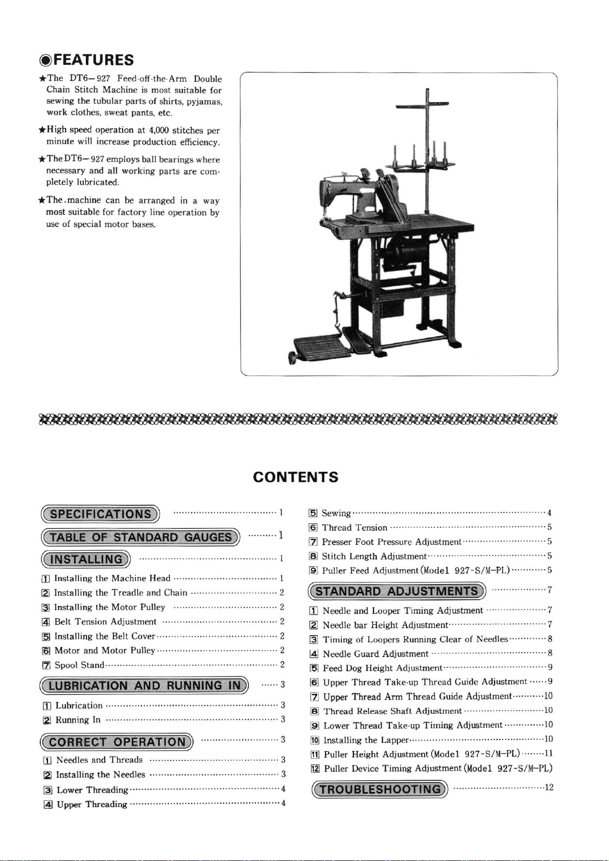
(f) FEATURES
*The
DT6-927 Feed
S
Chain
sewing
work
tit
the tu
clothes,
ch Machine is
bular par
swe
at
-off-th
e-Arm
most
ts of shirts, pyjamas,
pant
s, etc.
Double
suitable for
*High
*TheDT6-
*The.machine
speed
operat
minute
necessary
pletely lubricated.
most
u
se
will in cr
927 employs ball
and
suitable
of
special
ion
at
4,000 stitches
ease
production efficiency.
all
working parts
can
be
arranged
for
factory
motor
line
bases.
bearings
are
in a
operation
per
where
com-
way
by
~
SPECIFICATIONS
~
TAB
LE
OF
STANDARD
~JN
STALLING
[I]
Ins
talling
the Machine Head
121
Installing the
(3]
In
sta
lling
~
Belt
Tension
[5)
Installing the
161
Motor
111
Spool
~
LUBRICAT
[I]
Lubrication
121
Running In ....
~
CORRECT
[I]
Needl
es
(2]
Installing
@]
Lower
~
Upper
Treadl
the
Motor
Adjustme
Belt
and
Motor
Sta
nd
.... ·
ION
···
.....
OPERATION
and
Threads .....
the
Needles
Threading··
Threading
....
.............
~
~
................................................
e and Chain ....
Pulley
nt
.. ......
Cover .... ·
Pulley
.......................... · ........
.
AND. RUNNING
· ..
......... · .................
·········
· · · · · .. · · · · · · · · · · · .. · · · .. · · · · · · · · .. · .. · · · · · · · · · .. · · · 4
..............
..........................................
............
..............
...... ·
........
················
CONTENTS
............
....................................
....................................
........................
GAUGES» ..........
...............
...................
· .. · .. · .. ·
....................
~
...........................
..........................
··
...
· · ·
·························
....
....
........
........
··
....
..........
IN
~
· .. · ·
.................
....
......
...................
.... · 2
· .... 2
......
.. . 2
· 3
·· · 3
1
1
l
l
2
2
2
3
3
3
3
4
~
Sewing
[§]
Thr
1Zl
Presser
~
Stit
~
Puller
~
STANDARD
[I] Needle
~
@]
~
[5]
[§]
11J
1§1
~
[I2J
[1]
~
~
TROUBLESHOO
........
ead
Tension
Foot
ch Le
ngth
Feed
and Looper
Need le
Timing
Needle
Feed
Upper
Thread
Low
In
bar
Height Adjustment
of Loopers Running
Guard
Dog
Height
Thread
Upper
Thread
Release
er
Thread
sta
lling the Lapper· .. ·
Puller
Height Adjustme
Puller Devi
ce
...
.................
...............
Pressure Adjustment
Adjustment .........................................
Adju
stment(Mo
ADJUSTMENTS»
Timing
Adjustment
Adj
Take
Arm
Sha
Take-up
Timing
.....
...
del
Adju
............
ustment"
-up
Thread
Thr
ead
ft
Adjustment
Timing
...
. ·
........................
nt (Model 92
Adjustment (
TI
NG
................
........
.............. · ........
927-S/M-PL
stment
....
............
Clear
...............
Guide Adjustment
Guide Adjustment
Adjustment .....
»
......
.......
................
) ........ .... 5
....
.........
...
........
.............
of
Needles
.......
...........
....
...............
... ....
.....................
............. ·lO
7-
S/M
-PL)
Mod
el 927 -S/ M- PL)
...............
......
.... . 4
............
· .. · .. 5
......
.........
.....
.........
..........
......
...........
.........
........
...........
5
5
7
· 7
7
.... 8
8
9
9
10
10
1Q
11
12
Page 5
(SPECIFICATIONS)
Model
Use
Stitch
pattern
Max. se
Stitch lengt
Needle
Needle
Needle
Min. arm
Puller
wing
speed
h
gauge
bar stroke
size
device
(TABLE
Ga
uge
set
Needle holder Needle
Y.MH
!J<s
MH
Y.
MH
OF
Ya
!J<s
Y.
Thin
materials
Twin
-needle,
3,600
spm
1.2
-2.5
mm
)(5
inch
(4.8
mm)
27
mm
_j___
Equipped _
STANDARD
plate
Ya
!J<s
Y.
H
_
GAUGES)
Presser
Ya Ya
!J<s
Y.H
foot
FA007
I
twin-thread
I
Ys
inch
Medium-thick
double
(3.2
mm)
TVxl
I
178mm
Feed
dog
Looper
!J<s !J<s
Y.
H
chain
4,000 spm
1
.2-3.2
I%
inch
materials
stitch, parallel sewing
mm
(4
mm) I
~
inch
27mm
None
assemblY
.
Looper
oruide .....,
Ya
Y.
H
(4.8
thread
Ya
Ya
Y.H
I Thick materials
mrn)
I U
inch
30
I
(6.4
mm
Lapper
Ya
MH
~~
MH
Y.MH
mrn)
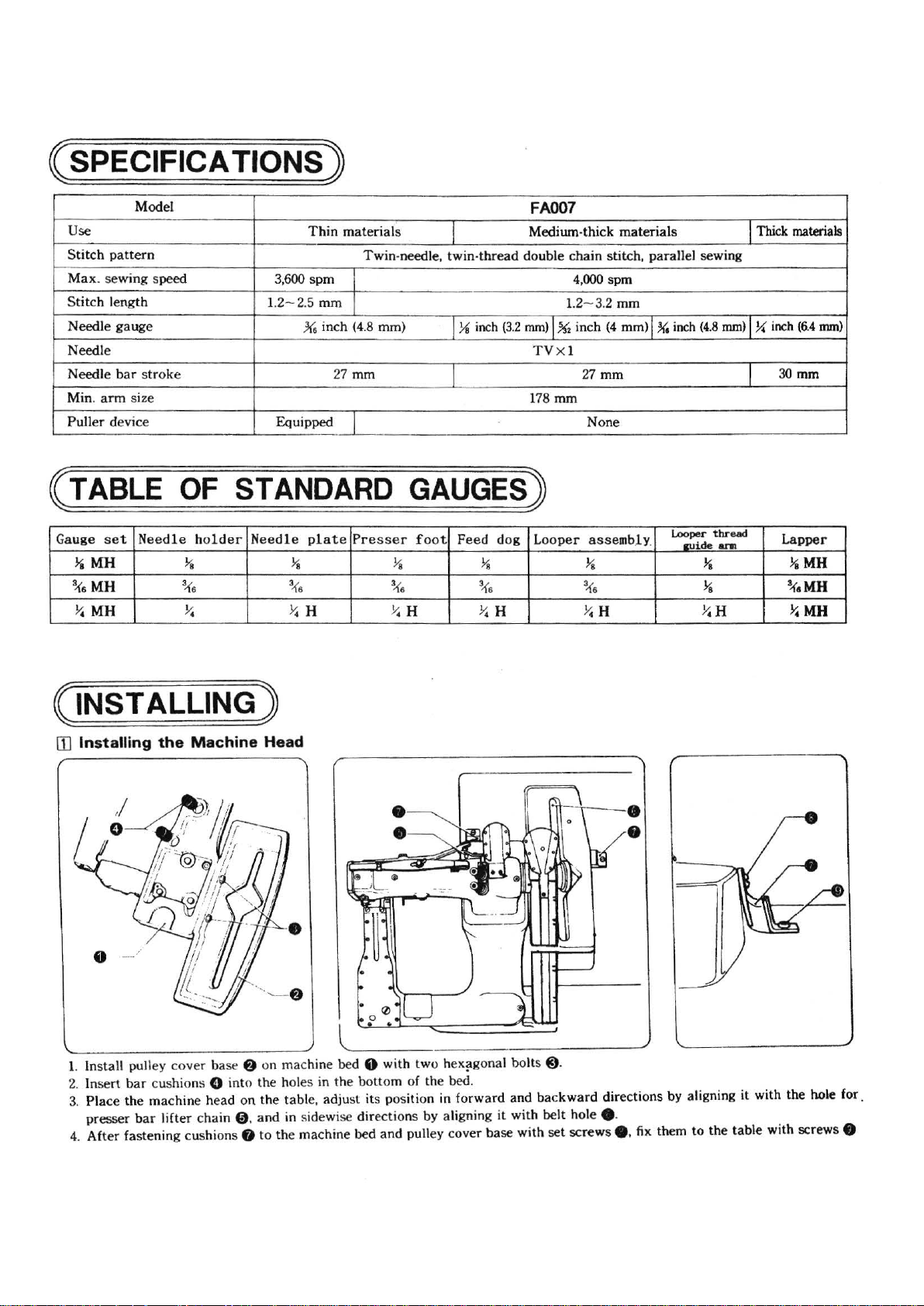
(INSTALLING)
[]]
Installing
1.
Install pulley
2. Insert
3.
Place
presser
4. After
the
Machine
cover base 8 on
bar
cushions 0 into the
the mac
fastening
bar
lifter chain
hine head on
cushions 8 to
0 .
Head
the
and
machine
holes in the
table, adjust
in sidewise
the machine
bed
0 wi
th
two hex
bottom
directions
bed
of the bed .
its position in
and
pulley
by
aligning it
cover base
l"g
onal
forward
bolt
s
@).
and bac
with belt
with
set
kward
hole e.
screws
directions
e. fix them
by ali
gning it with the hole for.
to
the
table
with screws 0
~1~
Page 6
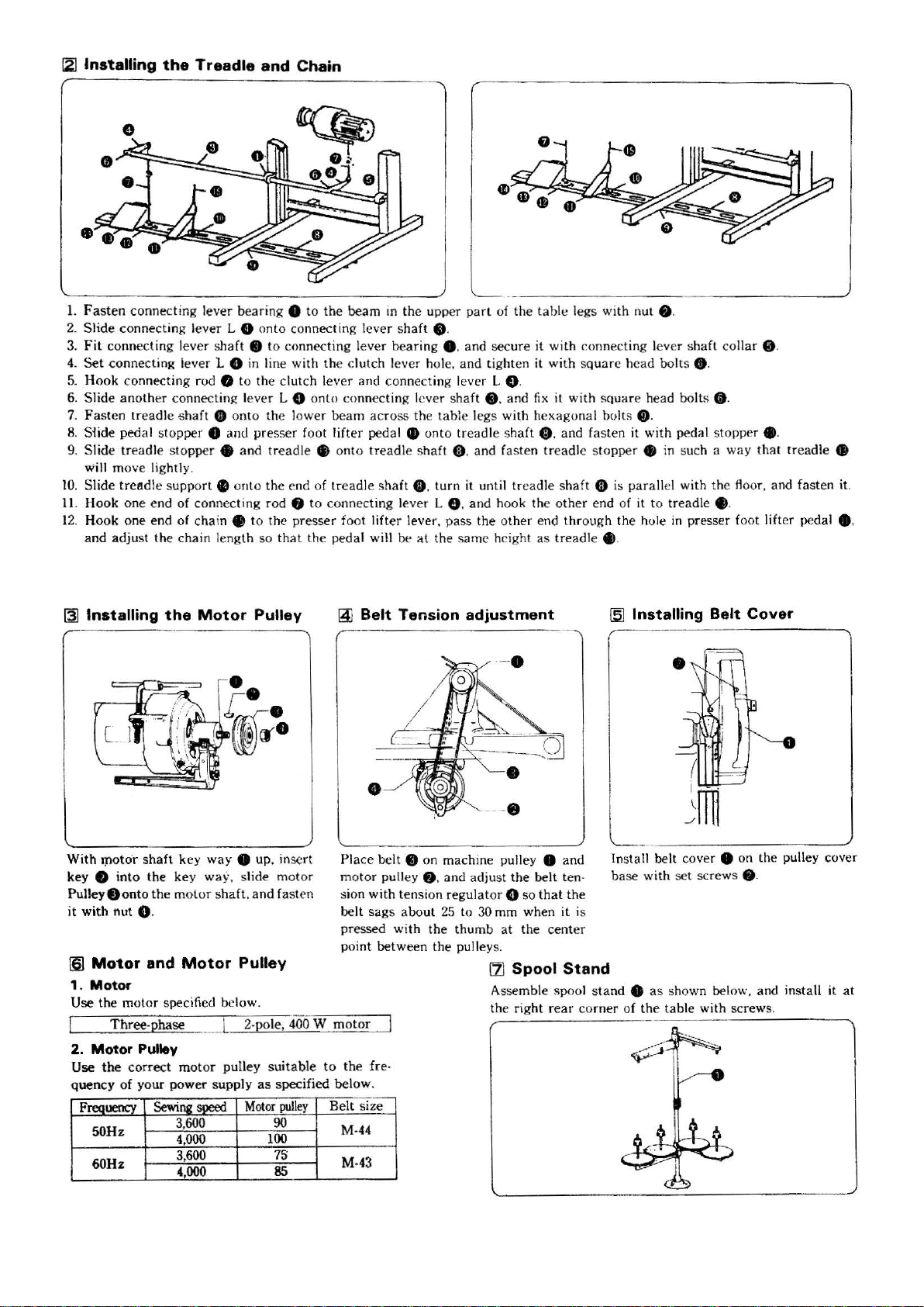
121
Installing
1. Fasten
2. Slide
3.
Fit connecting lever s
4.
Set conne
5.
Ho
ok conn
6. Slide
7.
Fast
en
8.
Siide pedal stopper 8 and
9. Slide
will move lightly .
10
. Slide t
11.
Ho
ok
1
2.
H
ook
and
adj
the
Treadle
connecting
connecting le
cting lev
ect
ing rod 0 to
anoth
er connec ting le
treadl
e shaft 0
treadl
e stopp
re
edle
support e
one
end of connecting rod 8
one
end
of
chain e to
ust
the
chai
and
Chain
lever
bearing 8 to
ver
L 0 onto
haft
er
L 0 in
onto
er e and treadle •
on
n len
gth
connecting lever shaft
• to connecting lever bearing
li
ne
with
the
clut
ch lev
ver
L 0 on
the low
presser
to the end
the
so
that the
pre
foo t lifter peda
the
beam
the
clutch lever
er
and connecting l
to connecting l
er
beam across
onto
tread
of
tre
adle shaft 0 . turn
to
connec
ting
sser foot
lift
pedal will be
in the u
pper
8 .
e.
and
hole.
and
ever
eve
r s
haft
the
tab
le l
l e
onto treadl
le
shaft
G. and f
it
lever L 8 .
er
lever. pass the oth
at
the same height
L _ _
part
of
the
tab
le legs
with
nut • ·
sec
ure
it with connecti
tighten it with s
L
G.
e. and
egs
unt
and
fix
with hexagonal bol
e shaft 0 .
asten tread
il treadle shaft G is parallel with the floor.
hook the
er
end
as
quare head
it with square
and
le s
other
through
tread
ng
lever sh
bol
ts
head bol
ts
Cl)
.
fasten it wi
topper
end of it
le e.
th
pedal stopp
e in such a
to
tre
adle • .
the hole in presser foot lift
af
t coll ar e.
• .
ts
• .
way
er
e.
that
and
treadle
fasten it.
er
peda
•
l • .
[3]
Installing
With
!pOto·r
key e
Pulley
f)
it
with
161
Motor
1.
Motor
Use
the m
2.
Motor
Use the
q
uen
cy
F
50Hz
60Hz
the
shaft
ke
into
the key way, slide
onto
the
motor shaft.
nut 8 .
and
Motor
otor
spec
Thr
ee-phase
Pulley
correct
of
your
Sewing
mot
power
3,
4,000
3,
4,000
Motor
y way 8 up. in
Pulley
and
Pulley
ifi
ed
below.
2-
pole, 400 W motor:]
or pull
ey suit
sup
ply
as
speed
600
600
Motor
~
sert
motor
fasten
able
specified below.
pull
90
100
75
85
to the fre·
ey
Belt
Pl
motor pull
sion with
belt
pr
poi
M-44
M-4
Belt
•
ace
belt e
sags about
essed
with
nt
between
size
3
Tension
on
machin
ey
• . and adju
tension
regulat
25
the thu
the
adjustment
/
·-·
·
-·
e pulley 8 and
st
the belt ten·
or 8 so that
to 30 mm wh
mb
at the
pulleys.
LlJ
Spool
Assemble spool
the right
the
en
it is
center
Stand
rear corn
15.1
Installing Belt
In
sta
ll
base
with
stand 8 as
er of the
Cover
belt c
over
8 on the pulley cover
set
screws
e.
shown below. and install
tab
le with screws.
it
at
~2~
Page 7
~LUBRICATION
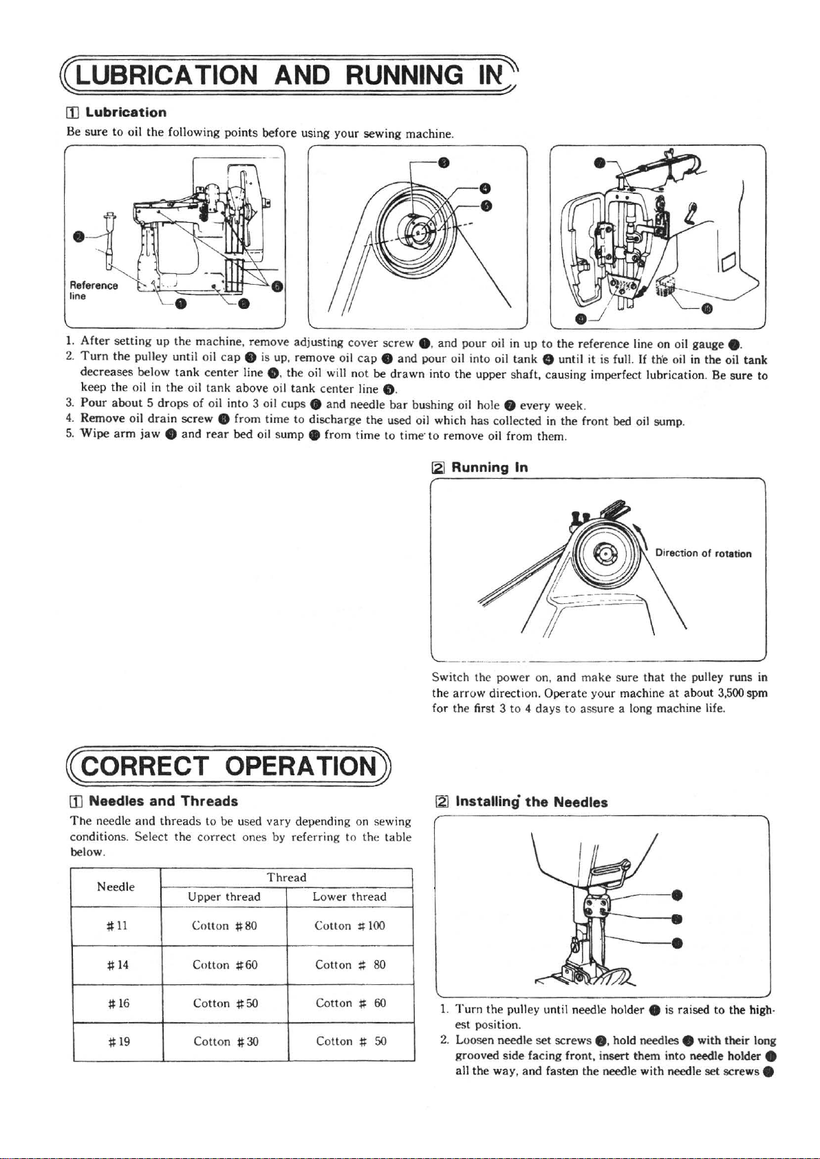
ill
lubrication
Be
sure
to
oil
the
1.
After
2.
Turn
decreases
keep
3.
Pour
Remove
4.
5.
Wipe
following
setting
the
the oil in
about 5 drops
arm
up
the
pulley until oil
below
tank
the
oil
drain
jaw e and
screw
machine
center
oil
tank
of
oil
rear
points
ca
into
e from
AND
before using
, remove adjusting
p e is
up
, remove oil
line e. the oil will
above
oil
tank
center
3 oil
cups e and
time
to
discharge
bed
oil
sump
e from
RUNNING
your
sewing machine.
cover
screw
e.
cap e and
not
be
line e.
needle
the
time
pour
drawn
into
bar
bushing oil hole e
used oil which
to time· to remove oil from them.
and
[21
IN~
pour
oil in
up
oil into oil
the
has
Running
tank
upper
shaft,
collected in
In
every
to
the
reference
0 until it is full.
causing imperfect lubrication. Be
week
.
the
front bed oil
line on oil gauge e.
If
th'e o
il
in
the
sump
.
oil
sure
tank
to
~CORRECT
!I]
Needles and Threads
The need
conditions.
below.
le
and
threads to
Select
the
Needle
~11
~
14
~
16 Cotton
~
19
OPERATION)
be
used vary depending on sewing
correct
Upper
Cotton
Cotton
Cotton # 30
ones
thread
~80
~60
~50
by
referring
Thread
Lower
Cotton
Cotton
Cotton ~ 60
Cotton ~ 50
to
the
thread
#
~
100
80
table
- -·-··
··--·-
Switch
the
for
the
arrow
the first 3 to 4
~
Installing
1.
Turn
the
es
t position.
2. Loosen needle
grooved side facing front, insert them i
all
the
---
power
on,
direction.
days
the
pulley until needle holder e is raised
set
way,
and
---·
and
make
Operate
your machine
to assure a long machine life .
Needles
scre
ws
e.
fasten
the
needle
---
sure
that
hold needles e with
with
-
----'
the
pulley runs in
at
about 3,500 spm
nto
needle holder e
needle
set
to
the
their
screws
high·
long
e
~3~
Page 8
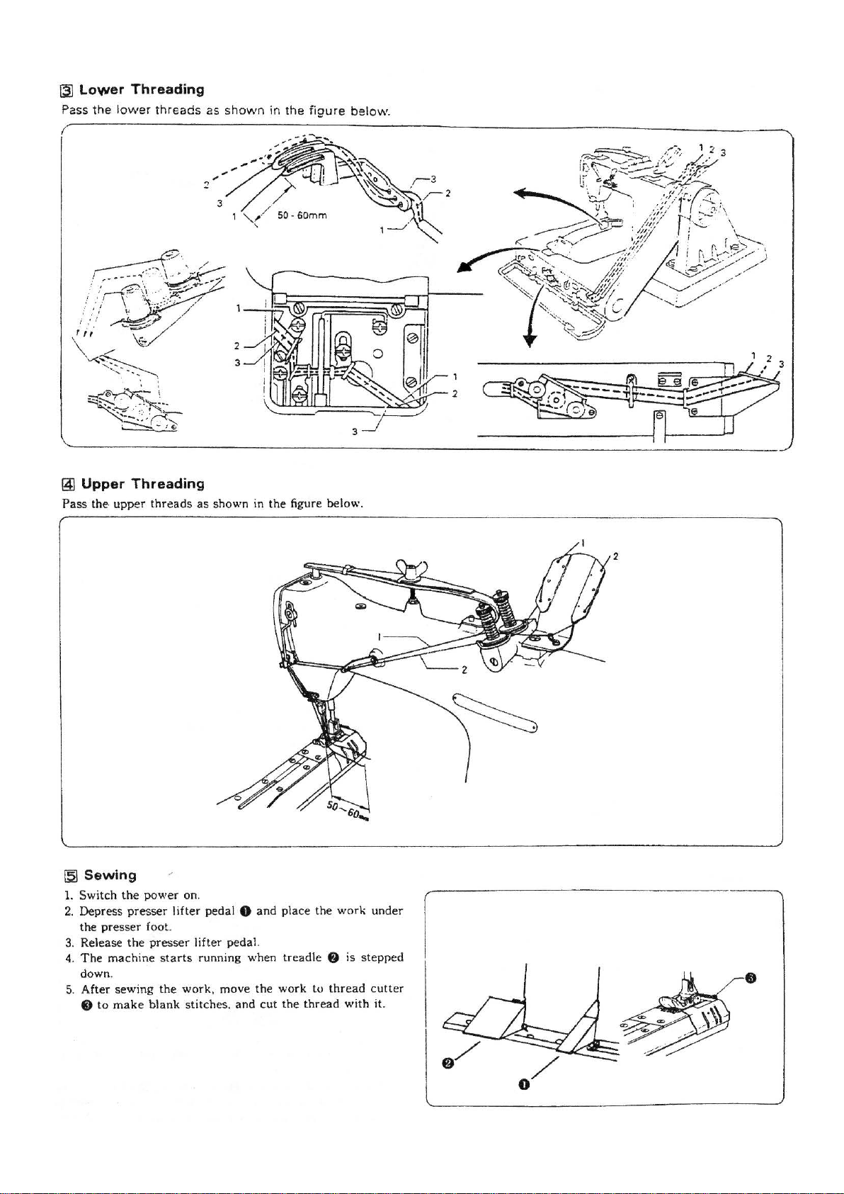
~
Pass
~
Pass
Lower
the lower
Upper
the· upper
Threading
threads
Threading
threads
as
as
shown
shown in
in
the
figure
the
figure below.
below.
~Sewing
1. Switch
2.
Depress
the presser foot.
3. Rele
4.
The
down.
5. After
the
presser
ase
the
machine starts
sewing the
fi)
to
make
power
lifter pedal 8
presser
work
blank
on.
and
place the
lifter pedal.
running when treadl e 8 is stepped
. move the
stitches.
and
work
cut the
to
thread
thread
work
with
under
cutter
it.
2
•
~4~
Page 9
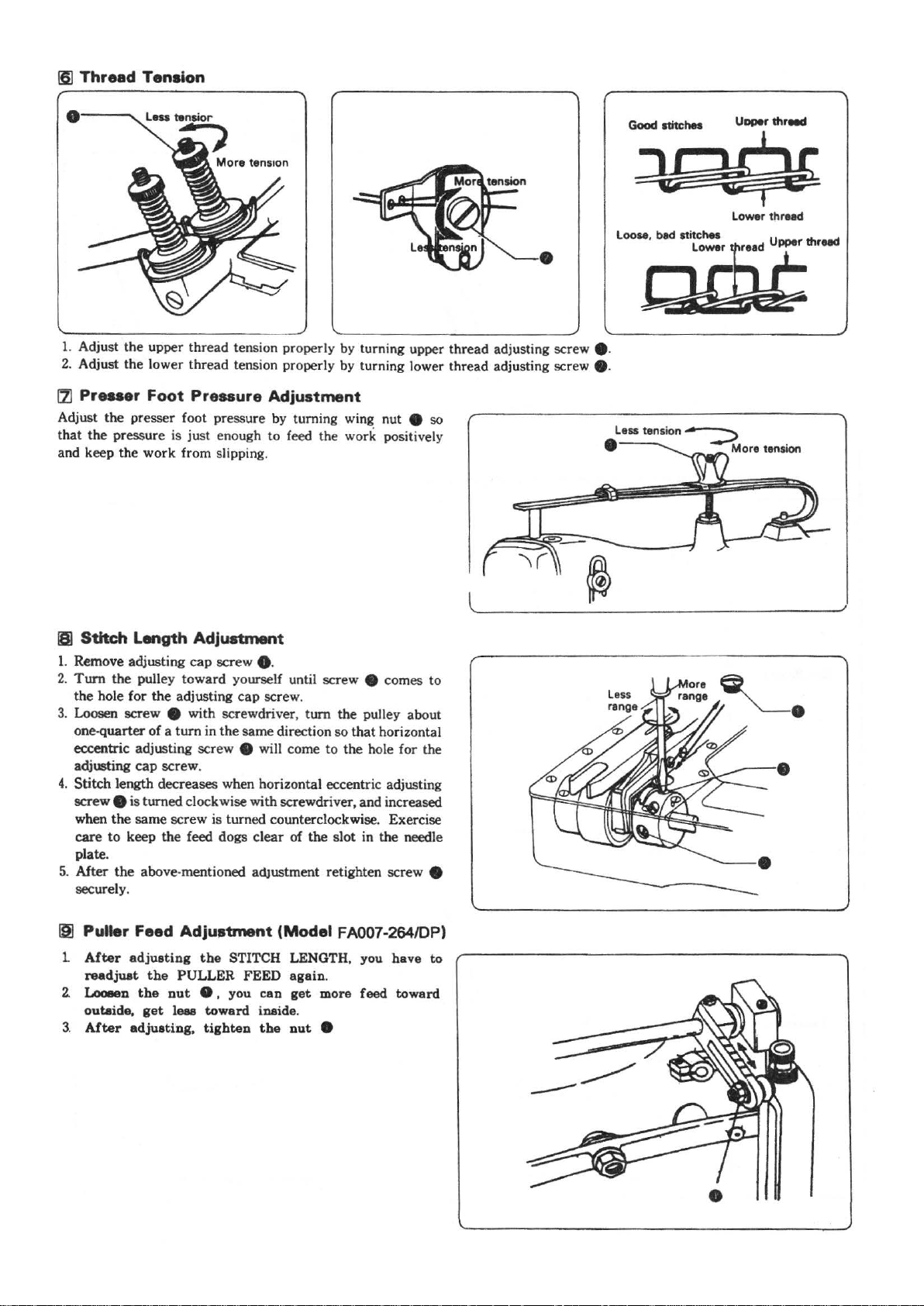
16]
Thread
Tension
Good
ltltchel
Uoper threed
1. Adjust
2.
121
Adjust the presser foot pressure by turning wing
that
and keep the work from slipping.
the
upper
thread
tension properly by turning upper thread adjusting screw e.
Adjust the lower
Pr
...
er
the pressure is just enough
Foot
thread
Pressure
tension properly by turning lower thread adjusting screw e.
Adjustment
to
feed the work positively
nut
e so
•
;y:
loose,
bad stitchel Upper thread
!&:~
lower
~
thread
181
Stitch
1.
Remove adjusting
2.
Turn
the hole
3.
Loosen screw e with screwdriver, turn the pulley about
one-quarter
eccentric adjusting screw
adjusting cap screw.
4.
Stitch length decreases when horizontal eccentric adjusting
screw
when
care
plate.
5.
After
securely.
IS]
Puller
1
After
readjuat
2.
Looeen
outaide,
3.
After
Length
the
for
pulJey
cap
toward
the
adjusting
of a turn
Adjustment
screw e.
yourself until screw e comes to
cap
screw.
in
the
same
direction
e wilJ come to
so
that
th
horizontal
e hole
for
e is turned clockwise with screwdriver, and increased
the
same
screw
is turned counterclockwise. Exercise
to
keep the feed dogs clear
the
above-mentioned adJustment retighten screw e
Feed
Adjustment
adjusting
the
the
get
adjusting,
the
STITCH LENGTH, you have to
PULLER FEED
out
8,
you cao
leas
toward
tighten
of
(Model
again
inaide.
the
out
the
slot
FA007-264/DP)
.
get
more
e
in the needle
feed
toward
the
~5~
Page 10
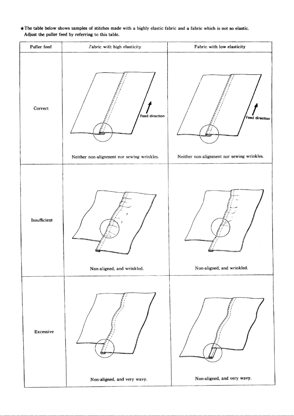
*The
Adjust
table
below shows samples
the
puller feed
Puller
feed
Correct
by
referring
of
stitches
to this table.
labric
made
with a highly elastic fabric and a fabric which
with high elasticity Fabric with low elasticity
is
not
so
elastic.
Insufficient
Neither non-alignment
Non
-aligned, and wrinkled.
nor
sewing wrinkles.
Neither non-alignment nor sewing wrinkles.
Non-aligned, and wrinkled .
Excessive
Non
-aligned,
and
very wavy.
~6~
Non-aligned, and very wavy.
Page 11
~STANDARD
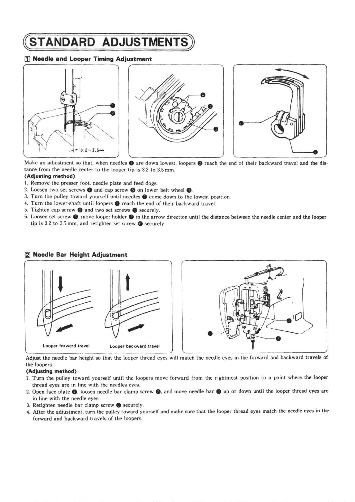
Make
an
adjustment so
tance
fr
om
the nee
(Adjusting
I.
Remove the presser foot, needle pl
2. Loosen
3.
Turn
Turn
4.
5.
Tight
6. Loosen
tip
m•thod)
two
set screws 8
the
pulley toward yourself until needles e come down
the lower-sh
en cap screw
set
screw
is 3.2
to
3.5 mm, and
that.
dle center
aft
until loopers 8 reach the end of their
e and
•.
move looper holder 8
ADJUSTMENTS)
when needles e
to
the
looper
ate
and
cap
screw e on lower belt wheel e.
two
set
screws 8 securely .
ret
ighten set screw • securely.
are
down lowest, loopers . reach the end of their backward
tip
is 3.2 to 3.5 mm.
and
feed d
in
the
ogs
arr
·---'
.
to
the lowest position.
bac
kward
travel.
ow direction until the distance between the needle cen
trav
el and the dis·
ter
and the looper
f2]
Needle Bar Height Adjustment
Looper
forward
Adju
st
the
needle bar height so
the
loopers.
(Adjusting
1.
Turn
thread
2.
Open face
in line with
3. Retighten needle
4.
After
forward and
m•thod)
the pulley
eyes
plate
the adjus
travel
that
toward your
are
in line with the needles eyes.
self until the loopers move forward from the rightmost position to a point where the looper
e. loosen needle
the nee
dle eyes.
bar clamp
tment, tum
backward
screw e sec urely.
the
pulley t
travels
of
Looper
backward
the looper thread eyes will
bar
clamp
owa
the loopers.
travel
screw e. and move need
rd yourself and·
mak
match
e sure
•
the needle
le
that
eyes
in the forward and backward travels of
bar
e up
or
the looper thread eyes
down until the looper thread eyes
mat
ch the needle eyes in the
are
~7~
Page 12
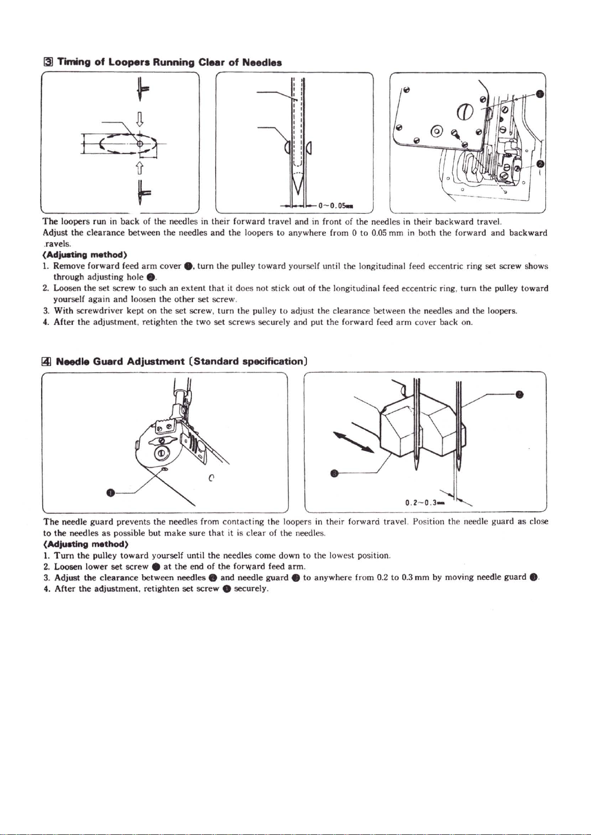
131
Timing
of
Loopers Running Clear
of
Needles
The
loopers run in
Adjust the
.ravel
(Adjusting
1.
Remove forward feed
thr
2.
Loosen the set screw to such
yourself
3. With scr
4.
After the adjustment. reti
~
Needle Guard Adjustment (Standard specification)
clearance
s.
method)
ough adjusting hole e.
again
ewdriver
back
of the needles in
between the needles
arm
cover e.
an
and loosen the
kept on the
ghten the
their
forward travel and in front of the needles in their
and
the
tum the pulley
extent
that
it does not stick out of the longitudinal feed eccentric ring, turn the pulley toward
other
set
screw
.
set
screw, turn the pulley
two
set
screws securely a
loopers to anywhere fr om 0 to
toward
0
,.,
-----
backward
0.05
mm
in
both the forward and
yourself until the longitudinal feed eccentric ring set screw shows
to
adjust the cl
nd
put
earance
the
forward feed
between the needl
arm
cover back on.
es
trave
l.
backward
and the loopers.
-----
·
The
needle gu
to
the
(Adjuatlng
1.
Turn
2. Loosen lower
3. Adjust the
4.
After
ard
needles
as
method)
the
pulley
clearance
the
adjustment, retighten
•
prevents
possible but
toward yourself until
set
the
needles from contacting the loopers
make
screw e at
between needles e and needle
sure
the end
set
screw
that
it
is
clear
the
needles come down
of
the forward feed
e securely.
of the needles.
to
arm
.
guard
e to anywhere
in
their forward travel. Position the needle guard as close
the lowest position.
fr
om 0.2
to
0.3 mm by moving needle guard 8 .
~8~
Page 13

(Puler ..,.cificetion)
The
clearance between the needles and the tips of the
be
0.05
mm,
loopers will
guard
•.
pushing the needles by needle
(Adju8ting
L
Turn
come down to the lowest position.
2.
Loosen
0 so
about
3.
Tum
of
4.
Loosen
left
between the needles
be
At
between the
in
l5J
Feed Dog Height Adjustment
Adjust the height of feed dog e so it
of
the
(Adjusting
Adjust the height of feed dog 8 by turning feed bar eccentric
shaft
Method)
the pulley toward yourself until the needles
stop
screw
e. and raise
that
the
bottom en
0.5
mm
above the bottom of needle guard e.
the
pulley toward yourself again until the tips
the
loopers come
stop
screw
or
to
the right, and adjust so
0.05
mm, pushing needle points by needle guard 8 .
this
time, please
the
backward
needle plate when feed dog 8
method)
loopers
movement
to
the centers of the needles.
e.
move needle guard 8 to the
and
make
and the needles is
or
lower needle guard
ds
of the needle eyes will be
that
the clearance
the tips of the loopers will
sure
that
the clearance
0.2-0.3
of
the loopers.
is
0.8 mm above the top
is
at
the highest position.
8
mm
--....:_.,
---...
..
O.OS..--1#-~0.2-0.J.
16)
Upper Thread
Adjust the height of the upper thread take·up thread guide
that, the upper
reaches the lowest point after the loopers run out
method)
the
upper
set
thread
s.
pulley
thread
screw e. and raise
guide e until
thread loop
(Adju.t
1.
Tum
of
2.
Loosen
up
Take-up
thread
will not be loose when the needle
toward
loops.
Thread Guide Adjustment
yourself until the loopers run
or
lower upper thread
it contact
s the upper
of
thread
upper
take
.
so
bar
out
·
~9~
Page 14
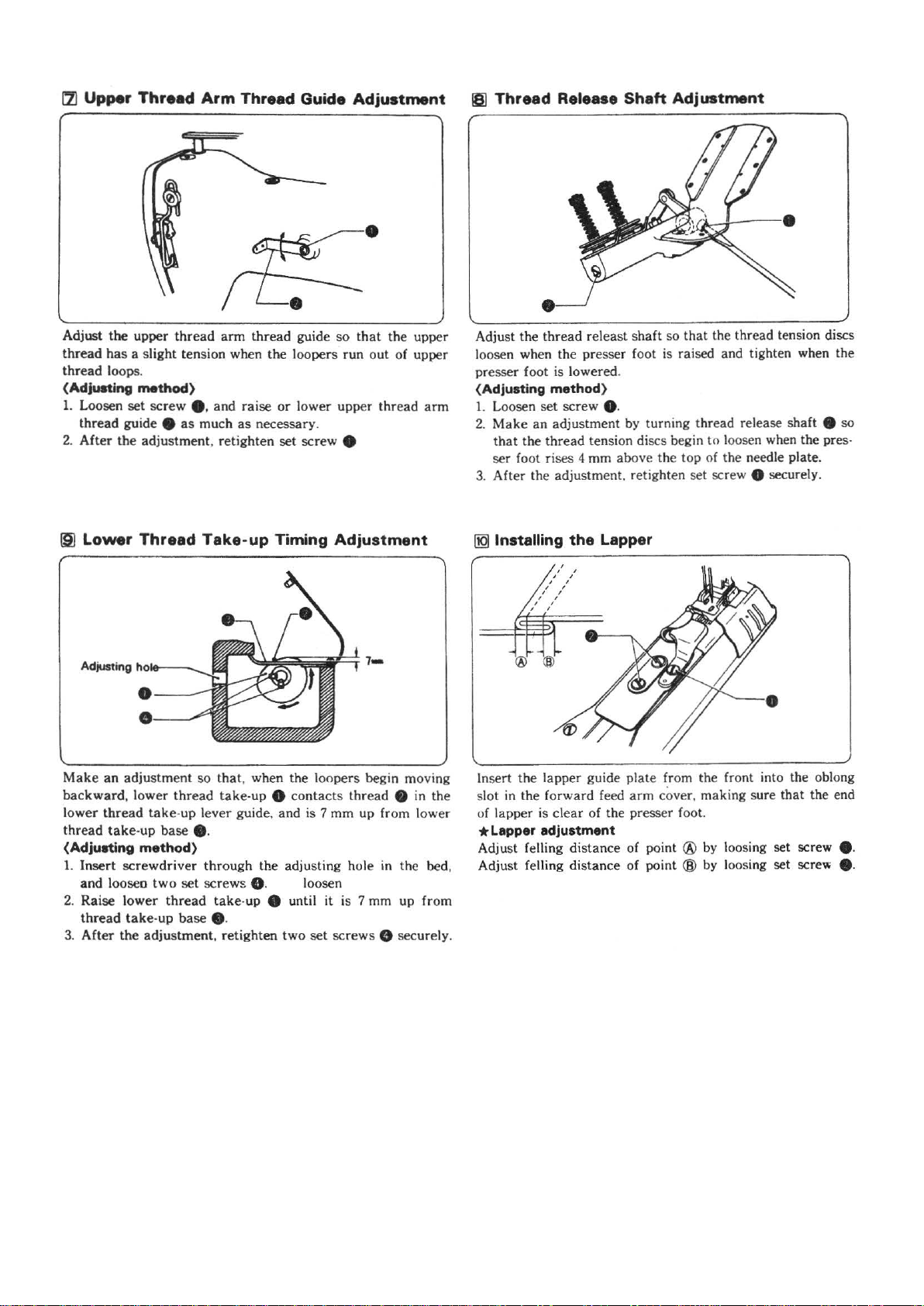
!7l
Upper
Adjust the upper
thread
thread
(Adjusting
1.
Loosen set screw e. and raise or lower upper thread
thread guide e
After
2.
19]
Lower
Thread
has
a slight tension when the loopers
loops.
method)
the
adjustment, retighten set screw e
Thread
Arm
thread
as
much
Take-up
Thread Guide
arm
thread guide
as
necessary.
Timing
Adjustment
so
that
run
out
Adjustment
the upper
of upper
arm
181
Thread
Adjust
loosen when the presser foot is raised and tighten when the
presser foot is lowered.
(Adjusting
1.
Loosen set screw e.
2.
Make
that
ser foot rises 4 mm above the top of the needle plate.
3.
After the adjustment, retighten set screw 8 securely.
[jQJ
Installing
Release
the
thread releast shaft so
method)
an adjustment by turning thread release shaft e so
the thread tension discs begin to loosen when the pres-
the
Shaft
Lepper
Adj
uatment
that
the thread tension discs
Make
an
adjustment so
backward,
lower
thread take-up
(Adjusting
1.
Insert
and
2. Raise
thread
3.
After
lower
thread
method)
screwdriver
looseo
lower
take
the
adjustment, retighten
that
, when
thread
take-up 8
take
-up lever guide, and is 7
base
e.
through
two
set screws Q. loosen
thread
-up
take-up 8 until it is 7 mm up from
base
e.
the
the
loopers begin moving
contact
s thread e in the
mm
up from lower
adjusting hole in the bed ,
two
set
screws 8 securely.
In
sert the tapper guide plate from the front into the oblong
slot in the forward feed
of lapper is clear of the presser foot.
arm
cover, making sure that the end
* Lapper adjustment
Adjust felling distance of point ®
Adjust felling distance of point ®
by
loosing set screw
by
loosing set screw e.
e.
~10~
Page 15

[llJ
Puller Height Adjustment (Model
Adjust the height
the
top
of
of
puller 0 so
the needle plate.
that
it is
927-S/M·PL)
0.1
to
0.2
mm high from
(AdjU8ting
Loosen
puller
~
Puller Device Timing Adjustment (Model FA007-264/DP)
1.
With
2.
The
needle ia
6mm,
3.
After
Method)
set
screw
8 is
0.1
3mm wrench
timing
and
adjusting
e.
and move puller support 8
to 0.2
mm
above the top
to
loosen
of
the
feed will be
away
from
the
needle
etoping
the
at
lOmm.
timing,
of
the needle plate.
the
screw
starting
plate
retighten
up
or
down until
8 & •
when
about 5 or
the
screw
the
0 • • .
0
~11~
Page 16

\(TROUBLESHOOTING)
J
ThrMd
Tro~
breHa.
I I CeuH
Needles installed improperly.
Upper
thread
ten
great.
Lower
thread
great.
thread
Upper
guide out of position.
Needle eyes too small for
threads.
Loopers damaged .
Needle groove
Needles hit loopers.
Wrong
timing of needles
and
loopers.
Needle hit loopers.
sion too
tension too
arm
damaged
thread
I
.__I
_IMpect_ion
Direction
Upper thread tension.
Lower thread tension.
Needle size
Damaged
.
Burrs in long groove.
Clearance between needles
and loopers.
Timing
loopers.
Clearance between needles
and needles guard.
of
long groove.
and
thread
of needles and
thread
way.
____,I
IL____~_Y
to
instructions for
Refer
needle installing.
Adjust upper thread
tension.
Adjust lower thread
tensio
n.
Adjust upper thread arm
thread guide.
Refer
to
the section on
'N
eedl
es
'
Replace loopers.
Replace needle.
Adjust timing of loopers
running clear of needles.
Adjust timing of Need les and
loopers.
Adjust needles guard.
and Threads"
_
_,__I
Page----...JI
Stnc:n.
lklp.
Needle eyes too small for
threads.
Needles installed improperly.
Looper points
Clearance between needles
and
loopers
Needle and looper timing
wrong.
Lower
timing wrong.
Upper
small.
Lower
great
.
Upper
2Uide
Feed dog
Presser
small.
are
too
thread
take·up
thread
tension
thread
tension too
thread
take
out
of
position.
too
low.
foot pressure
dull.
great.
·up
too
thread
too
Needle size and thread
Direction
Lower
timing.
Upper thread tension .
Lower thread tension.
Feed
Presser foot pressure.
thread
dog
of
long groove.
take·up
height.
Refer to the section
"Needles and Threads".
to
instructions for
Refer
needle installing.
Adjust timing of loopers
running clear of needles.
Adjust needle and looper
timing.
Adjust lower
timing.
Adjust upper thread tension.
Adjust lower thread tension .
Adjust upper thread take-up
thread guide position.
Adjust feed dog height.
Adjust presser foot pressu
thr
ead take·
on
UP
re
.
Mechlne
!Ia.
not fMd work.
Feed dog worn out.
Presser foot floats
not fully press work.
Feed dog and presser foot
work
on
one
and
side only.
f---
does
1------------------l
- - -
--
--------i
~12~
Have serviceman check it.
Have
serviceman check it.
Have seNiceman check them.
Page 17

Trouble
I
I
Puller timing
Puller feed incorrect. Puller feed.
Presser
incorrect.
Feed dog height incorrect. Feed dog height.
Cauee
wrong
foot
press~ae
I I
. Puller timing.
Preseer
IMpection
foot
press~ae
.
I I
Adilllt
puller device
A<liust
A<liust
pressure.
A<ljust
R...-cly
timq
puller feed.
preseer
foot
feed dog height.
I
.
Pea-
l
~13~
Page 18

Page 19

CONTENTS目錄
CO-MACHINE BODY
..................................................................1
機體下拉布輪
C1-UPPER SHAFT MACHANISM
...................................................3
上軸結構
C2-NEEDLE BAR MECHANISM-FEED MECHANISM
針柱與送布傳動結構
C3-PULLY MECHANISM
................................................................7
皮帶傳動結構
C4-PRESSER BAR MECHANISM
..................................................9
壓腳柱結構
C5-LOOPER MECHANISM
............................................................11
彎針傳動結構
.....................5
C6-UPPER THREADING MECHANISM
..........................................13
上導線張力結構
C7-LOWER THREADING MECHANISM
.........................................15
下導線張力結構
C8-LOWER SHAFT MECHANISM-GAUGE PARTS(SM1/4)
............17
下軸結構與針位組
C8-LOWER SHAFT MECHANISM-GAUGE PARTS(SM3/16)
下軸結構與針位組
C10-GAUGE PARTS (DP) DP
........................................................21
針位組
C11-PULLER DEVICE MECHANISM DP
.......................................23
上拉布輪結構
..........19
C12-ACCESSORIES
......................................................................25
配件
Page 20

B17
-1
()
[)_18
C 2
C0~1~
Page 21

MACHINE BODY
REF. NO.部件編號
C0-01
C0-C2
C0-5-1
C0-06
C0-07
C0-08
C0-09
C0-11
C0-11-1
C0-12-1
C0-12A
C0-B17-1
C0-A17-3
C0-17-3
C0-18
C0-X28-1
C0-X31
C0-X67
C0-X67-2
C0-X77
MACHINE HEAD 機體(上)
MACHINE REST BOARD 機體(下)
LOWER WHEEL 拉布輪
LOWER WHEEL CONNECTION 拉布輪軸
ONE WAY TRIANGULAR AXLE 單向三向軸片
ONE WAY STILL SPRING 單向彈簧
ONE WAY STILL BALL 單向滾珠
ONE WAY PUSHING PLATE 單向推輪
PIN 銷
FEED DOG PUSHING PLATE LINK 推輪連桿
SCREW 合葉螺釘
PULLER COVER 導蓋(右)
PULLER TOP COVER 護輪蓋
PACKING 導蓋
PLASTIC COVER 橡膠塞
SCREW 11/64×40 螺釘
SCREW 9/64×40 L8 螺釘
SCREW 3/32×56 螺釘
SCREW 3/32×56 L6 螺釘
SCREW 11/64×40 L9 螺釘
NAME OF PARTS 說明
Amt req需求量
1
1
1
1
2
6
6
1
1
1
1
1
1
1
2
2
3
3
3
2
~2~
Page 22

Y2
4
4-1
X38-1
X38-1
31
C1~3~
Page 23

UPPER SHAFT MACHANISM
REF. NO.部件編號
C1-01
C1-02
C1-03
C1-04
C1-04-1
C1-Y2
C1-C6
C1-07
C1-08
C1-09
C1-10
C1-11
C1-12
C1-13
C1-14
C1-15
C1-16
C1-17
C1-18
C1-18-1
C1-18-2
C1-18-3
C1-19
C1-21
C1-22
C1-22A
C1-23
C1-24
C1-25
C1-26
C1-27
C1-29
C1-30
C1-31
C1-102
C1-102-1
C1-X3
C1-X4
C1-X5
C1-X6
C1-X7
C1-X38-1
PULL BAR ENDING SCREW 合葉螺釘
VERTICAL PULL BAR 傳動連桿
PULL BAR BEARING 滾柱軸承
VERTICAL PULL BAR FIXING SCREW 合葉螺釘
WASHER 墊圈
PULL BAR SCREW NUT 止動螺母
UPPER SHAFT 上主軸
BALL BEARING 6202 軸承
BEARING SUPPORT 軸墊圈
OIL STOPPER 油封
BEARING CASE ASSEMBLY 軸套筒
BEARING 6302 軸承
OIL TANK 儲油器
OILGAUGE WINDOW 油鏡
PACKING 油封墊圈
OIL GAUGE FLANGE 儲油器蓋
OIL TANK PACKING 止油銅墊圈
PACKING 橡膠墊圈
UPPER WHEEL ECCENTRIC WHEEL 偏心凸輪
ECCENTRIC WHEEL WASHER 凸輪蓋
BEARING 滾柱軸承
SCREW 9/64×40 螺釘
UPPER WHEEL MOVING PULL BAR 凸輪傳動連桿
PULL BAR SCREW NUT 合葉螺釘
FIXING PULL BAR SCREW WASHER 止滑墊圈
WASHER 墊圈(薄)
PULL BARSCREW NUT 螺母
THICKNESS ADJUSTING PULL BAR 擺動傳桿
PULL BAR FIXING PULL BAR 螺釘
UPPER WHEEL CONNECTION 傳動軸
MOVABLE LEFT-RIGHT CHOCK RING 定位圈
CONNECTION COPPER TUBE 銅套筒
VERTICAL PULL BAR 雙頭合葉螺釘
WASHER 墊圈
BEARING FIXING SCREW 外牙螺母
BEARING FIXING BUSHING 緊壓套筒
SCREW 15/64×28 螺釘
SCREW 15/64×28 螺釘
SCREW 9/64×40 螺釘
CAP SCREW 覆蓋螺釘
SCREW 1/4×28 螺釘
SCREW 11/64×40 螺釘
NAME OF PARTS 說明
Amt req需求量
1
1
2
1
1
1
1
1
1
1
1
1
1
1
1
1
1
1
1
1
1
2
1
1
2
3
2
2
2
1
1
2
1
1
1
1
1
1
4
1
2
2
~4~
Page 24

X9
X7
X49
X8
C2~5~
X9
Page 25

NEEDLE BAR MECHANISM-FEED MECHANISM
REF. NO.部件編號
C2-01
C2-02
C2-03
C2-04
C2-05
C2-C6
C2-07
C2-08
C2-09
C2-10
C2-11
C2-C12
C2-14
C2-C15
C2-16
C2-17
C2-18
C2-C19
C2-20
C2-C21-1
C2-22
C2-23
C2-24
C2-C25
C2-26
C2-X7
C2-X8
C2-X9
C2-X10
C2-X14
C2-X31-1
C2-X49
NEEDLE BAR CRANK 固定軸
NEEDLE BAR CRANK BOD 提升連桿
NEEDLE BAR BRACKET 針柱夾
WICK 油蕊
OIL LEAK PROOF CAP 防油蓋
WICK 油蕊
NEEDLE BAR GUIDE SLIDE BLOCK 四方滑塊
NEEDLE BAR GUIDE 導軌
NEEDLE BAR 針柱
NEEDLE BAR BUSHING (U) 針柱套筒(上)
NEEDLE BAR BUSHING (D)針柱套筒(下)
THREAD TAKE-UP CRANK 平衡凸塊
OIL CAP 橡膠塞
NEEDLE 針
FEED DOG ECCENTRIC AXLE 調節凸輪
WASHER 墊圈
ECCENTRIC WHEEL SLEEVE 銅滑塊
ECCENTRIC WHEEL WITH SCREW 上下凸輪
ECCENTRIC WHEEL SLEEVE 銅滑塊
FEED BAR SLIDE BLOCK ASSEMBLY 送布傳動曲柄
PACKING 油封墊圈
FEED LIFTING FORK 叉動柄
FEED BAR SLIDE BLOCK ASSEMBLY 四方滑塊
FEED BAR ECCENTRIC SHAFT 偏心軸
FEED DOG ECCENTRIC SET 固定座
SCREW1/4×40 螺釘
SCREW11/64×40 L12 螺釘
SCREW 15/64×28 螺釘
SCREW 15/64×28 螺釘
FEED ECCENTRIC ADJUSTING SCREW 導位螺釘
SCREW 9/64×40 螺釘
SCREW 9/64×40 L5 螺釘
NAME OF PARTS 說明
Amt req需求量
1
1
1
1
1
1
1
1
1
1
1
1
1
2
1
1
1
1
1
1
1
1
1
1
4
4
5
2
1
1
1
1
~6~
Page 26

X7
C
X9
X1
X7
C
C3~7~
Page 27

PULLY MECHANISM
REF. NO.部件編號
C3-01
C3-02
C3-03
C3-C4
C3-C5
C3-06
C3-07
C3-08
C3-09
C3-10
C3-20
C3-X01
C3-X07
X3-X09
C3-X18
C3-X22
C3-X79
PULLEY 皮帶輪
TIMING BELT WHEEL ASSEMBLY (SUPPER) 同步皮帶輪(上)
TIMING BELT WHEEL ASSEMBLY (LOWER) 同步皮帶輪(下)
TIMING BELT 同步時規皮帶
BELT COVER 皮帶座
BELT COVER PLATE 皮帶座蓋板
PACKING 防油墊片
PULLEY COVER BASE 配重固定塊
PULLEY COVER 皮帶輪護蓋
WASHER 墊圈
SPRING COIL O型彈圈
SCREW1/4×28 螺釘
SCREW1/4×28 螺釘
SCREW1/4×28 螺釘
SCREW 15/64×28 螺釘
SCREW 7/16×14 螺釘
SCREW 3/16×32 L8 螺釘
NAME OF PARTS 說明
Amt req需求量
1
1
1
1
1
1
1
1
1
2
3
2
5
2
2
2
2
~8~
Page 28

(SM)
D2-27
C
X8
X95
X44
C4~9~
Page 29

PRESSER BAR MECHANISM
REF. NO.部件編號
C4-C1
C4-02
C4-03
C4-04
C4-05
C4-06
C4-07
C4-08
C4-09
C4-10
C4-11
C4-12
C4-13
C4-14
C4-15
C4-16
C4-17
C4-B18
C4-19
C4-20
C4-24
C4-X8
C4-X9
C4-X25
C4-X26
C4-X27
C4-X31
C4-X44
C4-X60
C4-X95
C4-Y02
C4-D2-27
PRESSR BAR 壓腳柱
FACE PLATE UPPER HINGE ASSEMBLY 蝶型後鈕
STEEL BALL 鋼珠
PRESSER BAR BUSHING (UPPER) 壓腳柱軸套(上)
PRESSER BAR BUSHING (LOWER) 壓腳柱軸套(下)
FACE PLATE (LOWER) 前蓋板(下)
PACKING 防油墊片
PRESSER BAR CLAMP ASSEMBLY 壓腳柱夾
PRESSER BAR CLAMP SPRING 壓力板
PRESSER BAR CLAMP SPRING PIN 定位銷
PRESSER BAR CLAMP SPRING ASSEMBLY 上壓力彈片
GUIDE WASHER 定向墊片
WING NUT 蝶型螺母
PRESSER BAR LIFTER 壓腳提放勾
KNEE LIFTER LEVER 壓腳提放柄
KNEE LIFTER SPRING 壓腳提放彈簧
PRESSER FOOT LIFTER CHAIN ASSEMBLY 傳動鏈條
FACE PLATE (UPPER) 前上蓋
STOPPER SPRING PLATE (L) 彈片勾(外)
STOPPER SPRING PLATE (S) 彈片勾(內)
OIP CAP 油塞
SCREW11/64×40 螺釘
SCREW 15/64×28 螺釘
PRESSER ADJUSTING SCREW 全牙螺釘
STUD SCREW 15/64×28 螺釘
STUD SCREW 5/16×28 螺釘
SCREW 9/64×40 L10 螺釘
SCREW 9/64×40 螺釘
SCREW 9/64×40 螺釘
SCREW 9/64×40 螺釘
NUT 3/16×32 螺母
RUBBER PLUR 橡膠塞
NAME OF PARTS 說明
Amt req需求量
1
1
1
1
1
1
1
1
1
1
1
1
1
1
1
1
1
1
1
1
1
1
1
2
1
1
3
4
1
1
1
1
~10~
Page 30

2
C29
X35
C14
C
C5~11~
21
Page 31

LOOPER MECHANISM
REF. NO.部件編號
C5-02
C5-C3
C5-C4
C5-C5
C5-06
C5-C7
C5-C8
C5-09
C5-10
C5-C11
C5-12
C5-C13
C5-A14
C5-C15
C5-16
C5-17
C5-C18
C5-C19
C5-20
C5-21
C5-22
C5-23
C5-25
C5-C26
C5-27
C5-C28
C5-C29
C5-C30
C5-C31
C5-32
C5-33
C5-702
C5-X9
C5-X28
C5-X28-1
C5-X31
C5-X32
C5-X34
C5-X35
C5-X36-1
C5-X37
C5-X38-1
C5-X42
C5-X50
C5-X56
C5-Y01
ECCENTRIC WHEEL SLEEVE 銅滑塊
LOOPER FEEDING FORK 滑動叉
LOOPER FEEDING SHAFT 滑動叉(軸)
LOPPER FEEDING SHAFT BRACKET 滑動叉基座
PIN 插銷
LOOPER FRONT-REAR TRANSMISSION 前後驅動連桿
SLIDE BROCK SHAFT 固定軸牙
LOOPER LEVER SHAFT 雙節固定軸
PACKING 墊圈
CONNECTING ROD GUIDE PLATE 上下驅動連桿
WASHER 墊圈
LOOPER SHAFT CLAMP 傳動軸夾
LOOPER SHAFT 傳動軸
LOOPER SHAFT BUSHING (F) 傳動軸套筒(後)
LOOPER SHAFT BUSHING (B) 傳動軸套筒(前)
SET COLLAR 定位夾
FORWARD ARM CONER ASSY 平面蓋板
PACKING 防油墊片
OIL GAUGE 探油棒
PACKING 橡膠墊圈
CAP PLATE 下軸蓋
PACKING 防油墊片
"8"TYPE TRANSMISSION DEVICE 8字銅連桿
ECCENTRIC WITH SCREW 小凸輪
EYEPIECE H型連桿
STEEL BALL 萬向滾珠
LOOPER SLIDE BASE 連桿固定片
WASHER 波浪彈片
LOOPER FEEDING FORK 叉動柄
--
-SQUARE BALL 四方滑塊
SCREW 15/64×28 螺釘
SCREW 11/64×40 螺釘
SCREW 11/64×40 螺釘
SCREW 11/64×40 螺釘
電
SCREW 11/64×40 螺釘
SCREW 3/16×32 螺釘
SCREW 3/32×56 螺釘
SCREW N3.5 L10 螺釘
SCREW 11/64×40 螺釘
SCREW 11/64×40 螺釘
SCREW 1/2×28 螺釘
SCREW 9/64×40 L5 螺釘
SCREW 15/64×28 螺釘
NUT 15/64×28 螺母
NAME OF PARTS 說明
Amt req需求量
1
1
1
1
1
1
1
1
1
1
1
1
1
1
1
1
1
1
1
3
1
1
1
1
1
1
1
1
1
1
1
1
2
1
1
16
2
1
2
4
1
2
3
4
2
1
~12~
Page 32

(SM)B26
(PL)
7-1
X34-1
C
X9
X31-1
X50
B40
C6~13 ~
Page 33

UPPER THREADING MECHANISM
REF. NO.部件編號
C6-01
C6-06
C6-C7
C6-7-1
C6-08
C6-09
C6-10
C6-11
C6-12
C6-C13
C6-14
C6-C15
C6-18
C6-C19
C6-C21
C6-C22
C6-25
C6-26
C6-B26
C6-C32
C6-33
C6-C34
C6-37
C6-38
C6-B39
C6-B40
C6-X08
C6-X09
C6-X31-1
C6-X34-1
C6-X44
C6-X47
C6-X48
C6-X50
C6-X53
C6-X58
C6-X59
C6-X65
C6-Y04
UPPER THREAD GUIDE RETAINER 上導線座
THREAD HANGER 導線圈
LINE GUIDE DEVICE 導位基座
PIN 銷
TENSION SPRING WASHER 彈簧墊圈
TENSION SPRING WASHER 彈簧墊圈
NUT 螺母
TENSION DISC 沙拉片
TENSION DISE PRESSER 張力墊圈
UPPER THREAD TENSION SPRONG 張力彈簧
UPPER THREAD RELEASE PIN 銷
THREAD RELEASER SHAFT 轉軸
UPPER THREAD TENSION SUTD SCREW 過線固定片
UPPER THREAD TAKE-UP GUIDE 天秤過線
UPPER THREAD ARM GUIDE 鬆放過線
THREAD TAKE-UP COVER 天秤護蓋
TENSION RELEASE CRANK 連桿
TENSION RELEASE CONNECTING ROD 上線鬆放提柄
TENSION RELEASE CONNECTING ROD 上線鬆放提柄
THREAD GUIDE TAKE-UP GUIDE 導線鉤
WASHER 墊圈
UPPER THREAD TAKE-UP ASSY 天秤
LOWER THREAD GUIDE 導線勾(D)
WASHER 墊圈
LOOPER THREAD GUIDE BAACKET 固定圈
RUBBER PLUG 橡膠塞
SCREW 9/64×40 螺釘
SCREW 15/64×28 螺釘
SCREW 11/64×40 螺釘
SCREW 3/16×32 螺釘
SCREW 9/64×40 螺釘
SCREW 11/64×40 螺釘
SCREW 9/64×40 螺釘
SCREW 9/64×40 螺釘
SCREW 9/64×40 螺釘
UPPER THREAD TENSION STUD SCREW 叉口合葉螺釘
SCREW 3/16×32 螺釘
SCREW 3/32×56 L4 螺釘
NUT 11/64×40 螺母
NAME OF PARTS 說明
Amt req需求量
1
1
1
1
2
2
2
4
2
2
1
1
2
1
2
1
1
1
1
1
1
1
1
2
1
1
1
1
1
2
1
1
2
1
1
2
1
1
3
~14~
Page 34

C2N
X92
X67-1
X44
X9
PL
X31-1
47-1
X31-1
A55
X9 5
X31-1
2
X31-2
C7~15 ~
Page 35

LOWER THREADING MECHANISM
REF. NO.部件編號
C7-01
C7-C2N
C7-3N
C7-06
C7-12
C7-12-1
C7-17
C7-A10
C7-A11
C7-A12
C7-A14
C7-A14-1
C7-A17
C7-A18
C7-A55
C7-C20-B
C7-C22-B
C7-C23-B
C7-C25-B
C7-27
C7-28
C7-29
C7-30
C7-31
C7-32
C7-33
C7-34
C7-35
C7-36
C7-37
C7-39
C7-40
C7-41
C7-44
C7-45
C7-46
C7-47-1
C7-48
C7-49
C7-53
C7-A50-2
C7-A50-3
C7-A50-4
C7-A51-4
C7-B50
C7-B51
C7-C68
C7-X5
C7-X9
C7-X31電
C7-X31-1
C7-X31-2
C7-X44
C7-X45
C7-X50
C7-X60
C7-X64
C7-X65
C7-X66
C7-X67-1
C7-X92
C7-X95
C7-Y05
LOERT THREAD GUIDE RETAINER 導線架(上)
THREE PIPE-LINE THREAD TUBE 過線管
THREAD TUBE CLAMP 導線圈
LOWER THREAD GUIDE SUPPORTER 支架輔助
LOWER THREAD GUIDE HINGE ASSEMBLY 活動鈕(上)
LOWER THREAD GUIDE HINGE ASSEMBLY 活動鈕插銷
LOWER THREAD COVER 橡膠墊
LOWER THREAD COVER 下前蓋
PLATE SPRING 彈片勾
FIXING PLATE 活動鈕(下)
LOWER THREAD TENSION BRACKET 三通過線片
THREAD GUIDE 穩線片
LOWER THREAD GUIDE RETAINER ?通過線片
PLATE SPRING 彈片勾
LOWER THREAD GUIDE 過線片
THREAD TENSION ROD 沙拉螺柱
LOWER TEREAD TENSION NUT 沙拉螺母
LOWER TEREAD TENSION PLATE 沙拉片
LOWER TEREAD TENSION SPRING 沙拉彈簧
THREAD TAKE-UP LEVER COVER 護線蓋
SPRING 彈簧勾
LOWER THREAD TAKE-UP LEVER FRAME 過線輔助架
LOWER THREAD TAKE-UP LEVER COVER SHAFT 銷
LOWER THREAD TAKE-UP LEVER BASE 過線支架
GUIDE PLATE 過線輔助架
WASHER 墊圈
LOERT THREAD GUIDE PLATE 固定片
SCREW 彈簧
WASHER 墊圈
LOWER THREAD GUIDE(LEFT) 彈片扣
LOWER THREAD GUIDE(LEFTRIGHT) 導線勾
LOWER THREAD GUIDE(LEFT) 導線勾
LOWER THREAD GUIDE PLATE 固定片
LOWER THREAD TAKE-UP DISC ASSEMBLY 配線凸輪
LOWER THREAD FEED TUBE 過線管
LOOPER THREAD GUIDE RACKET 針受座
LOOPER THREAD GUIDE BRACKET 針受座
THREAD CUTTER GUIDE PLATE 切線刀
THREAD CUTTER 切線刀
LOOPER GUIDE 過線片
STOPPER SPRING PLATE 彈片勾
PIN 銷
FACE PLATE UPPER HINGE ASSEMBLY(R) 蝴蝶後扭(右)
FACE PLATE UPPER HINGE ASSEMBLY(L) 蝴蝶後扭(左)
LOOPER SIDE COVER (R) ASSY 彎針護蓋
LOOPER SIDE COVER (L) ASSY 彎針護蓋
PIN 銷
SCREW 9/64×40 螺釘
SCREW 15/64×28 螺釘
SCREW 11/64×40 螺釘
SCREW 11/64×40 螺釘
SCREW 9/64×40 L10 螺釘
SCREW 9/64×40 L5 螺釘
SCREW 9/64 螺釘
SCREW 9/64 螺釘
SCREW 9/64×40 L4 螺釘
SCREW 3/32×56 螺釘
SCREW 3/32×56 L4 螺釘
SCREW 1/4×40 螺釘
SCREW 3/32×56 螺釘
SCREW 9/64×40 螺釘
SCREW 9/64×40 螺釘
NUT 9/64×40 螺母
NAME OF PARTS 說明
Amt req需求量
1
1
4
1
1
2
2
2
2
1
2
2
1
1
1
2
1
2
2
4
2
1
1
1
1
1
1
2
1
1
2
1
1
1
1
1
1
1
1
1
2
4
1
1
1
1
1
1
1
3
12
2
7
2
2
1
3
2
2
6
1
1
2
~16~
Page 36

SM1/4
X3
X93
C10-1B
X31
C14-1B
X49
C8~17 ~
Page 37

LOWER SHAFT MECHANISM-GAUGE PARTS
REF. NO.部件編號
C8-C1
C8-02
C8-03
C8-04
C8-05
C8-06
C8-C7-1B
C8-C8-1B
C8-C9-1B
C8-C10-1B
C8-11
C8-C13-1B-1
C8-C13-1B-2
C8-C13-1B-3
C8-C13-1B-4
C8-C14-1B
C8-C16-1B
C8-C17-1B
C8-C18
C8-C19
C8-102
C8-X3
C8-X8
C8-X31
C8-X32
C8-X49
C8-X50
C8-X74-1
C8-X75
C8-X77
C8-X78
C8-X79
C8-X82
C8-X83
C8-X93
LOVER SHAFT 下主軸
BEARING 6200 Z 軸承
BEARING 6201 Z 軸承
BALL BEARING BUSHING 內套筒
BEARING CASE ASSEMBLY 軸套筒(下)
BEARING FIXING BUSHING 緊壓套筒
NEEDLE CLAMP WITH SCREW 1/4 針夾
NEEDLE PLATE 1/4 針板
PRESSER FOOT ASSEMBLY 1/4 壓腳組
FEED DOG 1/4 送布齒
BEARING 6302 軸承
NEEDLE GUARD 針受座
NEEDLE GUARD 針受座(右)
NEEDLE GUARD 針受座(左)
NEEDLE GUARD 針受座(中)
LAPPER ASSY 1/4 導布架
LOOPER 1/4 彎針
LOOPER 1/4 彎針
LOOPER HOLDER 彎針座
LOOPER HOLDER 彎針座
BEARING FIXING SCREW 外牙螺母
SCREW 5/16×28 螺釘
SCREW 9/64×40 螺釘
SCREW 9/64×40 螺釘
SCREW 11/64×40 螺釘
SCREW 9/64×40 螺釘
SCREW 9/64×40 螺釘
SCREW 1/4×28 螺釘
SCREW 11/64×40 螺釘
SCREW 11/64×40 螺釘
SCREW 9/64×40 螺釘
SCREW 3/16×32 螺釘
SCREW 9/64×40 螺釘
SCREW 11/64×40 螺釘
SCREW 11/64×40 螺釘
NAME OF PARTS 說明
Amt req需求量
1
1
1
1
1
1
1
1
1
1
1
1
1
1
1
1
1
1
1
1
1
1
2
1
2
1
1
1
1
2
3
1
1
2
2
~18~
Page 38

SM3/16
X3
X93
C10-2B
C7-2B
C14-2B
C8-2B
X31
C17-2B
C16-2B
C9-2B
X49
C8~19 ~
Page 39

LOWER SHAFT MECHANISM-GAUGE PARTS
REF. NO.部件編號
C8-C1
C8-02
C8-03
C8-04
C8-05
C8-06
C8-C7-2B
C8-C8-2B
C8-C9-2B
C8-C10-2B
C8-11
C8-C13-1B-1
C8-C13-1B-2
C8-C13-1B-3
C8-C13-1B-4
C8-C14-2B
C8-C16-2B
C8-C17-2B
C8-C18
C8-C19
C8-102
C8-X3
C8-X8
C8-X31
C8-X32
C8-X49
C8-X50
C8-X74-1
C8-X75
C8-X77
C8-X78
C8-X79
C8-X82
C8-X83
C8-X93
LOVER SHAFT 下主軸
BEARING 6200 Z 軸承
BEARING 6201 Z 軸承
BALL BEARING BUSHING 內套筒
BEARING CASE ASSEMBLY 軸套筒(下)
BEARING FIXING BUSHING 緊壓套筒
NEEDLE CLAMP WITH SCREW 3/16 針夾
NEEDLE PLATE 3/16 針板
PRESSER FOOT ASSEMBLY 3/16 壓腳組
FEED DOG 3/16 送布齒
BEARING 6302 軸承
NEEDLE GUARD 針受座
NEEDLE GUARD 針受座(右)
NEEDLE GUARD 針受座(左)
NEEDLE GUARD 針受座(中)
LAPPER ASSY 3/16 導布架
LOOPER 3/16 彎針
LOOPER 3/16 彎針
LOOPER HOLDER 彎針座
LOOPER HOLDER 彎針座
BEARING FIXING SCREW 外牙螺母
SCREW 5/16×28 螺釘
SCREW 9/64×40 螺釘
SCREW 9/64×40 螺釘
SCREW 11/64×40 螺釘
SCREW 9/64×40 螺釘
SCREW 9/64×40 螺釘
SCREW 1/4×28 螺釘
SCREW 11/64×40 螺釘
SCREW 11/64×40 螺釘
SCREW 9/64×40 螺釘
SCREW 3/16×32 螺釘
SCREW 9/64×40 螺釘
SCREW 11/64×40 螺釘
SCREW 11/64×40 螺釘
NAME OF PARTS 說明
Amt req需求量
1
1
1
1
1
1
1
1
1
1
1
1
1
1
1
1
1
1
1
1
1
1
2
1
2
1
1
1
1
2
3
1
1
2
2
~20~
Page 40

PL
X32
X31
X8
C14-2B
C14-3
C14MH
X8
C10~21~
Page 41

GAUGE PARTS(DP)
REF. NO.部件編號
C10-C7-1
C10-C7-2
C10-C7-3
C10-C8-1
C10-C8-2
C10-C8-3
C10-C9-1
C10-C9-2
C10-C9-3
C10-C10-1
C10-C10-2
C10-C10-3
C10-C12
C10-C13
C10-C14MH
C10-C14-2B
C10-C14-3
C10-C16-1
C10-C16-2
C10-C16-3
C10-C17-1
C10-C17-2
C10-C17-3
C10-C18
C10-C19
C10-X8
C10-X31
C10-X32
C10-X77
C10-X79
C10-X82
C10-X83
NEEDLE CLAMP EITH SCREW 1/4 針夾
NEEDLE CLAMP EITH SCREW 3-16 針夾
NEEDLE CLAMP EITH SCREW 1/8 針夾
NEEDLE PLATE 1/4 針板
NEEDLE PLATE 3/16 針板
NEEDLE PLATE 1/8 針板
PRESSER FOOT ASSY 1/4 壓腳組
PRESSER FOOT ASSY 3/16 壓腳組
PRESSER FOOT ASSY 1/8 壓腳組
FEED DOG 1/4 送布齒
FEED DOG 3/16 送布齒
FEED DOG 1/8 送布齒
FINGER GUARD 針受
NEEDLE GUARD 針受
LAPPER ASSY 導布架喇叭
LAPPER ASSY 導布架喇叭
LAPPER ASSY 導布架喇叭
LOOPER 1/4 彎針
LOOPER 3/16 彎針
LOOPER 1/8 彎針
LOOPER 1/4 彎針
LOOPER 3/16 彎針
LOOPER 1/8 彎針
LOOPER HOLDER 彎針台
LOOPER HOLDER 彎針台
SCREW 11/64×40 螺釘
SCREW 9/64×40 螺釘
SCREW 9/64×40 螺釘
SCREW 11/64×40 螺釘
SCREW 3/16×32 螺釘
SCREW 9/64×40 螺釘
STUD SCREW 螺釘
NAME OF PARTS 說明
Amt req需求量
1
1
1
1
1
1
1
1
1
1
1
1
1
1
1
1
1
1
1
1
1
1
1
1
1
2
1
2
3
1
1
2
~22~
Page 42

PL
9A
D1-9
X9
10
X67-1
14
C20
15
12
X67-2
9
C11~23~
Page 43

PULLER DEVICE MECHANISM
REF. NO.部件編號
C11-01
C11-02
C11-03
C11-05
C11-06
C11-07
C11-08
C11-09
C11-9A
C11-10
C11-12
C11-14
C11-15
C11-17
C11-A18-1
C11-C20
C11-X9
C11-X19
C11-X67-1
C11-X67-2
C11-D1-9
PRESSURE ADJUSTING SCREW 外牙螺母
UPPER WHEEL PRESSER BAR 立軸
SPRING 張力彈簧
WHEEL DIRECTION FIXING DEVICE 拉布輪壓力提柄
FRESSER ROD BUSHING 軸套
UPPER WHEEL SEAT 拉布輪架
UPPER WHEEL CONNECTON 固定軸
ONE WAY PULL HOLDER 拉柄
SCREW 螺釘
PACKING 防油墊片
ONE WAY TRIANGULAR WHEEL 單向三角軸片
ONE WAY STILL BALL 單向滾珠
ONE WAY STILL SPRING 單向彈簧
CHOCK RING E型扣環
FACE PLATE (UPPER) DP上前蓋座
UPPER WHEEL 拉布輪(上)
SCREW 15/64×40 螺釘
SCREW 15/64×40 螺釘
SCREW 3/32×56 螺釘
SCREW 3/32×56 螺釘
BUBBER 橡膠塞
NAME OF PARTS 說明
Amt req需求量
1
1
1
1
1
1
1
1
4
1
2
6
6
1
1
1
1
1
3
3
4
~24~
Page 44

16
8
2-1
C1
C12~25~
Page 45

ACCESSORIES
REF. NO.部件編號
C12-C1
C12-02
C12-2-1
C12-03
C12-04
C12-05
C12-06
C12-07
C12-08
C12-09
C12-10
C12-11
C12-12
C12-13
C12-14
C12-16
C12-X1
C12-X2
THREAD STAND 四葉線架
CUSHION ASSEMBLY 固定座
WASHER 墊圈
BASE CUSHION 橡膠墊塊
HEAD COVER 防塵套
OIL TANK 大油壺
OILER ASSEMBLY 小油瓶
NEEDLE 針
TWEEZERS 線夾
SPANNER 固定板手(#7)
SPANNER 固定板手(#8)
SCREW DRIVER 大起子
SCREW DRIVER 小起子
SCREW DRIVER 中起子
THREADLE 腳踏板
SPANNER 固定板手(#10)
SCREW1/4×28 螺釘
SCREW 6.2×26 木螺釘
NAME OF PARTS 說明
Amt req需求量
1
2
2
2
1
1
1
5
1
1
1
1
1
1
2
1
2
2
~26~
Page 46

Sir:tUaA
TABLE
CUT-OUT
750
725
Series
Item Code
FA007 FA007-T1
I
!
\
:
~
---------
0
0
co
..-i
om
com
(\J(\J
r
Subclass I Remark
• FOR FA007 Series
L()
co
(Y)
012
L()
(Y)
L()
Mounting
Fully-submerged
Date
2014 I 7 I 18
f+1>
~
~
-jmg
~
~
~!CF
~
~
;;;o""'
~
lt
"@
n
0
4~
\:':
'-
I--<
/'--j
Am3
""'3
~
- =
~
~
~ln~
§j
D~
~
~
~
fQ
I+
[\)
~
-¥=
680
210 4-R10
.~b------+-~~v---t--t-
g -
-------
-----
--
520
026
~
..
lrl
..
08.5
A-A
:§iJtm
017
-f=-r--
85
o--~~----~--------------------------~r---~-~---0
L()
co
0
 Loading...