

Page 1
® '
J
•
15f!ffl
INSTRUCTION
IDt~
i!i
&
~
~
®
~
**
KAULIN
]
~
151
MFG.
&~ftf~
PARTS
~
~N
~
CO., L TO
BOOK
PJ
.
Page 2
~I
I N D E X
J!{
/PAGE
{!Jij~IJJ
.
:t(.
..
~
• •
. II
tl
.Rti~2J!tl
·
·~112J!tl
.at.&t2~1J-IItl
.at2J!
.!J
ji
.
at~
·
~···
.J:J(
.jq~Az
.!1~-flJl;ZJilt
.ji¥ARI1J~Jl2
·~
·
fi-~IJJ
..
at
••
.at-~at;Z~ift·~
.~at~••z••
. ill
JJ{
.
fi
JJ{
.~f5JAiflJliilt
.
~
f5J
.J:Jt
.J:J(
.jq~Af17t2illl
.at
-~atillfifJIJ~ruJ
Jt
m
tl
1Jl!
• ·
tt
2
••
~-t!Jiilt
il~t
~
·
rlll
Jlil.
at
J=l
•
ll
at
J=l
• •
AM
.fiiiiW
fjflJill
j!f
illt
2
illl
it.2iill
. ~
at
ft1J
• •
.~at-W
JJJ
fi2iilt
OPERATION
GUIDE
.INSTALLATION
.MOTOR
AND
BELT
.LUBRICATION
.HOW
.HOW
.LUBRICATING
.HOW
TO
CHANGE
TO
REPLACE
TO
REPLACE
THE
.THREADING
.ADJUSTING
.ADJSUTING
.ADJUSTING
.ADJUSTING
.
ADJUSTING
.ADJUSTING
.ADJUSTING
MAINTENANCE
.THE
HEIGHT
.TIMING
.ADJUSTING
.ADJUSTING
.ADJUSTING
.
ADJUSTING
.ADJUSTING
.SETTING
THREAD
.
ADJUSTING
.ADJUSTING
THREAD
NEEDLE
SPREADER
PRESSER
STITCH
DIFFERENTIAL
THE
GUIDE
OF
OF
NEEDLE
THE
THE
THE
THE
THE
THE
POSITION
GUIDE
THE
PRESSER
.ADJUSTMENTING
AND
LOOPER
.ADJUSTING
.ADJUSTING
THE
THE
OIL
THE
THE
OIL
FILTER
NEEDLES
NEEDLES
AND
TENSION
THREAD
TAKE-UP
THREAD
FOOT
LENGTH
RATIO
PRESSURE
NEEDLE
AND
LOOPER
FRONT
REAR
NEEDLE
HEIGHT
FEEDING
OF
BAR
LOOPER
THREAD
NEEDLE
OF
FEED
TILT
OF
SPREADER
SPREADER'S
FOOT
THE
TIMING
LOOPER'S
LOOPER
LIFT
MOTION
THREAD
THREADS
TAKE-UP
PRESSER
TAKE-UP
GUARD
GUARD
DOG
STROKE
OF
NEEDLE
GUIDES
FOOT
1
2
2
3
3
3
3
4
4
5
5
6
6
7
7
8
8
11
11
12
12
13
15
15
16
17
17
17
SPARE
PARTS
LIST
-~·
•m~
•~t•
SPARE
TABLE
PARTS
CONVERSION
CUT-OUT
CHART
18-33
34
35-37
Page 3
OPERATION
GUIDE
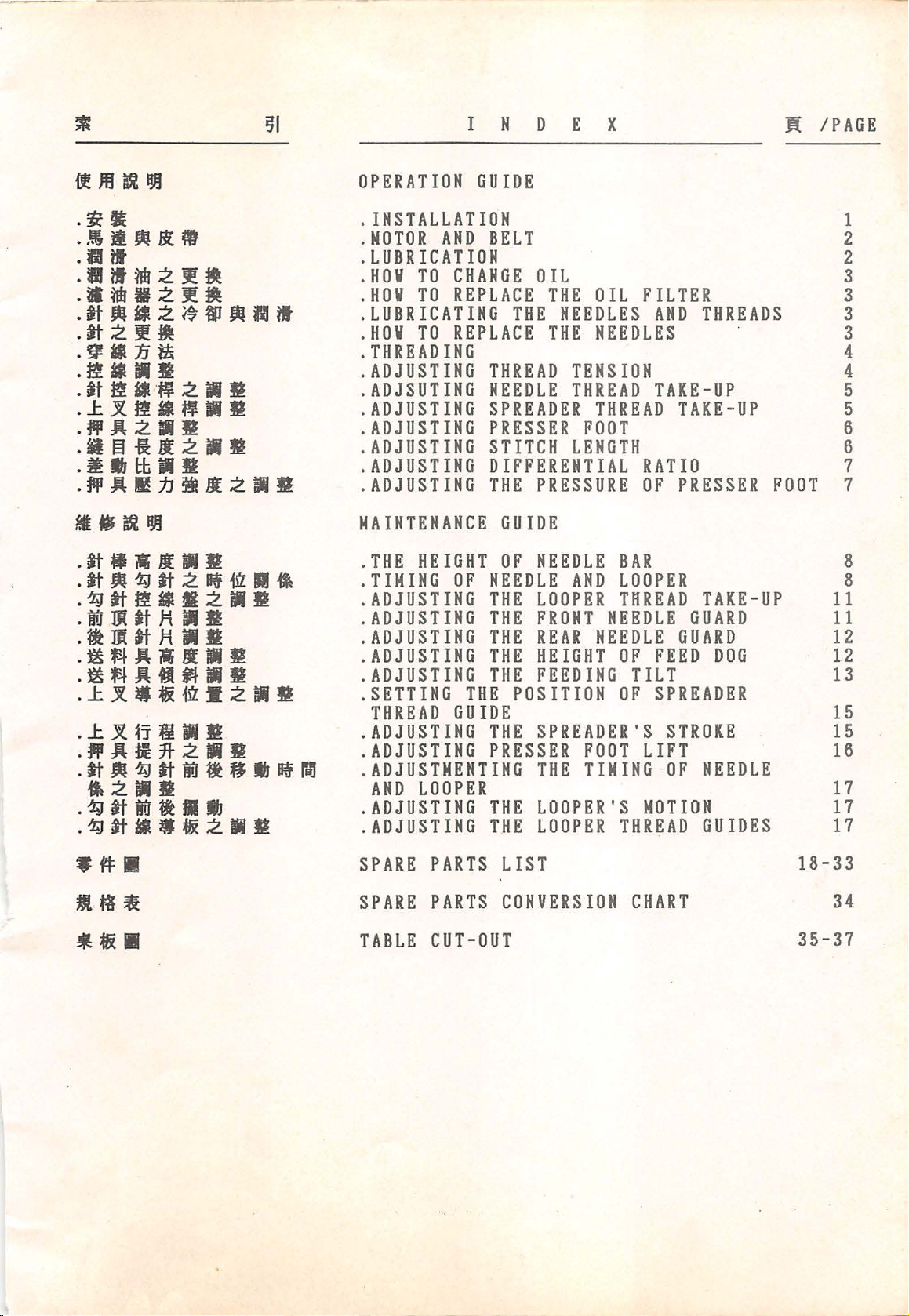
INSTALLATION
!.Before
refer
and
enclosed,
sequence
quake-proof
and
2.Be
direction
motor
pressed
20
fasten
3.Regarding
motor
refer
the
the
sure
mm.
to
installing
to
table
necessary
according
of
installation,
base,
cloth
that
is
belt
with
For
the
pulley
finger
safety
belt
machine
Table
machine,please
cut-out
attachment
thread
waste
the
clockwise,and
tension
diameter,
1.
chute.
motor
inward
reason,
cover.(Fig
speed
drawing,
to
can
the
to
fix
stand
turning
the
about
please
1,2)
and
please
as
be
2
·*
li
/!1./Jf
r3
Machine~
~~
6,000
5,500
5,000
4,500
4,000
50mm.
Fig
Motor
1
Table
Pulley
60HZ
105
95
85
80
70
1
(~
Outer
Remarks:
!.During
2.The
1)
Diameter
50HZ
125
115
105
95
85
the
shouldn't
speed
sure
of
motor
is
about
(mm)
Motor
Belt
~~N-,tg)
l)"
t
35"
~
34"
the
machine,
exceed
listed
to
choose
pulley.
standard
50mm.
first
month
the
thickness
in
the
maximum
80%
Table
correct
Fig
of
of
1.
of
2
using
speed
the
Make
size
table
- 1 -
Page 4
tcroR
~BELT
1
••
~.
'".
3*6
2.,15
i1
2fi
i2.
2.
1/2,'1
M.
tc
jJ
VI!Blfl•
&It:'
il
(gl
II.
400£
,\lti&:MtateJt:roaa.z·•-••
II
Bl
) ,
M
ft
..
Ill
!.Clutch
2.The
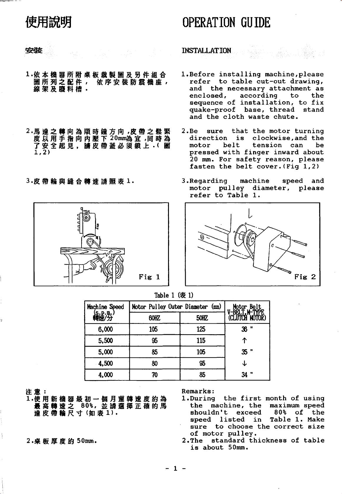
LUBRICATION
l.ftl.
JU
MOBIL#lO
!'2
ESS0#32!1fiU ifl
2.
iltlbll·
2.Eif
~
ii
8 U
1£
It
II
ftiJ
B If
Nl
••
tt
li
• •
1£
fJ!
m
tf1
~
it
it
.A
f1i
ll.t.l
~t~~~llttti.J\J:raaznaepiiJ.
(.
"A"Ifbllit.AfiiiJt:l
3,
4)
~-~··
,mJ
~
'"
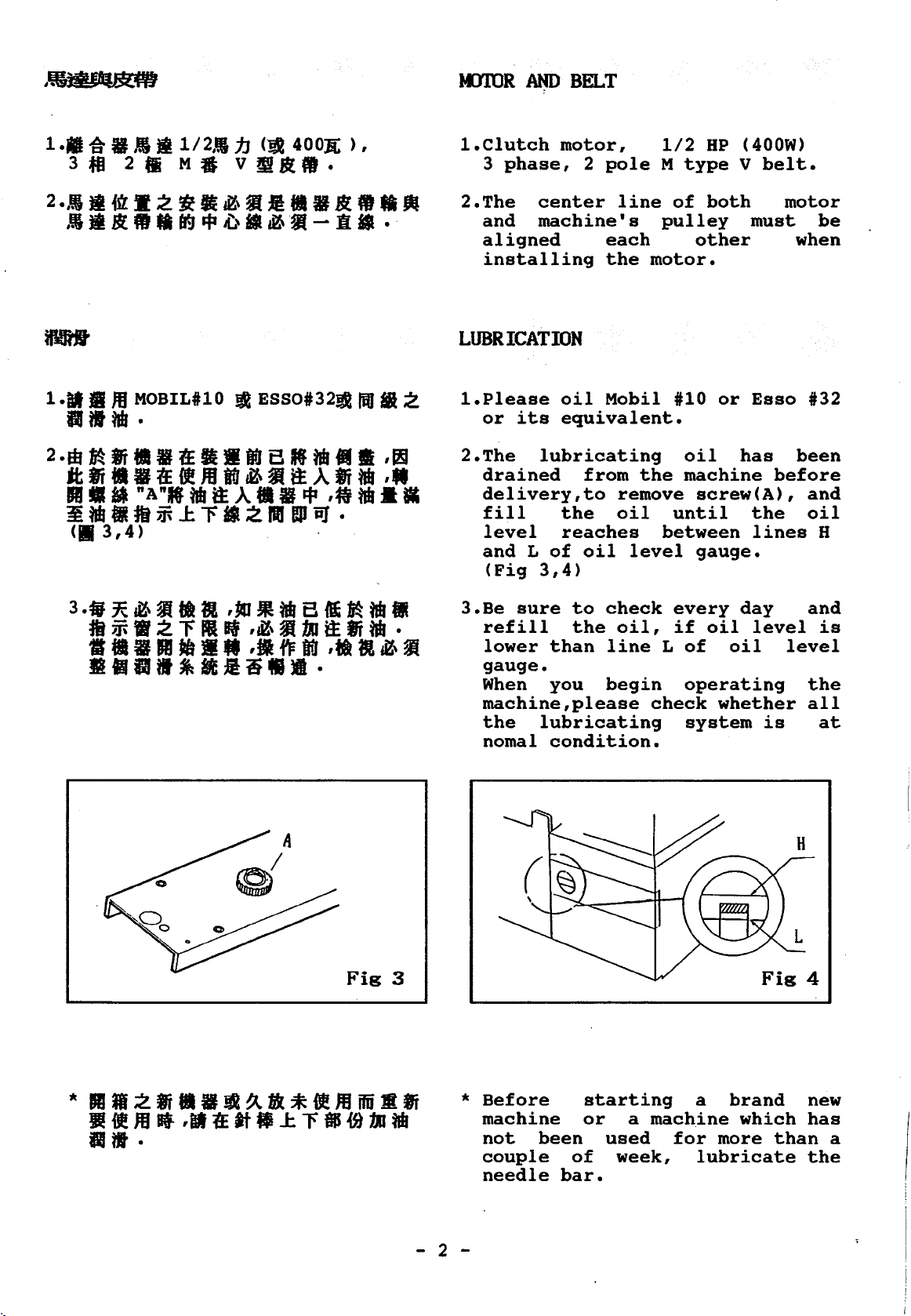
!.Please
2.The
motor,
3
phase,
center
and
aligned
installing
or
drained
delivery,to
fill
level
and L of
(Fig
machine's
oil
its
equivalent.
lubricating
the
reaches
3,4)
2
pole
each
the
Mobil
from
oil
1/2
M
line
remove
oil
of
pulley
motor.
the
until
between
level
HP
type
both
other
#10
or
oil
machine
screw(A),
gauge.
(400W)
V
belt.
motor
must
Esso
has
before
the
lines
be
when
#32
been
and
oil
H
Fig
3
3.Be
sure
refill
lower
gauge.
When
machine,please
the
noma!
than
you
lubricating
condition.
to
the
check
oil,
line
begin
every
if
L
of
operating
check
system
day
oil
level
oil
whether
is
Fig
and
is
level
the
all
at
4
*
Before
machine
not
couple
needle
- 2 -
been
bar.
starting
or
used
of
a
machine
week,
a
for
more
lubricate
brand
which
than
new
has
a
the
Page 5
HOW
1U
CHANGE
OIL
1.31.
M < 1
ltillliJitll
2 .a
g-ut*
II
M
ti
J! •
--~.
)Jill
,~
.(llf5)
~
M
a • a ilt ,ftl
li
tdl
I
Jll
It
2.
ti
~
Bn
&'3
• (lg ill
:ffi
~
~
~
j~
m w
_ij
J!
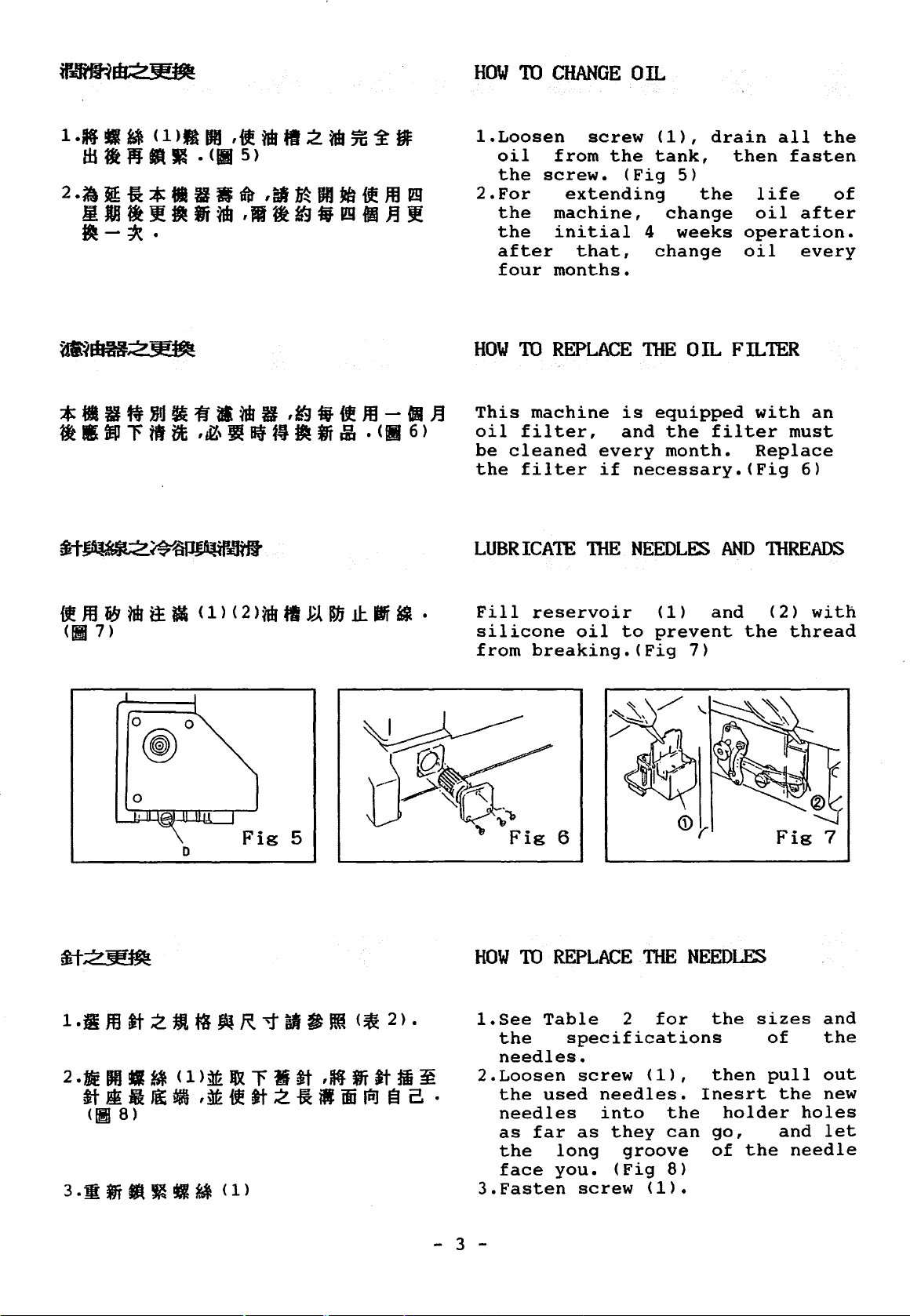
!.Loosen
oil
the
2.For
the
the
after
four
HOW
This
oil
be
the
from
screw.
extending
machine,
initial
months.
TO
REPLACE
machine
filter,
cleaned
filter
LUBRICATE
screw
that,
every
if
'mE
the
(Fig
(1),
tank,
4
change
drain
5)
the
change
weeks
TilE 0 IL FILTER
is
equipped
and
the
filter
month.
necessary.(Fig
NEEDL~
AND
all
then
fasten
life
oil
after
operation.
oil
every
with
must
Replace
6)
111READS
the
of
an
D
Fill
silicone
from
HOW
!.See
2.Loosen
3.Fasten
reservoir
breaking.(Fig
1U
the
needles.
the
needles
as
far
the
face
oil
to
REPLACE
Table
specifications
used
long
you.
screw
needles.
into
as
they
(Fig
screw
2
groove
(1)
prevent
niE
for
(1),
the
can
8)
<1>.
and
the
7)
NEEDLES
the
sizes
then
Inesrt
holder
go,
of
the
<2>
thread
Fig
of
pull
the
and
needle
with
7
and
the
out
new
holes
let
- 3 -
Page 6
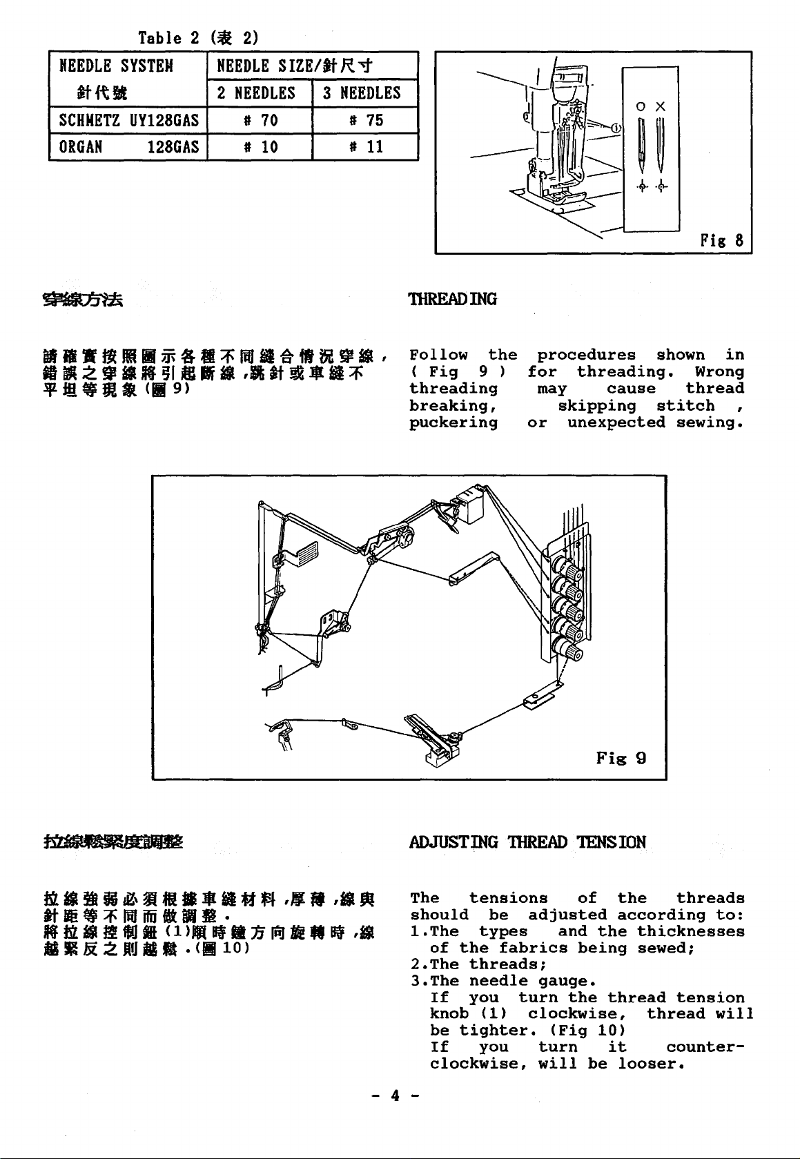
Table 2
(~
2)
NEEDLE
SYSTEM
at{t!J!
SCHNETZ
UY128GAS
ORGAN
128GAS
NEEDLE
2
NEEDLES 3 NEEDLES
I
70
I
10
SIZE/at
R.
# 75
#
'1'
11
niREADING
Follow
(
Fig
threading
breaking,
puckering
the
9 )
procedures
for
or
threading.
may
skipping
unexpected
cause
shown
Wrong
thread
stitch
sewing.
Fig 8
in
,
ADJUSTING
-
The
should
1.The
2.The
3.The
- 4 -
tensions
be
types
of
the
fabrics
threads;
needle
If
you
knob
be
If
clockwise,
(1)
tighter.
you
TIIREAD
adjusted
and
gauge.
turn
clockwise,
(Fig
turn
will
1ENS
of
being
the
be
Fig
9
ION
the
according
the
thicknesses
sewed;
thread
10)
it
looser.
threads
tension
thread
counter-
to:
will
Page 7
ADJUSTING.
NEEDLE
~-
TAKE-UP
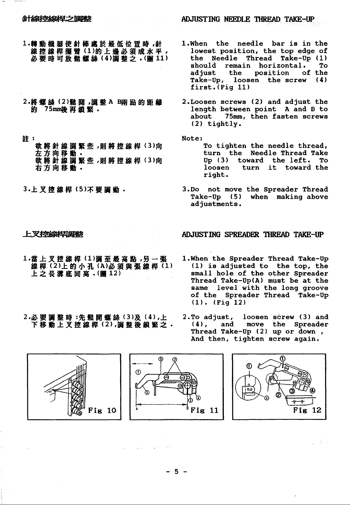
1.When
lowest
the
should
adjust
Take-Up,
first.(Fig
2.Loosen
length
about
(2)
tightly.
Note:
To
turn
Up
loosen
right.
3.Do
not
Take-Up
adjustments.
the
position,
Needle
remain
the
screws
between
75mm,
tighten
the
(3)
move
(5)
needle
Thread
loosen
11)
(2)
then
the
Needle
toward
turn
the
when
bar
the
top
Take-Up
horizontal.
position
the
and
point
fasten
needle
Thread
the
it
Spreader
.making
is
in
edge
of
screw
adjust
A
and B to
screws
thread,
left.
toward
Thread
the
of
(1)
To
the
(4)
the
Take
To
the
above
ADJUSTING
1.When
(1)
small
Thread·
same
of
(1).
2.To
(4),
Thread
And
the
is
hole
level
the
(Fig
adjust,
then,
SPREADER
Spreader
adjusted
of
the
Take-Up(A)
with
Spreader
12)
loosen
and
Take-Up
move
(2)
tighten
niREAD
Thread
to
the
other
must
the
Thread
screw
the
up
screw
TAKE-UP
top,
Spreader
be
long
Spreader
or
again.
Take-Up
the
at
the
groove
Take-Up
(3)
and
down ,
Fig
10
Fig
- 5 -
11
Page 8
ADJUSTING
PRESSER
FOOT
B
~
~at
-Jt
dJ
6-18ft
1 •
2£
•
4 •
OIDinfll
IV
II
i'! •
!I
ll
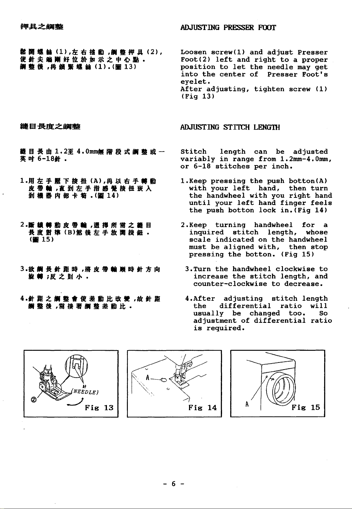
Loosen
Foot(2)
position
into
eyelet.
After
(Fig
ADJUSTING
-
Stitch
variably
or
!.Keep
with
the
until
the
2.Keep
inquired
scale
must
pressing
screw(!)
the
adjusting,
13)
6-18
pressing
your
handwheel
push
be
and
left
to
let
center
and
right
the
of
tighten
STITCH LENGnl
length
in
range
stitches
left
your
botton
turning
stitch
indicated
aligned
the
the
with
left
botton.
can
from
per
hand,
hand
lock
handwheel
on
with,
adjust
needle
Presser
be
inch.
push
you
length,
the
Presser
to
a
may
screw
adjusted
1.2mm-4.0mm,
botton(A)
then
right
finger
in.(Fig
handwheel
then
(Fig
proper
get
Foot's
(1)
turn
hand
feels
14)
for
whose
stop
15)
a
3 .a •
-a
• • ; li. z
tt
m
Bf
ld
NEEDLE)
J
,JI * • • •
,.~
•
It
Fig
13
If
tt
1i
lfiJ
3.Turn
increase
counter-clockwise
4.After
the
usually
adjustment
is
Fig
the
handwheel
the
adjusting
differential
be
required.
14
stitch
changed
of
differential
clockwise
length,
to
decrease.
stitch
ratio
too.
to
and
length
will
So
ratio
- 6 -
Page 9
*••zmiJtbiiJfl
1:2.9
* •• i11J
••••
tb • ((1116)
1:0.3
••~
<1>,J:rt¥1JJIMt¥
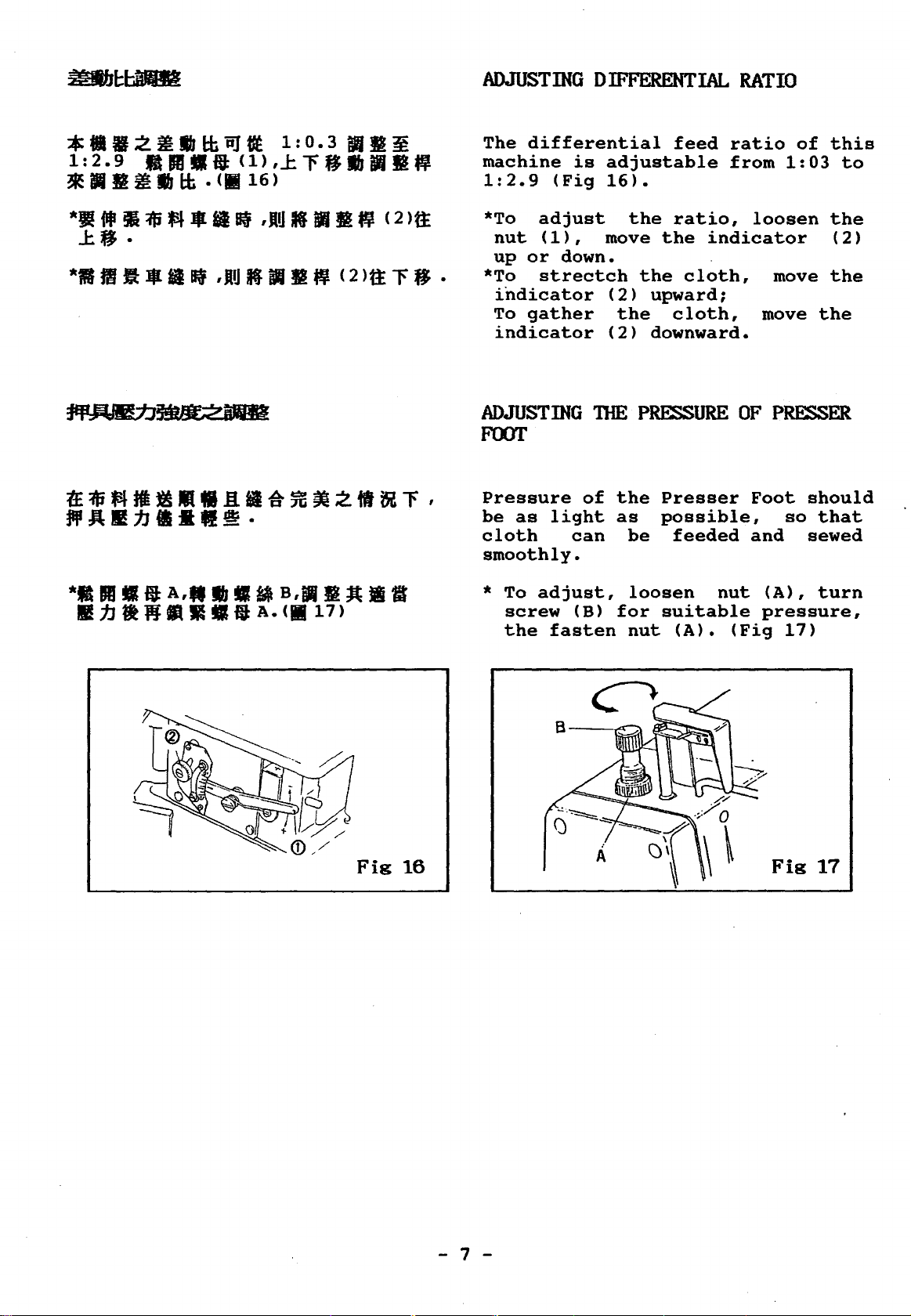
ADJUSTING
The
differential
machine
1:2.9
is
(Fig
DIFFERENTIAL
feed
adjustable
16).
RATIO
ratio
from
of
1:03
this
to
*J!
J:f¥.
*II
fi1Jii
m
Jllllll
:$
ft
lll
Sf
iii
Sf
,JlU
,JlU
If
K Jl II
B1
t¥
M
< 2
'-it
>tt
< 2
r
>tt
fJ
*To
nut
up
*To
•
indicator
To
indicator
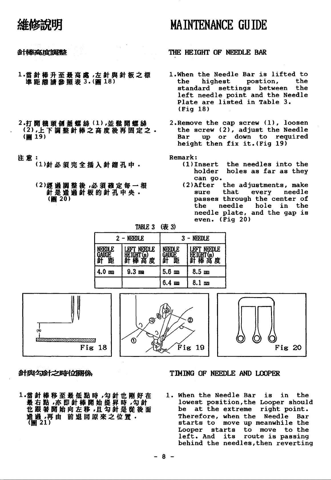
ADJUSTING
FOOT
Pressure
be
cloth
smoothly.
*To
adjust
(1),
or
strectch
gather
as
adjust,
screw
the
down.
Tim
of
light
can
(B)
fasten
the
move
the
(2)
the
(2)
P~URE
the
as
be
loosen
for
nut
ratio,
the
indicator
cloth,
upward;
cloth,
downward.
Presser
possible,
feeded
nut
suitable
(A).
(Fig
loosen
move
move
OF
P~ER
Foot
and
(A),
pressure,
17)
should
so
sewed
the
(2)
the
the
that
turn
Fig
16
- 7 -
Fig
17
Page 10
MAINTENANCE
niE
HEIGHT
OF
GUIDE
NEEDLE
BAR
2-
NEEDLE
TABLE
3 (¥i
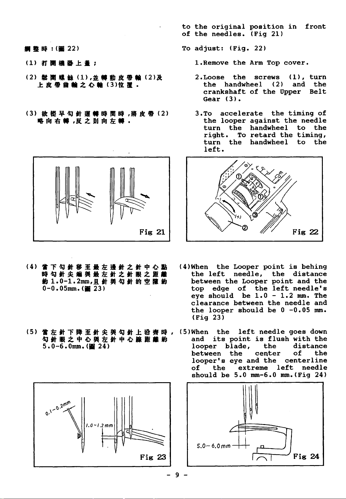
1.When
the
standard
left
Plate
(Fig
2.Remove
the
screw
Bar
height
Remark:
(1)Insert
holder
can
(2)After
sure
passes
the
needle
even.
3)
3
-NEEDLE
the
Needle
highest
needle
are
18)
the
up
then
go.
settings
point
listed
cap
screw
(2),
or
needle
(Fig
adjust
down
fix
the
holes
the
adjustments,
that
through
plate,
20)
Bar
is
postion,
between
and
in
Table
to
it.(Fig
needles
as
every
the
hole
and
lifted
the
(1),
the
far
center
the
the
the
Needle
3.
loosen
Needle
required
19)
into
as
they
make
needle
in
gap
the
the
to
of
is
(a)
J,////ff@'///M////$///////4
Fig
NEEDLE
GAUGE
atm
4.0
mm
18
ftrT.
9.3
BBI
NEEDLE
GAUGE
atm
5.6
mm
6.4
IDIIl
TIMING.
1.
When
lowest
be
Therefore,
starts
Looper
left.
behind
ftr1::
8.5
mm
8.1
mm
OF
NEEDLE
the
Needle
position,the
at
the
extreme
when
to
move
starts
And
its
the
needles,then
AND
Bar
the
up
to
route
Fig
LOOPER
is
in
Looper
right
Needle
meanwhile
move
point.
to
is
passing
reverting
20
the
should
Bar
the
the
- 8 -
Page 11
••
Elf
:
<•
22)
to
of
To
the
original
the
needles.
adjust:
(Fig.
position
(Fig
21)
22)
in
front
(1)1J···J:.·;
<2>
ltiiJ•ta
J:lll•••z..r.
<1>,tt.IJI1l.M
...
(3)ftll.
<2>A
Fig
21
1.Remove
2.Loose
the
crankshaft
Gear
3.To
the
turn
right.
turn
left.
accelerate
looper
the
Arm
the
handwheel
(3).
the
the
screws
of
against
handwheel
To
retard
handwheel
Top
the
(2)
the
cover.
(1),
and
Upper
timing
the
the
Fig
turn
the
Belt
needle
to
the
timing,
to
the
22
of
1.0
-I.Z
mm
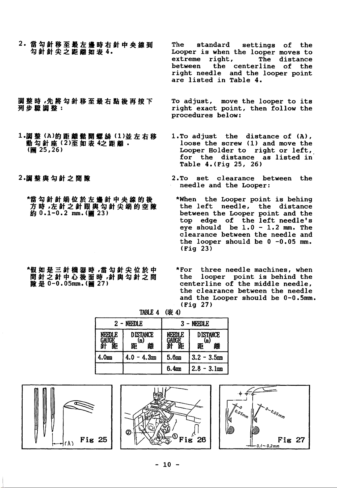
(4)When
the
between
top
eye
clearance
the
(Fig
(5)When
and
looper
between
looper's
of
should
the
left
the
edge
should
looper
23)
the
its
blade,
the
be
Looper
needle,
Looper
of
be
between
should
left
point
the
eye
and
extreme
5.0
point
the
point
the
1.0
mm-6.0
left
the
be 0 -0.05
needle
is
flush
the
center
the
is
distance
and
needle's
1.2
mm.
needle
goes
with
distance
of
centerline
left
mm.(Fig
behing
the
The
and
mm.
down
the
the
needle
24)
S.0-6.0mm~
Fig
23
- 9 -
Fig
24
Page 12
The
Looper
extreme
between
right
are
To
right
procedures
standard
is
needle
listed
adjust,
exact
when
right,
the
in
move
point,
below:
settings
the
looper
centerline
and
the
Table
the
then
The
looper
4.
looper
of
moves
distance
of
to
follow
the
to
the
point
its
the
TABLE
4
1.To
2.To
(¥&
*When
*For
4)
adjust
loose
Looper
for
Table
needle
the
between
top
eye
clearance
the
(Fig
the
centerline
the
and
(Fig
the
the
4.(Fig
set
the
left
edge
should
looper
23)
three
looper
clearance
the
27)
the
screw
Holder
distance
clearance
and
the
Looper
needle,
the
of
between
should
needle
of
Looper
distance
(1)
to
25,
Looper:
Looper
the
be
1.0
point
the
between
should
and
right
as
26)
between
point
the
point
left
-
1.2
the
needle
be
0
machines,
is
behind
middle
the
be
of
move
or
left,
listed
is
behing
distance
and
needle's
mm.
-0.05
needle,
needle
0-0.5mm.
(A),
the
in·
the
the
The
and
mm.
when
the
2
rA)
Fig
NEEDLE
GAUGE
ltfti
4.0mm
25
-NEEDLE
DIST~
Be(a
8
4.0 -4.3mm
-
10
3-
NEEDLE
ifUGjg
5.6mm
6.4mm
-
NEEDLE
~~~
3.2 -3.5mm
2.8 -3.1mm
O:I-0.2mm
Fig
27
Page 13

-~---------
----------
2/3
ADJUSTING
The
Looper
release
when
is
!.For
2.For
To
in
the
2/3
(Fig
of
to
the
(Fig.
adjust:
the
the
the
end
position
28)
the
the
29)
LOOPER
the
thread
point
following
2-needle
of
the
3-needle
left
lower
loosen
then
Thread
niREAD
Thread
of
the
left
of
the
machine,the
needle
edge
the
turn
Cam
TAKE-UP
Cam
of
the
left
position:
machine,
needle
Looper.
is
vertical
of
the
screw
the
(2).(Fig
should
Looper
needle
while
is
in
end
Looper.
(1),
Looper
30)
Fig
28
Fig
29
ADJUSTING
!.When
the
right
.· . exact
the
needles
Needle
of
the
2.The
needles
Guard
that
pass
3.To
and
(1)
only
through.
adjust,
move
back
THE
FRONT
Looper
..
exact_
_point
:point·,.
Guard
needles.(Fig
clearance
and
the
should
the
needle
loosen
the
Front
or
forth.
NEEDLE
goes
to
it:
..
passes
and
(1)
the
is
31)
between
Front
rema~n
threads
the
Needle
30
GUARD
from
the
the
left
behind
Front
in
front
the
Needle
so
close
can
screw(2),
Guard
-
11-
Page 14

ADJUSTING.!
THE
REAR
NEEDLE
GUARD
1.8
1
«f
iJ
~II
0-0.5MM,If
(1),~JifJf.ltllblltt.f*Ji
(.
33)
fJIJit.l
(2).
M
When
the
of
clearance
the
needle.
clearance
middle
point
in
the
1.In
2.When
the
right
the
looper
the
middle
order
about
screw
guard
top
line
located
the
right
needle
of
And
of
needle
when
rear
0
(1),
(2)
the
of
its
(A)
looper
needle,
guard
about
point
it
is
0 - 0.5mm
and
the
needle.(Fig
to
back
needle
of
1/3
needle
looper
of
the
gain
0.05mm,
then
or
lowest
the
be
point
the
0-0.5mm
and
move
forth.(Fig33)
is
needle
low
eye.(Fig.
is
centerline
should
between
the
also
centerline
position,
the
between
the
point
32)
a
clearance
loosen
the
in
below
guard
the
behind
have
right
same
the
looper
is
of
the
needle
the
the
is
top
of
34)
a
••.
If
8
rt~IJJ.
·+·¥'~
r·--"
r
1.3:
MM.
r
,,
'J.'rlo
A
i5
:tfi
a J:
<II
·.,
35)
II
tJ M < 1 >
....
O.os
0.1-0.2mm
11-
"''~~
Fig
I M
,~
nt
32
i8i
ft
tt » < 2
II
It
0.8-1.2
>iaJ
.1:
*To
ADJUSTING
1.The
.
adjust,
then
upwards
is
0.8
highest
move
or
THE
height
position.
loosen
the
Rear
downwards.
HEIGHT
of
1.2mm
when
the
Needle
OF
Main
it
(Fig
screw
Fig
FEED
Feed
is
35)
(1)
Guard
34
DOG
dog
in
the
-
2.Adjust
12
-
so
same
of
that
the
the
level
Main
Differential
the
point
height
Feed
Dog.
as
B
the
Feed
is
point
at
Dog
the
A
Page 15

ill
~
Mlf
t1
•
Mil.
<II
36
>
tat
< 4 > < 5 >
,~
J:
r fJ
Fig
1J
35
~
To
adjust,
(4)(5),
upwards
loosen
and
or
move
downwards.
the
the
feed
(Fig
screws
dog
36)
••
Iff:
l.IIJ-r••
<II
37>
(l)&_J:ii
(2)(3).
ADJUSTING
The
the
parallel
when
highest
To
!.Remove
2.Loosen
straight
whole
the
Feed
position.
adjust:
cover ( 2) ( 3)
the
feeding
screw·
niE
feed
with
(Fig
the
the
tilt.
FEEDING
line
dog
tooth
the
Dog
is
37)
screws
•
screw
(5)
to
TR.T
(a),
Needle
raised
(1)
(4)
adjust
crossing
tips,
Plate
to
the
and
the
and
turn
the··
is
-
13
SE1TING
l.The
be
the
Plate.(Fig
-
11IE
height
kept
top·
Fig
:g
POSITION
at
surface
OF
of
the
Spreader
ar.ound 8 •.
of
38)
SPREADER
3-8.
7mm
the
Needle
must
from.
Page 16

Blfillf:
2.There
between
point
the
needle.
clearance
the
left
in
(Fig
To
adjust:
is
and
Spreader
hooking
needle
its
extreme
39,40)
a
clearance
the
Spareader's
the
about
point
when
left
passes
And
4.5-5.mm
left
the
about
needle
there
(B)
Spreader
point.
hooking
the
between
and
0.5mm
when
left
is
a
the
is
Cl>.f&lltl~
UfJ
It
tJ
!tl
t;
( 2 ) •1:
;tj
tJ
~8.5MM,~filtll!tiM
C4>,MIJJ:Jl.filt¥
IJ
(
1)
,~fill~~.
C
4)
• Cfl •
JJJ
1:
J(
41)
( 1 ) I
I! ~ ,.
r-
~
~6.1mrn
W~/M
.\.
A
at
C3>.
I\
I
Fig38
<5>,&
,
••
fi
;2
~
!.Loosen
move
forth,
Spreader
finishing
the
2.Move
downwards
the
fasten
the
the
screw
the
needle
the
screws
Spreader
while
Lever
the
(4).
spreader
to
set
plate
screw
turning
(5),
setting,
(Fig.41)
(1)
its
to
8.5mm ,
(3).
(4)
,
(1)
back
tighten
upwards
height
Fig
and
or
the
after
or
from
then
39
Fig
8.3-B.7mm
40
-
14
-
Fig
41
Page 17

SE'ITING
'DIREAD
11IE
GUIDE
f(EITION
OF
SPREADER
l.When
lowest
(2)
eye
clearance
and
set
2.When
lowest
should
Spreader
Needle
concavity
the
other.
,--·
••
.#"
__
_
__,
the
position,the
should
of
the
the
to
the
position,
Thread
thread
(Fig
)
Needle
be
set
guide
between
Spreader
O.Smm.
Needle
be
l.Omm
Thread
Guide
of
the
eye
42)
Bar
Thread
just
(3).
Thread
(1)
(Fig
Bar
42)
moves
the
between
Guide(2)
(3).
Spreader
should
is
in
Guide
below
And
Guide(2)
should
to
its
clearance
the
and
the
The
and
face
each
its
the
the
be
.(.
8.3-
B.7mm
~/
ADJUSTING
The
Spreader's
(Fig
!.Remove
2.Loosen
39)
screw
(1).
Connecting
downwards.
*In
order
Spreader's
Connecting
Fis
niE
the
the
42
SPREADER
stroke
Arm
(Fig
nut
Rod
stroke,
Rod
Cover
43)
(2)
(3)
to
(3)
.STROKE
is
17-17.5mm
and
and
move
upwards
decrease
move
upwards.
the
the
or
the
the
*In
order
Spreader's
Connecting
-
15
-
to
stroke,
Rod
(3)
increase
move
downwards.
the
the
Page 18

3
••••
,JIJ:ll
......
3.After
fasten
adjustments,
the
above
Fig
43
said
remember
screws.
to
2.••••
<l>,~•••aa
4.tW.fli!PJ:fl-tJM
~112i1M
<1>.
<2>rtrt.
<2>ffllflJift
<3>,
ADJUSTING
Presser
distance
and
Presser
position.
!.Rotate
2.Loose
3.Lower
4.After
the
the
position;
screw
Presser
height
screw
(3)
lock
Feed
the
the
and
the
(.2);
(2)
P~ER
Foot
between
Needle
Foot
(Fig
the
adjustments,
is
44)
handwheel
Dogs
nut
lever(3)
Foot
up
to
tighten
position.
FOOT
Lift
the
Plate
at
to
(1)
to
touch
LIFi'
Presser
its
the
and
and
the
the
means
when
highest
to
lower
raise
raise
the
nut
the
Foot
the
lower
lowest
the
the
proper
the
lever
(1)
to
-
16
-
Fig
44
Page 19

ADJUSTING
NEEDLE
MOVEMENT
AND
niE
niE
OF
LOOPER
TIMING
BACK
BETWEEN·
AND
FORni
11m
Loosen
the
of
the
ADJUSTING
1.The
behind
left
orginal
the
2.The
according
needle,
(4),
clockwise
looper's
contrary,
counter-clockwise
the
the
eccentric
crankshaft
11m
Looper's
the
end,
position
needles.
adjustment
by
turn
motion.
screw
LOOPER
needles
then
to
loosening
to
motion.
turn
(Fig
(1),
(2)
and
(3).(Fig
'S
motion
reverts
in
can
the
the
decrease
45)
and
the
t«JTION
is
to
front
be
size
the
screw
On
the
to
increase
align
groove
45)
passes
the
to
done,
of
screw
screw
far
the
of
the
(5)
the
the
ADJUSTING
When
exact
between
slightly
According
the
Thread
level
thread
the
point,
bracket
Guides
which
guides
11m
LOOPER
Looper
the
the
tensioned
to
two
the
(3),
the
are
is
looper
guides
(Fig.
alinging
adjust
(3)
and
eyes
parallel.
1liREAD
at
the
should
46)
(4)
of
GUID~
left
thread
be
mark
the
the
to
on
two
the
two
Fig
45
-
17
-
Fig
46
Page 20

PARTS LIST FOR MA GROUP
MA04D
_...........SM132
K 7
MA02D
'
~
MA1:.:3
SM461
-
18
-
MAll-2
MAll-1
MAOl
MAll
SM
432
Page 21

/
/
/
/
Page 22

MCB:'f
SM433-9T
MBOl
SM446
SM436
,v
I
0
SM496
MB04
MB05
WMBOO
-
20
-
Page 23

~502
I
- 21 -
Page 24

HC/2
r
MC/3
-
22
-
Page 25

f1010
SHS02
HD~
MDII
\
604
r
PM/II
HD/7
(MDJ!-2
r8ody\
1/
l,·
MD31-I S/1602
CBeot;ng)
-
23
-
Page 26

st.'•
~04
--~~HE/6
MH7~
...
,
V'f£85
4~
I I
SK441
1
SK27D
""
'~
""'ME14 \
M£11
SH/38
ME28
tb
91135
SM~
431
~~
/~
HEB2
/
HE71
r-tb4
·-;._,.
~1'1401
-~,
sMSIO
Page 27

MFOI-1
SM502
~
\
\
MF30
-
25
-
SMS34
HFV
Page 28

4
SM430
HG56
-
26
-
Page 29

MV24
EN0601
~14D
. . -MH78
~
~
~137
SMSII
MH41
-
27
-
Page 30

MJt/5
SK-2/6
-
28
Pxxxx
-
Page 31

S/1432
'\ri
WN400
v~K~
-
29
-
HKI'l
-~
r
SN301
~,K21
Page 32

SM461
/
K2q
MK28
SM482
G..'-,
11K23
-
30
-
Page 33

------
-----
··----
ML13
NH4.10
SM43~
~
'
HLSQ
-
31
-
HL/7
A'Jr.
tf'MLJ9
SN430
Page 34

1(
KXOS
KX04
i.i
~;.-··-"forf7-
FR
··au
L
YT
-·------·
--·---
----·
KX/0
-···-
--·
··--
-
32
-
Page 35

PARTS LIST
FOR
MY
GROUP
MY14
MYOl
KY05
...............
MY02
KY0
7
I
I
KYOB
https://manualmachine.com/
,K\Oq
~
Ky04
--KY21-
(FOR FR
KY2
KR3
l
1
5
ONLY)
-
33
K T
14
-
Page 36

SPARE
PARTS
OONVERSION
CHART
MODEL
F007-V122
F007-U122
F007-U122
/FP
F007-V123
F007-V222
/FQ
F007-U222
/FQ
GAUGE
240
248
3S6
364
240
248
3S6
364
232
240
248
3S6
364
240
248
356
364
240
248
356
364
NEEDLE
HOLDER
M4240
M4248
M4356
M4364
M4240
M4248
M4356
M4364
M4232
M4240
M4248
M4356
M4364
M4240
M4248
M4356
M4364
M4240
M4248
M4356
M4364
NEEDLE
PLATE
E1524
E1S25
E1826
E1827
E1524
E1S2S
E1826
E1827
E1623
E1534
E153S
E1836
E1837
E3024
E302S
E3326
E3327
E3024
E3025
E3326
E3327
MAIN
FEED
D1206
D1206
D1207
D1207
01206
D1206
D1207
D1207
D1206
D1206
D1206
D1207
01207
D121S
D121S
D1216
D1216
D1215
D121S
D1216
D1216
DOG
DIFF.
FEED
DOG
812S8
812S8
812S9
812S9
81258
812S8
81259
812S9
812S7
81258
81258
81259
812S9
81261
81261
81262
81262
81261
81261
81262
81262
PRESSER
FOOT
P0014
POOlS
P0116
P0117
P0214
P021S
P0316
P0317
P4011
P0014
POOlS
P0116
P0117
P1814
P181S
P2116
P2117
P2314
P231S
P2616
P2617
SPREADER
MH41
----
----
MH41
MH41
----
NEEDLE
UY128GAS
110
110
Ill
Ill
110
110
Ill
Ill
114
110
110
Ill
Ill
110
110
Ill
Ill
110
110
Ill
Ill
F007-V223
F007-VS22
/FE(FFC)
/FR
F007-US22
/FE(FFC)
/FR
F007-VS22
/FE
/FFC
F007-US22
/FE
/FFC
F007-U612
/FBQ
240
3S6
364
240
248
356
364
240
248
356
364
240
248
356
364
240
248
356
364
2S6
264
M4240
M4356
M4364
M4240
M4248
M4356
M4364
M4240
M4248
M43S6
M4364
M4240
M4248
M4356
M4364
M4240
M4248
M4356
M4364
M4356
M4364
E3034
E3336
E3337
E6024
E602S
E6326
E6327
E6024
E602S
E6326
E6327
E1S24
E152S
E1826
·E1827
E1S24
E1S2S
E1826
E1827
E1826
E4001
E1827
E4001
D121S
D1216
D1216
02221
D2221
D2222
D2222
D2221
D2221
D2222
D2222
D1206
01206
D1207
D1207
01206
01206
D1207
D1207
D5001
D5001
81261
81262
81262
82267
82267
82268
82268
82267
82267
82268
82268
812S8
81258
812S9
812S9
812S8
81258
812S9
81259
85001
85001
P1814
P2116
P2117
P2814
P281S
P3116
P3117
P3314
P331S
P3616
P3617
P2914
P2915
P3216
P3217
P3414
P341S
P3716
P3717
P4000
P4002
P4001
P4002
N841
M841
----
MH41
----
----
----
110
Ill
Ill
110
110
Ill
Ill
110
110
Ill
Ill
110
110
Ill
Ill
110
110
Ill
Ill
114
(116)
114
(116)
F007-U612
/FBP
256
264
M4356
M4364
E1826
E1827
-
D1207
D1207
34
812S9
81259
-
P4000
P4001
----
----
114
116
Page 37

TABLE
=~tSJZ.Jfll'~:&t-t&IM
TABLE
~.fil:
UNIT:
NO.
CUT-OUT
M M
MM
F007
SEMI-SUBMERGED
0 N
o o
.q-
r"J
L() L()
co..q-
N N
0
¢17
15
8-B
B-B SECfiON
HIJ
fm
445--
345--1--
310
119
~-
0
------
,---3
-~:-f/J-9--,
---~
~
t
7-RlO
...___---;---------:-+-----··-
__
J:_~
J
____
___:15_9_.
1¢30
R23
234
4_-~13~---;------L----
-~~---~--.IL~--.--
540
465
H--:r7f---
-~
412
392
383
B
----!--
.
..
- - . -
55
0
("....
L()
l.()
0
0
r")
0
--
N
0
Page 38

TABLE
NO.
F007-1
=~.SJL.$""l'~~*t&IIB
TABLE
ft!{\1::
UNIT:
CUT-OUT
MM
MM
SEMI-SUBMERGED
445
--r---
345
--t----
310-+--
15
B-B
B-B
HIJ
oo
SECTION
119
--t---
.---,
1-----------------:----~-----7"------y-
3-~¢9
~
~ 1 -_l__~
I
I I
7-RlO
I
R23
234
159
1¢30
~-
I
I B
I
0
---t-"""
-===::t=.
¢17
540
465
412
3 9 2
383
60
---.1~---
0-----
0
<D
LC>
4-~13~-
--+---__.____
0
0
t'")
---t-
0
0
55
0
Page 39

TABLE
=
jf
.sp.
TABLE
NO.
•
I'
F007-2
~
CUT-OUT
:it
. *
*&
llil
SEMI-SUBMERGED
l.C)
r---.
0
!t!-lll:
UNIT:
MM
MM
8-8
B-B
SECTION
15
HIJ
iii
445
---
345--f---
310
--1--
119
--~--
60
--1---
0------
I
1.
l i 0
r---.
L()
Ln
l.()
N
l.()
I
0
0
n
0
_)
0
Page 40

IN
S. NO. 05-FS
01
MAR. 19
93
•
suBJE
CT TO C
HAN
GE
WITHOUT
NOTICE.
 Loading...