

Page 1
DL7200
1f ffl
~
a~
~
INSTRUCTION BOOK
OL1200-aa11
(€
f/41
~
$
iAi~Jliif.l~~OEJ
KAULIN
MFG.CO
..
LTD.
Page 2

*
ii
ffl
ii~•~
3
ii
ffl
nt
.I-~
""FM~
:
The
DL7200-BM1-XX/DL7200-BH1-XX
~.
Explanation of Dangerous Level
content
*.
~
A
fe:llt
Dangerous
of
this instruction book
ffl
~
!4l
~
m.iffl.
11:t~
!a
ffii
ii
fi
7 H ~
~
ffl"
.=.
~
J...
ff
ffl:
11
a2
~
t:
Don't ignore the warning sign and
Or
it
will cause the person or the third party seriously injured or dead
during maintenance.
M
~~mi
11:~
•
ac
mn.w-rr
7
~a2m=~J...fl~~~~•a•a•
A
51~ the person involved
Caut ion
Ignoring this warning sign and proceed incorrect operation will cause
or
dur
damaged
ing maintenance.
ir.J
ii~
a<J
the th i
is
for
the
models:
ti
tJUI
11c,
1i
II
lfi
~
)E
*
i3
I ffi
don'
t proceed incorrect operation.
a f4i11f,
rd
party wounded and equipment
-1i
• lfj
lriD"
~
•
;,
1
~
•
iffl
• •
=If
■
iS"lll~fi;J\&fi;J\8~~ml~
Explanation of Warning Signs and Labels
illbg5'fir,
Moving part, beware
~~I
il!JI~
of
L8
~■
!~'fit
ii
IJ1j
J\lliil
~i5-II~~~
Warning Si
gn
A
High voltage, beware of electric shock
i1l
51
R~
uL
, ~ lttHi 1' $
High temperature, beware of burns
•
A
it
(S)
ffi~tt•
Instruction Label
@
l.t Prohibited
tti!da<JIUI~~
Indication
of
ground wiring
industrial accident
~
Ml:
Page 3
I
I
1----------------------------------
! •sl INDEX
----------------------------------
------------------
ft/PAGE
~-----------------------------------------------------------------------------------------------:
--~~$1'iN~
GENERAL SAFETY INSTRUCTIONS
1
•li:£½•:iji~~
ffi~tl$Jl
lltt~½IIN
Mil
-~•jjjtsa<J~il'fiiii
~iHt~tili
fflt&
-~*ffllaTI•~~½
>i11$Ti
IMPORTANT SAFETY INSTRUCTIONS
WARNING
WARNING
SAFETY ILLUSTRATION OF NEEDLE GUARD
MOVING THE SEWING MACHINE
THE INSTALLATION POSITION OF THE SEWING
MACHINE
NAMES OF MAJOR
SPECIFICATIONS
IMPORTANT SAFETY INSTRUCTIONS OF THIS
MACHINE
TAG
PAR
TS
3
7
7
8
9
9
10
11
14
~ti
)djll~~
ti!'.19~&
ftrz~•
-~~~
SlliahHlr~MftZ~K
tlffl!1.
atlePJUI
ll~~AmTt-Bz~~
INSTALLATION
OIL
PAN
INSTALLATION
INSTALLING THE NEEDLE
SETTING THE BOBBIN
THREAD
THE
MOUNTING
THREADING THE MACHINE
ST
ITCH LENGTH ADJUSTMENT
ADJUSTMENT OF KNEE-CONTROL PRESSER
FOOT
STAND
BELT
COVER AND THE BOBBIN WINDER 20
LI
FTER
ASSEMBLY 20
15
16
17
18
21
21
22
LE
NEED
ADJUSTMENT
THREAD/BOBBIN THREAD TENSION
23
Page 4
,----------------------------------------------------------------------------------------------- ~
t I
:
I I
------------------------
•sl
f.,
tt-m:•
sni
-
------------
INDEX J
GENERAL SAFETY
INSTRUCTIONS
~-----------------------------------------------------------------------------------------------~
.ti:.
-g
'
Warning!
-~fflM~~-'~*~~ffi~-ffi~~ When
~.~~ff*~·••-~~~A~~~
.II.~ 0
ff~~m~~-Z~
.EL~
1.
ii~
•atro~ilw•-=r•m
2.
~.
'Bi"a".l-1
t2.
M
,u
I
fl:
I
fl=
""F~--~
0
fl
ffi~
IC
tlffi
fl
ii
0
•
-002~fl~~~
;,1
0 Cluttered areas
tB
~
1.
2.
~•••~Mm*z~-~tt•E~~$
x
J1i
0
~~I~
~
M
0
1:'F
fB
~=
~
3.
~~--~~~OOffl~MMA
t;
JiJr
Ji
R1
!'&
lffl , ~-ffJDt~IA
3.
$l1itC■1it•
ff
O
'i
fl
i3
I
~
0
~~•n•M~~~~-m~oo
... ' ffit~4tJtl
'
J.,j_~~,--)
using
precautions
reduce
persona
Read all these i
operating
instruct
Keep work
injuries.
Consider work area environment
Do not expose
machine
Keep
Do not
to
Avoid
grounded
work
cause
Guard against electric shock
body
this
should alw
the risk
l injury,
this
ions.
area
too
ls in
area well lit.
use
power
any
fire or explosion.
contact
surfaces
machine, basic
ays
of
fire, electric
including the following
nstructions
product
clean
and
power
damp
and
benches
to
rain.
or
wet
tools
where there is ri
with earthed
(e.g. Pipes, radiators,
safety
be
followed
shock
before
save th
invite
Do
not
locations.
or
to
and
s .
ese
use
sk
ranges refrigerators.)
Keep children away
4.
~iirt•mm
4't!ill~*D1MIA~:m:l!H$'1tli
5.
ilSe~n,•
4.
Do not l
extension
5. Dress properly
Do not
et
visitors
code.
wear
4'-~---~~~~-~-·~~~~
mD•~~Af~WB~M0~-~-B~
~~1±~
6.
~~-ffiltutJttM
M4'~m••~~~•H•~~~M~~
...
~-~*~~-~ooo••~--~-~
-~~~1Ui¥
7.
■
11~••11
-~-ffi-~~~m~~~~~~#o~
~~~IAffl~•~••m~~·•~m
ta
ffi
tro
'1UJH A 3IHIJ~
·
0
can
be
caught
protecting
hair.
Do
not
6.
Never
to
cord
e
dges
abuse
carry
disconnect
away
from
.
7. Maintain machine with care
Follow
changing
periodically
instructions for
accessories. Inspect
touch
loose
hair cover i
the
. If
clothing
in
moving
the
cord
machine
it from
heat, oil,
damaged,
the
tool
or
parts. Wear
ng
to
conta
by
cord
the
socket
and
lubrication
have
or
jewel
ry,
in
long
or yank
. Keep the
sharp
and
tool
cord
it
repair
they
it
ed
by
an authorized service f
-1-
acility
.
Page 6
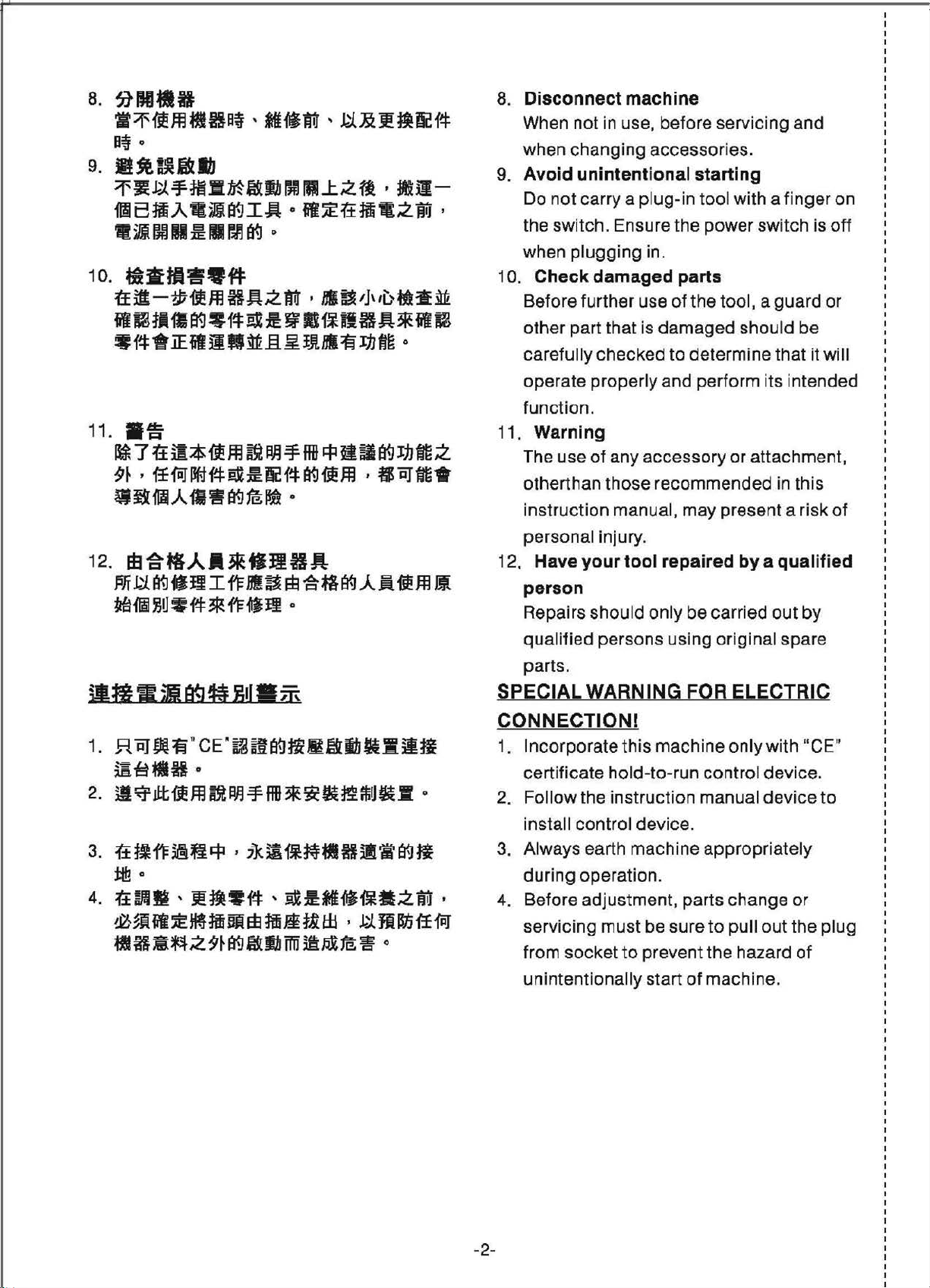
a.
~IHHIB
-~~ffl~H~·-~tt-~&~~~#
ft~
0
9. lti.llBllfJ
~-~~m•M~~~
~BffiAt~~IA
• ill
Im
1111
~
Ill
10.
~----~
tf
il-~-oom
M
l'(.J
HJ:tz
■
LZ~•-~
•
~~~m•zffi,
•
trr
,
mui,1,,t>ffl:~M
w~3•~~~~~w•~~•A*ffl~
*
1i
_.
iE
fil
31
fl~.§.~
!Jtlll
fp1Jfm
0
8. Disconnect machine
When not in use, before servicing
when changing accessories.
9.
Avoid unintentional starting
Do n
ot
carry a plug-in
the switch . Ensure the power switch is off
when plugging in.
10.
Check damaged parts
Before further use
other part that is damaged should be
carefully checked
too
l with a finger on
of
the tool, a guard or
to
determine that it will
and
11
.
■
fi
~7ttm*oom~~~M~ea~~~z
9~
.
1r
fiiI
~f-f
~
:m
~
1i
((.J
{5e
m ,
trRJ
•
fl
1'1
A
ii
w
891B
12.
EB~tlAA*•JIBA
ffi~89-~I~-~~~ffi~Aft00ffl~
fmffl
)JU*
f.f:
*
ft:.
1.
R "iij
00:fi
"
CE"~ifftY.Hi~~ib~-ilil
~!tllff•
2.
~~~oomm~~~•w~~~~•·
~
!I
0
G
w-e
operate properly and perform i
function.
11
. Warning
The use
otherthan those recommended in this
instruction manual, may prese nt a risk
personal injury.
12.
Have
person
Repairs should only be carried out
qua
parts.
SPECIAL WARNING FOR ELECTRIC
CONNECTION!
1.
Incorporate
certificate hold-
2. Follow the ins
of
any accessory
your tool repaired
lified persons using original spare
this
machine only with "CE"
to
-run control device.
tr
uction manual device
ts
intended
or
attachment,
by
a qualified
by
to
of
3.
~~~~§*•~~-~-H~~~~
i:I!!
G
4.
r±RM·~~W#·~~-~~-ZM•
~ffi~~~ffi~WM~mili,~ffi~ff~
ffll
fi
a~
.:z
9~
89
~lb
mHi
~
m;
~
0
install control device.
3. Always earth machine appropriately
during operation.
4.
Before adjustment , parts change or
servicing must be sure to pull out the plug
from socket to prevent the hazard
unintentionally start
-2-
of
machine.
of
Page 7
I
1----------------------------------------------------------------------------------------------- ,
: £jf;~~1llllfflBI.I IMPORTANT SAFETY :
:
~-----------------------------------------------------------------------------------------------·
•a~afl$•a~700~8~M~
ff~~~~~~&~~~~~.~~
~-~~ffim~■H•~ffiflmff~M
~~m~~-·~~~ffi~~~ffl~o
if~
ffl
Hf;
J1t
~
a'A.
~
1±
~
~
RJl
ffl
((.j
ii!?
"jjo
INSTRUCTIONS :
For
0
operating
best
functions
must
operate
and foll
manua
references. We
will
enjoy
1.
ow
l,
enjoy
manufacturing it.
Instead
when
the
and
this
of
you
sa1ely
of
it
instructions
keep it
machine
the
use
and
this
machine, you
correctly.
at
are
confident
following
this
machine,
getting
Please
of
this
hand
for
as
much
instructions,
the
read
future
that
as
please
you
we
2.~m•n~•~7~~~mm~~
0
3. ~~~--~~s•~~:i:M~&
0
(S)
5.
06.
~
7.
..
9~
, iiff~M5ilt1t!tff
llll~~-
I!t5'~' ffl~t\1iff~*ffffi~ajl
c ,
.1-1
oo
~~•
!I~~
,
11J~m•a
RI
.1.~u1
ittlll~J;x~fl=~ilat
ffi!
11
~
11
ic
It
fvUit
, tt
:i: li!
fflf"F
~
11=
~
'.:f'
•:ft~~
EB
~
ft-O"J
0
~
iI
it
~
a/II
ii
W~.A.R~il
Jtttl ill
tifl=
~ 7 ~
/JI
O
½ ,
nt
0
,
&"i
M ;z
fftHI~
mz
ne
Jilrl!f
~:i:
1)
Jifi
ifil
,
j.j
ji
11=
Ii~½
0
Mo
~~ffi~•ffi~HM~~d~~~
Jm:
(1)
vtta , ilWJ=t , ~:qr~.1.1&
J! •
._-r~•
0
~
~
.i.
Ii
pay atte
measures.
02
03
Before
.
read
instructions.
keep
Before
.
ascertain
standards
country
& 4. When
operation,
must
without
is
not
(S)
06.
&1.
This
5.
properly
your
For
wearing
Please
disconnect
circumstances
(1) When
adjusting
thread
ntion
using this
this
manual
this
manual
using this
that
and
.
the
machine
all
be
ready.
the
specified
allowed.
machine
trained
own
goggles.
turn
off
it
threading
guide(s),
to
the
basic
machine,
and
all
related
In
addition, please
for
future needs.
machine, please
it
conforms
regulations
is
ready for
the
safety
Operate this
must
opera
safety,
the
for
any
of
the
thread
equipments
safety
be
operated
tor.
we
suggest
power
switch
one
of
fo
llow
needle(s)
Take-up(s),
and/
safety
please
with
safety
of
your
machine
devices
the
ings :
,
or
by
you
or
a
replacing
(2)
J!ittt
tt
'ft!!
,
~A
l:t ,
PJ!Pll
1W
~~it~
, ttt& ·
'
-~?#ffi
O
igA
•
~&it
, ffi
-3-
(2) When
feet, needle
needle
guides
accessories,
replacing
guards, horns,
and
bobbin(s),
need
plates,
other
parts
les,
feed
cloth
or
presser
dogs,
Page 8
{S)
&
(3)
M~I
11:fey
•
~)GRI~~M~I~~MfflAW
0
IUf
~)~~m•~-~~~~~-~~
fitill 1°'tl
8.
5dlJE,
ii
xat
3'.l:
,
~~~~il~~~.u:
illl a ~Jfr.14
fifli
~Jffl6=
il
J.1
* jft
,
$$Ul
flffl
Bl
Mel!~*Ri ·
111
~!Hrr
&
;z
fii.t
$m
~
0
~
0
(3) When repairing,
(4) When the operator leaves the
ng
worki
machine unattended.
(5) If clutch motors without brake
pads are used, must wait until
the motor stops completely.
If grease, oil, or any fluid contacts
your skin
please wash the
complete ly with clean water and
ult
cons
place
or
eyes
a doctor.
or
leaves the
by
any chance,
co
ntacted area
Or,
swallow any
& 9.
10.
0
I::\
'Y
12.
~~me
&51a11a•~:1:~alffl11t
fflftlrtt1itiz•t-1:9!~cf-l:
,
J.i~
~ir.A.~~11·
MIJ,
~••anriliY-Jf!Sifi~M~liz
• at H
flei&Jl!'lWift,
~
ff
ffl
fli
~
z *
f-1:
ii
EB~
O
at
0
11-=f*f-l:fflJ&ii•Itt~~lEB:il
~1¥-Jtl-=ffiBililiz
~
A
ii~
=tf
&
:tli
flat , a
:rr
~11'
,
~El3~~~JAa
8 ,
~
il
11:
m
•ii,,
11
*
ff:
0
ffl
&_
9. Do not touch any functioning parts
o 1
{S)
{S)
11
12. Maintain and check the electronic
fluid mistakenly, consult a
immediatel
and devices. Always attend to
whether power switch is on or off
before operating in order
anyone from
O.
Qualified technicians are required
for adjustment, modification, and
repair. Only use assigned parts for
replacement.
. Routine maintenance and service
must be performed
persons ,
parts must be
electrician
any electronic part damaged
y.
gett
ing hurts.
by
or
qualified technicians.
done
by
or
well-trained persons. If
doctor
to
prevent
well trained
qua
lified
or
malfunctioned,
immediatel
I::\
\Y
13.
{'ffi•fla!b~~~(@J~&lIHI
ff((.JfllilJ.15i~·If1:Wi, IIWilfi
~-~
fflJ
J.15~
w
~
~
~
~ ~
&
,
II
,
jej
■
~
M
i:p
91
t(:;9~~
1nm
•
-~ffl-J-
ff~
~&~fi~15=
a<1
tt
IUi
(ijj
a12
J..;JJII
II
••it
!lo~~
M&
fl
fi
I::\
'Y
;z 0
14.
1n1-oo.m-natrm
0
JI
0
,
&-m)Ewn•
0
-4-
13. The air hose has
from the machine and the
compressor
of
f before repairing and servicing
cut
the mach ine equipped with
pneumatic parts such as
cylinder. Qualified technicians
well-trained persons are required for
adjustment and repairs.
14. To ensure the best performance,
periodically clean the machine
necessary.
stop
y.
to
or
air supply has
the machine
be detached
to
be
an
air
or
is
Page 9
0
0
15.
lif!•fftm1Emjlf1=.&•Plli~
ti
i:t 5
~
IfI
ni:11!!
..I:.
• •
MA
fl=
ti
ft
J:.
J:.
0
Bfl
I
0
16.
,.~
Ill
if
IIJ:tHI
ll1i
~1t
ti~
ti
ir.J
JI
'iUt-1
~.
ti!!
M ;z
±Ji~
~~
tt
fl
ti~
.
HB
~
tt
~
, ~EB~ -r
1l.
mi~.
ti
o 15. In order
reduce the no ise, please place the
machine flat and level on the ground.
Avoid operating the sewing machine
at
a noisy surrounding.
16
. Select a proper power plug and
0
IC\
install it
connect the power
grounded receptacle.
17
. This machine can only be used
by
to
operate
an electrician. Please
prope
plug
to
rly
a
and
to
for
~
\;:>I
1
a.
~
~
d
fl
J1-~
1,1!i
, ~lli~IIRfi°~(l{J~:i:ffl
,
~
21
dWJ!IIHP/rsl
(
1)
fHl{1=
i!t
•-IB~7il~Mtlzfe:1!1l , ~
~HM~it'aiff~Z9~1i
~Alflt1H~~imz*f1:
JI
ti
Fi.Pf
It~
ff
!.!a-~
jJ:
II
~•-z•
J.IIUi
1:E
1RJ
.A.
1/i
ffl ~
,Ld3
Et
;z
~
ltiHJ
O
11
It~
ffl
~
·
-tl?.:if
0
'.IE
\:::I the designed purpose. Othe r uses
this machine are not allowed.
IC'\ 18. Any
\::,,
made
conformed with the safety standards
and regulations. Precaution is
necessary. No responsibility will
company take for damages caused
by
this machine without permission .
19
.
applied
mod
ification
on this machine
any
mod
ification
Two
safety warning signs are
as
warni
ng
(1) For
the
safety
service
open
control boxes of
devices and
pe
rsons, please
the
cover
don't
or
conversion
must
or
conversion
signs:
of
operators
of
any electronic
mo
tor or other
touch
be
don
any
our
and
't
of
of
(2) ~~~~U>iiUJJ14
a. M
~
=f
i:iJ
tt
3
lffl
ffi1iit~d~½~f-F~
fi.
ff~
fl=
'
j.j
~1'io
b.
~
7
li!aflHIHilfi
Bi1'91fi ,
~lli •
}lf;it ;
jij
tit_. t£
.A.A~11
1m
89.=J: , BIU.Jl
-~-~ti&•Jsl•}1
lft9~~@${iLffjj
fRJ
4tl
£ ,
°
Bl
fli a ,
,
~.ft.A.
,
1'1\1
Iii
J.j
!~)I
=J:
31
i!
=f
ft
components inside
e
le
ctrical sh
(2) Always
a. Please never
machine w
finger guard
device
injury.
b. Please keep your hair, fingers
and
hand wheel, V belt and
while
op
eration,
put
to
prevent the ri
by
tangled
ock
keep
in mind :
it
to
avoid physical
clot
hs away from the
the
machine is in
as
anything near these parts,
into
to
avoid
hazards.
operate
hout belt
or
any safety
well as never
them.
sk
of injuri
cove
this
r,
motor
es
-5-
Page 10
~
c. •
1t1UJ
lffl
11
EH'±
rt
ffl
i:f:I
-=¥-
nt
t£
tt
B9
~9~mi:f:I
,
1! 0
d.
Wliffilifi~
lb,
~7ii!~f.t.:J:AJfls
;z e
~
,
!!!HR
~m•tt~a11t-HLE
I!
ti~
T
~
81i11M
• 0
· J.1~9Jft.A..R~
~
Im
Ill
fl~
ti~
,
~
1"
AJ
JM
iflHrtl
"""F
n
:ex
tt
•~al
J-i~•BA.I.~
, tfmii!iilM
l®
ii
:i'.1fa
a<J
.:f
ii
•
11t9~
, a
,
ii
:i'.
~jjt
lffl
IHI
a\
c. Please never
under
thread
prevent physical injuries when
you turn on
or operate
d. While
operation,
a hi
your
area
po
In addition, please
to
the needle(s)
take-up
the
gh
speed
hands away
of
hook
tential injury to
turn
off
put
your fingers
or
cover to
the
power swit
the
machine.
machine is in
the
hook rotat
. Please
to
prevent any
the
power
keep
from
your
make
of
in the
the
hands .
the
ch
es
at
sure
a\
a\
A
e.
S!Rm:aJtHU!Hlejitlf
~Hll
=¥-
II
M
ti
ft
i:f:I
B.A.A~11
t.
~
7
31!t~ltH~~Ail1Jffii
~lmlt9~ ,
im
m
~a~
tlfttlll
11
0
g.
~
m
1&H1<.i
..
Sflimfti~~S
mm~
, J-j~9Jft.A.ff.~
ffl!
w
~
a~x
it,ljff~Dll:~8~·~
jj;m:f•~~Plftir-.J ,
m~•w~~iilb
~-9~
jJj 0
,
1t•11~f1Bt
' lj\,i:)
•
J.j
,
~
fn.l
rm i3I
~
9J
~I
11
ti
Iii~
li
7
®AJ
ffi
a\
a\
A
machine whi
bobbins
e. Be careful and
your
fingers inside
machine
lifting
avoid
injuries.
f.
Please turn
be
head
cover
possible
abrupt
g. For machines
motors, the m
produce
machines are at rest.
Therefore, please turn
power of
the
possible
fore tilting the
or
and
le
changing
.
do not place
when placing
machine head
phys
off
the
removing
the V be
accidents
start
of
this
equipped
otors
noise while the
this
machine
the
or
to
ical
powe
r
machine
the
belt
lt
to
avoid
due
to
machine
servo
do
not
off
to
.
the
avoid
to abr
h.
~
7
A
lf~MtizffiJft , •M
1"
~tt
3 1Uli%Hlttf!IHl
fl
A
{1:tlff O
-6-
h. Never
machine after the
is removed
shock
possible
upt
start of
ope
rate the
to
hazards.
accidents
the
machine.
sew
ground
avoid
electrica
due
ing
wire
l
Page 11
A
i.
~ 7 M:t.11ill~llr*1f
mi
~
I g
;z
"iij
fffi
1l
9~
,
~jljjt
'
:jij•J:.!2fRtf•ai
~
5t
fafi
+JJ
llf
Q
i.
Please turn t
before connecting
disconnecting the power plug to
pr
event possible
to
electric
el
ectronic components.
he
pow
acc
shoc
k or damaged
er switch off
or
idents
due
------------------------------------------------------------------------------------------------
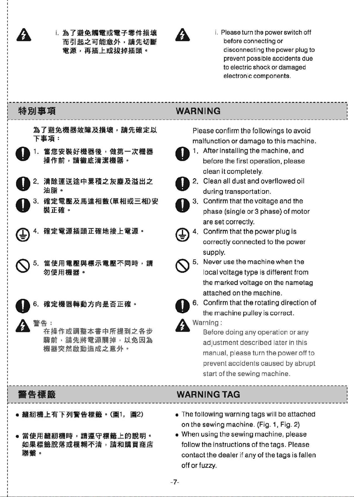
WARNING
r - - - - - ---- - - - - - - - - - -
~7B~MB~s~•~•-$t•~~
~*lfi
1
0
02
.
.
03.
:
-~~~~Sftffl,~ffl-~
~11:frl , illtJg$i;i*M
~litili!~~-~2.PJ!ll»m:±L:z.
0
5feHli
il'.itS
~iEil
---
- - - - - - - - - - - - - - - - - - - - - - - - - - - - - - ---- - - - - - - - - - - - - ~ - - - - - - - - - -
Pl
ease confirm the followings to avoid
malfuncti
■
H
0
o
1.
After installing the machine, and
be
clean
o 2. Clean all
during transportation.
■
~milffil&(Itiffi~-=ffi)~
O
03
@4·
Confirm that the voltag e and the
.
phase (single
are
Confirm that the power
correc
supply.
Never
-'-~-
- - - - - - - - - - - - - •
on
or damage to this machine.
fore the first operation, please
it
completely.
dust
and overflowed oil
or
3 phase)
set
correctly.
tly
connected to the power
use the machine when the
of
plug
motor
is
1
I
local voltage type is different from
the marked voltage on the nametag
attached on the mach ine.
06. -~•HMDn~~a~~
0
0
A
•s
.-.a
■
*ti
r-----------------------------------------------------------------------------------------------
-~~ffl-~M~
~---~~~-N~-.~~--ff~
JflB
·
•
r±
ti
11=
ex
a111
m *
~
q:,
1n
m
111
z
a-$
llfrl ,
tilH~~fflllhii,,;xzM11~
■ WARNING TAG :
o
~St~fljjrHI~
•
ffl•~--J:.~~M
·
J.j_~~l\
0
.-
"-"
0
A Warning:
• The following warning t
• When using
6. Confirm that the rotating
the mach
Be
fore
adjustment described later in this
manual, please turn the power off
prevent accidents caused by abrupt
start
on
the sewing machine. {Fig. 1, Fig. 2)
ol
low the instructions of the tags. Please
f
contact the
ine pu
doing
of
the sewing machine .
the
sewing machine, please
dea
ler if any
lley is correct.
any
ope
ration or any
ags
will be attached
of
the
tags
direct
is fallen
ion of
,-
to
.--
I
I
•
off
or
fuzzy.
-7-
Page 12
®
LDJ~~
........
aaa5.»lltMm!IH
T
cu:hi'9
presart
T
U'Tl
befae
@@
@~
~½1~ilf&X(lil3)
(A)
~ffi
~D~-~~~.~~~--~~D~~
/jj{~
0
~~ftlbnfi:il
ilffiH
aeas
ca,
off rra,
q:l81~
1l
tfl!
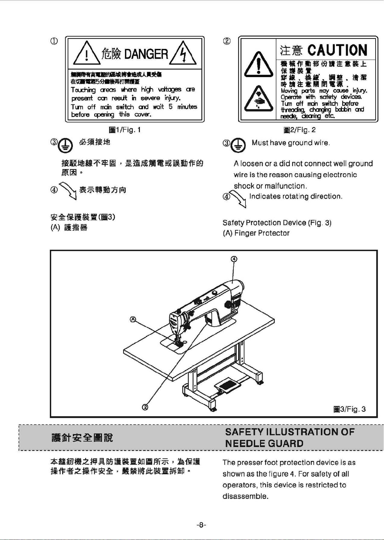
DANGER
~.ff
wt-a'e
resut
switch
'this
lil1/Fig. 1
hig1 vdta]es
i'I
severe injuy.
ax:.!
a:MK.
wait
&
ae
5 mirules
~!!!
CAUTION
•t1-fflli!S{~•~••.1:
&
A
-1¥t1••
l!jl.tlil'.WIJ!f.lill
Of,
at
~
a Ill
Mov
i~
Operate
T l.ffl aff
1tYeocirg
neede.
perts
dea,ioo
112/Fig
with
rrrin
~
. 2
"1
rray
safety
switch
@@ Must have ground wire.
A loosen
wire is
shock
®~ Indicates rotating
Safety Protecti
(A)
Finger Pro
or a did
the
reason causing electronic
or
malfunction.
on
tecto
not
connect
di
rection.
Device {Fig. 3)
r
•
ii
ca.ise
bctbh
well
.
•
i"IJu-y
devices.
befae
CJ1d
ground
.
;
-------------
!
:
____________
■
~-~•z~R~~R•M
~~~2~~~½·M»M~~-m~
--------
tt;;:i:
__
---
--------------
■
mt
____________________________________________________________________
-----
■~~.~~~
0
-8-
SAFETY ILLUSTRATION
NEEDLE
The presser
shown
operators, this device is restricted
disassemb
as
the figure 4. For safety
GUARD
foot
protection
le.
dev
113/Fig
OF
ice is
of
all
to
. 3
_
as
Page 13
114/Fig.
4
---------------------------------------------------------------------------------
r
-------
-
-----------
-
-------------------------
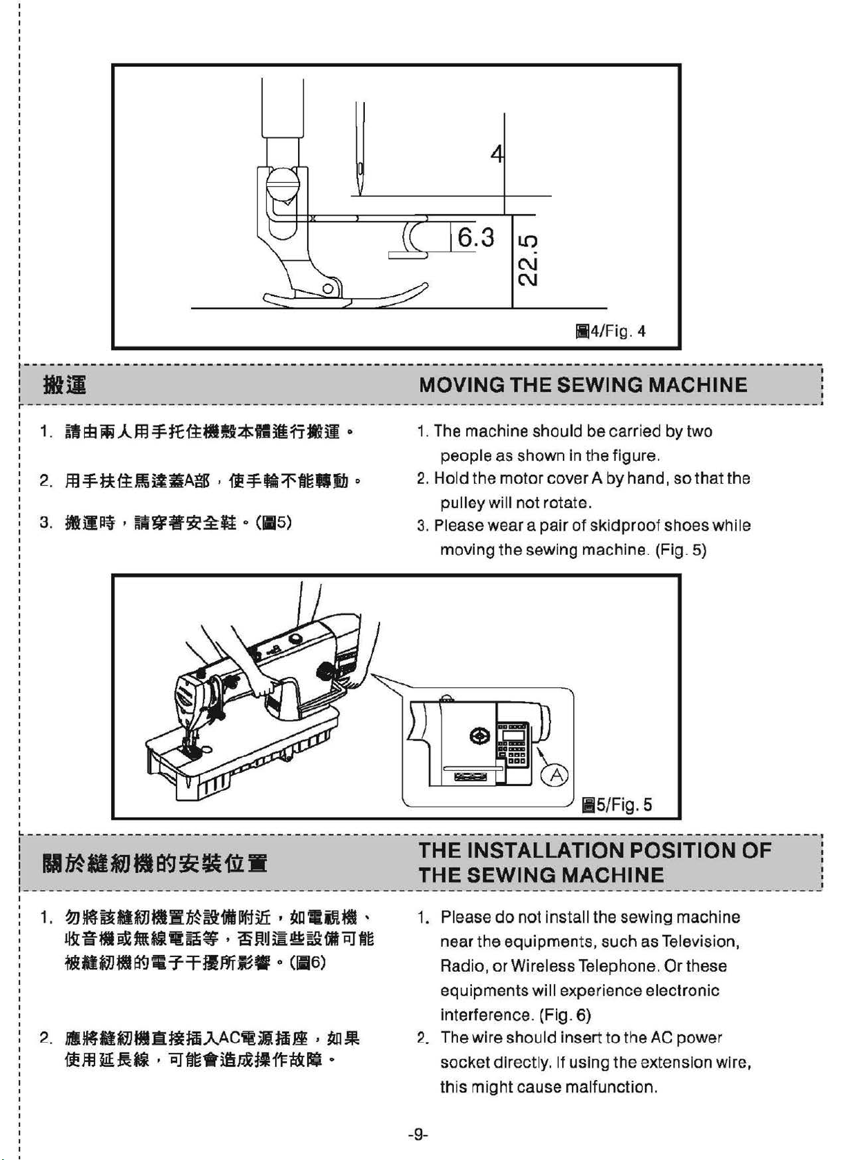
MOVING THE SEWING MACHINE
----
----------------
1. The machine should be carried
people
2.
Hold
pulley will not rotate.
3. Please wear a
moving the sewing machine. (Fig.
the
as
shown in the figure.
motor
-
----------------
cover A
pair
of
by
sk i
dproof
by
hand,
shoes whi le
so
two
that
5)
---- -------
the
I
- - •
------
L-----------------------------------------------------------------------------------------------1
:,:
1 THE SEWING MACHINE
~•••~ii:•m•
11
1.
-~~-~-~M~-~fi•~-~--
~fi•~-~~~~•~m~@~-cJ~
--~■ir.Jtlf-=ffl.ln~·
2.
hl~M~tlAffHmAACtiiitl~
{fffl
~~ii I cJfm.iftJiil:111:i!&lll
0
(116)
,
rul.
0
THE 1NsTALLAT10N Pos1T10N
1. Please
near
Radio,
equipments will experience electronic
interferen
2. The wire should insert
socket
this
-9-
do
not install the sewing machine
the equipments, such as Television,
or
Wireless Telephone. Or these
ce
. (Fig. 6}
directly.
might
cause malfunction.
115/Fig.
to
the
If using the extension wire,
5
AC
power
oF
I
Page 14
X
l::J~
116/Fig. 6
I
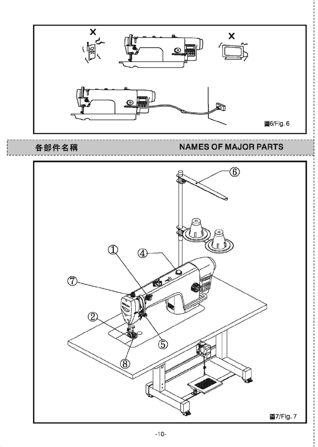
: 4fl~f-l:~ M NAMES
I I
------------------------------------------------------------------------------
OF
MAJOR PARTS :
•-----------------------------------------------------------------------------------------------,
@
1
I
-10-
117/Fig.
7
Page 15
CD
®
@
W'1M-
llll:R
5dla
Q)
Thread
® Presser
@Oil
Windows
Guide
Foot
@
tll•
M
@ll~
:ti:
:i: 1i ~
(7)
ll!i~IJ1.iil•
@ ~ffiH
••
~
1M
!!f
~
Threa
@
® Thread St
Safety
(J)
Thread Take-up
®
Finger
d Tension
and
Protection
Guard
Adjusting
Devices
Cover
Set
----------------------------------------------------------------------------------------------- ,
M.M
SPECIFICATIONS :
l-----------------------------------------------------------------------------------------------·
'-i B &
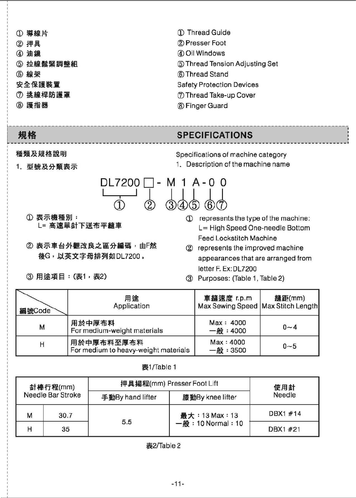
1.
:tJU!
~
aJJ
~~&~Mfi,j\
DL7200
1
1
CD
Specifications
1.
□
-M 1
~
~4ck
Description
A-
0 0
4~
<D
represents
L=
High
of
machine
of
the
the
Speed
mach
type
One
category
ine
name
of
the
mach
-needle
ine:
Bottom
CID
~~-~9~1leillZWdtliHI
flG •
J..j_~)t~-fin~91JR!l
~
M
H
ti~fi~(mm)
Needle
Bar Stroke
,
EBF~
DL7200 o
m~
Applica
m
~
qi
i,:
=Ai~
For
medium-weight
ffi'M~~ffi~~~1'i'~
For
medium
to
heavy-weight materials
.:¥,IIJBy
tion
materials
flJIAm~(mm) Presser Foot Lift
hand
~1
/Table 1
lifter
Feed
® represents
appearances
letter
@ Purposes: (Table 1, Table 2)
Max Sewing
Lockstitch
F.
$Sil~
Max:
-Ji: :
Max:
-~:
Machine
the
improved
that
Ex: DL72O0
r.
p.m
Speed
4000
4000
4000
3500
are
arranged
Mie(mm)
Max Stitch Length
ifffltt
DIIIJBy
knee
lifter
Needle
machine
from
0-4
0-5
M
H 35 DBX1
30.7
5.5
-~:
~2/Table2
-11-
A* :
10
13
Max
Norma
: 13
l : 10
DBX1
#14
#21
Page 16
©
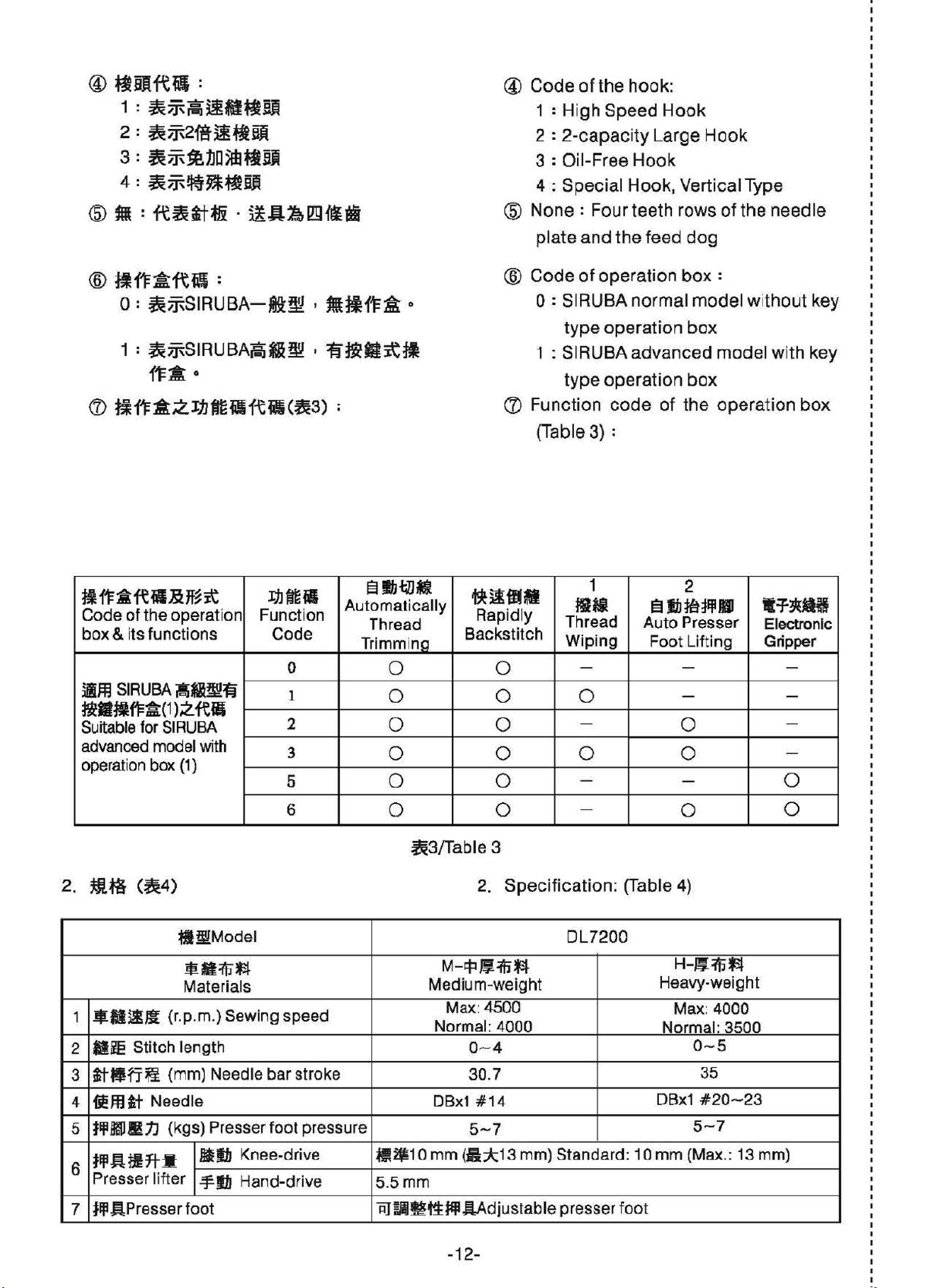
~Dfciil:
1 :
~;J\~~-f:t~
2 : ~;J\2,fA-iiftBli
3:
~;J\
4 :
<ID
M :
®
~fF~ftfl:
O:
1 :
~1.J□5fb
~;]\!jt~~~
fc~tt
~;J\SIRUBA-6:~
~;J\S
IRUBAF-iM~ ,
ttBJi
ffi · i!A~
{'¥* 0
(7)
fifF*~li1ftll{tii(~3)
lrn{ld
, ffltjl{
~:li-~r,I
:
'f
A
©
Code
@
None
@
Code
0
({) Function code of the operation
of t
he
hook:
1 : Hi
gh
Speed
2 :
2-capaci
3 : Oil-Free
4:
Special Hook, Ver
: Four
plate
and
of
0 : SIRUBA n
t
ype
1 : SIRUBA
t
ype
(Table 3) :
ty
Hook
teeth
the
ope
ration
operation box
advanced
operation
Hook
Large
feed dog
ormal model without key
Hook
tical Ty
rows
of
box
:
model with
box
the
pe
need
le
key
box
fl
fl::&-re
Code
box & i
•m
tR■ll
Suitable for SI
advanced model with
operation box
2.
ffl~
1 •ll~m {
lllie Stitch
2
3
it•n
4
I!
t
ljl
5
tlfl.atlft-I
6
Presse r lifter
ii
& Jf~it
of the operation Function
ts func
SIRUBA
f1=a
(1
(~4)
jljff
)Z
RUBA
(1)
WiW.Model
r.
lengt
~ (mm) Needle
.lfl
tt
Needle
Bl!IJl!t.l
(kgs) Presser foot pressure
11.J~-
tions
~
f\!
tl
•·*~
Materials
p.m.) Sewing speed
h 0~ 4
Code
0
1
2
3
5
6
bar
stroke
ellbtJlMl
Automatically
Thread
Tr
immina
0
0
0
0
0
0
~3/Table3
llilb Knee-drive l!UJ10 mm (
.:f
111
Hand-drive 5.
5mm
~ilfflM
Rapidly
Backstitch
0
0 0
0
0 0 0
0
0
2. Specification : (Table 4)
M-q:i~i1J'3J
Medium-weight
Max: 4500
Normal: 4000
30.7
0Bx1 #14
5~7
fi*1
3 mm) Standard: 10
1
ff
Hi
Thr
ea
d
Wiping
2
El
lb
1a ~Ill
1111
Auto Presser
Foot Lifting
- - -
- -
-
-
-
DL7200
0
- 0
0
H-~1\j"f:I
0~5
35
#20
5~7
ght
- 23
Heavy-wei
Max: 4000
Normal: 3500
DBx1
mm
(Max.: 13 mm)
t=f~
Electronic
G
ri
pper
-
-
0
tlflAPressar
7
foot
AJ~~tt
~
AA
djustable presser fo
-12-
ot
Page 17
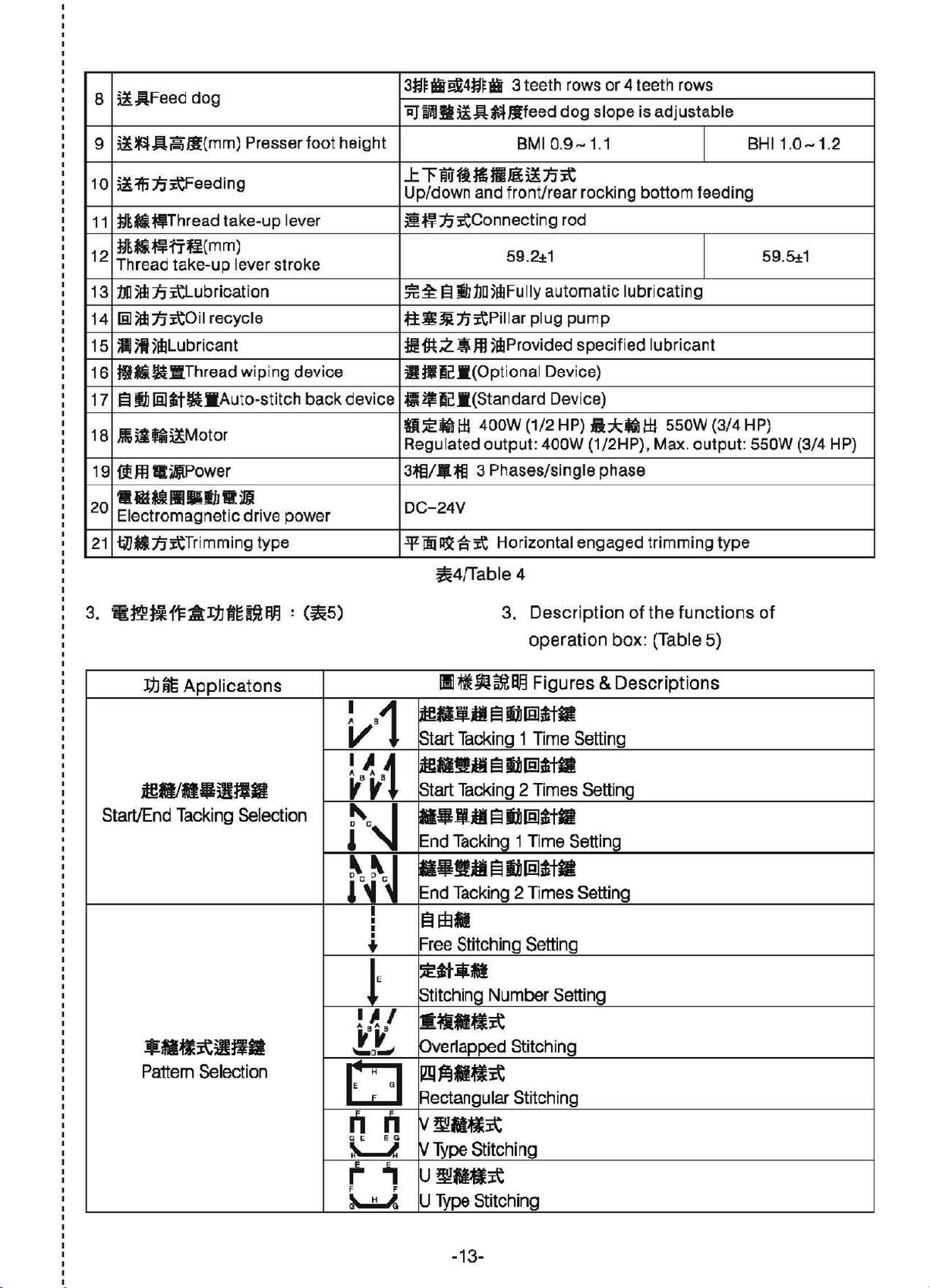
~AFeed
8
dog
3i~ii~4~~ii 3
'iij~gi!A~Jlfeed
teeth
rows or 4
dog
slope
teet
h rows
is
adjustable
~~AjijJ'B(
9
10
~1'11.fitFeeding
11
~-
•Thread
~-~fi~{
12
Thread
1Jl
5111
13
14
15
16
17
18
19
20
21
jj
IBl
,din
•
;I
5dlLubri
ffltlllilll.Thread wiping
~
jJJ
la)
ffiitffi~Motor
{flfl
.i,!{Power
•&Uilll■lb•~
El
ectromagnetic
t}Jflnit
m
m) Presser
take-up
m
m)
take-up lever
~Lubrication
itO
il recycle
cant
atl!t•Auto-stitch
Tri
mming
foot height
lever
stroke
device
back
drive power
type
device
BMI
0.9~ 1.1
..I:
"""F
mi
ff
i&
tl'Ul
~
:rr
it
Up/down and
jffi~:fj~Connect
~~
~
lb1JD511lFully
tt.lUitnitPillar
~#tZW..lfl 5dlProvided
111112I(Optional Device)
11~12I(S
o~•uu
Regulated
3ffl/•ffi
DC-24V
!flffii~~rC
~4/Table4
fro
nt/rear rocking
ing
rod
59.2±1 59.5±1
automatic
plug
pump
specified
tandard Device)
400W (1/2 HP)
outpu
t: 400W (1/2HP),
3 Phases/single
Hor
izont
•*•lli
al
engaged
bott
lubricating
phase
om
feeding
lubricant
550W (3/4 HP)
Max. output:
trimming
type
BHI
1.0~1.2
550W (3/4 HP)
~~
~M/8.iljtll
St
art/End
•••
Pattern
Applicatons
Tacking Selection
;:tjl~-
Selection
lll~W~Bi.l
iffllU1UI 811!1Eiltttl
1,,,
91
Start
Tackin
ifflMWtl
~B
,~91
Start Tacking 2
~•¥a
tc~
~~
1 Ci C'
I
•
•
•
♦
E
!
~
ta
t'
'-o-...,,
□
Ii
Ii
E G
GE
~
.,
f
F F
~ H ~
nd
Tacking
···-~l:IJ
E
nd
Tacking 2 Times Setting
EI
EEM
Fr
ee
Stitching
~ti
-•
Stitching
/
••••
Over1apped St itching
~
~--it
Rectangu
V ffl!M•it
V T
ype
U~Hit
U T
ype
3. Descripti
operation box: (Table 5)
Figures & Descriptions
g 1
Time
El
11J
lel
tt11
Times Setting
El
i1Jlelttil
1 T
ime
(g]
ffll
Sett
ing
Number Setting
it
lar Stitching
Sti
tching
Sti
tching
on
Setting
Setti
ng
of the functions
of
-13-
Page 18

ne
Shot Automatic Stitchin
ljJlf~m~•
Optional Functions Selection
utomat
Needle UP/DOWN
~5/Table
ic Thread Trim
5
ming
,-----------------------------------------------------------------------------------------------~
: IMPORTANT SAFETY !
,
I -----------------------------------------
llll~*
1.
lli111=¥
( 1 ) .
(2). iii.A~~
(3). ffl
2.
ffilff{1=~
(1). MH1'iffflfey, Rlffll31ill~~Jt!J
(2).
■
B9•1!~:i:5±aSJ1t
if
ffl ~:a=~
~ii
0
"'1
it
ir-.J
ii
J'J
Ii
ll@II $ ffl R
0
~tt•~=.A.ffl!f~ffiltJIUI
..I:
0
IUt!iftffM~M45°C.l-~.t.l:.a(J~j&
INSTRUCTIONS
--
----------------------------------------------------1
1.
T
ranspo
(1). The
(2).
0
0
(3).
2.
Storage
(1
}. The machine must use duster cove r
(2). The
rtation
machine
covers
polystyrene
Put
Use a cart
move
to
that
the
machine
it.
cover
machine
it when
packed
made
to
or
by
avo
OF
THIS
with two
of
expanded
protect
into a carton.
two
it
did
id
it.
men's
not
to
storage
MACHINE!
piece
hands
work
.
in
to
the
3.
fl:.~
SH1'~~~~40°C.l-~L.l:.ir-.JjAJiI
4
.•
~
:a
$i
~
J.1
"f •
;J\
m :1 s
( 1 ) . I
~-
(3). Wt±~1'lr~99~ji-~1Jo,J,,D-
{1=
11
~
:m:
ffl;
!It!
=•nffl~~~~~~~~~~~~
■
ti
D
l1i
ir-.J
0
o
~-~-~¥ffi.QtiW~~-•~MA
;ZIIJ
0
r±
ffi!i
li
( 1 ) .
W 'a-tt
fl
fJi1
lb~
~
z
tf6
'3-
14
,
!ft
~
$1
$1
it
ii
.0
~-
V~·••·=~-~~~.a~•
Iii
m • jJi
0
0
R
{1=
..l:.1i
0
0
at~
temperature
3.
Working
The
machine
4.
Warni
Pay
followings:
(1
(2).
(3}. Be careful
(4).
Pay
(1
(2). Pull
ng
attention
).
Wor
Never
is still
Do
needle
fabric.
attention
).
Movable
guard
adjust, thread,
king
touch
running
not
when
out
more
doesn't
to this warning
area
if
insert
and
to
parts
the plug
work over
is
dangerous
the
needle
.
you
infeed
your
finger
roller for
the
warning
must
you
operate
from
change
than
45
°C.
40°C.
advice
.
if
the
machine
fabric.
between
transportation
sticker.
be
enclosed wit
.
socket
when
bobbin
as
and
the
on
h
you
needle
-14-
clean.
Page 19
INSTALLATION
r------------------------------------------------------------------------------------------ ---
--l
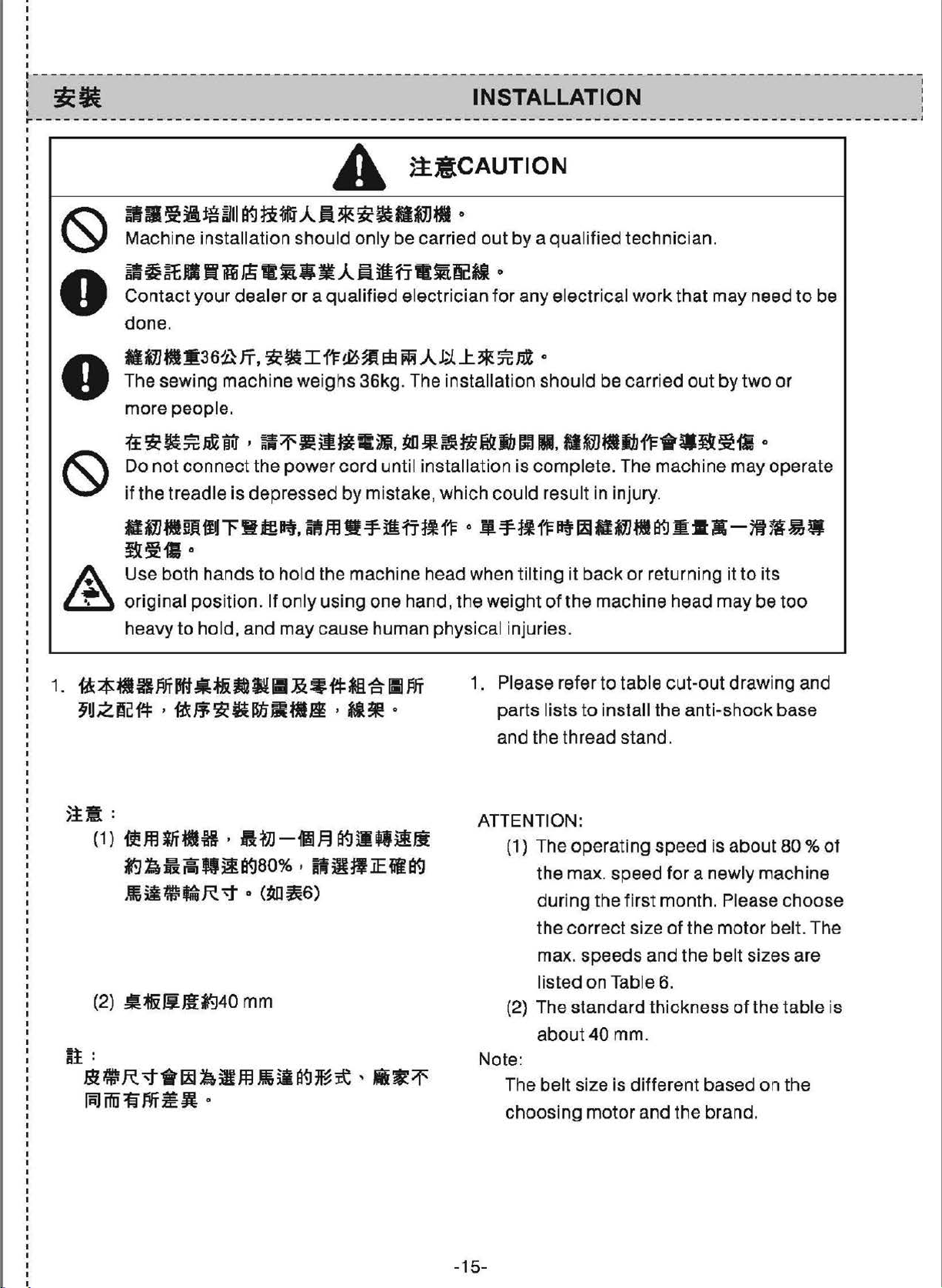
~-~~-~~~ffiAfl•~~-~-
Machine installation
~~~Sflfi~-~-~A~~fi•~~M
Contact
done.
M
i1J
M
The sewing machine weighs 36kg . The installati
mo
•
A Use both
~
re
ttic~~~iliI
Do
not
if
the
Mi1J■~ffl~Hffl~.amw~~ff~~
!i~-fl
original
heavy
your
dealer
•3
621
fi
people
connect the
treadle
to hold,
0
hands
pos
.
is
ition. If
should only
or a qualified
,
~
il
I
ft&-~
,
~~iU!fiCj]j,
power
depressed
to hold
only
and
may caus
cord
by
the
machine head when tilting
using
0
be
carried
electrician f
Eb
~ A
J.;1
J:.
tal:~~flt~Jblffl
until installation
mistake,
one hand,
e human
which
the
phy
out
by a
qua
lified
technic
0
or
any
3R
electrical
0
:it;
Pl
on
should be carried
work
Ill, M~fflllbfl=•W~~il
is
comple
could
0
-~~~~~-~-~ffi•K-~~~
weight
sical injuries.
res
of
te. The machine
ult
in injury.
it
back
or
the
machine
ian.
that
may
out
returning
head
by
two
may
it
to
may
need
0
operate
its
be
or
too
to
be
1.
~~ffllBM~-~ffiR
~~~~.~~~K~--~•M•o
)it:
(1)
ilffl
lfillH , AM-MF.I a<JilQ~Ji
■
&~~ffi~~M
~~~~-~8<]00%,ff~-~-~
.
~ii~-R'1"
(2)
:!lfi~m~40
0
(~~6)
mm
fi:
m~R~•~~•m~~~~~-•~~
~fffiliJYf~Ji O
1. Please ref
parts lists
a
nd
the thread stand.
ATTENTION:
(1)
(2)
Note:
The bel t size is different
choosing
er
to
table
to install the
The operati
the
max
. speed
d
uring
the
max. speeds
li
sted
The
about40
the first month. Ple
correc
standa
t size
on Table 6.
mm.
motor and
cut-out
anti-shock
ng
speed
and
rd thickness
is
for
a newly machine
of
the
motor
the
belt sizes
based
the
brand.
drawing
base
about
of
80
ase choose
belt. The
are
the
table
on
the
and
%
of
is
-15-
Page 20

------------------------------------------------------------------------------------------------,
I I
: 5mllii:C
I I
OIL
PAN INSTALLATION :
•-----------------------------------------------------------------------------------------------,
I
I
CD
1. The corners
placed
groove
on
of
the
the
of
the oil reservo ir has
four
corners
machine
at
table. (Fig. 9)
CD
to
the
cut
out
1119/Fig.
be
9
2.
ffl~■M~Z~T®•~~-•mm©~
'.AEM
A
~(~-f1=fl1.iltiJ)
~--~~M~~~@~~MB~~~
8~1ili:iJ), ~ffl.iliHf~M@'1tJ:.
, Mfff
lttllli~DI
0
(lil10)
2. Use nails ®
seats
Use
rubber
cushion seats ® on
B).
Place oil
seats. (Fig. 1
4
Q)
as
on
side
based
reservoir@
O)
19.5
mm
illustrated
A(the
operator
adhesive
the
hinge
to
fix
two
rubber
's side).
to
fix
two
side (side
on the fixed
-------
---
A
-16-
s-----11~
■
10/Fig.
10
Page 21

3.
~~-~-~~MA~-~~@~M•~
~~-©~~-~~ffi~~R~•~KW
~-~-Mffiffi~---g~®~=MH
□
i:f=1
°
(11111
' 1
2)
3. Place the
holes before
onto
Then, install the machine head
the
hinge
four
<D
into
placing
cushions
the
(ID
the
two
machine
of
the desk.
fixi
ng
head
onto
the
machine
rubber
cush
bed
ion®
that
has
two
openings
of
each. (Fig. 11, 12)
11111/Fig.
with
11
lil12/Fig.
·------------------------------------------------------------------------------------------------.
I I
:
I 1
1------------------------------------------------------------------------------------------------
tf-Qgic&
~~-~$~ffifl~ffi~ft~M~~
~iiJJt,
~WJRQ~Rtt
O
{11113)
0
~R
INSTALLING THE NEEDLE :
Choose a right
type
of
used. Turn
needle. (Fig. 13)
-17-
the
needle size
thread and
the
powe
r off
according
the
type
befo
of
the material
re
placing
to
12
the
the
Page 22

~~-fflffi~~~Mffl~-~~~ti
~-~
, 1ilffl~~-ti
O
(1113)
0
~g
Choose a
type
of
the
right
needle si
thread
and
ze
the
type
according
of
the
to
the
materia
l
used. Turn the
needle. {Fig. 13)
1.
Turn
1.
-~~-~tt•~~fl~--~o
2.
~--~®~~~ti©•OOXtim~~~
2. Loosen
ffiA~~OO~~nB0~~~tiZ~~C
il'Jriili:iJli:
D
0
the
bar
to
with
its
right in
long
groove c
exactly
power
hand
its
highest
screw®, and
indented
direction
to
the left in
off
wheel
position.
side A facing
B,
of
the needle
before
to
hold
and
direction
placing
raise the needle
the
needl
exactly
make
sure
is
facing
D.
the
e(!)
to
that
-· - o
:t
I
I
--A
B
11113/Fig
. 13
-18-
Page 23

I
I
I
I
L-----------------------------------------------------------------------------------------------1
I I
:
"l~Zii:li
SETTING
THE
BOBBIN :
1----------------------------------------------------------------------------------------------- I
1.
~~~r~~-~•~M•n~~M~~
0
1.i
[ci]
(Ii
14)
2.
~ti·9~M~A••~~C1.i~~-•
~~•ti~~~~-~ffla©•tt~B~
tfi.1!
□
91±10
3.
~~c~•~•~r~-•~~~ffi1.i~
MiJJ
0
/J
1. Set the
way that
clockw
2. Pass the thread
pull the thread in direction
will
and
3. Be sure the
as
toward c.
bobbin
the thread
ise. (Fig. 14}
be
pulled
will be pulled
the arrow shows when thread is pulled
in the
through
under
out
bobbin
bobb
in case in the
wound direction is
thread slit
C.
the
tension spring Q)
from
notch
rotates in the direction
A,
and
The thread
B.
C
1114/Fig.
14
-19-
Page 24

.---
- - -
-------------------------------------------------------------------------
-
---------------~
I
:
--~-
THREAD STAND ASSEMBLY I
'------ ---------------------- ---------- -------------------------------------------
1.
Assemble the thread stand
inst..a.U.ing
the
hole on
. Place the thread stand set onto
the
tab
le
top
2. Fix the thread stand with a nut
top
under the table
.
set
. (Fig. 16)
CD
---~
before
loc
--------
ked
-;
-2
0-
11
16/Fig. 16
Page 25

I
I
I
I
I
,-------------------------------------------------------- -
1 I
l
11&9111
\ I
r
------------------------
~
---~-------------
THREADING THE MACHINE :
-
------------------
---
-----------------------------
-
---------------------------------
----
---
•
li
18/Fig.
l ttffilll.ll! STITCH LENGTH ADJUSTMENT
I
~---
--------------------------------------------------------------------------------------------·
1.
~~~~~~~-~-~~~B
W
•tt~
m~•*w~•~ A O c1119)
2. JHl&H..clUII¥iiZ:!:iHI
3.
~~~~-~~·-~-~~~&©·~
Pl}ffj&ff
®tt"""F
■
0
~
1. Turn stitch length
indicates
align with mark A on the machine.
(Fi
g.19)
2.
The calibration on the
3. Press the feed lever ®
stitch length a
stitch length.
to
dia
l ill as the arrow
have the desired
dial
is millimeters.
down
dj
ustment dial
number
and turn the
(D
to
change
18
-21-
Page 26

1119/Fig
. 19
,-----------------------------------------------------------------------------------------------1
:
: z · PRESSER
IJl~~AaftllZD.UI
ADJUSTMENT
FOOT
OF
KNEE-CONTROL
LIFTER
I-----------------------------------------------------------------------------------------------
1.
~m•~~am*H•~~~~Amff~
)Jr~10mm
2.
~~~m•a~~~*•~~•~ID•M
~JU.1~~13mm
3.
i?~A&IJ~•llffl~10mm~
O
(1120, 1121)
0
• iifil~tf-
•u:~aB®~altfll!H,A@J:.$
The standard lifting height is
1.
using knee-control presser foot lifter.
(Fig.20, Fig. 21)
By
2.
3.
0
adjusting the screw
control ler, the presser foot can be lifted
to 13mm.
When the presser foot is adjusted to
lifted over 10mm, assure the
of the needle bar
does not hit the presser foot.
<ID
<D
in
its
lower position@
1 0 mm by
at the knee
bot
tom end
up
be
-22-
lii20
/Fig. 20
Page 27

11121/Fig.
21
----------------------------------------------------------------------------------------------·
NEEDLE THREAD/BOBBIN THREAD
TENSION ADJUSTMENT
--------------------------------------------------------------------------~--------------------l
1.
ttallli.ll!'il!a(lii22)
(1) ~J~~at151Rl(A 1.ifFil)tilhtiliBII
~~&Q.),~M~SUti~~---
~o
~;m!tiil151RJ(B
(2)
~tUl!Q.),
(3) ~1~~&15ra:J(C
~:t;HH®, &tMB!RJlW!R
(
4)
~~~&11.i!Rl(D
~$UM®
2.
~M<~•)R!Rll~~
( 1 )
it<
Iii
Iii
ii
15
(2)
-~@
~i!lffil
■
M@
,
~lllBIUll!M
1.ilRJ( F 1.iraJ)QlbllR~:tU
, Jlllll111Jll!U
,
15raJ)ttlbtifiUM
1t•W:Ei
0
nfi:iJ)fflbit-MllM
15
fRJ)fflhti~IIM
ttlili!lllWft
ftiJ
( E 1i
faJ)
ff
ltJ
0
0
0
0
8
IU!
ffiU
1. Needle thread tension adjustment (Fig.
22)
(1) The
(2) The left thread tail will be longer, as
(3) Increase the tension on needle thread
(4) Reduce the tension on needle thread
Bobbin thread tension adjustment
2.
(1) The
(2) The
lef
t thread tail on the needle will
be
sho
rter after thread trimmed as you
turn thread tension nut Q)clockwise.
(in A
thread tension nut
clockwise (in B direction).
by
clockwise (in C direction).
by
counter clockwise (in D direction).
increased as tension
is turned clockwise (in E direction).
reduced as screw
direct
turning thread tension
turning thread tension
bobbin
bobbin
ion)
Q)
is turned counter
thread tension will be
adjust
th read tension will be
Q)
is turn
nut®
nut®
screw@
ed
counter-
1
I
I
I
clockwise (in F direction).
-23-
Page 28

11122/Fig.
22
I---------------------------------------------------------------------------------------------
:
: ADJUSTMENT
ifti-tn
■
illJf!
NEEDLE STOP POSITION
•-----------------------------------------------------------------------------------------------
(1)
~~jEMfllll:
-~~~~~A~~-~~M~B~
Jf
(2)
i.Jtt~r~~~ = fffJltiff;{±:uili~
0
HPi:iJ
MrJ!M~CD
·
Hfll~tt
tiffl2'~11:mll.,
, tE«mllL~ ~~-iY
C
:nftil•!JJJ
,
•tf-~1.1:~
lffl~iw O
•
~•~tto:nJtiJtiiti,
•atw1.1:iey
IHI~~ 0
~
,
0
1. Needle "UPPER"
trimming. (Fig. 23)
(1) Standard
needle
mark A on
mark B on
(2) Timing
Stop
point,
and
hole.
· Move
·
stop
Adjustment
the
and
adjust
the
advance
Move
delay
the
the
stop
position
Stop
Position : the
point
is
simply
the
machine
the
hand
wheel.
of
Needle Stop :
needle
then loosen the screw
at
the
screw
screw
the
needle
screw
needle
its
upper
in
in
direction C
in
direc
stop timing.
head
the
stop
tion D
after
standard
to
dead
elliptic
timing.
align
with
the
the
CD)
to
to
j
-24-
Page 29

□□□□□□
I I
□□□□□□
□□□□□□
□□□□
□□□
2.
•atT~1'u(ll24)
WBffi~~R~•~@~~~•·•~~
T~~~•~•ti®~~-~~•~B8
M®t±fflil:JL~lt'IIUIM
(1)
HfilMtt A nraJfflb
tl1iiJ
0
(2) Hf!llfftt B
}jE~o
nraJtilJJ , •tt-~.1.1:ltilll
0
,
•tt~ll:lllfffl
2. Needle "DOWN"
When treading the pedal forward
returned
needle DOWN
adjusted as
needle
loosen the
in the elliptic hole.
(1) Move the screw in direction A
(2)
to
CD
at its
screw®
advance the needle stop timing .
Move
the needle
the
stop
position (Fig. 24)
the neutral position,
stop
position
the
followings. Stop
lower
screw
stop
dead
and adjust the screw
in
direction B to
timing.
1123/Fig.
the
can
point, and then
23
and
be
the
to
delay
-25-
1124/Fig.
24
Page 30

5ili
! l-1.J:.~fi :
(1) 8~:t&llfl , ~~~11=8.lff
(2) RlliB!blM ,
ffl~~Jf"fdl
..
Attention !
0
0
{1) Do
(2) Do
About
not
operate
screws are
not
remove screw;
screw.
above
the
loose
adjustments:
machine
ned.
only
after
loosen
the
1-----------------------------------------------------------------------------------------------
THE
THREAD TAKE
UP
SPRING
ADJUSTMENT
I-----------------------------------------------------------------------------------------------
1.
Adjusting the stroke
of
thread take
up
(1)
Mrft!f!I
(2) 'ftilm~S1i
2@
(3)
~m~&anlaJ(B
ill® ,
(1) 1Jtflflltl\® ,
..
® D
[ciJ
(A
1i
[ciJ)
Qlbll!R~~
, ~Mffliillfi@tff111JD
nraJ)QlbRIH!Ui
l!~illlllfifffft~2'
lal~~~-~jikiJ.
0
0
'
(5)
m"fo
(2)
tt••~®
(3)
~m~itn
8 ® , j!iJMIUl~f.Hffif:t.m
(4) ~m~S1ifi:iJ(B 1ifi:iJ)QIJJ£.j!lll
2@
, ~IQM5'1f~1Jfff
D
IRJ
(A
JJ
[R])Qlbllli~-
)£1)
0
0
spring
(1) Loosen
(2) T
(3) The stroke will be
2. Adjusting the pressure
spring
(1) Loosen
{2) Loosen
(3) The pressure will
(4) The pressure will
Cl).
(Fig. 25)
screw®.
he
stroke
spring will
nob
k
direction}.
the
knob@is
clockwise
Q)
tension
tension
(in A direction).
tension
clockwise
of
the
be
inc
(ID
is turned
turned counter-
(in B direction).
.
screw
disks@.
screw@.
knob
knob@
(ID,
(ID
(in B direction).
thread take-up
reased
clockwise
decreased
and remove thread
be
is turned
be
is turned
as
the tension
of
thread
increased
clockwise
reduced
counter
(in A
as
the
take
as
as
up
-26-
11125/Fig.
25
Page 31

-----------------------------------------------------------------------------------------------1
¥fl
A~fl-~
r
------------------------------------------------------------------------------------------------
MANUAL PRESSER FOOT :
LIFTING LEVER :
1.
~-H~~•--A~~Qti~A-ffff
O
CD
(lil26)
2.
flllJ!!Uf
J:tlft-'9
5.5
mm,
MimllEZ
m~Bn~@~Mti~A~ftffOO~·~
a~•m1~1m1iL•
0
1. Stop
O
I:
2. The presser foot will
the
machine and turn
l
foot lifting
keep it up. (Fig. 26)
5. 5 mm and wil I remain
Turn hand lifter lever
direction)
original position.
ever(!)
to
release presser foot
up
(in A direction)
be
Q)
the
presser
lifted up
at
that
down (in B
to
position.
to
to
about
its
1126/Fig. 26
----------------------------------------------------------------------------------------------
MIA■t.Ja•
r
-----------------------------------------------------------------------------------------------'
1.
1n1:11•-al®.
flflAlt:t.J
2.
#i~aian
jH
(DJey
3.
~~~-•fflRam®
' 111.J)i~ 0
1.J=i!iall2UJM1!1Jl'.5
~iffil!filn~<An~>nJJJ
jdf&O(j)~
[i:i]
< s
15
,
fi:il)
■
1Jif1JD
ttlb~
0
-fi~~~--
kg,
O
a,51
tJ
S~fll\7
(lil27)
fill~
ADJUSTING PRESSER FOOT :
PRESSURE
Loosen nut
1.
regul
ator
increase the presser foot pressure. (Fig.
27)
Turn presser spring regulator (j) counter
2.
clockwise (in B direction) to reduce
presser
3. Lock
nut®
regular fabric, the normal pressure
presser foot should be set at 5kg,
®,
Turn
presser spring
CD
clockwise (in A direction) to
foot
pressure.
after adjustment
is
done
for
the
. For
of
the
I
:
~o~--z~•·••~-~-z•
1.J
, :;t
ft~
ffl
~1
&-fi ;Z • M
~
JD
heavy fabric is 7kg. (
sewing result, please adjust
To
have the best
the
proper
presser
material.)
-27-
foot
pressure according
to
the
Page 32

[127/Fig. 27
:-----------------------------------------------
i
tiNiaAlitw&I.I
■
ADJUST THE
TIMING
NEEDLE AND FEED DOG
I-----------------------------------------------------------------------------
1.
aa•68•CD~z®~®•~·~ffl•
fflD~~d&ffl~~~ffti-~8•CD•
iil~hi~fil:X~ , MffllUII~
a/b/c)
2.
-~-~-m~•=•tiR~MT~~ti
0
(1128-
fioo~,~~A-•L-~tizti~L-
~~W;t~J:-.SX-Ala
3.
•M~ff~m~m=~~~7~~~flC
M•Mfi~~•©•fi~~~ff~ftm,
J~i!AllifiZtl
iF.i
O
(1128-b)
O
(11128-a)
Loosen
1.
eccentric cam (D, move the feed
eccentric cam (D in the direction of th e
arrow
arrow, and lock the screws firmly. (Fig. 28-
a/b/c)
Standard timing adjustment: when the
2.
upper side
to the needle plate surface, adjust the
upper sides
needle hole
needle plate
Antedated timing adjustment:
3.
the
eccentric cam
screws®
or
the opposite direction
of
of
to
upper
fab
ric deflected from feeding, turn the
and ® on the feed
the
needle hole travels down
the feed
be
at the same level
surface. (Fig. 28-a}
CD
by
the arrow direction
BETWEEN 1
of
the
dog
teeth and the
of
the
to
prevent
to
antedate the feed timing. (Fig. 28-b)
4.
~~~-~~~~=~~~~•••m•
ffl~~6~-CD-&ffi~~~-~~~·
fE~A~urg•
$!It:
1"AJJfllfi,i:n~M(D~Jb~* ,
imlr&t
O
0
(11128-c)
11~
Alfffii31
-28-
Delayed timing adjustment:
4.
the stitch tension , extend the feed timing
by
turning the feed eccentric cam
opposite direction of the arro
Attention:
Please
cam Q)
do
too
to
increase
CD
in the
w. (Fig. 28-c)
not move the feed eccentric
far to avoid needle breakage.
Page 33

♦
1128/Fig.
28
-----------------------------------------------------------------------------------------------,
ADJUSTING
OF
THE
FEED
THE
DOG
ANGLE
OF
TILT
--------------------------~--------------------------------~--------------------------------~---
1.
•
1±
~
A
fi
IL}
lb®
J:.
a9
a:,~
Bil~ I i!flZ
29-a)
2.
~7•~~•~••m■Mfflr~••u
CD
,
Hf
iz. A 11
MMJiJjJJJc!J!Jtt!~
,u
fib®~
i6
S~aa9
9~,RJ~-~-~-•~MM~~
(1129-b)
3.
~7•~~~~~~~•m•ff&r~&
ilM<D
iliilb90Jll
~
, Jffi!Affii,ufel®#(~filib((.JJ'jjRJ
,
RJ
1!i!A
0
(S:~f:J~~at)
imiiffiiS , ~fl1'ftltt
(11129-c)
tlilBA!2
O (II
n
raJ
ti
-
lb
0
1 . When
shaft®
the
gradient becomes
a)
2.
To
prevent the fabric puckering, loosen
the
screw
feed
dog
the
arrow
gradient
til
ting-front
To
3.
prevent uneven fabric feeding, please
turn
the
degree
This
could
angle
mark A on
is
aligned
(D
by
a
eccentric
direction
of
the feed
status. (Fig.
feed d
opposite
of
the feed
og
decrease
the
feed
dog
with
the
horizontal. (Fig.
screw
shaft
to
reduce
dog
driver
® 90 · toward
and to
29-b)
eccentric
to
the arrow
the
backward
dog
and to
eccentric
crest line B,
and turn the
the
front
form
a
shaft®
direction
form a tilting
90
tilt
29-
.
-
I
I
I
I
back
status. {F
materials). (Fig. 29-c)
After adjusting
4.
~~1'ft~M~~~~.~~~m~•~
W•ffi~~A~~m~~~~A~~--
Jl
0
4.
dog, this
dog
. Therefore, please recheck
after adjusting
dog
.
-29-
wi
II
or
adjusting
the
change
the
tilt
tilt
angle
the
height
angle
the thick
of
the
feed
of
the
its
height
of
the
feed
feed
Page 34

fl~
Backside
https://manualmachine.com/
jlfl=_aM
Front side/
Operator
a
side
fV\lvvv,.A
►•
)
b
C
A
I I
I
I
ADJUSTING THE HEIGHT
FEED DOG
1129/Fig. 29
OF
THE
'------------------------------------------------------------------------------------------------
1 .
i!
A
?ai
Ji
(j!
A ffl lfi
tt
ffi
ii
lf.J
'Sj Ji) «
at~!i(1'ifl~31Wl~trrF = (11130-a/b/c)
~~~fl
}JJ
1fJ' ~ : 1.0 - 1.2
2.
~JH~A~~~lli
:
0.85-0.95
mm
((i30a)
mm
(11130
, !tU&Ul:,in~~~~iJI
~m•o
3.
~A~Jliltl
(1) ttflllllffiCDilM®
~)~~3ti~ffi
*1JDJ.:JJJUf
=
0
(D
~~-~ff~~~~
"
b}
ti:\
Jii
1 . The feed
dog
surface) is
the followings: (Fig. 30-a/b/c)
Normal
Heavy
2. If the feed
very easily
sewing thin fa
3.
To
adjust
(1) Loosen screw
(2) Move the crank
dog heig
emerged from the needle plate
set
fabric:
fabric : 1.0 - 1.2 mm (Fig. 30b)
dog
to
the feed
move the
ht
{the height the feed
by
the
fab
ric thickness
0.85~0
is emerged
form the puckers when
br
ics.
feed
.95 mm (Fig. 30a)
too
dog
height
(ID
on
(D
up
bracket
:
crank
and
down
up
and down to
much, it is
(i).
as
to
adjust.
(3)
Lock
adjustments.
4.
4.
~~@~~~---~~~OO•HBA•
~
·~
~llaffi
~
~~□~ffiff~~~
mo
-30-
There should
plain surface
(l). Also, avoid the situation
loosening happening. Otherwise, the
opening part
easily
the
screw® secure
be
no
space
of
the
roller®
of
the
crank
ly
after
between the
and the crank
of
parts
00
will
get
worn
the
Page 35

a
?ZZZJ~
0.85 ~ 0.95 mm
1
.0~1.2mm
I
:
~m~aa:tH:llm
:
ill
~9.ilRJl;J'llL
1m
CORRELATION
AND
HOOK
1130/Fi
BETWEEN
g.
30
NEEDLE
r-----------------------------------------------------------------------------------------------·
1.
The
1.
tiW~~~m~~Mr=•~~•~ti•
Pl~Ait~(r~~)
31)
(1)
muttt•
·
(DBti)Hfti.®J:;ZtUi
~
Ji
•r&•®ll~
, Mtt<!ll~d)
=
, ~tlffl!Rllil:€8
~Q)o
·
(DAitt)
~tt-®J:zfflti
•r1'1W@~BB , ~flffllillil:iffl
ffQ) 0
0
(Ill
A ~J!fti
C fij!ttf-
timing
and
hook
the
needle
point
. (Fig. 31)
(1)
Adjusting
· (DB
· (DA
adjustment
is:
turn
bar
down
of
its stroke, and
the
needle)
need
le
bar
of
needle
then
needle)
needle
of
needle
bar
tighten
bar®
bar
between
the
hand
wheel to
to
the
lower
loosen
height
Align
<ID
the
Align
of
needle
the
with
the
lower
with
lower bushing
bushing®,
setscrelN(D .
the
the
needle
lower
dead
the
screw
bar:
mark line A on
bottom
mark
line
bottom
edge
and
Con
edge
@,
Q)
and
:
:
then
tighten
(2)
(2)
~IUtBJtzw:x =
· (DBtt)tiiliUilllZ3ffl~~!llff , M
11.J
=¥
lfUft&tff®
•r&a@.li$
LZC
0
a B fO!f
tt
Adjusting
· (DB
setsc
hand
the
needle)
rews on the hook,
wheel
on ascending needle
bottom
bushing@.
edge
-31-
the
setscrew
position
Loosen
to align
of
need
of
the
the
the
bar®
le
(1).
hook
three
and
mark
bar
:
turn
the
line B
with the
lower
Page 36

·
(□Ati)1iillfftBftZ3ti~~!DIM
lb
.:J=
fa~
tHf
®
J:.
L ffl
Ii
D tO!t
, Q
tt
Mi"'Fll•®i&i3°
- When a
the
turn
DA
three setscrews
the
hand wheel, and
needle is
used loosen
on
the
hook
align
,
(3)
ffJ:.~•l!tpllfi
,
~~~~®"ti
~6@fift•H•ttN~9~z~~
&Ji
0.05
$iii
~ 0.1 o
:
mmi11A31'i'
~~~~wttzoo~~~ooffl~~~-
ti•~~~~•~~~M;~m~~~
* , JW~~slte~tt
0
marker line
bar®
need
le
(3) After
0
2. Confirm
replacing hooks.
Attention :
If
the
the
the
cause
happened
the
above
point
Keep
0.1
hook.
needle
hook
are
@ with
it
at
mm
between the needle
the
part
clearance between
is less than
tip
will
the
damage
easily. If
Don
ascending needle
with
the
bottom
bar
lower
adjustments mentioned
done,
the
ali
the
needle
ideal clearance
number
the
touch
the needle and
of
the
the
edge
bushing@.
gn
hook
center@.
is corre
the
identified value,
hook
clearance is
blade
and
ct
hook
tip
of
of
tip
before
0.05 ~
the
and
too
wide, stitch
skipping
B
will
occur
1131/Fig.
easil
y.
31
-32-
Page 37

----------------------------------------------------------------------------------------------
1'.Jlili&il
l
--------------------------------------------
■
PRESSER FOOT
ADJUSTMENT
~
---------------------------------------------
HEIGHT
~
---
I
:
:
~•
1.~-~~-~CD·~~~~A•JlB~
Ji
&
(li32)
2.
!llllfl
, filW!li~l!l~!ll~<D &
1. Loosen scr
presser
2. After
securely
foot
adjustment, lock
.
ew
(1),
and
adjust
and its orientation. (Fig. 32)
the
the
screw
height
CD
of
11132/Fig.
32
-33-
Page 38

I-----------------------------------------------------------------------------------------------
: .flJ:!i.:zll• THETHREADTAKEUPSTROKE
:------------------------------------------------------~~~~~!~~~!
1.
~Jli8J,:1irflftf , fffWMJ:t<Dft1-E(A15
raJ)ffiJJ
33)
2.
'i':ili&M~'-l~ ,
(i:i)}~IIJ , J..1•~maffznz•:a:
3.
-
~w•~<D~•~~~•cw•~~~
ti.flt.
,
J.1±111JDjgtM"zm•• 0 (II
Hf~li~<Dft~(B
0
O
n
1. Move thread
direction
thr
ead
pu I led
when sewing heavy fabric. (Fig. 33)
Move thread
2.
direction
thread
when sewing light-weight materials.
In general, thread
3.
10
center
pulled
have the marker line C al
of
the
__________________________
guide
A)
to
guided)
B)
to
screw
out
out
(D
increase
by
the
decrease
by
the
guide
.
to
the left
the
thread take-up
to
the
the
thread take-
(Dis
(in
amount
right
(in
amount
positioned
igned
with the
J
of
of
up
------A
8--
11133/Fig.
33
-34-
Page 39

------------------------------------------------------------------------------------------------
ADJUSTING THE TENSION ON
1
I
I
PEDALANDPEDALSTROKE
~-----------------------------------------------------------------------------------------------·
1.
.111
ffl ffi ti!
( 1 )
1U
• 5i
(2)
~5Mll~3tttcil ,
(3)
!M5!ili~3tt~~ ,
2.
Ill
ffl ffi
(1)
■
~)!M~~-M~~~~~·~1J~~o
ii
UL
!i.
ir-1
llth
it
ffi •
1J
iiJ
~
EB
t&
ti
CD
z
~
& ut
ii
fl
il
UL
!i
ir-J
ltt.J
1JiiJ~1Eif.'jjfsl!flM®i11j!f
O
~
M
(li34)
W
lfflll
ii
fi
111.J
~
W
0
ifii
JU.1JM1)
ll.1Jitt:JJ
~
M
□
0
0
jj
0
•
Adjusting the
1.
of
the
peda
(
1)
The pressure
adjusted
position
spring
(2) The pressure is reduced
the
spring
(3) The pressure is increased when
moving
Adjusting
2.
of
the
peda
(1) The rear part treadi
pedal can be adjusted
r
egulator
(2) The pressure is increased when
foll
ow
front
l.
{Fig. 34)
by
changing the mounting
of
peda
(1)
.
hook
the
spring
the rear
l.
screw®.
the dir
ect
part treading pressure
of
the
pedal
ling pressure
to left
part
ion on the
side.
hook
to
treading
ng
pressure
by drivi
can
when
right si
pressure
screw
be
adjust
moving
de.
of
the
ng
the
you
to
I
3.
111nffirr~IPil•
~~~~~@3tttEAR~
fim~yo
~~•III
Mffi
drive
(3) The pressure is
drive
direction
3.
Adjust
The
rod
(ID
it.
the
ing the
peda
l stroke is shorter as connecting
moved
decreased
screw
of the arrow on
to
peda
the le
by
the
opposite
l stroke.
ft
holes.
when you
the
screw
.
ti.
Left
'---
~
Right
-3
5-
1134/Fig.
34
Page 40

------------------------------------------------------------------------------------------------
1
I
l--------------------------------------------------------------
ADJUSTING
---------------------------------,
THE
PEDAL
1.
ilfi-~IHll35)
~■
fi9~~M~·~~B~111M~®·
il~ii~llJ~Wil•~®n£-sM
2.
JII
/lfUfi
ffl
f.111
• JI
(1) llllfffi~JiciJ
B EB~~
Ji~ciWil•~~Jiim
0
1. Instal l
Move
0
arrow shows
the
connecting
2. Adjusting the
(1) The tilt degree
(2) The length
the
connecting rod. (Fig. 35)
the
pedal@
motor
adjusted
of
adjusted
screw@
control lover
rod®·
the
connecting rod.
leit
in
the figure in
slope
freely
by
.
of
can
by
of
the
connecting rod ® is
loosening the
and right
CD
the pedal.
be changed and
changing the length
order
with
as
the
to
align
the
adjusting
-36-
[1135/Fig
.
35
Page 41

I
,------------------------------------------------------------------------------------------------
: ttii5EIIAIIII ADJUSTING
I IN THE HOOK :
THE
AMOUNT
OF
OIL :
~-----------------------------------------------------------------------------------------------·
1.
The
oil
1.
MDRQ~~•D*~~~~~~~
M , Q
1Ja
~
li:iJ
" + "
i
Qp!i]
"- "
0 (1139)
:Jtt1i
fi:i.l
(0
~
A
jj
~jjftiJ(li=if B jjftiJ)5dl·~
fi:i.l)
5ltl
:B:
1M
amount
mounted
the
screw
direction
on
(A
adjustm
the
hook
counter
direction)
ent
scr
driving
clockwise
to
increase
ew
is
shaft. Turn
toward"+"
the
2. lliUdltiil~:IIJ~ff , H~llff~"30f!P ,
J.:.l
:I:
ffi
~
:tf
it~
Mt
Bfi
5!b
•
0
amount
the screw
( B di
supplied
After
2.
properly
30
seconds
observation
of
oil in the hook.
of
rect
the
oil
supplied
clockwise
ion)
to
reduce
in
the
hook. (Fig. 39)
amount
adjusted
to
do
tes
t to reconfirm
in
the
toward "- " di
the
amount
of
oil in
the
, run
the
machine
oil splashing
hoo
k. Turn
rection
of oil
hook is
the
amount
idly
for
-37-
1139/Fig.
39
Page 42

I-----------------------------------------------------------------------------------------------
LIGHTENING
ENVIRONMENT
•--------------------------------------------------------------- -------------------------------- ,
OF
THE OPERATION
mm-•~~~~
~~~•-~*M~ffi«mM~~~*~~
M~~•~·~~M•~~=:m~a-~
•*•A~--~~~ff~ffl~·Sffl~a
--~-~3~~~~·-~~~~-~
ffffl~~-~~~~~~~o·~-~~~
40J:ifi~
,&~
~m~=I•m•
~j\:)fit
Provide a
or
unit
unplugged
sewing area before relamping,
maximum rated i
discernible
indicated
shown
sewing
on
S~
Maximum······ 510
-
-
~,
J \ )fit
a~
warning
from
while the
on
Fig. 40.
· · · · · ·
that an industrial sewing
system must always
the
local
lighting
nput
of
a lamp shall be
lamp
is being
or
near
the
lamp
socket
51
O
· · · · · · · 4 3 o
be
of
the
the
marking
replaced
as
mt
B,Jj
Lum
)fit
Bjj
of
easily
······430Lum
11140/F
ig. 40
I
. ·
M
InImum
:-----------------------------------------------------------------------------------------------1
:
I
flff=:lMf-1:
0
ZI
0
..
0
11=
1.
illal~
2.
~i&UtlB-&~IjJ~!?5tB•Jfi
3.
71'Hf•~~-z~i'i
4.
7MMl!llftz~11=15it
5.
tt11=~~1i~ftUlf!AA!Ui~
6.
ti
7.
~~-~-~~~~fflMHzMa~
7Mi!:fflffl~-pq~
{1=
~
ffl
9
;w
~
Ji'.
ii
'i'
CONDITIONS
Read
1.
this
0 2. Know
understand
Truely realize the
3.
tags.
Realize
4.
operate
5. Operators have
status.
~Ii
0
0
Operators
6.
proper
Develop
7.
the
and
understand well
instruction
the
functions
the
and
be
this
mach
sha
working
the
familiarity
machine
if
OF
ALL OPERATORS!
book
.
of
major
notices.
meanings
famil
iar
with
ine.
to
keep well mental
ll
wear
appropiate
suits.
of
how
needed.
the
parts
of
how
content
and
all
warning
to
and
to
operate
of
-38-
Page 43

I
,------- ---
1 I
I IPMtizflfl= OPERATING THE PEDAL :
I I
r------------------~-----------------------------------~----------------------------------------•
Jlffll
M ffi
ft~ffiffi I
1.
2.
~ -
i!iili'l.(M•Hi9c~~fi
W•••~~~~---~~~~mo
3.
-~-~~~~-•~C,.HS~N~
(lt
4.
~m~%½~~a•~E••a~tt~•
i1Jfl=
---------
~
.1-1
"f
--------------
ll.Y
?)
I!
fi
~B
'
IIH~.1-:J.
fF
: ( 1141)
------------------
iliilIIM
~•~fflffiMn~•MA•SH~ti
~
JbilJM:rJJ
~
..I:.
:e,2
"f)
0
0
--------------------------
The
foot
pedal
steps. (Fig. 41)
0
Lightly tread
1 .
peda
l shown as Bin Fig. 32, machine runs
at
low
Further, tread
2.
peda
l shown as A, Machine runs
sewing speed. (The
speed
the
automat
preset.)
Reset
3.
shown as C.
needle
Fully
4.
depress
shown as
is operated
the
front
sewing speed.
the
front
after it
the
up
comp
ic
backst
pedal
Machine
or
down.)
the
E,
so
letes
to
its
back
tha
t machine
as
part
part
mach
the
itch has been
original
will st
part
----
the
following 4
of
the
foot
of
the
at
ine runs
backstitch
pos
op
{with
of
the
trims
-------------
foot
high
at
high
if
ition,
the
peda
l
--
5.
>±ii.Ji
(1)
(
2)
( 3)
:
~~fW-l:f911Mffifi¥PA
It
ff
1'
JI:
W
+lJ
Ii
1111i
z rdht § 7
?1711
· .IW~1w.@fftl~llllffl~ ,
D ,
:Jtl!A
(i:iJ
..I:.
!M1t
, ~tt""Fil ,
tJ].
l1J
fl: 0
~
ff!J
M
11111=
fA
fiat ·
tlitl!m~ii
fl
=t
1'
fflH!
!I
~JJIIIIIHittflml ,
tJJ
Ii
lb
.Ll:
B
f1:
,
IIH*ttMSib11=~~
0
ff
1!i
ii
0
~IHIO!f
:al
iEt
ii
~fflftfli.fiIEm~
~
lh!lff-H ,
Ill
ffi ffi
i:p
,
.R
•
-11
t!ll
fA
ff
1Z
wl
ltl
threads.
Attentions :
5.
(1} Ona extra
machine
steps
the
auto
l
ightly
pedal, shown as
goes
if
you further tread the
pedal.
(2) Machine will
backstitch
its
neutral position
the
automatic
(3) Whether
speed
make
step
is given between the
stop
and
thread trimming
if your machine is
presser
depress
up. The thread
if
the
or
low spe
the
machine
foot
lifter. When
the
back
D,
the
trimmer
stop
after
you relocate
during
backstitch.
machine is
ed
sew
doing
equipped
part
of
the
presser
back
completing
under high
ing, yo u
thread
foot
actuates
part
of
the
pedal
executing
can
with
you
the
the
to
trimming
back
-39-
(4} Even
neutral
the
machine started thread
action,
perform thr
(4) ~mtt*HfAfitJJil!bfF~ ,
l!Hlflllli!t&ii~!f{
~
.6.2
+JJ
Ii
Ill
11=
m•c
0
JlD~!Z.
'
ffl!Hfil~
part
if
you
pos
the
any
time
of
the pedal
reset the
ition C immediately af
machine wi
ead trimming.
by tread down the
to
do
so.
foot
pedal to its
ter
trimming
ll
completely
Page 44

(
5)
'.i
tf-
m '
RJ
0
ff tt
ff
lj
JMIU
"""F
~
IH&
fn:
II\¥
• ~
fl
a - i~
~ ~ ~
~
DuL.ii
tf-
J:
IW
(5) When the machine
the needle located at the lower dead
end, tread the
pedal once
the needle up.
to
stops
back
D if you want
and makes
part
of
the foot
to
bring
r
I
I rlsd«1
I 1
I I
I I
\~
~
u
A
B
C
D
E
lil41/Fig.
r------------------- ----------------------------------------------------------------------------1
I OPERATING
I
I
I
--------------------------
2.
R~~■ffia•~••MH&M~fifflM
J:}Jft~
0
¥■ftflllll.
~-------------------
----~---------~------~-------
TYPE REVERSE FEED STITCHING :
MECHANISM
1. Press the switch lever
stitch function. (Fig.
2. As long as the switch lever is pressed, the
sewing machine will continue doing
THE
ONE
TOUCH i
~-------------
<D
to
start
42)
the
41
-------,
back
back
I
stitch.
3. Release the switch lever, and the sewing
machine
function .
will resume the normal sewing
11142/Fig.
42
-40-
Page 45

------------------------------------------------------------------------------------------------
MAINTENANCE
~-----------------------------------------------------------------------------------------------•
'
A
)~
IH1=
~
Wi
~Turnoff
tr
I<"\
\Y
I<"\
1JD
~lig~itt
Ba
grease
be
BJiff51bEJ2J'i5dl1'1ffittffl
eadle
the
is
j!J
71?
5fb
ffl
sure
to
so
resulted.
power switch
pressed
0
wear protective
that
\:::,I Furthermore,
diarrhea. Keep
-~-fflffl~d~ft~.~~•~~fi~~
Use
both
hands
A
position
.
•
Ji
~
t1J
If
incautiously,
5m
Rf
,
they
do
do
not
the
oil
to
hold
A
O
IUI
ff~-~
not
drink
away
before
goggles
get into
,
aff
or
the
machine
'i'
eat
of
~
which
1j
1Jfff.islig~i;~±~JJl)I,
the
~-CAUTION
M
ffi
lb
lffl
Iii
carrying
~
II.IUlffl-¥
and gloves
your
the
reach
could
oil
nor
head
out
eyes
the
of
children.
when til
Ht
• • ijJ
cleaning.
result in i
~
,
J.j_
1S1.i
when
or
onto
your
grease
0
ting
ff!
itJ
11=
The
machine
njury.
~
jf
5m
handling
skin,
tlf5dl1JX~1J,~•1'i0f.Jjti!15
for
they
or
returning
~¥~~~~·~-~-~m-~m••-m~~-ft~~o
If
only usi
ng
one
hand
to
move
the
machine,
the
weight
of
the
~~ii
ii
the lubricating
otherwise
can
machine
Alli
cause
it
A 2 §
may
operate
q:a
~
5
inflammation
vomiting
to
its
origina
head
.s
11
ff
Rl
oil
may
°
JI
and
l
if
the
J:.
, ~
°
and
cause
can
slipping
<
iia
>
1 .
fft
ffl
ttll
2.
~~ffiCM©fi~,~~m~tt~®
s.
~ffl,JMMJII~$
6.
li::JfJHitlJfi
Jt
and
El
(~7)
you
may
get
hurt.
F
or
keeping
lengthening
machine,
addition,
time, pl
ma
intain.
(CLEANING)
1.
Raise
0
2. Remove
remove
3.
Use a sof
the
4. Install
above
5.
Ti
lt
6.
Periodical Maintenance
please
befo
ease
the
the
feed
dog
the
cleaning.
back
the
machine
the
usage
maintain it everyday. In
re first
follow
presser
the
t brush
the
the
two
need
teeth
needle plate®
machine
qua
term
o1
use
after a l
followi
foot.
screws
le
to
(D, and
plate®
clean
@. {Fig. 43)
head.
dust
ltems(Table 7)
lity
and
this
ong
ng
steps
·
after
sewing
idl
ing
to
then
and lints
doing
the
on
-41-
Page 46

1143/Fig.
43
ii•tRHI
Maintenance Cycle
je~
Daily
-~
Weekly
• =
1'1il~
Quarterly
5f~ixflAJ:z-
1
· Clean the lint on the feed
•
dog
-fi•lfl
.
§Main
tenance I
~~~-I~-~~z~-~-~-~~-ZJ:·~~n~E-~)
2. Check
between t
~~ff:Hi &itft=-a
3
Keep the machi ne and the operation table clean.
·
1i~ii:ie~~Uft)f
1
· Keep the power cords looking clean and neat.
ii~
2
Keep the operational panel clean .
·
3
---~~#~~-~~tt~~~-
·
Check
I!:
1
· Replace the liquid oil insi
-
if
there has enough liquid oil inside the oil pan. (The amount should be
he
red
up
and down paint mark
~~
fl
ft=
ffii
ffi
ft"
if
the power parts is loosening or still at the right position .
5m
fl
~
Z
]HS
jib
de
the oil pan.
~7/Tab
le 7
of
the
oil
tems
level gauge.)
,-
---------------------------------------
I
I
I
t
-----~-----------------------------------------------------------------------------------------
1.
fl.Im-~
( 1 )
a'A(il44)
{i
m • m
A"
)HI
51.
J-.
5m
•
i:f1
~)~~5~Mft~s~.~~mmm~
2.~715m.,
~)~~~~~~·S*B~~i:f:1••~
J;.t
ft
5111
M®
~
•
~,11115m
ma
-------------------------
OIL LUBRICATION
1.
, ~
iffi
fl 1
iii
Ii
.
-42-
Oil lubrication
(1) Fill the oil pan
high mark A.
(2) Refill the
the
oil level is lower
(3) You will
si
ght
functions well when machine runs.
------------------------------
instruction
oil pan
see
oil splashing
window®
with
with
if
(Fig.
44)
speci
fied oil
the
spec
below
via
the lubrication
low
the
up
ified oil
mark
to
B.
oil
if
Page 47

(4)
Sffiffl!H--;~m•
fffl*1lffl ,
§~ff3
fiif1
,000ltl3,500 S.P.M.ZIIJ
•
ntl!U~-ffillt
~-~~zQil
(4) When runni
,
~
0
after a
your mach i
S
.P.M
.
ng
period
ne
for
about
the
mach
of
idling time, please
at 3,000 S.P.M.
10 minu
ine first
te
s.
time
to
3,500
or
run
A
(1)
EE
11HilttCD~M~ffduffi®/
®
;z:
ffl:
~
:I:
0
~)~~~ft(D~-B~~~~•~A~
IUlitttfltbffi® '
ffJJm,m•~P
tlt\l~
O
~l~=wttnwc~~~~•OOA~fl
Im
tt.
et!
ffi ® I
Jllj
m
)IQ.*
1J
□
O
2.
Oil
supply
bar/thread
(1) Turning
(2)
(3)
adjustment
take-up lever
adjust
supplied
crank®
To
decrease
the
adjust
make
bar
To inc
turn
make
oil vol
and the
the
mark A close
crank
rease the
the
adjust
the
mark A away
needle bar
pin
ume
sup
pin
(Din
®·
supplied
pin
crank®
lil44/Fig .
for needle
(Fig. 45)
(D
to
adjust the
to
the
needle
thread
plied oil amount, turn
take-up®·
direction B to
to the needle
oil
amou
(Di
n direct i
from the
44
bar
nt,
on C to
.
-43-
lil45/Fig.
45
Page 48

(1)
51b•Wmfitli
RJ
1!m fffiirt-tfl
O
i025mm
z~at
X 70mm I
O
<11146)
Adjust
3.
amount).
(1) Oil
the oil
splashing
25mm x 70mm. Any
amount
test
of
paper
the
hook
mater
is
about
ial
(oiling
of
test
E
E
L.(,
C\
J
~)-~~•m•
1ft
5m
:E
fit
47)
ll
o
~~~--~•-·
lit
Ii
!t
M ftmi
""f
15
° (II
70mm
(2) Confirm the oil amount. Place
paper
not
paper under the hook
closely
is
accepted.
affect
against to
The
results. (Fig. 46)
the
materia
11146/Fig.
and
fit the
wall
of the oil
l will
46
the test
paper
Q)ftrul
®at@,m.
@fl8&@~~®11ff
~jlfi;ff(2)~
~
ii-=¥
ti
4.
,.ta•~
(1) ~-H~*1cffiP.MI , il$£fffMB~
Q3~illliJJ
M Jl
■
ft
=
Bi
,
31fflSfflffi::tt~~~,J,,~
0
Bl
0
~~•Hmff~.~~--~~MSM
~~ii"Fn
( 3) iii
( 4)
Ii'
!IZ-
~
ii
iwH'f
(ffi~SliO~lffl)
°
(fi47)
j1u151b
ll
•
~11~rdl
5
t.P
fl
mu
oo)it :i,t Ii' •
0
~
jc
~fit~
0
5m
:M:
.!]
Z
w
ltJ
,
11=
pan
. (Fig.
Q)HOOK
@TOUCH ING
When
sliding
fi
4. Attentions :
doing
nge
rs.
(1) If the machine
(2) While
(3) Confirm that
(4) Oil
step (2), carefully remove the
plate
and
enough, please run
minutes idly
the
t
he
oil splashing
hoo
k. (Fig. 47)
the
in
L
be
oil
OW"
.
splashing
comp
47)
®PAPER@OIL
@BASE
do
not
touch
doesn't warm
.
machine
test
the
height
pan
falls
observation test
leted in 5
®BUSHING
the
the
is running,
paper
between"
seconds.(Use
PAN
hookwith
up
machine
place
under
of
the oil
HI "
should
3
the
leve
and"
a
l
watch
-44-
to
check
the
time
used
.)
Page 49

E
E
0
s.
i&'l5Jl!:mll~-,m<lll48)
"'Sff
118
)!B•Wg1
DL7200-BM : 1.5mm
DL7200-BH:
~Bl{
Ill
5m
:S:
DL7200DL7200-BH:
f-.)2
BM
mmil
3mm
m
m51
: 3mm
6mm
a
W
5m
•
$ID
ii
(,J,)
(:1()
5. A sample
appropriate oil amount. (Fig.
Oil amount
approximated
DL7200-BM :
DL7200-BH :
Oil amount
approximated 2 mm
DL7200-BM : 3mm
DL7200-
of
observations indicate the
in
the hook (small) as shown is
1 mm.
1.5m
m
3mm
in
the hook (large) as shown
BH
:
6mm
1147/Fig.
48}
47
is
I I
I I
..
I
1
mm
-45-
I
I I
I I
I I
..
11
I
.'
·,
I
I
'
·,
I
.
I
I I
--1
1
◄
I
I
I
I
I
2
mm
11148/Fig
.
48
Page 50

(1) The
amount
of oil in
the
hook
(ref. to
(2)
~fl
ffffl
..
BUlb:11 , 5dl:11~1HlflJ3iX)JllJ~
f6J
C1'±3~!iUtLI:.)
0
the sampl e
adequately
sewing
Insufficient
hook to
amount
product
(2) Adequate adjustment should
reached in
splashing
colle
cted in 3 times
paper.
shown
adjusted
materials
amount
cease
of
oil
stained with oil.
the
observation
on
Fig
.9)
according
and
processes.
of
oil will cau
and
overheat. Ex
may
cause
the
way that same
wi ll
on sep
should
be
ara
to
the
se
cess
sewing
be
oil
te
be
the
-46-
Page 51

I
I
I
►
-----------------------------------------------------------------------------------------------
I I
I :Jltill TABLE CUT-OUT DL7200T-T1 :
I I
1
------------------------------------------------------------------------------------------------
0
,..
CJ>
P)
('I)
('I)
•
1020
L
•
!!!
ca
O> N
N
Lr>
('I)
i
32
B
1-f:-
775
695-+----
116---
i
A
4-R9
15.6
ff
•
!
A
0
('I)
+-
~
322
283
247
B-8
g!Jfffi
67---
40----
- -
--
-47-
0 0
Q)
....
....
Lr>
A-A
c-c
§!Jim
1149/Fig.
SI.loo
49
Page 52

-----------~------------------------------------------------------------------------------------
1
I
I
t
•-------
---------------------------------------------------------------------------------------
DEMOLITION PROCEDURE
-,
1.
~-H••~~~Wff
fflM~ffi~~--~~-~$
■ ~·~-~&*
ffi
&~~ti
a 0
2.
M~~MH*ffl#~ffi~MT~£-D*~
£-ml
:
Ji.ff
lHI
~
,
AI
flt!
Iii
I(
'i
&
~
IIJ
( 1 )
Jl~~o
(2)
~a•1t1=
(3)
Matt~
It
0
(4) ½JI :
lt'ffl!~3:it:JI
3.
~~~~,M~~-
~~~ffl~MM~~~~m~~-~ffi~
~Mfe:IUiil
:
11111
:
:s
• , tiMi/i:iI'fEttm••
~-½JI
0
,
~~BA•
'
~
'
0
m
--~--
~~-~~~.~
~~I=:&
0
1. When the machi
and demolished, certain basic rules must
be observed
and public health.
2.
ALL machine components must
div
ided accordi
fo
llowings:
(1)
All sheathes, flexible hosing and
plastic
(2)
Electri
lighting components.
(3)
Insula
flexible rubber
(4)
'
3.
Metals: ferrous metals, copper,
bronze and brass, various.
In this way, all materials can be eliminated
cor
rectly, recycled, or melted down for re-
use or disposed of
city
tio
ne
needs
to
prot
ect
ng
to
or
non-metal
components: switches,
n materia ls: rock wool,
strips.
so
to
be eliminated
the environmen t
categories as the
compo
that they
be
nents.
and
do
not
or
harm the environment.
-48-
Page 53

---------------------------------------------------
--------- ---------
---------
----------------------------
---------
----------------------
JgJ
I
I
'
'
'
I
'
'
DL7200-BM1- 10 - DL7200- BM1- 16 E1704 D1701 P1701 G1121
'
'
'
I
'
' DL7200-
'
'
'
'
'
'
DL7200-BH 1- 10 - DL
'
'
I
'
DL7200- BH1A-10 - DL7200- BH1A-
'
'
'
I
'
DL7200-BX2-
'
'
'
MO
DEL
~
~ m
BM
1A- 10 - DL7200-BM1A- 16
10 -
7200-BH
DL7200-BX2-
1- 16
16
16
,,
~
SUB-CLASS
ti
cp~
:tf,f4
~
.1¥
:tl,
*4
~
:tt,
~4
.1¥
:tl,
*4
~
NEEDLE PLA
tt
E1704D
E1711D D171
~~*4
E17
E27
ti
11
11
~
TE F
EED DOG
~
D1702 P1701 G1125J
D17
11
D2711
~
PRESSER FOOT HO
~
10
tEJl
P17
P1711D
P27
J'l-
11
11
~
OK ASM
M~
G1125J
G
11
25.J
G21
25.J
®
B
OBB
CA
SE
i:i
~
t1
G1202 G1303
G1202 G1303
G1202
G1202
G2202 G2303 DPX5#21
IN
ASM
w
ri,JI.
@
BOBBIN NE
~
t1
G1303
G1303
tt
DBX1#14 LH1500- E
DBX1#21 LH1500- E
DBX1#21
DBX1#21
i
EDL
E
~
Lt
~
H
AND WHEEL
-=¥
~ .~Ji
LH1500- E
LH
1500- E
LH1500- E
~ ·
'
MOTOR
BHL-439P0035A
BHL-439P0035A
BML-437P0035A:
BML-437P0035A
BML-237P0035A:
'
'
'
'
'
'
'
'
'
:
'
'
:
'
'
'
'
'
:
'
'
'
'
'
L---------------------------------------------------------------------------------------------------------------------------------------------------
I
m.~itf:~
CONVERSION
◄
CHART
Page 54

I
I
I
'
:
O I •
' I I
1
---------------------------------------------------------------------
BYL-
LA
PARTS
LIST FOR
LA
GROUP
: PARTS LIST FOR
--
--L------------------------------------------------------------------
, BY~--
r---
~;\
__ ---
- - - - - - -
.,.....:-
LA1526
----------
LA
~
GROUP
-
------
2
1
SK609x8
~
~flti,
~
SK607
,---i
lA
~~
....
lA1134·
--
~2JJ
l2:~:
~ SK
llE27XX
_/Y,,
.
0
67
~5.;1
~
~
l
lA1135
7
~
~-
_____________________________
lil1136
_J
SK61511C2
t
lA
1135
513
LA1217
/ IA
-A
111
..__
JLA1217
~
PP6160
- E
~
-~
• ,g,~
~{-,
L8
Hffi
/
LB1119 .,,. .,,.
LB
;;.
/
/
_,,..,,-
<:KRQ1
.,,-
( -~
:
I -
II
I
I *
I
J
_____________
,,/'-.....
/
lA1100'2
lA1130
- /
lA11310
1A2131D
"lA1132
SM3052.;1
.(
J,
"""j
)t, LA1207K-
lA1122
,.,,,.,l___
I]~
~
-
2.9--
'----
__
. /
hK
LA1126
/ /
I /
1127
l.._
"----
, _ /
fl
lA
1!3:l
//
__
.L
____________________
~
121
_ ·
--_
~
s23'\,
/
/',
lA11
37/ /
---~
LA1128
,,,,,,,,,/
~
__...PP2093
~PM4M
XX
aa_
! S,'92"2
SM
920.;1
/
//
lA1131
-A
*
B~f&IHJ!l
LWM4
-------------
_
/ SM4
071
0H
11LA1531
I
J,-----
lA1535
lA1520-A
I
:
LA1523
:
I o
1
rt
BR1051
LA1521
-1j
BRI05
l , 1./'1 / / . 'I
a1040 . -
-
---------·
dto
(~
1~"'
'
i··
--i--
I
_./'f
,,-; ~,,,.,,,,-
/:
,,,.,,,,~,,,.,,,,
1/
- ®
j It
--~
,::::.,-,
.A
SK609.;1
OR257
:t M
~
/-;;~~
J
".Jr
✓
--'1l11-~
-?
-?
/
✓/
Ji,/,,,.,,--
.,,.,--\
✓
./1/' /
~
,,.,,.-
503
•2 I
~
@ I
1
,,J-,
~--
./1/' /
/
/
~
.-
~LA1720
I
IA1133
LA1132
.
A1718
*
BX2=f&IHJ!l
•2
Page 55

,
----------T---------------------------------------------------------------------
BYL-LB
SK604
LB1109
l81112
LB1104
II
LB2104
f)
l81105
SK6
248-2 j
I
I
I
I
LB1107
LBI
113
-A SK616 - ,
__
_l
_____________
LBI
113
I
Qo
I
SK64.38
0
LB1101i
1
""~
~
LBn~
LB1115
I
R111RO
~»,
EM950
/
),
<~ EM
050
LB1i20
~
~
LB1l21
~
oo;o
SK607
l811
17
l81170
-
--
BYL-LC
lOl
118
l011
~7
~
/:;~
-~
.,.i
M -
~
;!,
,
/
<_"-
"'-~
6'\
\~~
I II/
LD1109
I 11
I
I 11
I
I
11
11
II
~
/
LC1121
I
: OR
i15
I I
, ,
LCl
li!
LC2100
100
l i IT _ _ _
LCl
108-A
11L
C2108-A
~
SK930
J
/'
/
<
:~:tLCl
LCl
,r--l7
/'
$1(945
155D
--,
,_
1550
-E
~
f :
:
!
j
l81103
.........
LB1108
N
KSOI?
l81122
----·---···- ·-·-------·-·
PARTS
----
LI
ST FOR
--·-
LB
GROUP
ll!
Bxi=ffiiH
- - -·- ·- -·
--T
·- -- --
LC11l4
---
·- -- --·- -
LCl 113
SK302B
PARTS
LI
ST FOR
~-~
o LC'2'8
-1
~.
~
91
H
Bxi=illiH
- ----- ·- 1
I
LC
GROUP
3
Page 56

'
'
I
'
I
I
I PARTS
I I
I I
LIST
FOR LO
GROUP
: PARTS
LIST
FOR LE GROUP i
¼-------------------------------------------------------------------------~-------------------------------------------------------------------------
BYL-LD
WK27
. I
L : J
--i-
LD
111
*
LD21
/"........_
SK611
_J
2-E
12-E
SK437
LD1103-E1
r.L7
I
LD1103
~
~
LD
1115. LD1114
L
___
SK60AJQ
j
l_T
LD1113
SK674•2
/
~
i !
_ J
-A
l!(
LD2701
lD1701
LD1113
__
J
I
I
~
-SK230
LDll
17
SK612
L
T_J
LD1117-E
LH1ro6
lF1103
>--~
~
l}
NK61
LD1100
SK2
30
~
I
I
I
I
LD11ffi
E1101
SKSS:J-
/
2.:2
LE1102
I
,_
j
SK882
1Q
l!E
LE2104
LE1104
v·)
LE1101-E2
LE1102-E2
(,/
LE1100-A
~""'
I
LE11
SK~
\ '
"'"'"
I
SK6IO
~
t'l
L
E1105
82.:2}
1106
~
LE110
7
}
r
SK882
-2
BYL-
LE1106-E2
LE1107-E2
LE
4
LD1102
LD1101P
* L
D2101P
L
SK277
T_J
lD1101P-E
l!(
L02101P-E
• EM
/
J53
l!E
LD2102
LD1103-E1
*
BX2=fllH!Jll
l£EL
R2158
iil
G23)0(
G13.XX
1
lU
LE
E2251
125
1
~"'
,
~
I
MF1117~
15D
LE1113
~
LE1113
-E
iil
BX2=11~
Page 57

----
r
- : BYL-LG : /
' '
,-L7
--
:
lG
ll
10
,
Sl<817
: 'LH1509
""'""'
I /
(c\\
Y'\. - V
0.'
I
VJ~
• '
LH1107K
l'P2062
g..,-
: I .---L·--::i '""" :
: I i :
:
:
:
0P207
.,
JI
lG1100
L
G1111
SK636
llG2113-C
LG1113-C
LG1
,11
2
~
/
,-,;JP'
<G211
- ' :
33
'c~m
,.J,
803
.. ,
\.r\.
sr.C
LG1113-4
/
LG1109
J!(L
G2100
•LH2110-E
:
LH1
110-E
l,-
r ' /
I / \
'r
SK834-2
71-
./
··-
c:
LH1110
___
o,o,,
- r 7
<
lH2110
___
"'" , """ 2
, _
/ •
LE
/ J.
1101
@~ /
u,1100~
,
H1606-E
_/
LH1105
~
'"I""
LH1500-E
/
LH1512-E
C.
1
. I
J"·~
,_,
r504BJQ
I
Hl!\1?
t_
\
OSl\550
~
,/
#0._
~
SK61Si2
'"3-:~
SM502-2
-c
l'iOO
J
WM510•
-~
T50D8Sll
U2000S11
~
/ : ,
!
j I
.
SM5!3•4
4
\.
~»
K
:
:
*
I
L----
1
I
I
I
I
------
PARTS
LI
ST FOR
LG
GROUP
BX2::l&JHIII
---------r-
~a
'
'-
PARTS
LI
ST FOR
LH
GROUP
*BX2::~i!III
------,
I
I
I
I
I
I
5
I
I
I
I
I
;
Page 58

PARTS
LIST
FOR LL GROUP : PARTS
I I
I I
LIST
FOR LU
GROUP
-------------------------------------------------------------------------~-------------------------------------------------------------------------•
.--
1
I
I
! 6
,___
BYL-LL
£ £ t"SK64713
I
---,--
LL1111-A1
___
BYL-LU
-
LU1265
:J--
LU254-A1
L
L1111
l1128
-
,/
/ '
,/,,
_,
/
_,/'
,/
l
lll
/ A
~
11
18
JJ
SM606•2
1
@
-SM5
02
LU1265-E
1
I
I
i:umi
-,
I
I
LU1715
1 .
'LU1179
,,~
/ LU1179-E
.,/,,
/
)
,/,,
r
~
LU1714
Ll1121
liU3
X2::
lilltiffi
LU1261
1wi
I
•
I I
I
~
~
2
60
_:
WM600
,_
- - f- LU1260-E
eJ
~=3
-=-
y ;
LU1259
I
*BX2::
l'Hffi
Page 59

f@.T~~i!
Fl FC;TRONIC; C;ONnLJC;TOR
HOI
nFR
/11
SM
301
BY
L-L
U B
/
LU1151
YL-L
-A
U
LU1195
/'
~
* :ft.JoU~
A2Tl
04Sw3 ~flffij~fll
~~
LU1
132
SK::>"iOlE::>
LU11
00
~09
m
~
OPTIONAL
~ -A
IJ"
/ SK609
~
J11
77
Ll
L
U11
41- A-
SK609
WM500
LU
117
LU1151- 1
LU
1152
8
*BX2=~Jt/ll : *
PARTS LIST FOR
LU
GROUP
PARTS
LI
ST
FOR
LU
GROUP
BX2=~H!ll
7
Page 60

BYL-LU
PARTS LIST FOR
LU
GROUP
NK63
PARTS
LI
ST
FOR
LU
GROUP
8
,.
' '
,--
-
---
-
---
-
---
-
---
-
---
-
---
-
---
-
---
-
---
-
--,
/
LC1209
CP102
~
CP104
·
LU1164F
ow
WK23
NK65
~65
LUll
-
~LU1174
l-5
75
NMG11
~
SK629
,
iaBX2=!l!Hlll
----------
·------------------------------------------------------------------------'
SK685
------------------------------------------------------------------------·------------
llEBX2::UliHlll
'
Page 61

----------T------------------------------------------------------------------------
KW1136By
I
KW1142
RYI
-IW
LY110
BYL-LY
1
LY1102
YM1104*2
YM1105llE
2
LW1108
KW1103E-i-l
LW1107
LWl1'1M
KW1109B~•2
--t:J
w
'
YM1102*2
t!,!E2
i
~
n
LY1501
~
d
LY1138
~
~
LY1137
-A
,
,
,
,
LID
MY111?
~
~
YM1103
llE
2
~
G3XX
@
KZ1103llE
1
~
~
i
WK258~
WM
G10
-@)
NM
G11
~
*
---------
---
_J
--
-------------------------------------
PARTS LIST FOR
LW1107-A
LW
--
GROUP
B~fliHlll
-------------------
-r--
: PARTS LIST FOR
' '
' ~·
LY1133
,
LY1135
*
KY1201
0
BX2=fi~H
--------------------------------------------------------------------------1 9
LY
GROUP
i
---
Page 62

, PARTS
I I I
I I I
•------------------------------
RYl-17
LIST
--
----------------------------
FOR LZ
GROUP
: :
----
----------L----------------
171
5ll6-A
---
---------------------------------------------------
---
I
!
10
1
l
'
-~-~
LZ1508
~f
BX2::lltH
'
Page 63

~1~.HIIPIIO~
KAULIN
MFG.
CO
..
IJU
The specHlcatlon
change becauae
and/or
of
appearances
modification without previoua notice.
of
the
equipment
ducrlbed
In
this
Instruction
book
are
subject
to
LY1501
 Loading...