

Page 1
t!Jtill~ll
INSTRUCTION BOOK
C007K/C007KD
C858K/C858KD
F411•
C€
~
8i~Jil1S3f!IPIIflQJ
KAULIN MFG.
CO
..
lJD.
Page 2

EC DECLARATION
According to the following European Directive
Machinery Directives:98/37/EC.
OF
CONFORMITY
The undersigned, ROBERT TSAI, representing KAULIN MFG. CO
Sec.3, Minsheng East Road, Songshan District, Taipei, Taiwan, ROC., manufacturer,
Declares
that
the machine described hereafter:
..
LTD.
11
F,
No.128,
Three Needles Cylinder Bed
Chainst itch Machine.
Model: C007K/C007KD/C858K/C858KD
Provided
of
good
safety and health requirements
For the
requirements
12100-1:2003,
294:1992, EN 60204-1:2006, EN 60204-31:2001 Safety
general
that
it
is used and maintained in accordance with the generally accepted
practice
most
specific
of
EN
principles
and the recommendations
of
the
Machinery Directive.
risks
the Directive has been based
12100-2:2003, EN 349:1993,
for design.
of
the machine, safety and compliance with the essential
of
the
instructions
on
elements
EN
1050:1996,
manual, meets the essential
of:
the
European Standard
EN
ISO 10821:2005,
of
machinery; basic concepts,
codes
EN
EN
The compliance
established
Belgium (Notified
Machinery Directive).
of
the model with the requirements
by
AIB-VINCOTTE Inter n.f.p. Avenue A. Drouart 27-29, B 1160, Brussels,
body
under
the
number
26
of
EC Machinery Directive was
for
machinery listed in annex
Date: Feb/01
Signature:
Qualification:
IV
~
R&D
of
EC
/2
010
L ·
MANAGER
Page 3

1BIIl7J<.mllt!IW
Explanation
of
Dangerous
Level
A
a•
Dangerous
fl[]Jlt~tiJtt•aarnu•n
····=·A···-~Lo
Don•t ignore
operation. Or it will cause the person
injured
fl[]Jlt~~Jit•aaifii•n:rall99fl•flfF
the
warning sign and
or
dead during maintenance.
:raatmJfl.flfF , s•M•meslma
don
•••••=cAa§•&m•m•••
A
)t.
Caution
Ignoring
cause the person involved
equipment
•e••wm&llmfllimJmiJ.J
Explanation
of
this
warning sign and proceed incorrect operation will
or
the third
damaged during maintenance.
Warning
Signs
JIIJIHil ,
Moving part, beware
and
•r.;I
Labels
•t proceed incorrect
or
the third party seriously
,
••llffi"EHflesl2
o
party
••
wounded and
i!l
of
industrial accident
•i!i•••m
Warning
liil\Wii
Instruction Label
Sign
•
A
A
(9
@
•••m,lllrj•••a
High voltage, beware
•
II
iHil ,
High temperature, beware of
MJJ:
Prohibited
··ag···il\
Indication of ground wiring
1111;
••
of
electric shock
• i!l
burns
Page 4
'
'
'
'
'
!
·--------------------------------------------
~51
[
--------------------------------------------
-I!J'jt~~~mmoo
m~~~~mmoo
~75
U~L~
ws~m
.
~ffit~~•m
mii*i~~
m~~e'SJ~~m~
mm
~ ~
00
~
75t~
J}J
tlli
~lliH2~~00~~
tlf'F$~
~BBitt==8m
INDEX
GENERAL SAFETY INSTRUCTIONS
IMPORTANT SAFETY INSTRUCTION
WARNING
WARNING
SAFETY INSTRUCTION OF NEEDLE GUARD
MOVING THE SEWING
T
HE
INSTALLATION POSITION
OF
THE SEWING MACHINE
SPECIFICATIONS
SAFETY SWITCH
INSTALLATION
OPERATION PROCESS
NAMES
TAG
AND ITS FUNCTION
ANF
OF
MAJOR PARTS
MACHINE
ADJUSTMENT OF SYNCHRONIZER
~/PAGE
1
3
7
8
9
9
10
10
1 1
12
13
15
~'1moo
IU]~~~e'SJm~
~~
~~it2~~:0~
~~itW&:tM
~MR:O~
ffiMRJ~~~~~
ffitMR~tMRf~2~~
...tJZ~t~f~2~~
~~2~~
*11§~~2~~
~fJ.Jtt~~
~~~1.J52~2~~
}I
f
'F
Itt
tj
~.~
tl
f'F
~ill
itt:
~~~~
00
i*it
~m
ffit~MR2j~a!J~~m
THE DESCRIPTION OF THE
IMPORTANT SAFETY INSTRUCTIONS OF THIS
INSTALLATION
INSTALL
MOTOR
THREADING
ADJUST
ADJUSTING
ADJUSTING SPREADER
ADJUSTING PRESSER FOOT
ADJUSTING STITCH
ADJUSTING DIFFERENTIAL RATIO
ADJUSTING PRESSURE OF
LIGHTE
CONDIT
MA
LUBRICATION
LUBRICATE
THE MOTOR
AND
BELT
THREAD TENSION
NEEDLE THREAD TAKE-UP
NING
IONS
INTENANCE
OF
OF ALL
AND COOLING
MODEL
MACHINE
THREAD TAKE-UP
LENGTH
THE PRESS
THE OPERATION ENVIRONMENT
OPERATORS
OF
NEEDLE
ER
AND
FOOT
THREAD
16
20
21
23
25
25
25
26
26
27
27
28
29
29
30
30
32
33
Page 5
---
~ ~-
1
---------
IN
DEX
-------------------
~1
~AGE
I
I
I
I
I
l
;LI)IEH2~~
~t2~~
CHANGE T
CHANGE T
HE
LUBRICATION OIL
HE
OIL FILTER
REPLACE THE NEEDLE
ADJUSTING T
HE
PRESSURE OF PRESSER FOOT
TROUBLESHOOTING
THREADING DIAGRAM
TABLE CUT-OUT
DEMOLITION PROCESS
-----1
33
34
34
35
36
44
45
46
I
I
I
!
i
I
I
I
I
I
I
I
!
I
I
I
I
I
I
I
I
I
!
i
!
I
I
I
I
I
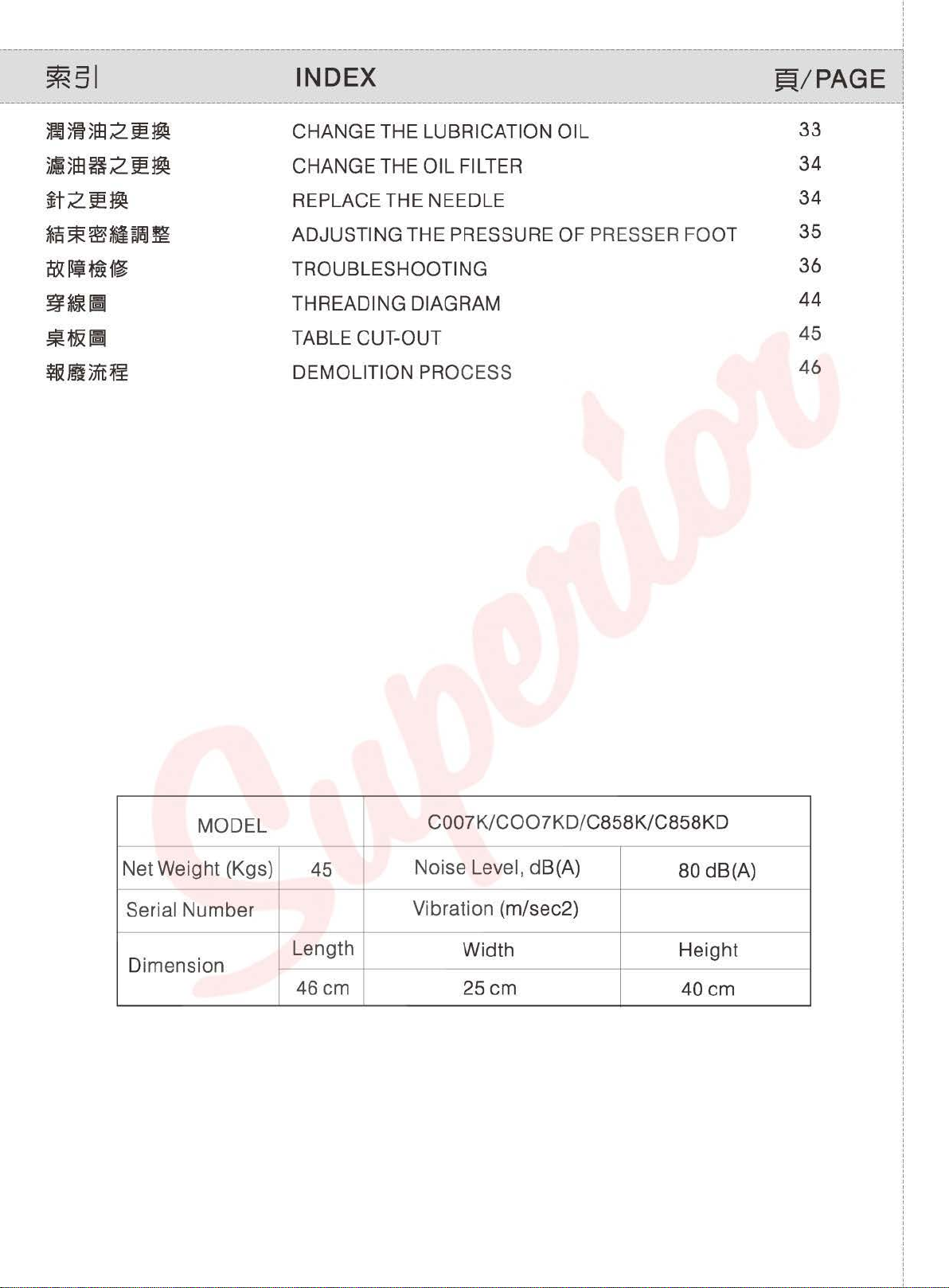
MODEL
C007K/C007KD/C858K/C858
-
Net Weight (Kgs)
45
Noise Level, dB(A)
-
Serial
Number
Length
Vibration (m/sec2)
Width He
Dimension
46cm
25cm
KD
80 dB(A)
ight
40cm
Page 6
'
'
'
'
'
I
t
~~
~
~
~ ~
-
ijg
--~~--~~--=~---=-~~--==~---
~EN
~~AL
SAFET~
I
~STR~CT~ONS
-~--~-~-
.!i!
=~m~~~H·~~~~m~•~~~g
·~•~*~,~-,~~@A~w~mm
0
§~~
~~~~~~H2~·~~~mfim~~§
~~2~111\
1.
1iMif'F.IfiJIJI
WiLa5lllm~H~.:.ftl12351~~
l')i~~~
0
0
o
Warning!
When using this machine, basic safety
Precautions should always be followed to
reduce the risk
personal injury, including the followings.
Read all these instructions before
operating this product and save these
instructions.
1 . Keep work area clean
Cluttered areas and benches invite
injuries.
2. Consider work area environment
Do not expose power to rain.
machine
Keep work area well lit.
Do not use power tools where there
to cause any fire or
tools in damp or wet locations.
of
fire, electric shock and
Do
not use
explosion.
is
risk
3.
-~··~·
~~gam~@~~~m@m~o
rg~ . ~AA!W~ . ~&rn}~~
4.
~f!Ji
1'~~IDJ~mMI~~~~i$'g~
5 .
••
1'~g~-~~!W~~g~~=
~~~~ffihl~~-~mogM~~~~§
a~fio
6.
'f'&GaJnJJJ:••
~1'~ffl~~~mhl~H·~
~~*W~~~
~~~ile
alua
99
••
~~~m~m
"~~~m•~~,s~~
o
C~
)
"
·~
=
~~~
3. Guard against electric shock
Avoid body contact with earthed or
grounded surfaces (e.g.
ranges refrigerators.)
4. Keep children away
Do not let visitors touch the tool or
extension code.
5. Dress properly
Do not wear loose clothing
they can be caugh
protecting hair covering to contain
hair.
6. Do not abuse the cord
Never carry the machine by cord or yank
it to disconnect it from the socket. Keep
the cord away from heat,
edges
..
in
Pipes, radiators,
or
jewelry,
mov ing parts. Wear
oil, and sharp
long
1.
••s•••
~~m~*~m~M~~~~~~~o~m
•~I~ffl~·W~fimm•·~~mam
~~~~H~*~~
0
7. Maintain machine with care
Follow instructions for lubr icat ion and
changing accessories.
periodically. If damaged, have it repaired
by an authorized service
-1 -
Inspect tool cord
facility.
Page 7
s.
E:PIIitaa••
~~~m~u~,m•~,~&~~~~~
0
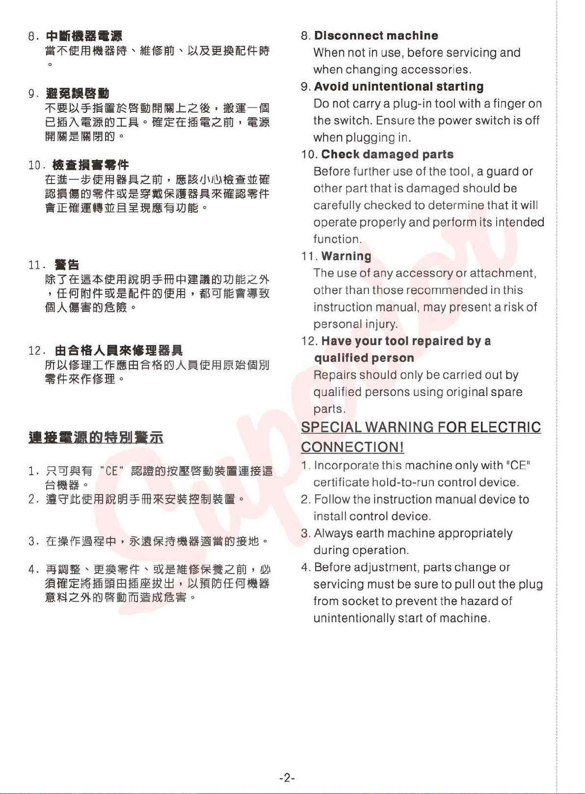
8. Disconnect machine
When not in use, before servicing and
when changing accessories.
9.
BJftiiiJIJ
~~~~m~~~~OO~L2~·-~-@
8~A~~~I~o~~tt~~2~·~~
00
!DL~
1"-l
~ ~
o
10 .•••••
tt51-~«EfflH~2~
~~~~~~~~g~~~HA*~~~~
·IE~~Qstrl§~JJfJ!I~JJJ~
11.
•a
~3tt·~~ffl~~~ffi~~~~JJJ~2~
·ff~~~~-~~~~ffl·E~~-~B
®LA.
~~~fBI!!
12.
El38fiA•*•JI8A
PJf
~
f~III
'!~*1'Ff~Jm
f'F
ftl:
1!1
S3
0
o
·
Hi~'J'll!H~'r~Ml~
iSm~
A~
o
tie
ffll*~
118U
9. Avoid unintentional starting
Do not carry a plug-in tool with a finger on
the switch. Ensure the power switch
is
when plugging in.
10. Check damaged parts
Before further use
of
the tool, a guard or
other part that is damaged should be
carefully checked to determine that it will
operate properly and perform its intended
function.
11. Warning
The use
other than those recommended in
of
any accessory or attachment,
th
is
instruction manual, may present a risk
personal injury.
12. Have your tool repaired by a
qualified person
Repairs should only be carried out by
qualified persons using original spare
off
of
1.
.R~Wl§
~~fto
2-~~~~ffl~~~ffi*~~~~~~o
4-A~~,~~~~,~~m•~•2~·®
~~~~~~EE-mW~·~M~ff~~H
:@~2~~~~ffij~~f8;~
"CE"
~m~~~~!JJ~Silm•
o
parts.
SPECIAL WARNING FOR ELECTRIC
CONNECTION!
1. Incorporate this machine only with 11CE
certificate hold-to-run control device.
2.
Follow the instruction manual device to
install control device.
3. Always earth machine appropriately
during operation.
4.
Before adjustment, parts change or
servicing must be sure to
to
from socket
prevent the hazard
unintentionally start
pull out the plug
of
machine.
11
of
-2-
Page 8

'
'
'
'
'
!
,
~~~~~m~~
------------
[
---------------------------------------------------------------------------
~-~-~~~H·~s~~~~H~
••=~m~~&~~~~ff·~~~
ff~~~m~~~H·~m~~s~~
~~mm~S·~~~~S~~ffl8o
~~M~~-~-m~&~EM~~~
0
0
0
2-~ffl~H~·~s~~ffl-~~~·
~~~*llllm~~flBffi
~~~~~~mOO~·~~~~M~
~gME!Jl1o
3-~~~~H~m~~~~~m~&~
~~~~~ffl~Ho
IDJ-~-0 lit~
IMPO~T;NT
For operating safely and getting the
best functions of this machine, you must
operate it
follow the instructions
and keep it at hand for future references.
We
are confident that you will enjoy this
machine as much as we enjoy
manufacturing it.
0
1.
Instead
when you use this machine,
pay attention to the basic safety
measures.
0
2.
Before using this machine, please
'
0
read this manual and all related
instructions.
this
3.
Before using this machine, please
ascertain that it conforms with safety
-
SAFE
correctly. Please read and
of
manual for future needs.
-
TY~NST~U~TION
of
this manual,
the following instructions,
In
addition, please keep
please
__
_
4-~~H~~-ff~·Mfi~~~~~
~~~8-iU~
~f'l=~1'fBl:7t~~
iJJo
5
Jl:~
~
H
{'J=
0
6-~s~~.u~m~~~~~~~m
0
(1)
~~t*i
~~~~
<
2)
~
~th
121ttM
•
~~~PJTi!tt~~~uml'
'~~-~}difi~
Jfl
S3
~ ~
®
ii'
~Ill~
2
~
1'1=
~
fl
'-~h
0
~~t , It~ , ~H& , ~~ , ~
'~ffi~~
o
'~S¥~~&~
'~&~flB!Jntrl
£8
4.
{S)
5.
0
6.
A
7.
standards and
country.
When the machine is ready for
operation,
must be ready. Operate this machine
without the specified safety devices is
not
allowed.
This machine must
properly trained operator.
For your own safety, we suggest you
wearing
Please turn off the power switch or
disconnect it for any one
circumstances of the
(1) When threading needle(s),
(2)
goggles.
adjusting thread Take-up(s),
thread guide(s), and/or
bobbin(s).
When replacing needles, presser
needle plates, feed dogs,
feet,
needle guards, horns, cloth
regulations
all the safety equipments
be
followings:
of
your
operated by a
of
the
replacing
-3-
guides and other parts or
accessories.
Page 9
(3)
*tE~I
(
4)
M
~0
fm
I
f'FP~
o
f'F
~
Pff
§.X
I
f'F
~
J5ff
1m
A
fit~
(3)
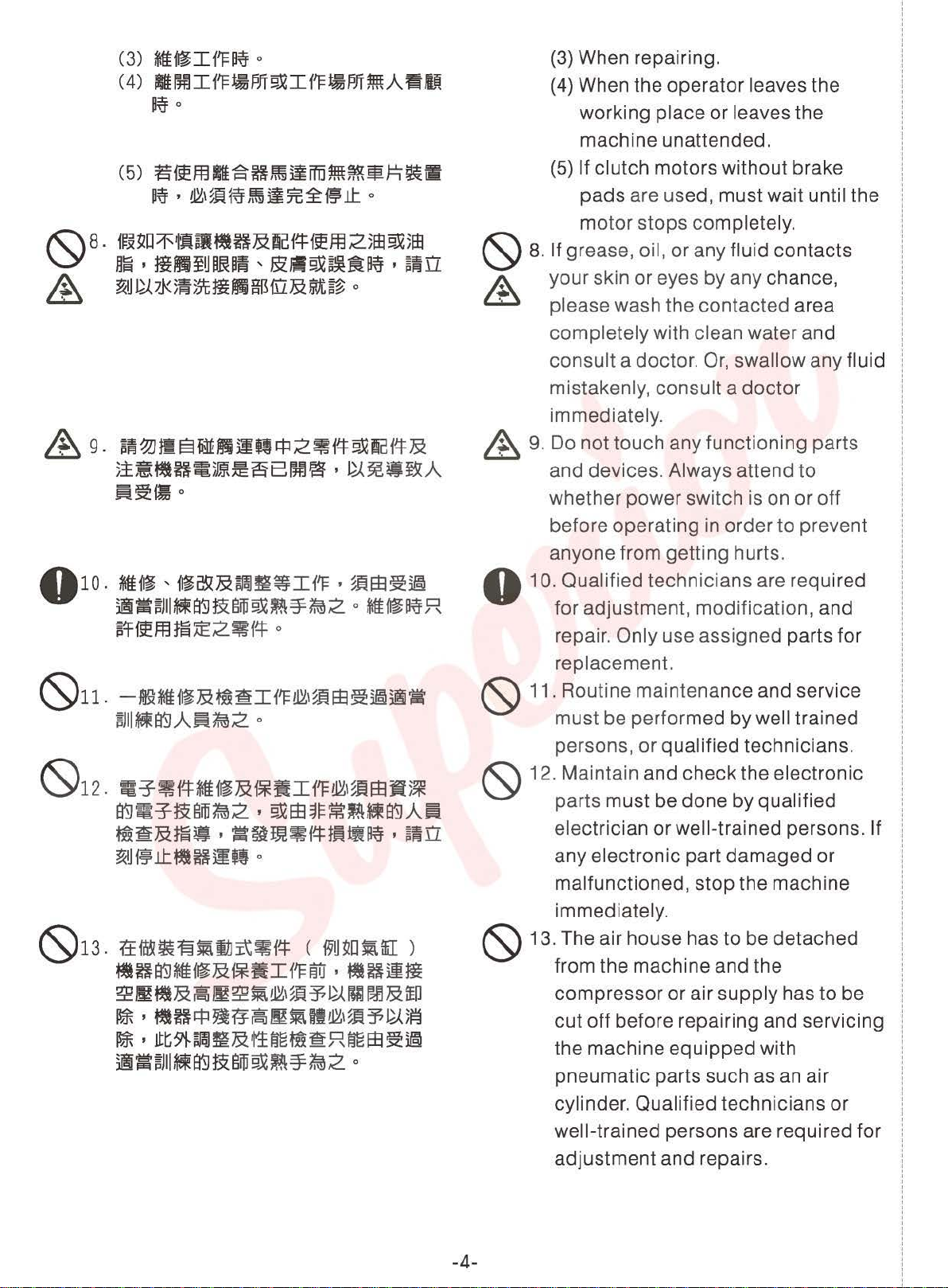
When repairing.
(4)
When the operator leaves the
working
machine unattended.
place
or
leaves the
&
(5)
~fiEffl.SHJi~ilffi.i~~mJ=1~fil
~ •
tl~M~
f..Hi~
i1
~ ~ ~
J.l:
o
(S)
&,
· please wash the
9-
~~~fe§~JS3mlllfl2~itf:9.Xftaitf:&
tt~~H~~~a8~®·~~~~A
~~fJ1o
&,
(5) If clutch motors without brake
pads are used, must wait until the
motor stops completely.
8.
If grease, oil,
your skin
completely with clean water and
consult a doctor.
mistakenly, consult a
immediately.
9.
Do not touch any functioning parts
and devices. Always attend
whether power switch is on
before operating in order
anyone from getting hurts.
or
any fluid contacts
or
eyes by any chance,
contacted
Or,
swallow any fluid
doctor
to
area
to
or
prevent
off
O 10. Qualified technicians are required
for adjustment, modification, and
(S)11.
(S)1
(S)13
-~*tEf~J.SHfi~If'F~,~~EE~~®
rull~e'9A~~2
2.
=~~itf:*tEi~&i*i'!If'F~I~fiE8~~
e'9~~§~~2·9.XEE$m~~e'9A~
•~&m~·=~~~~~~~~~n
~H~J.l:~ftiiq
.
tt~~~~jjji\~i~
~H
~~~&~~~~wm~~~~&w
II*
II*
~-~JII~ft9&gffi9J2~=¥~2
..
o
(S)
(S)
o
(
191J~D~ffii
e'9m.&i*·I~~·~H~m
•
~H!f:J~ff~~~~~~~~~~~5~
•
Jlt9i-~~&~tjgM~
.RtjgEE~~
o
)
(S)
repair.
replacement.
11. Routine maintenance and service
must
persons,
12. Maintain and
parts must be done by qualified
electrician
any electronic part
malfunctioned, stop the machine
immediately.
13. The air house has to be detached
from the machine and the
compressor or air
cut
the machine equipped with
pneumatic parts such as an air
Only use assigned parts for
be performed
or
qualified technicians.
check
or
well-trained persons. If
off
before repairing and servicing
by
well trained
the electronic
damaged
supply
has
or
to
be
cylinder. Qualified technicians or
well-trained persons are required for
adjustment and repairs.
-4-
Page 10

015.
~1f"B~IEm~i'l=~&~~~~
"~~®~m~k·~B~~H~~~
®
£rSJ
II~
""F
tl
i'F
0 14.
,
o
0
To
ensure the best performance,
periodically clean the machine is
necessary.
15.
In
order to operate properly and
reduce the noise, please
machine flat and level on the
ground. Avoid operating the
place
to
the
(S)
16 . 31
A
18
sewing machine
surrounding.
l=IBI
tit
e'5J
~)mUm
RR~~H~Bk·§~illl®~~Hm
tttH~2RI3~k
m1
•
sltHE
~
::f
~
gili
o
A 18. Any
°
1~r&9.X!l~~H~I~~~~~~jlJE&
~-·~~~DfiBS'5J~~-~9.X~~
~BPJT51~1~!12Jl
o
16. Select a proper power
it
by
install
connect
grounded
17. This machine can only be used tor
the designed purpose.
of this machine are not allowed.
modification
made
conformed
standards and regulations.
Precaution is necessary.
responsibility will our
for
modification
on this machine
damages
an electrician. Please
the power plug
receptacle.
with the safety
at
a noisy
plug
to
a
Other uses
or
conversion
must
No
company
caused
or
conversion of this
by
any
and
be
take
A O)
&
C2)
machine without permission.
19.
Two
safety warning signs are
applied as warning signs:
& (1) For the safety
~tii'F~9.X~mA~2~~®:
lln
f
~~J~~ftltl2fB~1i
~n~~~Hiffijl~ft~29i-~
~JJm~umflim2~itt=
I
~~
I
~1'
o
service persons, please don't
open the cover of any electronic
control boxes
devices and don't touch any
components
electrical
& (2) Always keep in mind:
~~~~~gu)±~~rn
a.
*~~1'DJH~l1J9i-~
~~9.X~~~citt:~
~i'F I ~~?5~A~~{I
·
~}~1~
I
imfj~ft
0
a.
Please never operate this
machine without
finger guard
device
of
operators and
of
motor
inside
shock
to
hazards.
or
any safety
avoid physical injury.
or
to
avoid
outer
other
cover,
-5-
Page 11
&
&
b.
~s~~~~u•a:.
i'IQ!f:l '
,
~iilfl'¥fii
~IFf'DJJ.&fi:f:E®!W~
~~.AiiB~il
c.
:1mrrrm~)mtf#l!DH~9.X~HB
1±
i'l"
1±
jf
if:l
,
~ffil~
if:l
'
B'5J
1'
15
~~)JJ~.A~~11
'
:
Jt~9J.~$ff!Ha
o the machine is
~
::f
OJ~~~
§.X
jf
~
s~u
g~~:&1X"~
'
~~
ffil
~
~
~ ~ ~
o
9J.
§
&
&
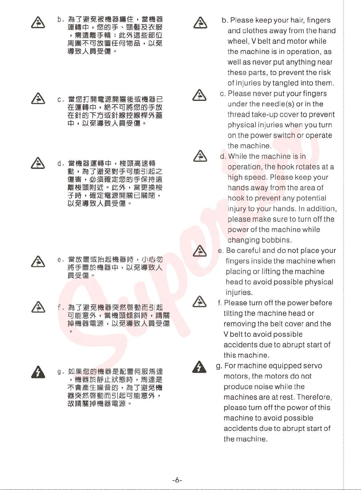
b.
Please keep your hair, fingers
and clothes away from the hand
wheel, V belt and motor while
in
operation, as
well as never put anything near
these parts, to prevent the risk
of
injuries by tangled into them.
c.
Please never put your fingers
under the needle(s) or in the
thread take-up cover to prevent
physical injuries when you turn
on the power switch or operate
the machine.
~
&
&
d.
S~H~Qif:l
i1J
'~1'it¥~~'¥DJ~~
11~ , mM~lil~1mffil'¥f*~~
~~~~3IT 0 Jt~9J.
.:y
~ '
lil
~~?JI~A~~fl
~ ~
)ml
'
~~~~tt
Iie2
'
~!@~fi
f#l!D181D1
o
r-l]
'
&
e.
&
tit~~§.Xt-gte~H~
~~-~~Hif:l·~~-~.A
~~~0
f.
~1'Yi¥~~H~~~!tlffii~lie
0]~~91-' ~~~1tff~~ltij
~~H~)f* , ~~~~.A~~iJJ
0
'
Jj\lll,\~
'
~~g
&
d. While the machine is in
operation, the hook rotates at a
high speed. Please keep your
hands away from the area
hook to prevent any potential
injury to your hands. In addition,
please make sure to turn off the
of
power
changing bobbins.
e.
Be
careful and
fingers inside the machine when
placing or lifting the machine
head to avoid possible physical
injuries.
f.
Please turn off the power before
tilting the machine head or
removing the belt cover and the
V belt to avoid possible
the machine while
do
not place your
of
g. For machine equipped servo
A
g.
!lD~1mffil~H~IC.~f~m~~ji
•
~H~~.Lt}ltfm~
1'fl~~~~ffil·1.m1'im~~
H~~@iJ.Jffii51ieDJ~~9J.
~~~!Ulf~~ft~)mt
'
,~ji~
0
,
-6-
A
accidents due to abrupt start
this machine.
motors, the motors
produce noise while the
machines are at rest. Therefore,
please turn off the power of this
machine to avoid possible
accidents due to abrupt start
the machine.
do
not
of
of
Page 12

h.
Never operate the sewing
machine after the ground wire is
removed to avoid electrical
shock hazards.
i.
Please turn the power switch off
before connecting or
disconnecting the power plug to
prevent possible accidents due
to electric shock or damaged
electronic components.
•~~~~H9~&m~.~~~~~~
~~:
l.~~~~S~H··~~-~~Hm
fFiW
•
~~li®~)JIHIH
o
Please confirm the
malfunction or damage to this machine.
0
1.
After installing the machine, and
before the first operation, please
clean it completely.
0
2.
Clean all dust and overflowed oil
during transportation.
0
3.
Confirm that the voltage and the
phase (single or 3 phase) of motor are
set correctly.
e>
4.
Confirm that the power plug is
correctly connected to the power
supply.
{S)
5.
Never use the machine when the local
voltage type is different from the
marked voltage
attached
on
followings to avoid
on
the nametag
the machine.
0
6.
Confirm that the rotating direction of
the machine
A warning:
Before doing any operation or any
adjustment described later
manual, please turn the power off to
prevent accidents caused by abrupt
start of the sewing machine.
-7-
pulley is correct.
in
this
Page 13
--------~------------------------------------------------------------------------------------------
I
I
I
I
I
1
~~~~-
---------------------------------------------------------------------------!
·•~m~~-~~~~~~mk~~m·w
m~m~•~~~~-~~~•~•~m~
0
.....
:tfi3fiU5~JIDiftWII
T
cu::hing
p-esent
T
l.JT1
before
~~'tUJ..Jls:t41
aeos
C<J'l reslit:
off
main
opening
wi'"'lere
switrn
this
hig, vdtages
in
severe injuy.
01d
wait
o:JVer.
ae
5 rrirutes
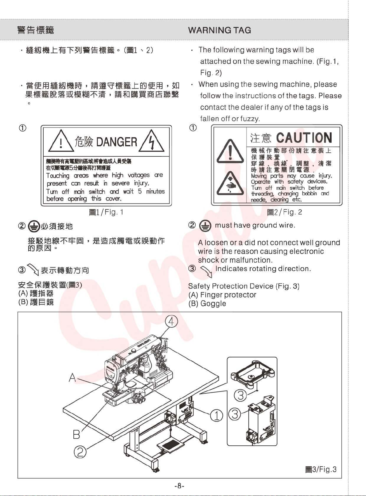
WARNING TAG j
The following warning
attached on the sewing machine. (Fig.1,
2)
Fig.
When using the sewing machine, please
follow
contact
fallen
the instructions
the
dealer
off
or fuzzy.
if
tags
of
any
will be
the
tags. Please
of
the
tags
is
CD
&
A\
~!~CAUTIO
•
f&
fF
lb
$
i~ ~ ~
i~HI~W
~-.tA-·.~g.~~
~-~tUM•··
Movirg
Operate
T
itYeoc:rrlQ,
neede, dealirg etc.
llll
off
pais
may
with
safety devices.
rrdn
chalgirg
COJSe injuy.
switch
bcl:X:>in
• ~
before
CJ1d
N
l:
I
I
!
i
I
I
I
I
I
I
I
!
I
I
I
I
I
I
I
I
I
!
i
!
I
I
I
I
I
I;Jl/Fig
. 1
~@~'~HOt!!
-~~~~~~~-~~~~~~~~
a'i)~~o
@
~
~iJ\ft~J:J!OJ
~~1*~~ia(IIJ3)
(A)
~t~H
cs)~§m
~
@
loosen
A
must
have
or a did
wire is the reason
@
shock
~
or
malfunction.
Indicates rotating direction.
j;!2/Fig
ground
not
connect
causing
. 2
wire.
electronic
Safety Protection Device (Fig. 3)
(A)
(B)
Finger
Goggle
protector
well
ground
-8-
III3/Fig.3
Page 14
I
!
I
I
~------------------------------------------------
1
~~t,..,...,4>1iiiil~
t
p:sz5J!
!-----------------------------------------------------------------------------
:
:
~s~~2~R~~-~~•Mm·•~~~
!
1ftf2~ff~~
i
I
~
.±:.
~
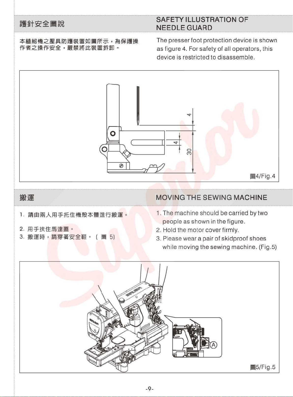
p}lj NEEDLE GUARD
'
ii~~Jtt~fH!FfED
o
SAFETY ILLUSTRATION
The presser foot protection device is shown
4.
as figure
For safety
device is restricted to disassemble.
i
!
i
'
i
:
!
I
I
I
I
I
~-----------------------------------~--------------------------------------------
OF
of
all operators, this
ffij4/Fig .4
1
!iii
!-
1
'
1
l.~m~Am~ffitt~~~-~5~~
!
2. m
~~1±~1111
3.
~~~ ' i~g-~~ti
o
0
( IIi 5)
0
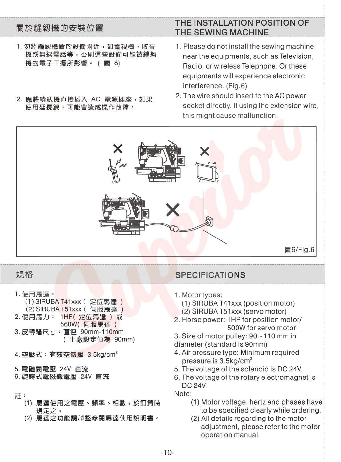
MOVING
1.
The machine should be carried by two
people
2.
Hold the motor cover firmly.
3.
Please wear a pair of skid
THE
as
shown
SEWING MACHINE
in
the figure.
proof
shoes
while moving the sewing machine. (Fig.5)
-9-
[;5/Fig.5
Page 15
:
I
I
I
·---------~-----~--------~------------------------------------------------------------~------------1
IIF~~~Y.~atlir.Jr+t~r.;~
ltn~JJJ'm~v~u:~~3t~LU.I!§!.
THE INSTALLATION POSITION OF l
THE SEWING MACHINE :
I
------------------------------------------------------1
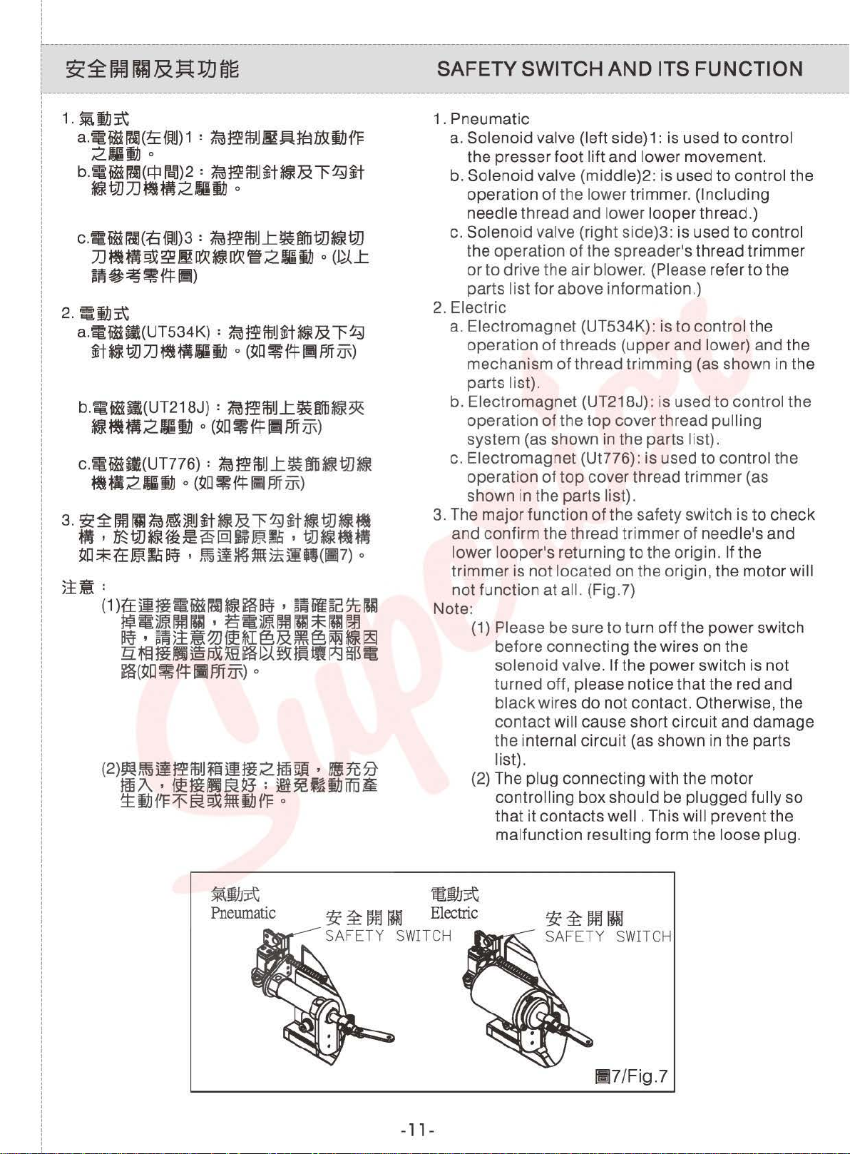
1.
~~-~~·~~iimllnHli
~D~~~~-·~~~®W®~~-·~
fta5J
~-:f:rti?Jf~B
2.
HI~M~~®HHm.i\
~ffl~~Si · ~~fl~/JXtlf'Fi!&P~
•
~D~tJ!~,
o (
II
6)
AC
~5mtHilm
!&~
•
~D~
o
X
v#
\"\\\
1. Please
do
not install the sewing machine !
near the equipments, such as Television, :
Radio,
or
wireless Telephone. Or these I
equipments will experience electronic
interference. (Fig.6)
2.
The wire should insert
to
the AC power
socket directly. If using the extension wire,
this
might
cause malfunction.
X
'0,
!
I
I
i
!
i
!
X
----------------------------------------------------------------------------1
~Jim
r
l.
fieffl~ij:
(1)
SIRUBA
(2)
SIRUBA
2~
~fflJiffi:t.J
3. BlmfniR'tt =
5.
~fiH!al
6.1itEfii\!ifiHIHi~
~~
T41xxx
T51xxx
: 1
560W(
24V
(
AE[L~il
(
~"~~~il
HP(
AEruJlffiil
~IR~il
@{~
(
90mm-110mm
l±llHWAEfl~
) D
)
90mm)
@;nt
24V
®;nt
)
)
sPECIFICATioNs
1. Motor types:
(1)
SIRUBA T41xxx (position motor)
(2) SIRUBA
2. Horse power: 1
3.
Size of
diameter (standard is 90mm)
4.
Air pressure type: Minimum required
pressure is 3.5kg/cm
5.
The voltage of the solenoid is DC
6.
The voltage
DC
Note: !
-1 0-
motor
24V.
(1)
Motor voltage, hertz and phases have !
to
(2)
All details regarding
adjustment, please refer
operation manual. i
III6/Fig.6 I
- :
T51
xxx (servo motor)
HP
for position
500W for servo
pulley:
of
the rotary electromagnet is 1
90~11
2
be specified clearly while ordering. i
motor/
motor
0 mm in
to
the
to
24V.
motor
the
motor
I
I
I
I
I
i
i
1
I
I
I
I
!
i
!
I
I
I
:
I
I
I
I
i
!
!
!
i
!
I
I
Page 16
i
:
:
'
'
r------------------------------------------------
1
f
~~fm!U1&~JJJfjg
.-----------------------------------------------------------------------------
'
'
:
'
'
!
i
'
2.
~11Ji\
a:~fiHS(UT534K)
~t
~
w
7J
~
b.~tiHS(UT218J)
~~-2-!JJ o (~O~f-!:IIPffiJ\)
C.'~{iHJI(UT776)
~tfij21ii1J
3.
~~~~~f.m~)~
:
f.m~~J~t~&l'~
mfi
I1J
o
(~o
~
r-t
111
?ff
iJ\)
:
f.m~ffiU.t.~mli~
:
~~ffiUL.~mti~tl.J~
o
(
~D~f~
IJ
~t~&l'~~t~tlJ~~
j;iPJfiJ\)
~
~·~tm~-~~@~~~·tm~~~
~D*tt~,.S~
):£~:
( 1
)?'£
3~Hi
~~)m!!mll
P~ • ~~5±~~tif*I§&~§i~IHi~
IJ.ffimfiH§~~~~~~il~aB=
~(~O~f~I1PffiJ\)
•
Jiffii¥~~5~~Q(IIJ7)
~
fiH
itJI
~
~
~ • ~~
'~~)m!~ll*llr-!1
o
lii~a%
o
rDJ
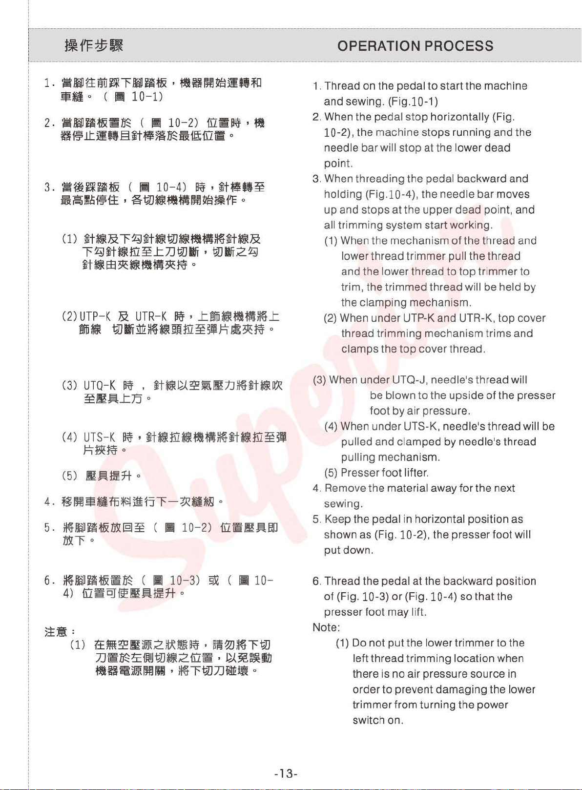
SAFETY SWITCH AND ITS FUNCTION
1. Pneumatic
a.
Solenoid valve (left side)1: is used to control
the presser foot
b.
Solenoid valve (middle)2:
operation of the lower trimmer. (Including
needle
thread and lower looper thread.)
c. Solenoid valve (right side)3: is used to control
the operation of the spreader's thread trimmer
or to drive the air blower. (Please refer
parts
list for above information.)
2.
Electric
a. Electromagnet (UT534K}: is to control the
operation of threads (upper and
mechanism of thread trimming (as shown
parts list).
b. Electromagnet (UT218J):
operation
of
system (as shown
c. Electromagnet (Ut776):
operation of top cover thread trimmer (as
shown
3.
The major function of the safety switch is to check
in
the parts list).
and confirm the thread trimmer of
lower looper's returning to the origin. If the
trimmer is not
not function at all. (Fig.?)
Note:
(1)
Please be sure to turn
before connecting the wires on the
solenoid valve. If the power switch is not
turned
black wires
contact
the internal circuit (as shown
list).
(2)
The plug connecting with the motor
controlling box should be plugged fully so
that it contacts well . This will prevent the
malfunction resulting form the loose plug.
lift
and lower movement.
is
used to control the
to
the
lower) and the
in
is
used
to
control the
the
top
cover thread pulling
in
the parts list).
is
used to control the
need le's and
located on the origin, the motor will
off
the power switch
off, please notice that the red and
do
not contact. Otherwise, the
will cause short circuit and damage
in
the parts
the
~IE~
Pneumatic
3i:
~
00
SAFETY
IHl
SWITCH
-
11
~111~
Electric
-
!fi~OOIUJ
SAFETY
SWITCH
!117/Fig.?
Page 17

:
I
I
I
·---------~-----~--------~-----------------------------------------------------------~-----------1
¢r.;ga--,
N::Lll~itx:::..3i~
-----------------------------------------------------------1
,..,._,~EfB§!%1"
......
P1cJ~
INSTALLATION AND ADJUSTMENT l
OF
SYNCHRONIZER :
1.
Press the hidden synchronizer into the long
groove of the machine head, and then tighten
the screw (3). (Fig.8)
2.
Before connecting each wire
or
plug, please
check that all the electric switches are turned
off.
3.
The mark
shorter marking line
(1)
should be aligned with the
(3)
on the hand pulley (2)
I
I
!
:
!
I
I
I
I
i
!
i
!
when the needle bar is at its top dead point.
(Fig.9)
~8/Fig.8
!;9/Fig
.9
-12-
Page 18
2.
~!iiDUH&~~
H@.lt.jif!§~t~m~~ift[lf!!
3 •
~~~~f&
ii~!~f~i±
(1)
~t~&l'~~t~WJ~~~~~t~&
""f~~t~ID~J:7JWJIIT
~t~S3~~~~JB~~
<2)
uTP-K & uTR
~~
(
Ill
10
-2)
[I~~ I ~
o
(
11!1
10-4)
I
aWJ~•m~m~tHlf'F
-K
WJIIT~~~~ffi~~J=1~~~
lfi¥
I
~t~tt~
o
I
WJIIT2~
o
~R¥ I J:mti~*lm~
J:
0
1.
Thread on the pedal to start the machine
(F
pedal
ig.10-1)
stop
horizontally (Fig.
and sewing.
2. When the
10-2), the machine stops running and the
needle
bar
will stop at the lower dead
point.
3. When threading the
pedal backward and
holding (Fig.10-4), the needle bar moves
up
and stops at the
upper
dead point, and
all trimming system start working.
of
(1) When the mechanism
the thread and
lower thread trimmer pull the thread
and the
trim, the trimmed thread
lower thread to
top
trimmer to
will be held
the clamping mechanism.
(2)
When under UTP-K and UTR-K, top cover
thread tri
clamps the
mm
ing mechanism trims and
top
cover thread.
by
(3)
UTQ-
K
lfi¥
•
~t~~~i\111J~~t~~
~~~J:JJ
(4)
U
TS-K
h~~o
C5)
~~m7t
4.
~f7~H~fJffi~ji~jl'-~il~~
5.
~liill~~m§l~
o
~,
~t~ffi~*l~~*t~ffi~~
o
o
c • 10-2)
fi1lfi~~J:m
fRl'o
6.
~IIID~~f&iii~
4)
fi1~CJ~~~m7t
3±~:
Cl)
?±~~~)~2~~lWi I a~~H~l'tJJ
7J~~~ffi~i!JJ~2[l~
~H
C
II
1 0-3)
o
i!)~ml!Bl
,
~""fi?IJ7JM1!!~
9.X
(
II
I
~~~IJJ
o
10-
(3) When under UTQ-J,
needle's thread will
be blown to the upside of the presser
foot by air pressure.
(4) When under UTS-K,
needle's thread will be
pulled and clamped by needle's thread
pulling mechanism.
(5)
Presser foot lifter.
4.
Remove the material away for the next
sewing.
5. Keep the pedal in horizontal position as
shown
put
6. Thread the
of
presser foot may
as
(Fig.
l0-2),
the presser foot will
down .
pedal at the backward position
(Fig. 1 0-3) or (Fig. 1 0-4) so that the
lift.
Note:
(1)
Do not put the lower trimmer to the
left thread trimming location when
there is no air pressure source in
order to prevent damaging the
lower
trimmer from turning the power
switch on.
-13-
Page 19

C2)
~~rc
im~2~~tfm~·m~~l't.JJ7J~~
~ff!Ut.JJ~2fi1~
~OOIOJ•~l't.JJ7J~1fo
C3)
~¥11'75*1.&11UlUiffi~~
~ttf'F§JtJ.Jt.JJ~~m
CUTR-K , UTS-K)
·
~~~tJJ~H~
o
?±mt
•
~~
(2)
Do
not
put the lower trimmer to the left
thread trimming location when the
electromagnet types (UTR-K, UTS-K) are
disconnected
should be turned on and the lower
trimmer should be damaged.
(3}
When there
presser foot, do not operate the auto
trimming system.
lest the power switch
is
no fabric under the
4
3
2
1
~~~[le/
1.
Wi~
PEDAL POSITIONS
(!m~tH~*i)
Press forward (start sewing)
2.
t:P~
c~m~
l'm)
Horizontal (presser
3.
~*1m
C!m
~~H)
Press halfbackward (presser
4
.~~
(§lftli?JJ&R~~)
foot
down)
foot
lifts}
Press backward (automatic thread trimming)
!Ill O/Fig.1 0
-14-
Page 20

:
I
I
I
·---------~-----~--------~------------------~----------~-----------------------------~-----------1
I
--------------
-ag~{tJ::g~
------------------------------
(1)~**~
(2)
~~h
(3)
~~
C4)
~ifi!Jm
C5)
5ftlm
(6)
!TI~~~~~~
(7)
~fHB
(8)
MR~
~~i*~~~
(9)
~~~~~~~
00)
~~H
NAMES
OF
MAJOR PARTS i
(1) Thread Guide Box
(2) Thread Guide
(3) Presser Foot
(4)
Control Box
(5)
Oil Windows
(6) Thread Tension Adjusting
(7) Pulley
(8) Thread Stand
Safety Protection Device
(9) Thread Take-up
(1
0) Finger Guard
Cover
-------1
Set
I
!
:
!
I
I
I
I
i
!
i
!
-15-
lj11/Fig.11
Page 21

i
:
:
'
'
r
-;m~~
!-----------------------------------------------------------------------------
'
'
:
'
'
i
~~~&~lm~oo
1.~5m&5.J'~~~iJ\
'
----------------
007
C
858
K 0 - W 1 2 2 - 2 4 0 I C H
T~-;~E~C~I~TI~N
Specifications
1.Description of the machine name
of
machine category
OF
T~E
MODE~
--
~
CD~m~~gu
C=~i\
®~iJ\*t=l9i-fii:&~2~5.J'fiK~
mG'
@~m7JD
®w~
~~3Z:~B;H~~9U~DC007K/C858K
..t.sz.m Clfil1
~t*
~
fqJ
H~
=
tj\J~ffi
it
0
2)
~~
'
o
~
~~
EEF~
o
6¥
CD
represents the type of the machine:
C=
®represents
appearances that are arranged from
letter
@represents
@shows
stitchery or not.
W=
~
Three needles cylinder bed
chainstitch machine
the improved machine
F.
Ex:C007K/C858K.
a small servo motor added.
whether having upper cross
have upper cross stitchery (Fig.12)
!1112/Fig.12
U
Umt..tsz.~
CIU3)
-16-
=Without
upper cross stitchery (Fig.13)
.13/Fig.13
Page 22

@§fi-~i\:
12
=
-~mm
13
=
~
l'
M
15
=
~-, ~~• , 173
1$~1Ml:1MM
16
=
-~~ffi~2§fif.J
22
=
!Jmijl~§~f'F~
32
=
§effi~f'F~
51
=
l:
~i\f~~tM
52
=
l:
1E il
f~~~
53
=
Ji~:q:zm~~~_t~mm
_t
mmm
a~mu1!W
@is stitch ing type:
12=
general seaming
13=
bottom hemming
15=
elastic tape feeding for cotton f
such as underwear, and tights pants
16=
general seaming for normal thick
materials
22= tape binding
32= seam covering (decorative st itching)
51
= elastic tape feeding, upper feeding
type
52=
elastic or lace seaming
53=
elastic tape feed seaming
in
hooped
abr
ic
54
=
l'~i\f~~~_t~m
61
=
~®moma~
71
=
!til*l
72
=
711M*If'F
81
=
~l'~
82
=
~~~
92
=
~tmgg~tmm
®
•m~~~~2~~m~~~m~
f.f~)
1.~*11W~R¥
1$
(IIllO)
~
tt)
~
Pm~WJ)J
1ML.1Mi1*1Pm~i1J)J
,
~t~~~~,
9.X
*IBM
lEe
(
m
15~t
I
D"1
=
-~m~(mt
!?A
_t)
aey
~
ffl
o
type lockstitch
54=
elastic tape feeding, lower feeding
type
61
= belt
71
= double chain stitch
72=
81
=bottom
82=
92=
@means the shape of the
tongue , whose function is to knot. (Fig.1 0)
1 = While sewing, the stitches are closer
2 = Standard stitch
3 = The stitches
loop
seaming
pocket
elastic tape feeding with left trimmer
four needles chain seaming
to each other. For normal threads
without stretch, or
stitches/in or above).
stitches/in.).
lining seaming
hemming with left trimmer
needle plate
closer stitches (15
length
length is wider. For
(11 ~ 14
stretch threads or
(1
0 stitches/i
-1 7-
long stitch length.
n)
Page 23

[7'
1
Q)~m~~t~fl
2~2~t*
3~3~t*
4~4~t*
([IH4)
[7
[7
2
3
Q)
is the number of stitches. (Fig.14)
2=
2 needles sewing machine
3=
3 needles sewing machine
4=
4 needles sewing machine
1114/ Fig.14
@means
between the
(Fig.15)
-
-18-
!1!15/
the needle width (the distance
left and the right stitch.
!;16/
Fig.15
Fig.16
Page 24

3.2mm,4.0mm
4.8mm•5.6mm
6.4mm
3.2mm ' 4.0mm
4.8mm ' 5.6mm
6.4mm
@Qi!IJJfl~
2.m~~§(~1)
e
~
L
M
H
:
~DCH,
For
For
medium-weight
For heavy-weight materials
~~
~Ji
ij!~ffi~
ij!*IQ~(R.
Max.
Sewing materials
•
P.
M)
sewing
rotational
CO,
CZ
...
~~
m~
Application
m~5!ffi~
light-weight
ffl~q:J~ffi~
m~~ffi~
materials
materials
~
5!ffi~
--t::
speed
ight materiT edium weight
4000 5000
® is
2. Purpose
gJUlifQ~
Sewino rotational
~1/Table
3 s
C007K/C007KD/C858K/C858KD-XX
CZ, etc.
4500
4500
6000
1
.
~pec1
I
supportive
(Table 1)
models,
R.P.M
speed
'f
1cat1on
q:J8ffi~
mater~
such
~~e
Max. Stitch length
1-4.23
I
1-4.23
-4.23
1
)jffi~
Heavy
_material
as CH, CQ,
(mm)
-
weight
-
4500
~~Noise
~~e
~t"~j~
fsEffl~
~<'l!!tt.J
~~~7+
~<'l
~~~~~
mil
ti~~~R
~~R
7JQ5E875i\
w~m5m
Jlffijl
~ifiU~~
Stitch Length
Needle
Needle
Presser foot
~
Presser foot
Weight
"1
"1
Table
Lubricat
oil
~~-ii.J
Machine
Motor
Control
bar
DBX
Presser
Feed
dog
Machine
specification
ion
head
circuit
stroke
1-DPX5
pressu
foot
height
height
head
driving
r--
-
29mm
SCHMETZ
~
4-5KGS
-+
0.8mm
tl~
605mmx
fiJ!~lfutf:l
Output
80dB/4000
4.23mm
T
UY128GAS#70
31mm
ORGAN UY128GAS #1 0
I
5mm
0]~~11~~
Head:
~
1200mm
~~!§!
~1#2.~ffl5W
i§[;!i~j)j~a
power
45kgf
Long
ii.JJJQ
400W
0/2HP)
400W (1/2HP) Max.
ffi/~ffi
Adjustable
1mm
~mum
460mm
5EB
x
Automatic
SIRUBA sewing
Directly driving device.
3-phase/
R.PM
I
5-7KGS
presser
I
Control
~
Height
605mmx1070mm
lubrication
~::*:mtf:l
Output
Single-phase
box=
400mm
machine
50
0W
35mm
foot
1.
system
(3/
500W (3/4HP)
-
2mm
4.1kgf
oil
4HP)
fsEffl
~~
~
fiiU~
Ill
Solenoid
Power
J.i
i1.J
~
driving
5~
power
ffi/~ffi
~2/Table
-
19-
3-phase/
2
Single-phase
DC-30V
Page 25

i
:
:
'
I
~~~~~
,
IIJII.I/J,~m~=~.!Jj8>z::~
!---------------------------------------
'
'
:
1.
'
'
!
i
'
tili
1'11\1
~ ~
~~f'F~
Cl)fifffl
..tl'=l=li\~i*Bffl~tiH§
~WJ~o
~ 0 ~+..:.,
~
Ti5
-------
.±.,.:r.,trs;',~~
, M
PoRT
OF
THIS
ANT-sAFE-Tv
MACHINE
1 N
sTR
1 .Transportation
(1) The machine packed with two
up
and
lower-
covers that made
ucTI
piece-
of
oN
s
--
C2)
m.A*ffijH'3
C3)
m=¥mms.x=Am~=¥tt:ti11~~
2.
~t:f{'F*
Cl)
~H1'11Effl
°
P~ • ffil=f.H~.O
~~~Jt~
J:o
(2)
il~i~G~~~
0
3.
{'F*Ifl
~H1'~H~~40t~l:~~Miff
0
4.
II%
~~51~~l'IIIJ\W~~IW
(1)
I{'F~~~fB!ln~
C
2)
~
~H
~
tt
im
i~fli~t
(3)
~tt~ffi~~~1~~~DD'J'l~\
C4)
1'~re=¥1~mtt~tw~~ffi~~"
~2rdl
0
0
45
f'F
~
~1~*~
OC~l:~~)[fg
o
o
~1'~
o
o
~
expanded Polystyrene
(2)
Put the machine into a carton.
(3)
Use a cart
or
by
two men's hands
to
protect it.
move it.
2.Storage
(1) The machine must use duster cover
cover it when it
did
not work.
(2) Do not storage the machine over 45
3.Working
40
The machine doesn't work over
OC
4.Warning
Pay attention
to
the following warning
advices:
(1)
Working area is dangerous.
(2) Never touch the needle
if
the machine
is still running.
(3) Be careful if you infeed fabric.
(4) Do not insert your finger between
needle and roller for transportation on
fabric.
to
to
OC
tt~li~-%~7J\2JE~~;1~
(1)
~~!J.J{'F$53'
~0
(2)
g~
'~~ '~~
~IU]
00~)~
'
~~)i~~l:i*~~
0
0
'~)jl~
'~~51
Pay attention
Movable parts must
(1)
to
the warning sticker.
guard when you operate.
(2)
Turn
off
the power during adjusting,
threading,
bobbin-changing
needle-cleaning.
be
enclosed with
and
-20-
Page 26

--------~---------~------------------------------------------------------------------------------------
INSTALLATION
:
I
I
I
:
r::::\
~~
al
\..Y Machi
A
~~~~~~~~i§Jia~B3~.A~51Hj~B~c~
A
~ 3f~Hf!
ne
~JII
~
15l
WI
A~*~~
installation should only be carried out by qualified technician.
)!~CAUTION
*i
tJl
~
o
o
V Contact your dealer or a qualified electrician for any electrical work that may need
be done.
A
~~~m45~JT,
~!&I1'F~~~wEE~.A~J:*~f.iX
o
V The sewing machine weighs 45kg. The installation should be carried out by two or
more people.
r::::\
\..Y Do not connect the power cord until installation is complete. The machine may
A
~
tt~!&~f.iXM
operate
if
~~~RW1¥1Jl'~JreB~,
ffiJ5~m
Use both hands to hold the machine head when tilting
original position.
heavy to hold, and may cause human physical injuries.
,
ffiJ~~~~
'
~~1'~ilm~5mt
the treadle is depressed by mistake, which could result in injury.
~~m~~iint~1'F,
0
If only using one hand, the weight
'
~D~~~~fJJ~!Dl
~~tl1'F~O.Jtrei!~m~~~m•~m
of
'
*itJl~fJJ{'Fl\f~~~{g
it
back or returning it to its
the machine head may be too
to
o
1.
1.
BX~-f:iJTMt~~~lli&~ftt*H'811?Jf9U2Jic
1tt
'
BX~~~WJ~~-~ , ~~
2.
~312f3[0J~lm~t175[0J,
m=¥~[0J~~l' 2 i}7.1~ili,
iEe.5[
,
~~&:m~~~~t~..t
o
&:M2~~M~
!5J~~'J~~
o (
11
17
,
1s1
Before installing machine, please refer
to table cut-out drawing, and the
necessary attachment as enclosed,
fix cushion base, thread stand.
2.
Be sure that the motor turning direction
is clockwise, and the motor
can be pressed with finger inward about
2cm. For safety reason, please fasten
the
belt cover. (Fig .1
7,
18)
be
lt
tens ion
to
-21-
!;17
/Fig.17
Page 27

3.
Regarding machine
speed
!ll18/Fig.18
and
motor
pulley diameter, please refer
'+~
/.:I:
,'tt'-
:
l.
fiEFf.IWi'~Hft:fJJ-®IF.IiiBlilJH!'iJ~&~lt
it2
(
~0~
80%
3)
•
Mz~iiifilEtii~Jiffiil~rnBR
0
1t
Remarks:
1. During the first month of using
machine, the maximum rotational
shouldn't exceed 80%
of
the speed
listed in Table1. Make sure to
2.
~~~MMSJ
45mm o
correct
2.
The standard thickness
size of
motor
pulley.
of
45mm.
Note:
BltMeHUR~
Belt size
depend
on
motor
MOTOR PULLEY SIZE BltMR"tr
-~
R.PM
60HZ
50HZ
to
Table
the
choose
Table is
type .
BELT SI
3.
speed
the
about
ZE
6000
5500
5000
4500
4000
105
95 115
85
80
70
I
~3/Table
3
125
105
95
85
-22-
36"
t
35"
~
34"
Page 28

:
I
I
I
-------------------------------------------------~-----------------------------------------1
~~jl2~~7]~
INSTALL THE MOTOR l
I
I
-------------------------------------------1
1.
9f;~IJ,~iq]ij~JffiB~
r.&iimffl
,
Pfflic~m~
A
~diRU
6mm
c
B
Ill
8
11lic7B
19)
A
1.
Connect the small servo motor A and gear
B.
Keep the distance between A and B to
be 6mm. (Fig.19)
I
!
I
!
I
I
I
I
i
!
i
!
2.~-SIR~~~~~,~~~®,§
miRfi®,~~®,m~~®&~•@,
~~m®~"-
o c • 20)
2.Remove upper cover
pulley@
and
bearing@
belt@
, oil reservoir@ , oil
, and then install the
. (Fig.20)
CD
!1]19/Fig.19
, fixed
plate®
baffle®
[;120/Fig.20
,
3-~~-®~awd~9G5da•,~•
~IR~m§m.t.75 , IDi~~'J'~i~JR,!f.§
•®w~m®~•roGIDi~~~~®~
~·@.t.~iliffiWd~&'J'~iq]fH~·@
dSJ~~-,
@l~~~RJ:
~!I**CV~'J'!Wi~lti,~-@
o C
I;J
20
, 21)
3.Connect the downside
gear, and then
by a proper tool. Connect the small servo
motor@
Meanwhile, rotate the
up and the downside of the
correctly joined with the gear and the
motor@
motor@
the
screw
CV
-23-
of
the
belt@
hold the upside
and the upside of the
pulley®
belt@
of
and
the belt
belt@
so that the
have
, and rotate smoothly. Then, fix
onto the machine body by
. (Fig.20,21)
.
Page 29

11121/Fig.21
4.~~~~~®&~m~®~m~~~ru
~,ffi§·@·~~§-~@·~·'
~~§m®B&~~~~m~®,~8
lti1.JUU~
o c
Ill
21
,
21
, 22)
4.Piace and tighten the
pulley@
at its original position. Then,
bearing@
and
assemble the belt with the right side pulley
@ , and then assemble on the left side
pulley®
. (Fig.20,21 ,22)
11!22/Fig.22
5
.~~..t~CD,
~~-~@~~~~t~U~..t
5a3~®,
}15ElH&®,
o
(~20,
~31~@
23)
S.Tighten the upper cover(]), oil reservoir® ,
oil
baffle®, motor
cover@
-24-
cover@,
and the belt
on the machine. (Fig. 20, 23)
!1123/Fig.23
Page 30

:
I
I
I
------~--------~-------~-------~---------~---------------------------------------------~--
1:
~~~~)Sl~
----------------------------------------------'
1.
~-8~Jlffijl
, 3
*13
1/2
,'lffi}J
2 ~ M * v
(
§.X
~Blm
2.~•m~2~•©•~~u8lm~w~
• 8l m
tnu
~
lf:l/11\
~
~~ ~w
~tm-
~
400
0
~
0
K£
)
MOTOR AND BELT
1. Clutch Motor, 1/2 HP (400W), 3 phase, 2 !
pole M type V belt. !
2.
When installing the motor, the center line
of
both motor's and machine's pulley
be aligned with each other.
TH READING
Follow the procedures shown in Fig.24 for
threading. Wrong threading may cause
thread breaking, stitch skipping, puckering
or
unexpected sewing. Please refer
THREADING drawing for more details.
must
""l
_____
to
I
I
I
I
I
I
I
i
!
i
I
l
J
I
I
I
I
I
----~-
ADJUST THREAD
ID
~
~~
92
~~
~w
~
r.c
=
1.m*'iffi~~~
2.~fli~5i
3.~
4
.*l~e
~~~®a~~
P~ , ~~~ , &2~U~~
,
~~~mm~~5~~Q
o
Clll24)
The tension of the thread should be adjusted I
according to:
1.The
material type
2.The thickness
3.The thread;
4.The stitch
If you turn the thread tension knob clockwise, i
thread will be tighter. If you turn it counter- !
clockwise, will be looser. (Fig.24) i
-25-
of
length.
!ll24/Fig
.24
TENSION
·
--·----!
the fabric being sewed;
I
I
I
!
~
I
I
·i
I
j
i
!
i
!
I
I
I
I
i
!
i
I
I
i
!
i
!
I
I
Page 31

I
!
I
I
~-------------------------------------------------
1
~t-~~**~2JJij)~
!-------------------------------------------------------------------------
:
1-~~¥~~fi~m~m~m~M·ti~
' I
!
i
~~-~~~~~@m~*~·®~M
I
m~t~**®~m2
o c
111
25)
ADJUSTING NEEDLE THREAD TAKE-UP
1. When turning the pulley and make the
needle bar
edge
of
in
the needle thread
the lowest position, the
take-up~
-
top
2.
~t'**®~oo
=mM9
75
mm
¥.ftW
, ~~ A , B
~
o
~~~~~e
should remain horizontal.
To
adjust
position of the take-up if necessary,
loosen the
screw@
. (Fig.25)
11125/F
2.
Loosen
between
then fasten it
screw®
point
A and 8 to be about
tightly_
to adjust the length
the
ig.25
75
mm,
I
I
I
I
r--
t
l::)?J~t~~f~2~~
t - - -
1.
~~Sl.~~~~~}l¥fi~~.liM,
~~~®~a'SJ'J'~
~5M~IE!I~
2.@~~~~~~~~BM@&®·~~
~i.iJ~Sl.~~~~~®
A
o C M
~~~.WJB~~f~~~2
26)
,
fJ.I~~;~~2
-~---.-.o.
~-~
0
Note:
To
loosen the needle thread, turn the
needle thread take
left.
To
tighten the needle thread, turn
needle thread take
the
up@
up@
toward the
toward
the right.
3. Do not move the spreader thread take-up
@when
making above adjustments.
ADJUSTING SPREADER THREAD
T_:.-
AK~-
1. When the spreader thread
adjusted to the top, the
other spreader thread take-up must be at
the same
Spreader Thread
2.
@and@
U
..
:.-P --·-
level with the long groove
·-·-·----·--~
take-up~
small hole A
Take-up~
. (Fig.26)
of
of
is
the
the
For necessary adjustment, loosen screw
first, move the Spreader Takeup®
screws again.
-26-
up and down, and then fasten the
Page 32
---
lM
~
2~
~
-------------------
~DJ-~S~I~~~R~S
1126/Fig.26
-
~E~--;;~0;-
------l
'
I
I
---------------------------------------------~-------~------------~-------1
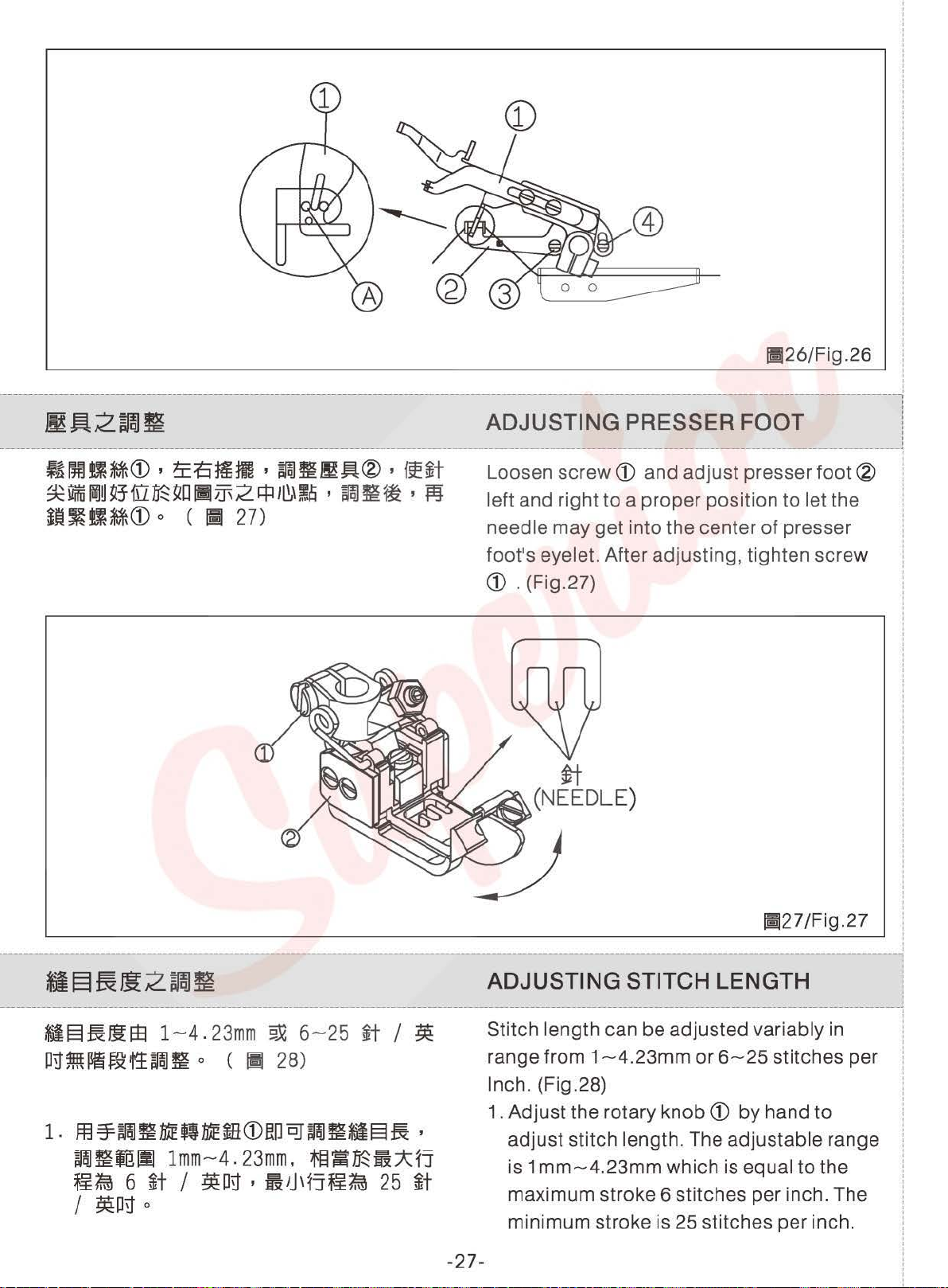
~oomaro,~£~~,~~~~®,~~
~liffil~~~J-[l~~D
;~~tiM®
llim2.~ll~H~~
o (
if~
27)
'
~~~
' fij
Loosen
screw®
and adjust presser
foot®
left and right to a proper position to let the
needle may get into the center of presser
I
'
'
I
I
I
I
i
foot's eyelet. After adjusting, tighten screw
ro
. (Fig.27)
I
I
I
!
i
!
I
I
I
I
j;j27/Fig.27 i
I
i
----
Sil§:fjt!Jt;Z
------------------------------------------------1
-§~~~ 1 ~4
P!Hftt~~f:t~~
~JU~
.
23mm
o (
9.lG
6~25
~
28) range from 1
~t 1 ~
ADJUSTING STITCH LENGTH l
Stitch length can be adjusted variably in 1
Inch. (Fig .28) !
1. Adjust the rotary
1.m~~~~q~mro~~~~m§~,
~~jglll
~t.m 6 ~t 1 ~on , filJ,~j~f.m
I
~Pn
lmm~4.
o
23mm.
ffi11t~~:i*:::f1
25
~t
adjust stitch length. The adjustable range i
is 1
mm~4.23mm
maximum stroke 6 stitches per inch. The :
minimum stroke is 25 stitches per inch.
-27-
~4.23mm
or
knob®
6~25
by hand to j
which is equal to the !
stitches pe r !
'
i
i
!
i
!
I
I
Page 33

!112
8/F
ig. 28
2.m~~~~~~m®,~n~~~•w
@~2Mfi~@~OO~~&~~
~§Wifm~~Qj~iJJ~em
o
R~M
3-•~~m~§~,~~m®~m~fiB
fCil~q
4.fim2~~-~~i1ltt~~,~fim~
~~ , ~H~~~f@~ihtt
~ihtt = ~~~~~~j~ : iW~~~~
~jl¥
1.
:;$:M2~i1Jtt~~
0
2.m~~~~q~moow~~~iW~~~
~~j~ , ~~ialll
,
&2~U'J'
o
1mm~
1:1
o
~~~
7.
6mm
1:7.6
o C
Ill
28)
3.m~~~~ft~moo,~u~~~·~
®~2m
~§JrolrS)Jro~Qj~~~j~
fi~~~oo~~&~~n~M
0
2. After manual adjusting the rotary
the moving distance
can be known
the
scale
3.
Turning
knob®
by
plate@
of
current feed teen
the indicated number on
.
clockwise can lengthen
knob®
the stitch length, turning it
counterclockwise can shorten the stitch
length.
4. The adjusted stitch length can affect the
differential ratio, so the differential ration
should be adjusted after adjusting the
stitch
~length.
ADJUSTING DIFFERENTIAL RATIO
The differential ratio = rear feed
front feed
dog
stroke
1. The differential ratio can be adjusted from
1:1
to
1 :7.6.
2.
Adjust the rotary
adjust the front feed
adjustable range is 1
knob®
dog
mm~
3. After manual adjusting the rotary
the feed
dog
stroke can be known
indicated number on the scale
dog
stroke:
by
hand
to
stroke. The
7.6mm. (Fig.28)
knob®
by
the
plate@
.
,
,
4-•~mMm~~,
[Cil1J1E~o
5-~~m~•~~,~~moo~~~fiB
f6.1111Elt
0
~~moo~m~fiB
sewing the elastic fabric .
5. Turning the
when sewing the shrink fabric.
-28-
4. Turning the
knob®
knob®
clockwise when
counterclockwise
Page 34

:
I
I
I
--------------------------------------------------~-------------------------------------l:
~a
-----
ffffi~m~m~§~~~•2•~~~~R
~
~1J~Jj!2_§m~
~
:t.Hftt~
~
~
.11:1:;
o (
PIQJ
Ill 2 9)
ADJUSTING PRESSURE
PRESSER FOOT :
------------------------1
Pressure
of
the presser
foot
OF
THE
should be as
light as possible, so that cloth can be feed
and sewed
smoothly. (Fig.29)
I
!
I
!
I
I
I
I
i
!
i
!
A
(
I~m~~~~-~~*M@~ffmm~~
•*m~•oo•~w~•tt~~~~~;•
oo•~~m~mAm•~mWW@~M~,
~•oo•~-~~g~~~~~wm~Mm
~m•~ff•oo•~~mk~•~n
~m~i\~Dm
30
PJTm
o
oSm
An industrial sewing unit or sewing system
must
lighting
the marking
a lamp shall be easily discernible while the
lamp is being installed on or near the lamp
socket as shown on Fig. 30.
!1129/Fig.29
LIGHTENING
OF
THE OPERATION -l
ENVIRONMENT j
always be unplugged from the local
of
the sewing area before relamping ,
of
maximum rated input
of
I
I
i
i
I
I
I
I
I
I
I
mAErJJ*·······
Lamp Max ..... l
-29-
1
oow
OOW
11)30/Fig.30
Page 35

I
!
I
I
~-;-
;~~
!-----------------------------------------------------------------------------
i 1.
' I
!
i
I
~
~~
-----------------------------------
~~lslt!:"sM«E.Ef.l~OO~F'-j~
o 1.Read and understand well the content of
---
~-~~~
this instruction book.
2.Know the functions of major parts and
understand the notices.
3.Truly realize the meanings of all warning
tags.
~~~~
N-~-~-~-~-L~-~~ ~-
~~
~~~~
---
------
4.Realize and be familiar with how
operate this machine.
5.
~f'l=~~~~i*m=~ff,fJI}!Atwm~~
6.
~~~~-~a~~~2.I~~o
·
tJl~~tg:Ji~fi=~«E.Ef.l~H2.~~~
7
~-----------------------------------------
1
1~-
~----------
:
!
I
I
I
I
A
I
I
~Turn
i
!
:
'
'
I
'
"'
i
!
\J/1:'
-
-----------------------------------------------------------
~~f'I=~M , ~~w.Jiif~)J9-
off the power switch before carrying out cleaning. The machine may operate if
the treadle is pressed incautiously, which could result
7JD
~
m
~IE
~D
lii
~IE
B~ ' ~
~51~~~
Be
sure to wear protective goggles and gloves when handling the lubricating oil and
grease so that they do not get into your eyes or onto your skin, otherwise
inflammation can be resulted.
0
o
0
A
o
=~~~iJ.JmJ
~~
~
~~
)!~CAUTION
1*
~
P~
5.0perators have to keep well mental status.
6.0perators shall wear appropriate and
proper working suits.
?.Develop the familiarity of how to operate
MAINTENANCE
!Ul~ , m*'l~111f'I=~?!J~A~~1a
m
~D
3=
the machine if needed.
~
-
---------------------------
in
injury.
'
JiJ.
WJ
~
m
~IE
it
A
P~
t:P
9JG
to
o
)~
?±
&:
-
•
"')M)~51E9JG~51E1'~fR.Ef.l
\JI
~U
-~~MM*'l~~~~,g~m~~«em,
••amli..Z~-o~~,m~~w•s~~
*«Em ,
~j~jf~fll«E.Ef.l
Furthermore,
and diarrhea. Keep the oil away of the reach of children.
A
*l*'l~:aw1¥1Jl'9JG~~~
se
both hands to hold the machine head when tilting or returning it to its original
position
~3=~~~,~-*'1~~~-~~~M-Mm~~~~~o
If only using one hand to move the machine, the weight of the machine head may
cause slipping and you may get hurt.
~~ff<AEJtEJ~fi~
..
do
not drink or eat the oil nor the grease for they can cause vomiting
§
0
'
~~U~ff51~1GiO±~Dili~
,
~~li..Z!!¥3=itfj~f'l=
(~4)
11-j~~it
o
For keeping the machine quality and
lengthening the usage term of this sewing
machine, please maintain it everyday.
addition, before first use after a long idl ing
time, please
periodical maintenance items (Table
maintain.
-30-
,
~~~IEl&?'ftj\~~1'~U~ttBJ5
follow the following the
4)
o
In
to
Page 36

(()i~~~~i*lt:Bit»
1.m.re~~
2
.~~filti~<Dml'
,
~~ml'it~®
(Maintain the feed
1.Raise the presser foot.
o
2.Remove two
dog)
screws®, and then remove
the needle
3
.~t\!=EfrtiU~~~ffi~@..t~ffi~
4.~~~~£1-t&®~..t
0
o
CIII3D
3.Use a soft brush
the feed dog teeth@. (Fig.31)
4.lnstall the needle
above cleaning.
plate®
.
11131
IF
to
clean dust and lints
plate®
after doing the
i g .
31
on
<
hD)ElHL~1ttB9~tt
l.~?f.iwt~15J(f!I~N3~~
2
A~H~
1M
1JD
5!
~
WH'f
JU
~
110
)EIHl'iJ
>
5HHL
®
ill
fl
~
Ul
l'
:
iii
Iii
110
tt
:
l!l m
5fB
,
in
«Maintenance of lubrication
holes»
1.
Cleanse the fiber and dirt.
2.
Weekly add the lubrication in the
fueling holes.
The positions needed to be added
lubrication as
below:
the fueling
-31-
Page 37

f*itiHi
f*Itr~§
Maintenance Cycle Maintenance Items
l.$~~~~l:Zflfi~
1.
2
~~
Daily
.t~F~;aum~a~~~z;&~;m
2.
3 .f* ~
3.
l.f*~~)JJR9i-ll~~
1. Keep the power
~~
Weekly
2
2.
3
3.
~=@~
Quarter!~
~~
Annually
I.~~;m~P3z;~~5m
1.
l.ru~1til.J&:~~a~29X~m
1. Check the transmission belt to see
o
Clean the lint on the feed dog.
o
om;a;mmz_t,
l'~rHIT5l~a5JJHMD
Check if there has enough liquid oil inside the oil pan. (The amount
should be between the red up and down paint mark of the oil level
gauge.)
~
H
:&
tl
1'F
~
)~~
KeeQ
the machine and the OQeration table clean.
cords
.f*~tli'FOOH.&~~
o
0
looking clean and neat.
o
Keep the operational panel clean.
.tn~~)JJR~f~~a~mt9X?ilE~U1~
Check if the power parts is loosening
0
Replace the liquid oil inside the oil pan.
0
~4/Table
4
0
or
still at the right position.
- -
if
it is weariful
or
damaged.
2.ffi~~~H?i&~MB~a~~·~~
~~H?iRfflM@·~~~a·Q~B
MA~a~~~H$·ma~~~a~
t~
m _t
1'
~ 2 r~
~o
OJ
o <
111
3 2 , 3
3)
1.Piease use
Equivalent pi
Mob
I.
il#1 0
or
ESS0#32
or
its
2.The lubricating oil has been drained from
the machine before delivery. Therefore,
before using the new machine, remove
screw
between the high/low indicate lines
(A)
, and fill the oil until the oil level is
of
oil
level gauge. (Fig.32,33)
-32 -
!ll32/F4
g.
32
Page 38

3.-~@~mm,w•~e~~m~•~
m2~~,@~ro~•~,=~u~~
~~'affW,M~@~~®~m*M
1~an1~~
*~•2•~u~~~*~m~~-~~m
~ , ~~H±
o
ffit
~
..t
~
mH£
no
;anrl.l
m o
3.Be sure
if
oil level is lower than line L
gauge.
*Before
machine which has
more than a
needle bar.
to
check
starting a brand new machine or a
every
couple
day
and refill the oil,
of
not
been used for
of
week, oiling
oil leve l
the
!ll33/Fig.33
LUBRICATE AND THE COOLING OF
NEEDLES
Fill reservoir
prevent the thread from breaking. (Fig.34)
AND THREADS
<D
and®
with silicon oil
to
lii34/Fig.34
CHANGE
----------
1.
~l'**
~~j~~
2.•m~~~u•®,~~oo~~m-~
~~~~-~,m~~-~~~~~-
D
~~ ' ~}ftHI2}f:BjG:i:~HiJ
o (
!lj
35)
---
---
--
-33-
----
1. Loosen screw D and fasten it after drain i
all the oil from
2. For extending the life
change oil after the first
After that, change oil every four months . !
THE
---
LUBRI~ATION
--
-~-----
the
tank. (Fig.3
of
the machine,
OIL J
--~----
5)
--
:
l
I
'
i
month
operation. :
i
i
!
'
I
Page 39

'
I
!
I
'
'
'
'
:
'
'
!
1---------------------------------------------~--------------------
t
t
1JI5S3H2!!!~
t
\-----------------------------~~--·------~~---~--------------------~-
!
¢:
..
B~8U~~j,I)S3ft
i
Hif:EOl'm5it
'
~~~~f~~WT~
'
M9~~ffl-@IF.I~
0
(
~
36) and the filter must be cleaned every month.
CHANGE THE OIL FILTER
This machine is equipped with an oil filter,
tli35/Fig.35
j Replace the filter
i
I
'
'
!
i
!
'
!
:
'
i
!
!
:
I
I
'
i
I
:
:
I
!
i
!
~--
1
~t2~~
:
'
!
1.
'
'
I
i
2.~oogaro~ml'~·~WT~~~~~
'
'
'
'
'
'
'
'
I
'
i
!
!
'
I
I
I
3.
'
'
i
'
'
'
*~-
'
I
'
'
I
'
'
' I
I
I
--
--
~m*t2JJtm~R"1"~~$
fiB~·~~~2§~~~~2o
37)
milft~~t,aro
..
~~2~~m•~•m~~o
0
~ ( ~
5)
(~
REPLACE
1.
See Table 5 for the sizes and the
specifications
2. Loosen screw
needles. Insert the new needles into the
holder holes as far as th ey can go, and let
the long groove
(Fig.37)
3.
Fasten screw ro .
*Needle
to conversion chart.
-34-
size
if
necessary. (Fig.36)
IIJ36/Fig.36
THE
NEEDLE
of
the needles.
ro
, then pull out the used
of
the needle fa ce you.
of
special model, please refer
Page 40

---
~1~5m
Needle System
ORGAN UY128GAS
ORGAN
SM1
0148
2~t
2 Needles I
~5/Table
#10
~t
3~t
5
0 X
R
"tr
Needle Size
3 Needles
lil3
7 /Fig.37
4~t
-
-
4 Needles
--
#10
:
I
i
I
i
I
I
I
----1
~~5RmM~~
---------------------------------------------------------------1
~~~*~~moo=~*~•w~~~,~
~*·~~~~m~aw®na,~~~a
~~~*~~-~~m~~m•,~~~*
~~w~,~~~~*~~~~~~,~M
~~-~~~-,H~-~®~M~,m~
~~~=~~-~~-~~,Bft~M*~
*~*~*~
0
(
Ill
38)
ADJusTING END INTENsivE
sEwiNG
The instruction of pneumatic end intensive:
End intensive sewing function- hook the end
intensive sewing driving
chain®
sewing driving
which
and stretch down the end intensive
lever m by foo t-action,
enable the end stitch more intensive
and strong. The standard equipment
lever m by the
of
end
intensive sewing is foot-action, but the
electronic motor
control box can be option
too. (Fig.38)
1
i
:
I
-35-
;!38/Fig.38
Page 41

I
:
:
'
'
----------------------------------------------------------·
l&~lm1~
[
.~----~--~~----.w----~--------------------~-~------------------
0
I A
I
&
No.
1.
2.
1:E5i~"J~~~~~~2.M
~~tii1J1'F,
~~~.A~~iS
Before processing the troubleshooting, please turn off the power switch and unplug
the electronic cord. Otherwise, if touching the start switch incautiously, the sewing
machine
will function and will probably cause injuries happened
l.Yl~
Problem
~tjj:t:~~m/m~
Needle thread too
~t~~i1~~~~
The skipping stitch
tight/
of
needle thread
loose
,
~~5t;fUlr-f.l~)~sltz~t±:l~)~
o
TROUBLESHOOTING
...
--~---
..
~----~-----
5!~CAUTION
,
eHW~D~~g~itJrmrsJJ
on
operators.
~~&~~
I
~
-~
t~~:t.J~t§~:j:;:§JG~/j\?
The tension
too tight?
©~~~t~5N:t.J
Adjust the needle thread tension.
1.M~tffil31Hl1'~
Choose the wrong
©ilt~Hfc~~ffl~~M~tW*I~5mti~
Select the needle and thread number match the
fabrics.
2
.m~t1'~?
Bad needle?
©~WTM~t
Change a new needle.
Exam
of
o
and Adjustment
the needle thread is too loose or
o
?
needle?
o
3.giD5i\1'IEfii o
Incorrect threading.
©t!l~~~-0
Follow the threading diagram.
4.M~t~~1'IEfii
Incorrect needle installation.
©mwr~•m~
Reinstall the needle to make the long
I
needle face the operator.
5.M~t~t~lltJT9JGIUB
The needle
©~wrm~t
Change a new needle.
6.~~t~t~W~
The looper
©~ffl~E9JG~WM•e
Polish
replace
tip
o
tip
by
the oilstone or fine emerypaper. Or
with new looper.
o
,~m~m~~~~~•
o
is broken
o
is blunt.
or
bent.
,9JG~M~fi
slot
o
o
of
,
~
7.~~H~5N:t.J:t:7::9JG:t:'J'
The looper tension is too loose or too tight.
©il'i'~~-~SN:i.Jo
Adjust the thread tension properly.
-36-
o
Page 42

No.
2.
m~
Problem
£t~ftillS~~~~
The
skipping
o
stitch
of
needle
thread
I
,
8.~jt7f'~Bf±:EifHljtfi5J~~
il~~~~jt
The
looper can't hook the right needle thread loop
1 and cause the right stit
©
±:~~~jf**l!t;;t'J'
Because the needle thread loop
increase the thread take-up amount.
9.
~
jf
1'
~m~t*t
The
looper can't hook the left needle thread loop
and cause the left stitch of looper thread skipped.
©
±:~~~jt~ltt;;tl\:
Because the needle thread loop
decrease the thread take-up amount.
1 o.
~
*t~
jt~W~*t**~~~
The
looper can't hook the middle and left straight
needle thread loop whi
left stitch of looper thread skipped.
©
~~-~~~tiW~fifi5J~~g~.~~fi~~
j;;:Jj\~=
Accordi
thread connection between needle and looper and
make proper
0
fftl
B
f±
o
;n
~
0
ng
to the standard to adjust the looper
m~JSH1~~
Exam
~
tt
needle thread loop size.
iA
q:t
and Adj
~
jf
rdl
w
t
o
ustment
·
~,5X~jt~Fi5J:E
ch
of looper thread skipped.
•
iftDD~~~-
is
Fi5J
**
Ii
· ~
.5X
'
~g)-~~~
~
il
~ *t
ch
cause the middle and
-
is
~
~~t
o
too small which
~
jt
~
Fi5J
~
iA
0
too big which
. ~ *t
~
Fi5J
q:t
11.~*tmtm~ttq:trdlfi:Eil~*t~~
jt
~Hf@
:E
jt
**
~~
jt
o
The
looper can't hook the middle and right straight
needle thread loop and cause the middle and
right stitch skipped.
©
m~M~~a~~~~**H·~~~~Fi5J~~M
~ • ~rc~~~~-iifJ~~
Check
gripper
of
problem,
12.~~tW~*tlic~1'=
The
l©m~~t~~M . m*t~~~t2fMlfi5J~~
Check
synchronization
13.!fijtW~jt
The
cooperate
if
and the
thread
looper
the
needle
the
thread
synchronization
controlling
adjust
needle
well.
it
and
needle
between
J=lftC.
~1'=
and
the
pass
according
o
lever
needle
cam
didn
height
o
o
through
. If
't
needle
guard
•
~*t~fi5Jq:t
the
relationship
there
is
to
the
standard.
cooperate
and
the
and
plate
thread
any
well.
o
looper.
didn't
-37-
Page 43

No.
m~
Problem
I
m~&~~
Exam
and
Adjustment
~~~m~~~o
2.
The
skipping
m~~~~tfJmm~§.X~~ ~~fi~mo
3.
Skipped
at
sewing
4.
Ill~
Thread
broken
stitch
stitches
start
-
of
needle
or
unraveled
-------
thread
thread
l©~!~~n~~~mm·~fi~~.m~•
mrJ~~
Check
plate. If
according
14.ijl~tRJ:~~tft2'81'~
'
i§~J:~~t~~~t
The
needle
well or
the
up
© m
~
*
·
~Dfirc~M
Check
thread
any
problem,
I
standard
The
needle is too thick.
©tiEffltt~~~~tJj\-5!12e'SJ•~t
Try
using a needle with a count that is one lower
than the current needle.
2
.u~~m~~ . s~~l!f~'~
The
sewing speed is too fast at the sewing start.
©tiEfflti~~-
Use
the slow start feature.
1-.
g
=--=--
~
=--lJ-:-),..-:-
Incorrect threading.
©nl:~~~~~m~g~o
According to the threading diagram to
2.
m~t~~:::f'IEiil
Incorrect needle installation.
©m~~~mfi
Reinstall the needle to make the need
the operator.
3.
fJ
~
5ltt.H~
The thread tension is too strong.
©i~Hit~~u~~:t.J
Adjust the thread tension properly.
o
the
position
there
to
and
the
incorrect
looper
~t
n J:
the
size
output
.
~1'
IE
::*:
of
needle
is
any
problem,
the
standard
0
up
looper
up
looper
skipped.
~
~t ~ftC
.
t3l:~•m~j~~
of
needle
amount
adjust
0
iii
o
o
·tiEmfi~~~~~•o
o
o
-g-
of
it
according
and
needle
adjust
.
•
9.XJ:~~tlli~1'!~
didn't
position
R
-rr
& J:
and
up
up
looper. If there is
o
o
it
cooperate
~
o
loope
to
the
re-threadin~
le
slot face
guard
cause
~
tfJ
r and
**
•
the
4.U~m•~~
Bad thread quality.
©~,EF.HI'M
Change to use the proper thread.
s.smtt~t~m
The
thread is wider than the needle hole.
©
~
~ii~:P
Change to use the proper thread or needle.
-38-
~~
rr~HiUi
o
0
o
~
~t
o
Page 44

No.
m~
Problem
m~EHJ~~
Exam
and
Adjustment
4.
liT~
Thread
IIJT~t
5.
Needle
broken
broken
6.~~t
©
?.*it~~m~ffi~~~m~~~
©
1.
Choose the wrong needle.
©affi~::f~~ftJLErSJm~~·~fflm-~ErSJ~fto
2
.~~~~1'~
©~R~@E~ffl~ft~~~~~mft~~~o
to the central point
3.~~~-f§]g[I&::f!~
The assembling height
©~~~~frSlf§J~
the appropriate presser foot pressure.
4.fi~1'~
©~~~S~~~~m~~~-
5.
©~-~~IE~~-~~
6.
©~~-~t
'~jt
=E~9.X~~U1J!!Ji~
The needle, looper, needle plate, presser foot
tongue and thread crossing hole is blunt
scratching.
~~E9.X~WM~M&E·9.X~~-~~o
Use oilstone or fine emerypaper to polish or
replace the parts .
'jt~
'!t~~
0
'~~JL~~~~~
or
o
Sewing the heavy material cause the thread
winding.
~g•s~•·•m~~~gft&~-~~-
Decelerate the sewing rotational speed and
applying silicon
between needle and thread .
mjtt:rsJmt~1'~
Use
thick
needle within the range that there will be
no pinhole occurred on the fabric.
Improper assembling
During assembly, make sure the needle can insert
f~H~@=~~~1J
Adjust the feed dog height to make the feed teeth
in
0.
8-1
mm higher that the needle plate and keep
Bad threading o
If there is any connecting part
needs to be dealt first. Then, threading.
~~t~•::f'IE~
Improper needle installing.
Install the needle correctly
instruction book.
m
~t
!taB
9.X
The needle is bent, the needle
needle hole is blocked.
Replace the needle.
oil to lower the friction temperature
o
0
of
the presser foot.
of
the presser foot.
0
of
feed dog is wrong.
•
~~~~~t~o.a-1
o
0
·~MW~
of
the thread,
o
~t
0
~
ltfi
R
·~B~R
~
=E
9.X
by
following the
jt
JL
o
fRl
ti
a:
tip
broken, or the
mm,
o
0
!&]~
o
it
-39-
Page 45

No.
5.
IT£t
Needle
Problem
broken
~~
m~&~~
Exam
7.
~?J:!t:JJ~Ij\
The presser foot pressure
and
Adjustment
'~ffi:ff.&
o
is
small or the fabric
feeding is improper.
© tt
no~
!il II! n .
fiE~
ffi
IE
m o
Increase the presser foot pressure to adjust the
fabric feeding
a.
~~t~mjtffi~
properly.
o
The looper contact the needle.
©
~~~Wr!J~~~twm~
taz~
o
Adjust the position of needle and loope r according
to the standard.
9.
_r~jtWmjtffi~jM
o
The up looper contact the needle.
©~~~Wr!J~k~j
twm~taz~r
o
Adjust the position of the upper looper and needle
according to the standard.
1o.m~tw~~th"lc~1'
..
o
The needle and needle guard plate didn't
cooperate
©~~~~~mj
well.
t!fiHI~t
h"llilf o
Adjust the position of the needle and needle guard
plate according to the standard.
11.~~t~ftH
The looper
©~~~~t
0
tip
0
is blunt.
Replace the looper.
12.jt~W~t~E~I!t~~7\:
~j}Jo
The needle lever and needle lever sleeve
out so the
©~~~H~9JG~t~E
needle and needle sleeve become loose .
fql
'fiEm~tWjtf~EIC~
is
worn
o
Replace the needle rod or needle rod sleeve.
13.~t~L~~t~:;t:Jj\
o
The needle hole on the needle plate is too small.
©~~'J\5ift
Replace the smaller needle
bigger
14J!f!1=~111~7\:
m~t9JG~~~~t~~7\:~t~
or
the needle plate with
o
needle hole.
0
The parts is over-loosing.
©~•s
aRn·~~-~~mM~~B~~o
~m2~~aw•~~~·~~~~~~e
Check cooperation and wear condition among the
mechanism and adjust the size according
standard.
Replace the part which is worn out
to
seriously.
the
-40-
Page 46

No.
5.
IIT~t
Needle
broken
!Jt~
Problem
m11It&~~
Exam
A
and
Adjustment
~.!~CAUTION
~~~~~~~-~~fi·~~~ti-~-~-~
IJX~U
fi.A~fBI!!
In
order to prevent the broken needle sticking in the
material and stab people so please search for broken
needle until the whole of the needle is found.
o
6.
**
liWi
1'
~~
~u
Uneven
*1~/f'SiZ!'i
7.
Uneven
*lffi~~Jte
8.
The
stitch
Seam
fabric
is
puckering
1.m~t:t:it.t~m~t~llff~~JX:t::;;t;::
~IH±-~
The lower needle cause the big thread loop and
make the thread
©~~~mWf:@rum~tr.lijM
Reset the needle height by following the standard.
2.~t~~fi~OO:t:~
~~::f~J!~U
The needle plate tongue is too narrow which make
needle come close easily and have uneven
the
stitch.
©J@~Wf~tt&
Replace with the new needle plate.
3.m~t~~~t~e~1'~
The needle and looper didn't cooperate well.
©~~~~~m~t~~~t~c~ruiiii
Adjust the needle and looper position by following
the standard.
l.JI!~/!!JJ~Ij\
The presser foot pressure is too weak?
©~~l!Hll!!t.J
Adjust the presser foot pressure.
2
.~~~ii~it.t
The feed dog teeth
©~~~~~
Adjust the feed dog teeth height.
l
l.~iJJ~ffitt$1'~
The improper differential fabric feeding ratio.
©iltii'~~
Adjust the differential fabric feeding ratio properly.
2
.~~~Qir.lij@;ijij~[l~1'~
The improper position
©~~
I
3.M~~t.J~:;;t;::
©il~~
~maJ~~~~~r.lijft_t
According to the standard to adjust the feed
teeth height.
The stitch tension is too strong.
Adjust the stitch tension properly.
o
loop intertwist together.
•
~m~tlli~~~~itHirrn~Wli
0
0
o
?
o
0
is
too low.
~~Mo
0
~iJJ~ffif:t$o
of
o
~fi*iSNJJo
o
feed
0
.
~~11!2mJffig
o
0
dog
teeth.
dog
-41-
Page 47

No.
8.
*~
m
~u~~~
The
fabric
l~~
Problem
;re
is puckering
tn~&~~
Exam and Adjustment
4
.J.It~JB1J:;t:;*;::~:;t/j\
The presser foot pressure is too strong
©
ii~HJa.J
g
It~
IUJ
0
or
o
Adjust the presser foot pressure properly.
5.
~*'1~jJ{~~
0
The sewing speed is too fast.
©~f~guJ~jJ{
o
Decelerate the sewing speed.
too weak
9.
~fm1'~
Improper
10.
*iffi~t±H~~t3L
stitch
There is needle hole on
the
fabric
l.JR~*H*IB1'-~
0
The thread thickness is different.
©B(Ff.U~~~~~~
0
Change to use the better thread.
2.
~JRHif'F1'.IEm"
The thread gripper
©~ll*~~Hw~m I ff~~~~~~~
o
is
abnormal.
o
Clean the thread waste on the thread gripper
make the thread crossing smoothly.
3.j§~H~[l1'.IElii
I
J
~he
locating of thread crossing is incorrect.
©~~fi~'~fi~&k~fi~~~1Jo
o
Adjust the tension of needle thread, looper thread
and up
4.j§~~1'J~Gm
The thread crossing hole
©fflfi'J>it~~7JI~WJJI6j§~~
looper thread.
o
is
not smooth.
o
Use emerypaper or file to polish the thread crossing
~ h_
ol
~e~·~~~~~----------
1.m~t~t~w~~ie=E
o
----------~
The needle tip is blunt.
©~t~Ul!~t
o
Replace the needle.
l
2.
~-m~tt~
I
m~t:;tm
o
The needle which compares with fabric is too thick.
©~m
~*lllm~t
o
Replace with the fine needle.
to
3.~t~k~~t;R.:;t'J'~em
1
The needle hole on the needle plate is
worn out.
©~~tt-&~f~lllm
Rounding and smooth the needle plate hole.
-42-
o
too
small
o
or
Page 48

加裝CL如 遇抬壓 腳 力道 不 足時 。
15.
If the strength or the presser foot
lifter is insufficient with being
equipped with CL.
請依 下 列實 施 :
A.參數64項 ,出廠 值 :40 改 為100
B.參數65項 ,出廠 值 :10 改 為28
P lease implement the procedure as below:
.Parameter No.64,default: 40 change to 100.
A
Parameter No.65,default: 10 change to 28.
B.
Page 49

:
'
:
~------
'
:
:
'
'
'
'
'
'
'
'
!
'
'
'
!
'
'
'
I
:
!
:
'
'
'
'
'
'
'
'
!
i
I
!
'
'
I
i
!
:
'
'
'
'
!
i
i
I
'
'
'
'
!
i
!
!
!
_____ ---
i
'
!
!
i
I
:
!
:
I
I
'
i
I
:
:
:
!
i
!
:
'
'
i
I
'
i
'
'
'
'
'
'
'
'
:
'
i
!
:
'
'
i
I
'
i
'
'
'
'
'
'
'
L---
'
'
'
'
:
!
'
I
I
I
- ---
------------------
-----------------------------------,-------
I
I
I
I
I
C\1
--~
~
~'-
~
~
~
ct
CJ
<(
-
Cl
CJ
z
Cl
<(
w
ct
I
I
--------
--
~
--
I-
T"'""
~
1'-
I
0
0
()
ct
0
LL.
~
<(
a:
CJ
<(
-
0
CJ
z
-
0
<(
w
-----------------
i
I I
'
_l
_
---~-~------·
a:
1-
Page 50

---~-~-----------
C\1
1--
1
1'-
0
0
(.)
....
-------------------------------------------------------------------------------------------------------------------------1
' '
' '
I '
I =ttJI•.l:NMI !
i C007J/C007JD/C007K/C007KD/C858K/C858KD/S007K/S007KD SERIES
I
•«z:/UNIT:nm
i
FOR
I
I C007K-T2-1070
I
'
i £
l
CRL.CRL/UT
.IJTWR"ti..~/DIFFERENCE:±2
C007~~1200~:12.3kg±5"
~
U(L):1070~:11.3<g±5"
&•
EP~
~
C1>
'&
~
.-1
I@
~
~
III
TABLE
~ ~
C\1
CUT-QUT
~
SEMI-SUBMERGED
<1-t-
01
\!l«l
_...,
l I I I I , !
'
'
' I
I
I
'
'
i
I
1
I
j
I
!
!
:
I
I
LL
0
!
1
l
~
.-1
~
I
ll
:&[
--;~*
'"
1--
::::>
0
._!.
l
11:
j J
~~
~J
,-K
~(
~
::::>
(.)
I
~ ~
w
....J
m
~
,....
1--
1
1'-
0
0
(.)
LL
0
1--
::::>
0
t-!-
::::>
(.)
w
....J
m
~
________
I I T
' I
J
'
I
I
I Cl() "
I
o I
I '
·-
·---+
---··-·---·---·-··---·-------·--·-·---·-·---------------
j
1
C007J/C007JD/C007K/C007KD/C858K/C858KD/S007K/S007KD SERIES
'
~-~
1
•«z:/UNIT:mn
I
FoR-~t•Re.-
I
JSJf:tiR"ti..'i!/DIFFERENCE:±2
l C007K-
l C007K-T1
~
~~-&-
...J
Tl-1070
U(L):1070~:11.5kg±5"
B(L):1200/U:12.5kg±5"
~
~
OC\1
NO»
...,
"""
tfT
gzz-
- - - - - - - ----
!cb
l I I I l i
I
l
l
j
l
l
I
I
jl
1
I
: %
I I
l
_______l
g~~
;=
l~·
,
I
!
I
og
i-
1
I ;
'
0-'--
i ~
I I
_______________________________________________________________________________________________________________________________
...J
' I
...!.
~-
~
U>
~~SST
(')
~
~~~
$
:::
/"'
~
J'
~\
~
It)
C1>
~
~
"
N~
/f---1
../
!+-----'---<~--
f6
It)
9t
gzz
~~ i~
~
....
~c ~
...,.
J
0 " 0
...,.
M N
~~
og
/
[
~
'&
\.\~
;:!:
C\1
ir~l
oe
II
._...
TABLE
ml-t-1
~-
S?
~
~1-t-
~~
C\1(\1
I
111-:::
•A
en
~
.-1 .-1
CUT-QUT
J;
U>
(')
~
f
0)
~
~ ~
-----
~
...
- i
===
-==
~
ni
i i
~~;
·~
ote
1
IJ
-
ose
<IP'
"0
co-.
0
-----
<1-t-
:8-fl l i
~
f-
~
~I
ct
<too-
~~
-----------
SEMI-SUBMERGED
0
,-Q?S
-=1==
-1-ZS£
Ill:
I-::
~lj
'1\r\
...,
~
'&
--t-
a~t
1-
£t£
0 i
~
I -
OOZ
SH
1-
T9
:-
gz
0 i
1\!
l :
_____________
o '
i
!
:
,
:
I
!
!
I
I
I
]
!
~
'
'
~~
!I
1
~
!
!
i
i
'
:
I
•
i
!I
:
I
!
i
:
J
I
'
'
'
'
I
'
'
I
'
'
' I
Page 51

1.8~H~~--~-*~~
~m~u~~~~~ , ilg~f*m~m&~
,
fi-~~
fff<ftmlo
2.Mfi~~H~~@~~M~~ft~*~
ftOO
3.~ttEffi,Mfi~~OJ~~~~-~,
@~~~m~•~~OJ~~m~~~w
iffl1'~~!B~~i~
=
(1)
PfffimE,
~~~~~itt
(2)
~H~1tt
C3)
~*i~~~ : E~ , ~'11 I OJilf!*i~
~J=io
C4)
~-= ~-~• , ~ , ~mw~~
,
~iinafl~•
OJi~lUi~i§i&~~~~l=
0
:
OOruJ
,
~~fV3H~~
o
0
o
1.
When the machine needs to be eliminated
and demolished, certain basic rules must
be observed to protect the environment
and public health.
2.
ALL machine components must be
divided according to categories as the
followings:
(1)
All sheathes, flexible hosing and
plastic or non-metal components.
(2)
Electricity components: switches, or
lighting components.
(3)
Insulation materials: rock wool, and
Flexible rubber strips.
(4)
Metals: ferrous metals, copper, bronze
and brass, various.
3.
In
this way, all materials can be
eliminated correctly, recycled, or melted
down for reuse or disposed of so that
they
do
not
harm the environment.
-46-
Page 52

MY127K.DEC.2013
 Loading...