

Page 1
BH780
1~FF.J
~
SJ3
-~~1~
(;)
INSTRUCTION AND PARTS LIST
[/411®
C€
~
~~JK119~Jl~f]a]
KAULIN
MFG.CO
.•
LTD.
Page 2
TO ENSURE SAFE USE
For the sewing machine, automatic machine and ancillary devices (hereinafter collective ly referred
"machine"), it is inevitable to conduct sewing work near moving parts of the machine. This means that there
of
is always a possibility
operate the machine and maintenance personn
machine are strongly recommended
before using/maintaining the machine. The content
contained in the specifications of your product.
sk
The ri
of
indications are classified into the following three different categori
the labels. Be sure to fully understand the following description and strictly observe the instructions.
unintentionally coming in contact with the moving parts. Operators who actually
to
carefully read
OF
YOUR SEWING MACHINE
el
who are involved in maintenance and re air of the
to full
y understand the following Sa
of
the I
Safet
y precaut
io
ns I includes items which are not
es
to help understand the meaning
fety prec
to
auti
as
ons
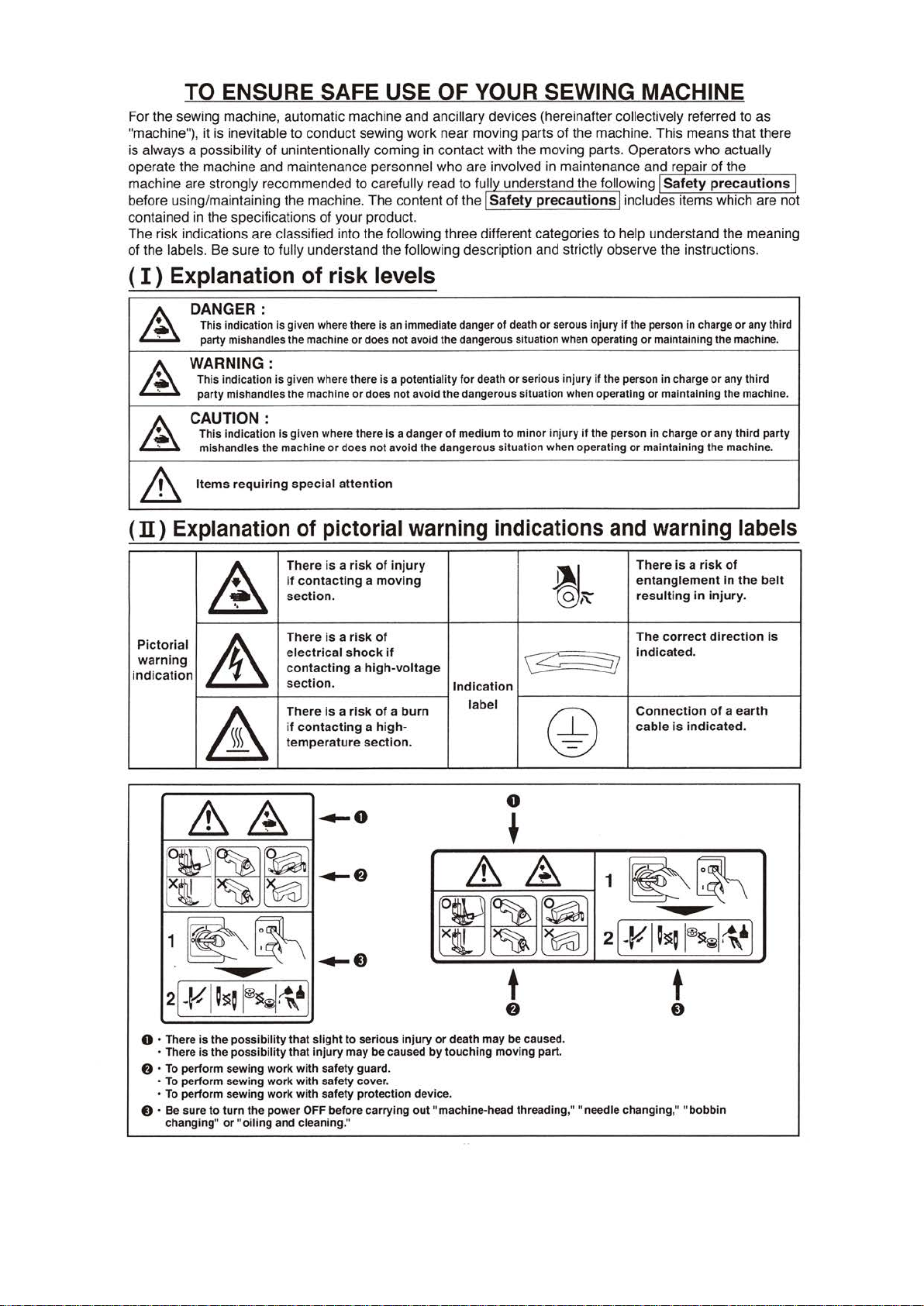
( I ) Explanati
DANGER:
~
~
~
This indication is given where there is
party mishandles the machi
WARNING:
Th
is indication is given where there is a potentiality for death
party mishandles the machine
CAUTION:
This indication Is given where there Is a danger
mishandles the machine
Items
requ
&
(II)
Expl
anation
~
Pictoria
indication
warni
l
ng
it
&
on
of risk levels
ne
or
does not avoid the dangerous situation when operating
iri
ng
speci
al
att
of pictorial
There is a
if
contacting a mov
section
.
There
is a risk
elect
rical shock
contacti
secti
There
if
tempera
ng a high-voltage
on.
is
a ri
contacting a high-
ture sectio
an
or
or
ention
immediate danger of death
does not avoid the dangerous situation when operating
does not avoid the dangerous situati
of
medium to minor injury
warning
risk
of
injury
ing
of
if
or
serous injury
or
serious injury
if
on
when operating
if
the person in charge
indications
~
~
~
In
di
cat
ion
sk
of a burn
n.
label
@
if
the person
the person in charge
or
and
T
e
r
The corr
ind
Connecti
cable
in
or
maintaining the machine.
or maintaining the machine.
maintaining the machine.
warning
here
is a r
ntanglement
esultin
g in
ect directi
icated.
on
is indica
charge
or
any third
or
any third
or
any third party
labels
isk
of
in
the
injur
y.
on
of a eart
ted.
belt
is
h
0
&
~
~·
*
~f)
~~~
LL~~
1
~~
....
2
[·¥1~~
0 · There is the
• There is
f)
·
To
perform sewing work with safety guard.
To
perform sewing work with safety cover.
•
• To perform sewing work with safety protection device.
0 · Be
sure
changing"
~N~~
possibility
the
possibility
to
turn
the
power OFF before carrying
or "oiling
~o
I
that
slight
that
injury
and cleaning."
to
serious
may be caused
injury
out
&
~
1
~~
2
[
·¥
~
~~
t
f)
or death may be caused.
by
touching
"machine-head threading," "needle changing," "
movi
ng part.
I~~
-
~
I@~~~~
t
0
bobbin
~
J
Page 3
SAFETY PRECAUTIONS
A DANGER
1. When
wait
for
shock.
it
is necessary
five minutes
to
open
the
or
more before opening
control box containing electrical parts, be sure
the
A
Basic
precaution
1. Be sure
the machine before using the machine. Carefully keep
ments at
2.
The content
3.
Be
4.
Those
Safety
1. Be sure
works
2.
If any
prevent accident
3. Be sure
that can result in personal injury
change
Application
1. Never use the machine for any application other than
prescribed in the instruction manual in order
machine
2.
Never modify and alter
which
Education
1. In
only
tion and
ensure
cate/train them beforehand.
Items
~
Turnin
L
----
1. Be
failure in
2.
To protect against
ing operations after
be
stops
3. Be sure
vent
4. Be sure
5.
Be sure
age
to
read the instruction manual and
hand
for
quick
of
this
sure
to
wear safety goggles
who
use a
devices
assumes
assumes
order
by
for
-
g
the
------
sure
sure
2-1. For example, threading
threaded,
2-2. For example, changing
2-3. For example, when inspecting, repairing
electrical-shock, earth-leakage
of
and
to
operate
normally in
of
the safety
to
keep the warning labels adhered on
it
with
a new one.
and
modification
no
for
any application other than the intended one.
has been modified
completely.
electrical components.
no
and
training
to
prevent accident resulting
the
operator who has been trained/educated
how
to
the
which
-po..;er off:
to
operate the machine with safety
above,
the
-------
to
immediately turn the power
order
to
carry
out
or
to
remove
to
turn
the
to
turn
the
reference.
section
heart
warning
the
order
devices
that
includes items
pacer have
machine after verifying
can result in personal
to
labels
to
prevent accident caused
is removed, be
or
I
responsibility
the
responsibility
for
machine in order
for
or
altered.
I
the
employer has
power
to
the
machine
-
T~rning
applies
protect
accident
clhanging the
the
power
power
the
po~er-sw~c
to
the
------------
against accident that can result In personal
resulting
turning
the
the
power plug
power off. For
following
the
bobbin
or
adjusting
off
whenever the machine is left unattended between works.
off
in
the
protect against accident caused
to
following.
operations after
parts
by
case
other
which
use
the
I
sure
injury
death.
If
any
damages
damages
to
or
to
to
from
unfamiliarity with
establish an education/training plan
has
-h
-
off
if
any abnormality
from
abrupt
such as the needle,
.
all
holding
fire accident.
of
power failure
machine after consultation with a medical specialist.
or
or
off,then
component
the
~
cover
in order
Accident
1 personal
1 damage
~--------
to
prevent accident leading to electrical
to
means
to
turn
injury
or
property."
------
the
power
;to
CAUTION-------------,
explanatory documents supplied with accessories
the
instruction
are
not
contained in
that
safety device(s)
by
lack
to
replace
or
the
machine clearly
of
the labels
prevent accident that can result in personal injury
personal
prevent accident that can result in personal injury
personal
to
acquire adequate knowledge and operation skill.
to
be
-----
start
the
machine incorporating a
turning
or
cleaning
plug section instead
of
it
and verify that
death.
has
its
intended one and in any manner other than that
injury
injury
by
the
the
employer with respect
turned
~emo,;in
------------------------~
or
of
the machine,
the
power
looper
parts
the
in
order
manual and the explanatory
the
specifications
by
needle breakage.
is
correctly installed
the
device(s).
vis
stained
or
death resulting
or
death resulting
machine,
off
I
g
-the-po~er
failure
, spreader
of
the
machine
to
it
works
ible in order
or
come unstuck,
the
machine
for
the operators and edu-
plug
from
is
found
injury
be
off
machine.
of
prevent accident resulting
or
or
death.
sure
to
clutch
and verifying that
etc. which
or
leaving
the
cord
of
your
in
place and
normally in
to
prevent accident
be
from
the
use
from
the
machine
has
to
in
carry
motor
the
section in
to
the
machine opera-
the
outlet-This
the
case
out
the
, in particular,
the
have
to
machine.
order
of
cause-
death
or
off
and
of
docu-
product.
order
sure
to
or
death.
of
the
or
death.
be used
To
- - ,
power
follow
-
machine
be
to
pre-
of
break-
- ,
--~
to
I
PRECAUTIONS
Transportation
1. Be sure
to
the
text
to
lift
of
I
and
the
TO
move
the
instruction
BE
TAKEN
machine in a safe manner taking
manual
for
the
IN
mass
of
VARIOUS
the
machine.
OPERATION
the
machine weight in consideration. Refer
STAGES
I
Page 4
2.
Be
sure
to
take
suff
icient safety measures
machine in
3. Once
breaka~e
order
to
the
machine has been unpacked, never re-pack
resulting
protect
from
Unpackin_ I
1. Be
sure
to
unpack
the
personal
The
2.
Be
careful!
nails
sure
injury
have
to
check
in
order
or
to
death.
be
removed.
the
machine
to
prevent
machine in
Installation
( I ) Table and table stand
1.
Be
sure
to
use
sonal
injury
select
operation.
2. If casters are fitted
them
accident that can result in personal
(
n)
Cable and
1. Be
sure
electrical-shock, earth-leakage
section
and
the
2. Be
sure
3. Be sure
cident.
(
m)
Grounding
1.
Be
sure
caused
plug
Be
sure
2.
or
the
table and table stand
to
secure
wiring
to
prevent an extra
such
cable.
to
avoid
to
securely connect
In
addition
to
have
by
earth-leakage
to
the
grounded
to
ground
genuine
death. If
to
the
the
machine
as
the
V·belt,
star
burst
, be
sure
an
electrical expert install an appropriate
outlet
the
earth cable in
(IV) Motor
to
prevent falling
against
unexpected
In
the
it
is
inevitable
table stand,
force
be
connection
to
or
dielectric strength voltage fault. In addition , be
without
accident
accident
the
case
the
for
the
accident
table and table stand
which
during
the
injury
from
or
fire
sure
to
the
connectors
remove
exceptions.
order
that
or
prescribed
machine
position
that
to
be
accident
provide a space
the
of
can
result
use
a table and table stand which are
are able
operation, maintenance,
being applied
in
to
sure
to
or
death.
. In addition,
order
to
in
order
connector while
to
prevent accident caused
genuine
can
dropping
order
Is
crated,
Its
center
in
in
support
use
prevent electrical-shock, earth-leakage
to
or
dropping
result
in
it
order
the casters
to
of
personal
for
transportation
.
In
order
to
In
particular,
of
gravity
personal
the
prevent electrical-
product)
injury
to
prevent accident
the
machine weight and reaction
with a locking
inspection
cable
if it
Is
30
mm
or
holding
power
plug in
in
before
injury
or
to
protect
prevent accident
be
sure
and take
during
necessary
more
Its
connector
order
It
or
death.
that
not
mechanism and
and repair
the
use in
to
cable
between
shock
order
to
sure
by
earth leakage.
to
prevent accident caused
lifting
or
moving
death.
the
machine against
that
can
to
carefully
out
from
can result
order
the
, earth-leakage
section.
prevent accident
to
connect
result
check
the
package
genuine
force
In
order
to
prevent
near
the
or
fire
the
operating
operating section
the
In
nails.
in
perones
during
lock
to
prevent
accident.
or
fire
power
,
ac-
by
1. Be
sure
to
make
sure
that
the
fore
turning
2.
Never
put
in
personal I
In addition, check
If
the
3.
table stand
ad usters,
the
your
njury
if
connectors
power on
hand Into
or
to
with
rovided,
in
order
the
moving
death.
be sure that the direction of rotation
casters
In
order
is
to
used,
protect
and cables are free
to
prevent accident resulting
sections
of
the
machine in
be
sure
to
against accident caused
of
secure
from
damage,
in
personal
order
the pulley agrees with the arrow shown on pulley.
the
table stand
by
dropout
Injury
to
prevent accident that can result
by
locking
abrupt
start
of
Durin o eration
1.
Be
sure
not
to
put
your
hand pulley and
to
prevent accident caused
sure
not
to
2. Be
cover
when
can result
3. The machine
spreader, needle bar,
against Injury.
ly
stops
4. Be careful
and table when removing
can result
5. Be sure
ing the belt cover and V-belt in order to prevent accident caused by abrupt start of the machine
6. If a servomotor
Be sure
7. Never
use
accident
place
turning
In
personal
runs
In
before changing
not
to
In
personal
to
turn the power
Is
not
to
forget
the
machine with
by
overheat.
fingers,
motor
or
your
the
power on
Injury
at a
high
hook
addition, be
allow
your
Injury
used with
to
turn
hair
or
or
while
death.
cloth
trimming
to
turn
or
death.
to
machine,
off
cooling
clothing
the
surround
the
bring
the
any
other
from
be
sure that the machine and motor completely stop before remov-
the
in
opening
place something near
by
entanglement
fingers near
or
speed. Never
and
sure
the
thread.
fingers
the
machine
or
off
and check
the
the power
the
close
those
that
can
area
mach
ine is In operation
your
hands near
knife
during
power
off
parts
or
replacing
motor
does not
order
to
prevent accident caused by abrupt start of
of
the
to
the
moving
sections
result
of
motor
while
In personal I
of
the
needle
the
operation in
and
check
to
your
body
it
on
the
table
produce noise while
power box shielded in
sections
the
moving
be
to
such
machine Is
njury
or
death.
or
inside
in
order
be
in
the
order
to
prevent accident that
sections
to
protect
sure
that
the
caught between the machine
order
to
the
and looseness be-
or
death.
the
casters
or
with
the
machine.
as
the
handwheel,
In
operation in
thread take-up lever
such as
machine complete-
prevent
machine Is at rest.
order
looper
your
hands
accident
or
motor.
to
prevent
the
motor.
order
,
that
fire
Page 5
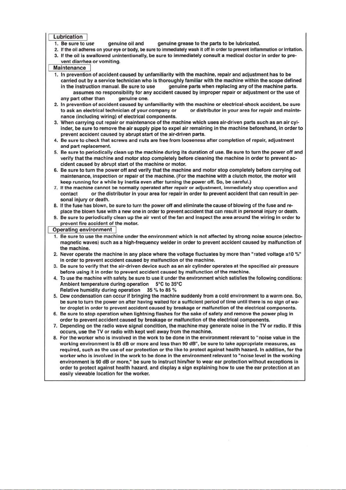
Lubrication
1. Be
sure
to
2.
If the oil adheres
3.
If
the
oil
vent diarrhea
use
is
swallowed unintentionally,
on
or
vomiting
genuine
your
eye
or
.
Maintenance I
1. In
prevention
carried
in
the
Instruction
assumes
any
part
2.
In
prevention
to
ask
nance (including
3. When
4. Be
5.
6. Be
7.
8.
9.
carrying
inder, be
prevent accident caused
sure
and
part
Be
sure
verify
that
cident
sure
maintenance,
keep
running
If
the
machine
contact
sonal
injury
If
the fuse has blown, be sure
place the blown fuse with a new one
Be
sure
revent
of
accident caused
out
by
a service
manual.
no
responsibility
other
than genuine one.
of
acci
dent
an
electrical technician
wiring)
out
repair
sure
to
remove
to
check
that
screws
replacement.
to
periodically
the
machine
caused
by
to
turn
the
inspection
for a while
cannot
or
or
death.
to
periodically
fire
accident
abrupt
power
the
distributor
of
be
technician
Be
caused
of
or
the
by
clean
and
start
off
or
by
normally
clean
the
Operating environment
1.
Be
sure
to
use
the
machine
magnetic waves)
the
machine
2. Never operate
in
order
to
3. Be
sure
to
before
using
4.
To
use the machine with safety,
Ambient
Relative
5. Dew condensation can
be
ter
6.
Be
order
7.
Depending
occu
8.
For
working
required, su
worker
environment
order
easily viewable
sure
to
droplet
sure
to
to
rs,
use
the
worker
who
to
prevent
protect
temperature
humidity
environment
such
as a high-frequency
.
the
machine
prevent acci
verify
It
In order
turn the
in
order
stop
on
the
the
who
ch
as
is
Involved In
Is
90
dent
that
the
air-driven
to
prevent
during
during
operation 35
occur
power
on after having waited
to
prevent accident caused
operation
accident caused
radio
TV
the
dB
against health hazard, and
location
or
radio
is
Involved
Is
use
or
when
wave
85
dB
of
the
more
for
oil
and
body,
by
sure
for
by
of
your
electrical
maintenance
air
supply
abrupt
and
nuts
up
the
motor
stop
of
the
and
verify
repair
of
inertia
In
your
to
turn the power
up
the
motor.
under
the
in
any place
caused
accident
be
sure to use It under the environment which satisfies the following conditions :
operation soc
if
bringing
lightning
by
signal condition, the
with
kept
in
the
or
more
ear protection
work
," be
the
worker.
genuine
grease
be sure to immediately
be
sure
to
Immediately
unfamiliarity with
who
Is
thoroughly
to
use
any
unfamiliarity
company
components
start
are free
machine
machine
the
even
operated
area
in
order
air
vent
environment
by
malfunction
device
breakage
well away
work
and
to
be
sure
genuine
accident
of
pipe
of
completely
that
machine
after
where
%to
the
flashes
done
to
caused
with
or
.
the
machine
to
expel
air
the
air-driven parts.
from
loo
during
Its
before
or
motor
the
machine
. (
For
turning
after
for
to
of
welder
such
caused
to
85
machine suddenly from a cold environment
to
less
or
the
instruct
display a sign
the
repair
repair In
off
and eliminate the cause
prevent accident that can result In personal
the
fan
which
In
order
the
voltage
of
as
an
by
35°C
%
for
a sufficient period
by
breakage
for
the
or
malfunction
machine
from
the
be
done
than 90 dB",
like
to
In
the
environment
him/her
to
the
parts
wash
it
off
in
order to prevent inflammation
consult
the
machine, repair and
familiar
the
.
and
the
air
malfunction
In
with
the
parts
when replacing any
by
Improper
machine
or
distributor
which
uses
remaining
seness
duration
cleaning
and
the
machine
power
or
adjustment
order
Inspect
is
fluctuates
machine
cyli
or
sake
machine
the
protect
to
explaining
in
after
of
use.
the
motor
off. So, be
to
prevent
the
not
affected
to
prevent
.
nder
operates
of
malfuncti
of
safety and
of
the
may
generate noise
.
environment
be
sure
against
relevant
wear ear
or
with a clutch
electrical
to
be lubricated.
a medical
machine
repair
electrical-shock
in
air-driven
the
completion
Be sure
machine
stop
, immediately
area
accident
by
more
the
of
time until there Is
on
to
take
health hazard. In addition,
protection
how
doctor
adjustment
within
or
adjustment
your
area
parts
machine
of
to
in
completely
motor, the
careful.)
accident
of
blowing
around
by
strong
caused
than
at
the
specified
machine
of
the
electrical
remove
components
in
relevant
appropriate
to
"noise
without
to
use
the
in
the
of
the
machine
accident, be
for
repair
such
beforehand,
repair,
turn
the
order
to
before
stop
operatio
that
can
of
the fuse and re-
injury
the
wiring
noise source
by
"rated
.
to a warm
the
power
the
TV
to "noise
measures,
level
ear
protection
order
has
scope
or
and
as
adjustment
power
prevent
carrying
motor
result
malfunction
voltage
air
no
sign
components
.
or
radio.
value
in
the
exceptions
or
irritation.
to
pre-
to
be
defined
parts.
the
use
sure
mainte-
an
air cyl-
in
order
off
ac-
will
n and
in
per-
or
death.
in
order
(electro-
±1
0 %"
pressure
one. So,
of
wa-
plug
in
If
in
the
as
for
working
at
of
to
and
out
to
of
.
this
the
In
an
Page 6
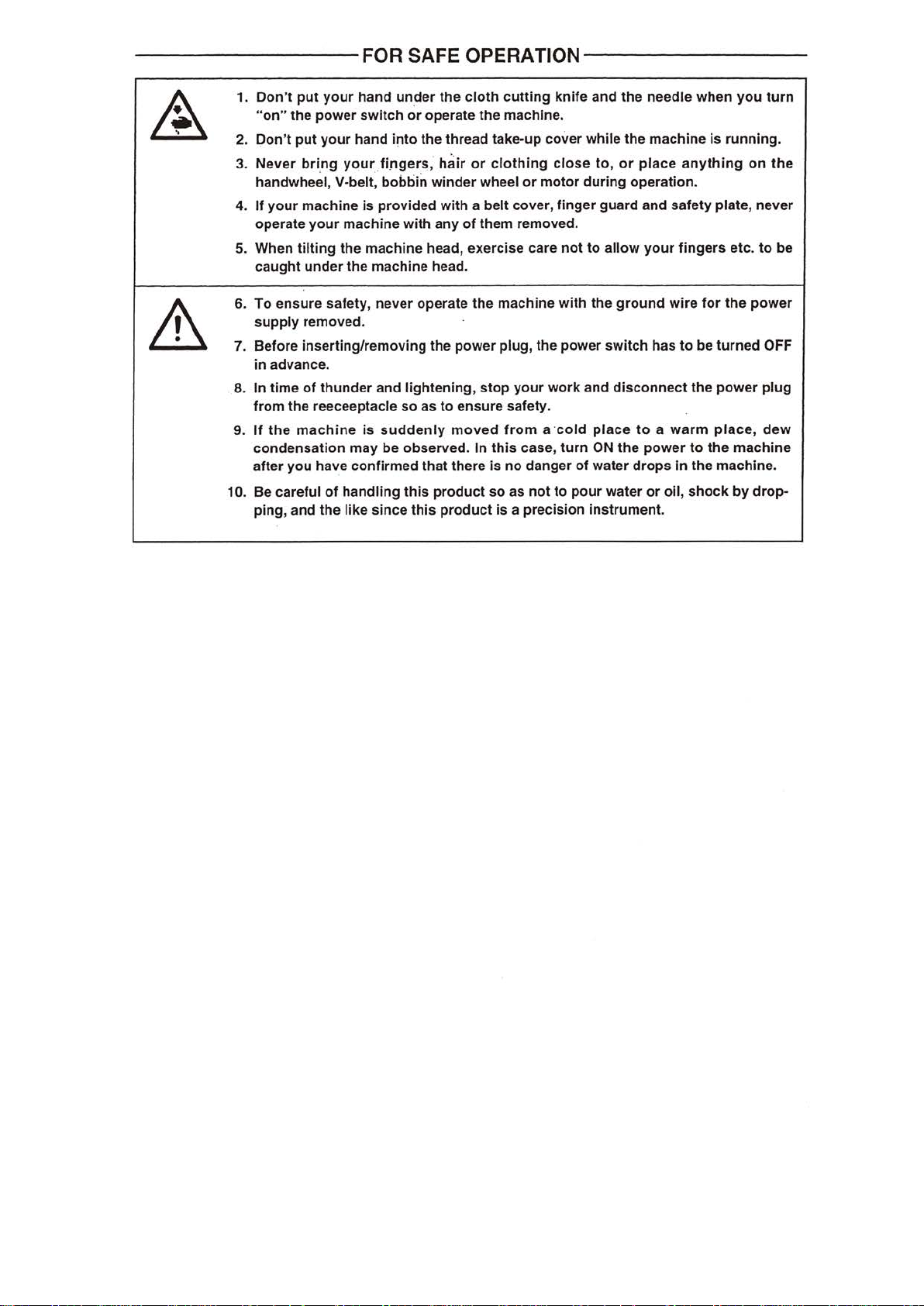
--------FOR
~
&
2.
3.
4.
5.
6.
7.
8.
9.
10. Be careful
SAFE
1.
Don't
put
your
hand
under
"on"
the
power
switch
put
your
Don't
Never
bring
handwhe~l,
If
your
machine
operate
When
caught
To
supply
Before inserting/removing the
in
In time
from
If
condensation
after
ping, and
your
tilting
under
ensure safety,
removed.
advance.
of
the
the
machine
you
hand
your
V-belt, bobbin
machine with
the
the machine head.
thunder
reeceeptacle
may
have confirmed
of
handling
the
like
or
into
fingers;
is
provided with a
machine
never
and
lightening,
so
is
sudden
be observed. In
this
since
OPERATION--------
the
cloth
cutting
operate
the
winder
head, exercise care
operate
as
that
this
the
machine.
thread take-up cover while
hair
or
clothing
wheel
or
motor
belt
cover,
any
of
them removed.
the
machine with the
power
plug, the power switch has
stop
your
to
ensure safety.
ly
moved
there
product
product
from
a ·
this
case,
is
no danger
so
as
not
is
a precision instrument.
knife and
close
to,
during operation.
finger
guard
not
to
allow
ground
work
and
disconnect
cold
place
turn
ON
the
of
water
to
pour
water
the
needle when
the
machine
or
place
and
your
to a warm
power
drops
or
oil,
you
is
running.
anything
safety plate,
fingers
wire
to
in
for
be
turned
the
power
place,
to
the
the
machine.
shock
etc.
the
machine
by
turn
on
the
never
to
be
power
OFF
plug
dew
drop-
Page 7
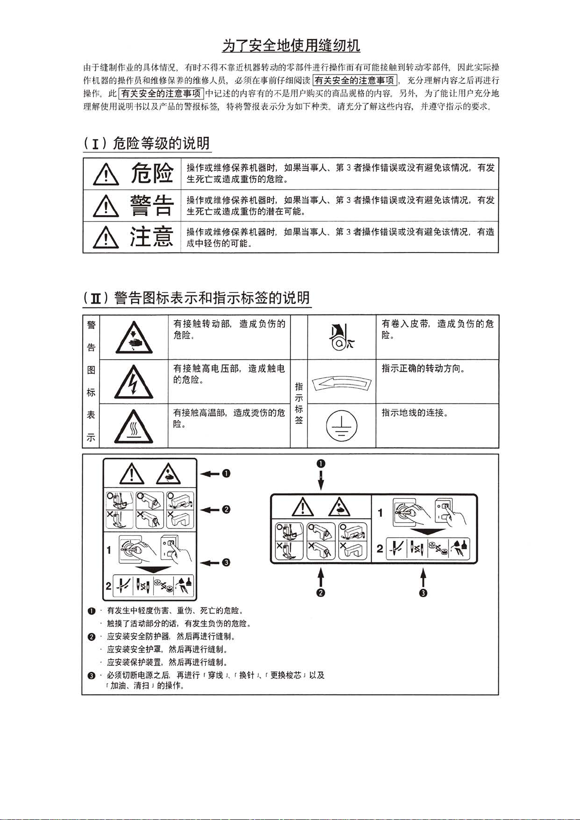
l£rtiliMi'F~(J<J~
tFVLD(J<J~tFm~••*~(J<J••Am.
~tF
.
.11t
1
fi~~~~~~-IYi
DM~Jfli3VlJl~i2.t&FJ'bfi~~H
i*t
i!fOI,
1!fut:r-1!J.7f'~:iliVLff~'i;I
J
(J<J~:g:~f4it!fr~i'Fmi1!1DJfigt~fM!i
0m~••ff•~•l
1
"Picj£(J<J~~fi(J<J7f'~.fflf'w:J~fl~im&M!~m(J<Jr:J:J~
1
H-~~.
~*t~:f1V&~?t.1-J:!IOT¥P~
fi~~~~~~-~
.
ii'tJE?tTMiS@r*J~.
1
J~'i;IJ*:g:~f!f,
1 .
~*••~wz§~it!ff
.
~9~.
.1-JT~itJtlf'Jt:?t
1f~'\1'tli
IZ5!Jit~j!,~~
!1!!
~
(J<J~;J(
.
&
&
&
w
if=.
1=1
A
1!1
~
~
*
&
ff-
fB~~
§gl±::.
1=1
1==1
~
!~
I
~
~~•••~*m~~
~9Er~@.otliiJi~tcz~
~~~••§*m~"·
~9E"C~@.nt:l:iJia<Jjft1fii]"~g
~~•••~*m~~
..
JOC
"P
$i
fJj
fi
ti
tUH
tcz~
.
fititt~l't!JI$.
a<J
tcz
~.
fi
ti~
!Poii~ff~.
~
.
~•~•A.
.
~-~•A.
~•~•A.
~
iiJ
~g
.
@.otffdJi~
IJ
ff~
.
@.ot~tl't!
@.nt~iJi~fcZ
~
.
1~
~
ff-
~
•3•~~-~~~fi~~~-~.
•3•~~-~~~fi~~~-~. fi~
•3•~~-~-~fi·~~-~.
@
fi~J\Bl:'lfi
IJ.&
o
.
.ot
ffl
iJi
fi~
fi@
aq
1iZ
~A
1~ff-iE~~~M:nr'cJ
1~ff-ii!!~~iiti
.
.
@
&
~~~
1
~~
~
~1%J
•
2
[
·~1~~~
0 .
lil~1:.1'jl$£Jlf~~-
-~m7~~-~a9~.
f)
·
Ei~~~~l!1it
·
Eil~~~~t
·
Eil~~i*t?~fl
0 ·
~'~
~t)Jrtfi~V!.ZFR.
r nc
im.
~~
~1~
?H. ~FR-ilii1H'T~iM
?.a. ~FR-MiiHT&liM
.
~FR-iliiiH'T~lM
iiH.;J
1
a9HH1=
~o
~·
~-
]
Afi:f9i.
9E"Ca9fli:
lil~1:.mffla9fli:~
-Mi1H'T
r
~li
.
.
.
J. r
~.
.
~lt
0
&
*
A 1
~~~
t
f)
.
J. r
:if~~;tt
J
tt~
~~
2[
.Jtl
-
~
~~
~
~~~~~]
t
0
Page 8
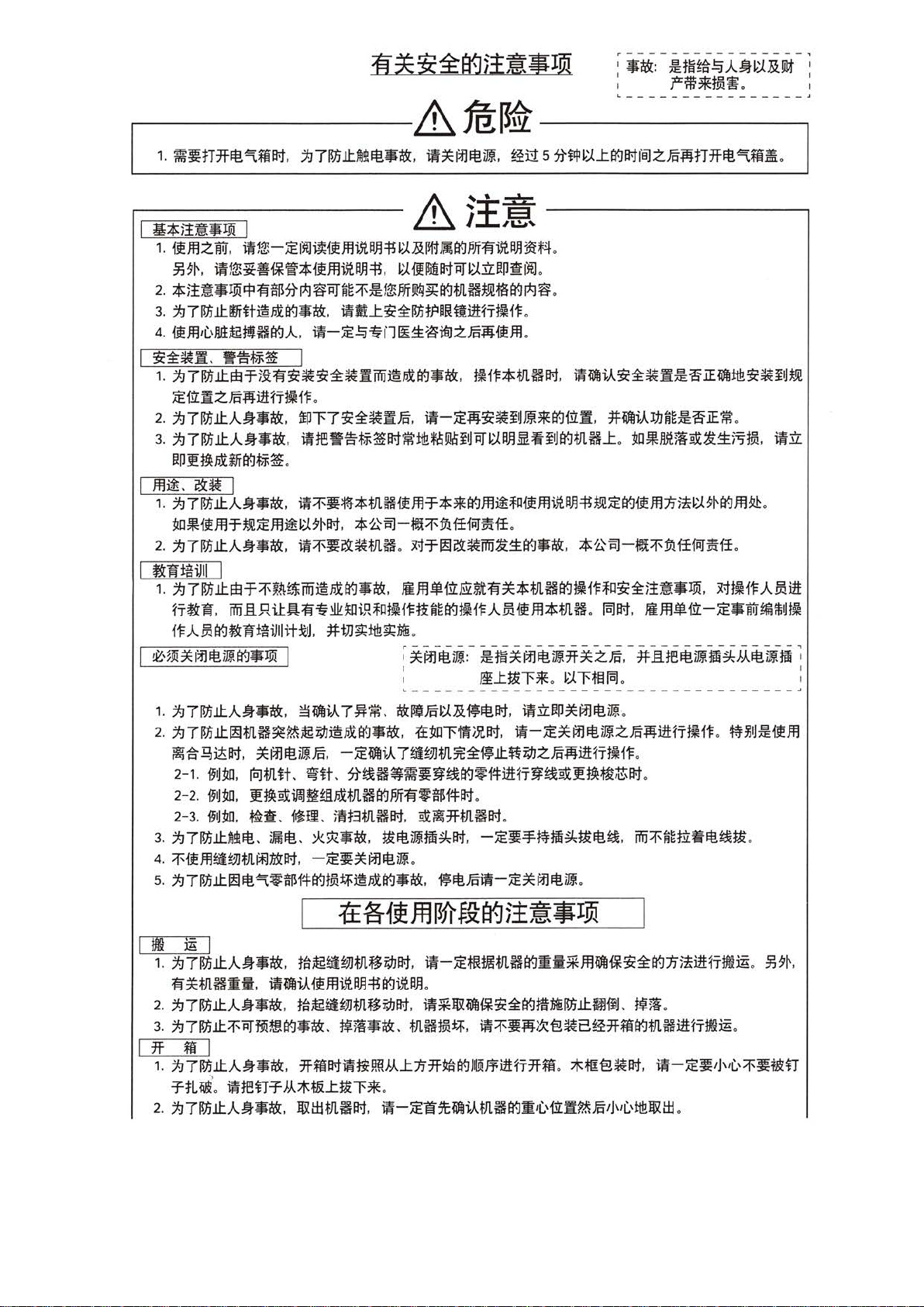
N3S3t~a9i1
$¥
Iffi
....---------
r--------------------
I
¥*1!~~n:oo
1.
~mzwr. t~1a:-~~~~{fJfJi~PJl·1H:.t~ll#~agJifffiit~aJl~n
~*·
2*~-~~~fi8~~-~-~£2AAM~agmH•mag~3
3.
~7i!Jjlt.r!fiHJ.~.fOCaglJ1C(
4.
{fffllL'.Ill1Jt£twHag.A
I
~:i:~ii-
1.~7i!Jjlt.~~mfii~~~:i:~ii~-.10Cag~1C(
~f!t~zm~ilH'T~i1=
2.~7i!Jjlt..AA*1C(
3.~7i!Jjlt..AA*1C(·
fln£~10C~ag~~
I
ml£.
&~
1.
~71l!ilt..AA*1C(·
~~{fm~•~m•~*"·
2.~7i!Jjlt..AA*1C(·
I
~llf±tSiJII
1.~7mlt.~~~-•~•.f0Cag•1C(.
ft~W. ~fiRUA:fii1f~~m~~~~-ag~~AM{fm*mH
i'I=.AMag~W
I
&::,
~
m*ffl!t!iJJag•~ I ~
I I
~-~~-~*~mm~~. ~•M
,
tifiXJ:~:i:I!JjfpPIHli1H'Tt~H~
,
~ -
~~1ff1~j::~~zm~{fJfJ
V
E-~~
I
.
·
~~7~:i:~~~
~~-15-~~HM~MMB~~~~~~agmHJ:.~~MMd~j::~m. ~~
.
I
~~~~*mH{fJfJ~**agJfJi£~1l{fffli.~
*~~-~~mawma
-~~~~mH.~~~~~~~j::ag.1C(
I
±
giJIIi.t~~J
.
*tJJ~~~~
&
Lll
~m•m&alii**mHag~~~~:i:~••~
.
*i~fltiai
I I
I
fB~t
A
~
~
~
3EE3
H~~~~~oo
.
~~*mHH. ~~~~:i:~fi£~~~~~~B-
~ -
~~~~B-*agmii.
-~-
~J:·~-.~~m~
----------,
.::e::.
------------------~
~
~~
.
.
.
.
.
P
J}~-~ag{fffl1Ji!tB~ag}fJ~
.
,
*~~--~lffWmff
.
~~
t~*~it!-i7F*.£i
*~~~--~~-
.
~m•m-~•wr~~m
.-
#13.
-
~liff!tiiJ.J.~iili
o
.
.
.
~m~.Amm
~
I
1.
~7i!Jjlt..AA*1C(
2.~7i!Jjlt.~mH•MJt£M8.fOCag*$
•&~~~
2-
1.
f§IJ~. iaJ~Jltt.
2-2.
f§IJ~. J!~dil!lflffl.IOC~JtHagJifflii*81!1=H
2-
3.
f91J~. ~~-
3.~7i!Jjlt.~lt!-~lt!-
4.
~{fm~tJJmf*l:tNH
s.
~
71l!i
lt.~
I
tm
m I
1.
~7i!Jjlt.AA~$
fi*mH:m•
2~7mlt..AA*1C(
3.~71l!ilt.~~ffi~ag~•-
,
~~i-.A.
7
~-,
1C(I!lmtUH~It!H.
, -~~
*~lt!;w.~
i~JI.
lt!~~Bi!fagt.ro~•.f0Cag*1C(·
.
.
•~~{fmm~~agm~
·
-~~~7~~m~:i:~lt.ftMzm~mft~~
~H.
~~H~~~~~JHF-J~f!I=M~
il!Jt3tJLHH
*~····It!·~~~
.
-~~*ffilt!•
1±
1aJt£~~~JL~MH.
~-~~m~MH. ~*~~1¥~:i:agm~mlt.~•-
~MlJ1C(.
. a•7HJLHH.
.
~~~ffl
mHm~.
-~H.
.
-~~~ffl~~-lt!~
~lt!mll-~*
~it~
ilt-~~lHI8mHag:mii*JfJ~1¥~:i:ag1J;!m~;:Hmili
.
a{])!~
•~~~~s~B~*magmHmftHNili
I * m I
1.
~7mlt.AA•1C(.
.:r-tL~
·
.
•~n.:r-
2.
~71l!ilt..AAlJ1C(,
*m"~~!ffiJ..A.J:n*~ag
J..A.**RJ:•~•
~I±HJlHH. ~-~1l5t~i..A.tJlHag:m~L.,m:A:Mm'J'lL'~~:±l
·
J
®l.~¥m~;:*m.
~~fln*ffllt!iJJ
·-~*ffilt!iJJzm~mft~~
'T
~H~dJ!~~;t;H
ffilt!iJJ
.
.
MM£{fJfJ
.
.
.
~~-~~It!~·
·
.
f;IY!
.
~9~.
~•
-
.
*ms~H.
tw-~~'J'
.
1
L'~~~rr
Page 9
~
I
~
( I
( n l
I
)fJl~.
~JWJ
1.
117IDJ
R~~~mH~•-~•a-t~t-J&nm~~t-Jm~
2.
1J7M.ltA.~-$:
••••·
-
ft!~lt
1!lti
1.
jJ7IDJ.ltM~ft!
~-M~il~11fll#ilf1!li~ft!~Ata1.
2.
jJ7IDJ.lt~ft!.
3.
jJ7IDJ.lt~ft!
tlB.ti
(mltlit!!
1.
jJ7IDJ.lt~iiift!.
·-:iE1Eft!iiml~~tl~tlit!!lt-J~iitf.ll.
2.
jJ7IDJ.lt~~~@•~•13!:.
(N)~~
1.
jJ7IDJ.lt~~~~ii'ii@dlt-J$$:
2.
ifJflm~ili~ag~~~~~
~li£$~P~It-Ji§i~
t~
i'F
I
I
I
M'
1.
2.
3.
t~
1.
2.
3. !it
4.
5.
6.
7.
j]Q
1.
2.
3.
I
jJ7IDJ
.ltA.~-13!:
jJ7IDJ
.ltA.~$$:
if}fj$
JWJ~~t-Jm~JWJ~
~JWJjE
JWJ~~~
1-F
~
I
jJ7IDJ
.lt~Aii'ii@dag$~.
•MooisL.
~~~
jJ7IDJ
ltA.~=~. tl~ft!•~•mB~n~.
~m.
.
!9:1
~Jl
~~~~mftftM.jJ7IDJ.lt~ffl~
~iiiMOOi!
1!JtJJ
JJ
~
l1H=r£
jJ7IDJ
ltA.~*~·
jJ7IDJ
.lt~~~ag~M@dlt-1$~
±1.1~:i:w;.lt~m~m~n~e
*OQ,~
ifJfliiil~
~ffJ~l
jJ7IDJ
iitiifffl
jJ7IDJ
jJ7IDJ
~~~It-t
••
.lt~J:I~@d~t-J.:k.;t:•~·
)Ill
I
UK
J
.11:~&~-M. ~M. ~-~~11#7~~
.11:~~-~M.
.lt
A.~¥13!:.
m-:iEifffl~iE~t-J~Jt~.
.
~~JWJ~~~JI1JJ~~~iffflAfiR~~-It-Jm~:iE~~It-JJWJ~
•~-•~a-tmft~:iE::r-~mH~M
.
i.lmft! . .:k.;k:$13!:.
~ft!
.
.:K.;t:•13!:
.
i.lmft! . .:k.;A;:*$:,
iffflft!~Atlt-tiW:f~ioJft!~At»l§JJOJ:I:*:It-J~
B~iJ:ft!~Atllei§i'E:il'1
.
~::r-~mft~ft1!lti
.
~tfiftitffii'ii@fiX~$$:,
M-:iEreit!!titlit!!.
,
~-:iEifJfl~:iEIY-J~:iE~~(~iE~l
.
~~~AV*li£mii'ii~fiXag·~
Q,~
.
.
tl~ft!ii~-
. •
:f~1E~~~mM~OO~
.
jJ7IDJ.lt~~~t-J~M@diY-1*~·
.
i!!.:f~re4m~1iU
.
~9~. J!~fu'UJJ~JltJltilt-t
.
Mm~~memmm~.
.
mH~.lt~Q,~:f~ili-B
I
~iEIY-JtJliltlfO
J UK I
~-~~7m~. •ft~i.t~~mfi.
~-:iE~~-tlH.ft!B~~~~fi~ffl-~M-~M
~nmB~.
I
J~im
.
meli£m~~~&v*li£*~·
.
ifJfl~•::r-~CttQ,~ft!iim~t-J~~c
~iEIY-J)ji]jfUijioJ~.!i!:iE00isLm~T1JO)ltlfO~i*iiiJift
~JWJ. ::r-~t.!ifJfl~~~iE~t-J~i*a-t
.
~JWJ
.
.
ii.
~9~.
30mm
t.!~
.
.
~-:iE$~it!!~:iE~tlB
-:iE-Afift!~~ll~iR~A.~~ft!iitf.ll~
~
.
. ~*·
=~~::r-~iJ:~m-~~
.
~n~~~:f~iJ:~
. •
••~~~~~••lt-1~~~.
.
·~~li£m~lt-JftM~ioJA~~~~-~
~::r-~re~mftilfmH
;.'lCf.ijf@.li.
jJ7IDJ.lt~~~ag~M@dag·~·
.
~~
-~tlBit-t.
.
· ·-
~~Jfl~~fiiDJ.lt~A~~
~-:iE~:iEJWJ~.
-
a
ilf•H-~tiB
~i.A
7!il~9J~JlfOQ,~±1.J~:i:~.lt~m~
•-:iE~f.ijft!ii.
mfi~~H~. •~~
~~ailfli£m~.~M~~
.
i!!.:r-~re~m~~mti"~
•~~:r-~~~~m
.
ftlii.
·ft~mft~~
.
·
~-:iEifffliiTt.!
.
~nmHa-t.
~ v 1f
~li£m
·-:iE~M~
.
~9~
.
.
-a.
.
H"····
.
~~7~!9Jm
·~-;:r-~~~
Page 10
I
!ttf!J~W
1.~7~ttm~~~~@~~•$.
2.~7~ttm~••~~~~-$~&~tt~••$.
3.~7mttm•M~EM~~~$$,
~~7mttA.•••· •~~~~~~••#~
~mH~~fflM~·· ~-~~M~mft~a.~M.
6.
7.~7mttA.•••·
8.
~~7~tt~~~*~••· ~~M~mft••~~c~~a~~~~~~-~
I
~ml.1'm
1.
2.
1~7mttm~Mn•~~••·
4.
~~7~ttm•~*B#~E~~~Mn~~~••· M8~~I.1'±~a~~-~~~~~:nm&~F~
6.~7~ttm•~*B#~-~~~Mnm~~••·
I
~~~~-~g. ~-~u~~mH~m~~w~*A.~~~~m
-~~~m~mft~~~~~-~~
~-~~~~~&~m*~~••#~~~•$.
tt~r.s~~*A.~iZH-r~~-~~f~I.no~tf~
i#~~Rf.Wi.:r.
f;jj•llJ..
m~i'!tf~~W.
~~i6M. ~~-~f;fl-llJ.m~i6~~fflttmM@~mftM-~M~
~ft~~ft*A.~irJIJil
~7~ttA.A$M.
~i.fi~ll.&M
tn:th
t1:1
1.t
oo
~~~zmJ}m~-r•~~mf~~w
~lA
7~WJtJL~~~~7t:i:~ttzmJ}mft
~if.
f!J~M. ~-
&tta~~~.
.
~~~~mrmm.
.
~~*B#M. ~-~·ffl*~~~~~*B#.~~~~~
*~~-~~ma~~a
m-~u•~•~•n•~~A.-~ft*~~
(
1£m:tflfat
-~~m&~W~ffl~MW~ffi~~~-H~
m-~~~~M~••~~~M
~~f,fl-llJ.
mH~~~~mnM.
J.R-~mrm•D.
.
~}A
l.
.
~7mttm•M~EM~~~~···
;ffa
.
7~~JJtJL~~i6~~:i:~ttZ.mJ}iZHi'~ff
~~~~tt~n.
t~~~7~~M:tf§Wf~mtmz.m.
.
.
~-~~~~~
.
l
~*~~•tt~r.s~~.
.
I
~7~ttlli1i~Mffm~~••
~7~ttm~Mff~~~••·
~m
.
~7~:i:ii!!~m~WJtJL.
MffM~~!H.A!J.l
MffM~ttl~il.ll
~3~~. ~-~*~7t:i:T~Z.mJ}~~-D
5"c-35
35
·
~.ff;~~~~-~m•~£11/,rtrD
.ff~ttiJi~•ffi
~~~m~ue
i~-~.ff~91JJ.1\il~m~-rifm
±
1o%~ii!!:n.
affi~~~•m.
.
1
•lii:ti&:
ill~JJ~m~WJm
•~~7ffi~M~~~zmJ}mft
·c
% -85%
.
n~M~7~~
m~tt~n. *~~-Rf.~~
l
~P(a)~J.i\il~~ffl!:iUJJtJL
.
~-~~
.
I~
£~ttl~~~
.
-
~~~-;&:~-~
m•wtn.
8.
~~.(£ r {f~J.i\ii~PJBfi.ff
~mw.
~~-~A.~. ~7~~~Jj~~m~.
~~~m:n~•~~~~A.~·~~-~~:n
~~w~nA.~~mmwm~m~.~~.ffrn~I.1'il~~•mi69~s~~J~J.1\il~~n
~~~~~fflfi~-·-·
~i\fm
.
85dB
~.:Lt.~
90d
•-~u~nA.~~mmwm~m~.
~--*·~--~"·
B
~.:.t~
J
~J.i\ii~HHf~WltJl~A.~.
.
~.ffffiffi~*~Wltll~ii!!:n•
*~~*m•~~m
~7~~fit}j~
Page 11
A!
~
H-.::>X
II
A
1.
;t)TilJj.lt),.~-$:1¥1~~.
tHfltlJJR1~:LN,#jU9JtJl~~~.
N.tllHI¥lllfH!i.
2.~71lJj.lt~MI¥1~~-~A~$$,
t~ltlJJ
.
3.
~71lJj.lt~.&:~.AtllHI¥JA~$$,
~-·-
~~-mn•~~-~.
$~~~M~
~~JJM~~~ii!f:if'~:m.':ft!!i,
····~~v~Jtmfl1.
~:if'~1e!*~$BMH~W
i'R:if'~1e!Eftl!i$~!JB~J1141,
3k~-
~RU'iili&:m$t,
t.J]JJ~:L
·-~~
v
.
~~TilJj.tt.A~*$:1¥1~~
~;JJtJl
.
a.~TilJj.tt~~•#m~l¥1•$:.
9.;t)71lJj.lt·~-#8~~·$.
*mij¥;~=f
11
.
~;t)*rr~li-T*l'.ttllH
tllH~iit~
m~tHf~tlJJ
~tJlHIIftm.
•:if'~a•~••m~~-~~llJj~H•~~·~I¥1~~~~~
n~a1•~.tt~~.
M8~1¥1~~---·~-~~I¥1-~R1.
.
.
.PJTW~iffl1
ii!i3t~l!~
.
*•~~t-~3k~~~~~.
~~~~~.
:if'~te*,
iWiJ!l~ilfJlH~W.
~:if'~iJ:
M
Page 12
CONTENTS
CAUTION BEFORE OPERATION··············
:··
······················································································· 1
SPECIFICATIONS············.···················································································································· 2
1.
MOTOR PULLEY AND V BELT .......................................................................................
2.
SETIING
3.
SETIING
UP
THE SEWING MACHINE ......................................................................................... 5
UP THE MACHINE HEAD .............................................................................................. 8
...
............ 3
4. ATACHING THE FLAT BELT .......................................................................................................... 9
5. INSTALLATION/REMOVAL OF BELT COVER ............................................................................... 1 0
SETIING
6.
7. LUBRICATION ........................................................................................................ ......................
8. HOW TO INSTALL THE NEEDLE ..................................................................................................
9. INSTALLATION/REMOVAL OF BOBBIN CASE ............................................................................
10. WINDING THE BOBBIN ..................................... y
11. THREAD THE NEEDLE-THREAD................................................................................................
12. THREADING THE NEEDLE-THREAD........................................................................................
13. REDUCTION OF SEWING SPEED AND EMERGENCY STOP.................................................
14. MANUAL .FEED HANDLE ................................................................................................................
UP THE THREAD STAND ............................................................................................. 1 0
..
11
12
..
12
.....................
.......
..............................................
.
13
13
14
14
15
15. HOW TO HOLD THE DESCENDING KNIFE .................................................................................. 1 5
16. TYPES OF STITCHES
17. THREAD TENSION ........................................................................................................................
..
....................................................................... ...... ...................... ...... ........ 1 6
16
18. ADJUSTING THE BUTIONHOLE LENGTH ................................................................................... 1 8
19. REPLACING THE KNIFE ................................................................................................................
19
20. ADJUSTING THE BUTIONHOLE WIDTH (STITCH WIDTH AND
BAR TACKING WIDTH) AND
21. CHANGING THE NUMBER OF STITCHES ..................................................................................
22. ADJUSTING THE PRESSER BAR PRESSURE ...........................................................................
23. NEEDLE-TO-HOOK RELATION .....................................................................................................
24. ADJUSTING THE THREAD TENSION RELEASE TIMING .............................................................
25. ADJUSTMENT OF THE BOBBIN PRESSER UNIT ........................................................ . : ..............
26. ADJUSTING THE BOBBIN THREAD WINDER ..............................................................................
27. ADJUSTMENT THE SPEED THANSMITIER .................................................................................
28. ADJUSTMENT OF·THE NEEDLE THREAD TRIMMER ................................................................
BUTIONHOLE
REFERENCE POSITION .......................................
19
20
21
21
22
23
24
24
..
25
29. ADJUSTMENT OF THE BOBBIN THREAD TRIMMER .................................................................. 2 6
30. ADJUSTMENT OF NEEDLE THREAD. TRIMMER HOLDER AND LIMITING PLATE ..................... 2 7
31. TIMING FOR DROPPING THE KNIFE .................................................................... : ......................
32. TROUBLE, CAUSE, AND REMEDY ............................................ ...................................................
33. STITCHING TROUBLES CAUSED BY OTHER REASONS .........................................................
27
28
31
Page 13
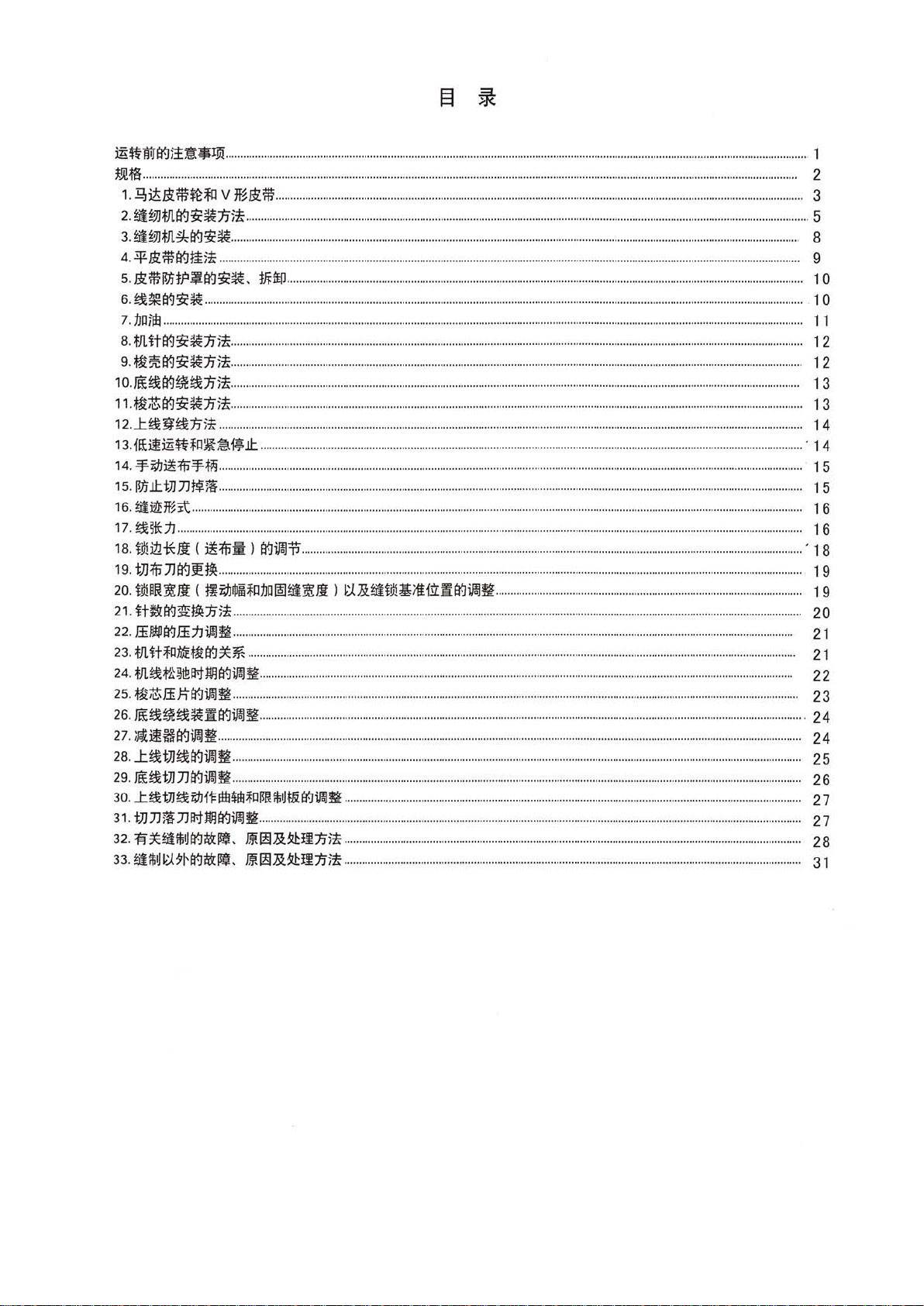
)E~WJtr..J)t~-J]i
m;f:3..........
1.
2.
3.
4 .
5.
6.
7.
8.
9.
10.Ji:i;~tr..J~~1J):Jr............
11.;Mi;lttr..J~~1J):Jr
12
13.
.................................
~itw.:m:~;fo
~~iJJVl.tr.J~~'jj):£:
~~iJJtfl~tr-J~~.
.3¥
It
iWtr..J
W.iWiJ1ifP.!Jtr..l~~-
~~tr..J~~
1JDiiE
................................................
tflittr..J~~'fj):Jr..............
W?'etr..J~~1Ji:Jr.............
.
..t~~~1J):Jr
fl£i!)E~jfQ~~-~.lt
14 . .'f.i;l)i!:f!i
1
5.1!J).lttJJJJt
16.
~~1f~it
17
.
~~*11
...........................................
18.
i9liii*Ii ( i!:f!i:ii: ) tr..Jirn:P
19. tJJ:f!i
20
21.
]Jtr..JJ!t!J:!............................................
.i9lU
!t~
Jl ( !ti;IJ~Al;fll1m~~~Ji
it~tr..J:A:t!J:!1J):Jr
22. ffi.IIWtr..Jffij)ifflfl..........
23.
tl.itjfQMf;Mitr-J;c~
24.
tfl~t'~~IJ1lmtr..liJ!Jfl
25.
W~ffi):\"tr-JiJ!Jfl........................
26.
ra;~~~~fitr-Ji,I!Jfl
27.
;Jtj!i§tr-Ji,I!Jfl.....................
28
.
..t~tJJ~tr..lifflfl
29.
Ji:i;~tJJJJtr..liJ!Jfl
30
.
...t~tJJ~i;I.Jf'
31. tJJJJliJJIJ1Wltr..Ji,I!Jfl
32.
fl';c~~Mtr-Ji!&~,
33.~iM
~.:L9~tr..li!&l!a,
...............
..........................
.......................
v
1f~Jtm
.....................
.....
......................
........
......................
1ii
:Jr
................................
tfiiff.l..............
........................
..........................
.'f.ti!i............................
~)i
......................
.....................
I=IHI*tll~rl~RiM~&tf.Jif..l~
.................................................................................................
.....
.........
......
.
. .. . ..
.... ....
. .....
.
...............
..
.......
......
.....
......................
..................
........
........................
..............................................................
..............
..............
..........
... ...
.........
.
........
........................................................
..............
......
....
.................
............
...............
................................................
........................
....
..........
.......
..........
.....
............
..........
.....
......
...
.............................................................................
......
...
........................
....
.........................
......
.........
.. .. ....................
................
......
...........
..... . .
............
....
............
.....
....................
......
..................................
......
..............
...
...............
................................................
...............
..........
...
.
....
.
....
.
.............
......
..........
............
......
.....
.........
...
..............
.......
....
...
................
.....
...............
..............
....................
..................
....................................
................
.......
...........
.............
........
..........................
........................................
.
.............................
.............................
l
~.:tR~tJ!l~iiUifitr..JiJ!lfl
......
.....................................
........
...........
.....
...........
...............
..
..............
......
................
...
............
....................
.......
........
.........
...........
....
.............
............
..........
..........
....................................
.......
...............
..
. .
..............
.....
...................................................
...
............................
..........
.......
......................
...................
.
......
. .
...
................
...
.............................
.
...
....................................
............................................
.......................................................................
JiRr!I~~.H.l1Ji:Jr
ERr!l~~!.l1Ji:Jr
..
.......................................
...................
...
.............
..........
...
......
...................
...........
.......
.............
...................
...............
.............................
................
.................
.......
...........
.
..................
........
..........
......
.........................
.................
........
..............
......
...
........
.....
........................
....................
..........
.....
...................
....
......
....
.........
......................................
.....................................
..............................
......
....................
.......
.................
.....
................
.............
.....................
.. .
....
......................
.....
..............
.............
..............
..............
.....
....
.....................
...................
..............
....
.. ..
......
..............
........................................
....
...........
...........
....
...
...........
............
.....
......
.............
............
............
....
............
....
...........
....
.............
...
....
...............................
...................................
......
...
.........................................
........
..........
....................................................................
.......
.....
..................
..........................................
..................................
.............
....
......................................
...
........................
.
. ..
......
...............
....
.....
.........................................
......
.......
........................
..........
......................................
..........................................
.
........
.
.........
...
...................
......
.
.........
....
. .
................
..
...............
......
..............
.............
..
...
..................
......
.........
..............
......
...............
........
..........
............
..................................
...........
...................................
............
................................
.................................
...............
. . .
...
............
........
...........
............
......
..............
..............
...................
........
.......
...
...............................
.........
....
........
....
........
...
...........
..........
..
. .
...
.......
...
...........
.................
.................................................................................
........
....
................
......
....................
........
.......
...........
......
.......
.....
.............
..
.......
.............
.....
.....................
.......................
.
...
.....................
. 5
..
..............................
........
....................................
....
.......................
..........
........
.........
.
......
.........
........
...........
. .
...
.. ....
....
...... ..
..
.......
.....
..............
........
...
......
........
.....
....................
...
....
..........
.............
....
............
......
.................
.............
.......
............
........
.........................
....
..............................
....
.................................
.....
................................
.............
......
...................................
.......
...................
...
..............
..............
.
...
.....
.............
............
....
... 14
..................
......................
....
. 14
......
' 1 8
..............................................
...........
...........
.......
...........
..
.....
.......................
........... ...........
.............................
.................................
....
.................
..........
......
.......
................
.
....
...............
......
.
...............................
..
.......
.
..................
....
..........
.
...................................................
.......
..................................
.....
..........
....
...........................................
1
2
3
8
9
1 o
. 1 0
11
12
1 2
13
13
1 5
15
1 6
16
1 9
19
20
21
21
22
23
24
24
2 5
26
27
27
28
31
Page 14
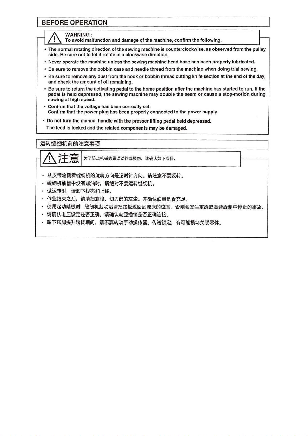
BEFORE OPERATION
_
if\
~
WARNING:
To avoid malfunction and damage of the machine, confirm the following.
.
'-=----------'
• The normal rotating direction of the sewing machine
side. Be sure
• Never operate the machine unless the sewing machine head base has been properly l
• Be sure
• Be sure
and check the amount
• Be
su
re to return the activating pedal to the home position after the machine has started
pedal
is
sewing at
• Confirm that
Confirm that the power plug has been properly connect.ed
not
• Do
The feed Is locked and the related components may be damaged.
turn the manual handle
not
to
let
it
rotate
in
a clockwise direction.
to
remove the bobbin case and needle thread from the machine when doing trial sewing.
to
remove any dust from the hook or bobbin thread cutting knife section at the end
of
oil remaining.
held depressed, the sewing machine may doubie the seam
high
speed.
the
voltage has been correctly set.
wit
h the presser lifting pedal held depressed.
is
counterclockwise, as observed
or
cause a
to
the power supply.
from
the pulley
ubr
icated.
of
to
run.
stop-motion
t-
the day,
If
the
during
r-
&1f:~
•
•
·
•
•
•
•
~
E3
I
M.$:'iW$t19JIJ~~!!JJtrl~Mt~:tflo:J£J$1f.:tlt1ilol.
~1U!JJtrtiftltt~)9:~:tJoimlf.:t.
iitm~lf.:t.
{1=~~:sRZ~.
if.lfl;g~~t&lf.:t,
mWfli.Ail!.ffii9:;E£slEWfl.
Rl'ff~m*~t&~~.
j:J71!1ill:Vtvt~m~~i'l=ii1j9im,
,1.!1~
~~m~~m~~!!JJtrt.
~ftPl'~~*ll.t~.
mfflf31irt~.
~!!JJtfl;g~~i1Ue!~t&ll&liD~'JmBfttt-JUL:Jt.
WJJ$~1JZ~.
~Wfli.Ail!iJJfftii~£slEWfli!1l.
~~~~~~~~~a.ft~a;g,
11t~i.A.ja]"f~
~)!~~~.&:~.
1H1fli.Aiftl:ii:£~3t.rE..
~
.
s
9!1J~~~-~~~~~lli~!fli;.l.t~*~.
~~nm~~~v#
.
Page 15
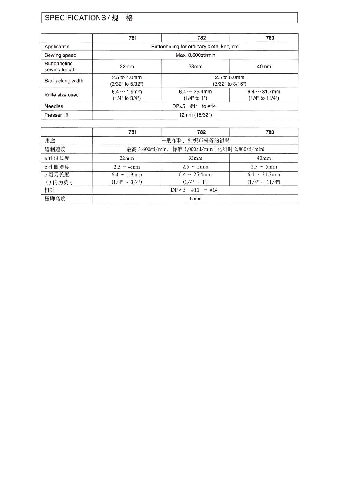
I SPEC
IF
ICATIONS I
~.m
~
781
Application Buttonholing for ordinary cloth, knit, etc.
Sewing speed Max. 3,600sti/min
Buttonholing
sewing length
Bar-tacking width
ze
Knife si
Needles DPx5 #
Presser lift 12mm (15/32")
used
22mm 33mm
2.5 to 4.0mm 2.5 to 5.0mm
(3/32" to 5/32")
6.4 - 1.9mm
to
(1/4"
3/4")
6.4 - 25.4mm
781
J'llii
tJfffirJJ3!lt
a
tLH~*.!t
b
tLH~~lt
cVlJJ*ll
()
1*1
1-J~'t
t!Ut
ffiJJ!P~Jj
ii~
3,600sti/min,
22mm
2.5 - 4mm
6.4
- 1.9mm
(1/
4" - 3/4") (1/4" - 1
-
mt;{jj*4-
.f
;j;
DPx
lfE
6
782
I
I
(3
/32" to 3/16")
(1
/4" to 1")
11
to
#14
782
<tH,q;{ji
.t4
~
3,000st
i/m
in
33m
m 40mm
2.5
- 5mm
.4
- 25.4mm
")
5 #
11
- #
12mm
I
B'HJI!D~
( 1tHat 2,800
14
783
40mm
6.4 -31.7mm
(1
/4" to 11/4")
783
sti/min
)
2.5-
5mm
6.4
- 31.7mm
(1/
4" - 11/4")
Page 16
WARNIN
~
To protect against possible personal injury due to abrupt start
after turning
G:
th
e power off and ascertaining that the
motor
of
the machine, be su
is
at rest.
re
to sta
rt
the following work
&
~~:.0:.
/.
l&
~71!Ji.i.l:.iHHt-J~i;:tJ@.6.t((.J.$:,
~
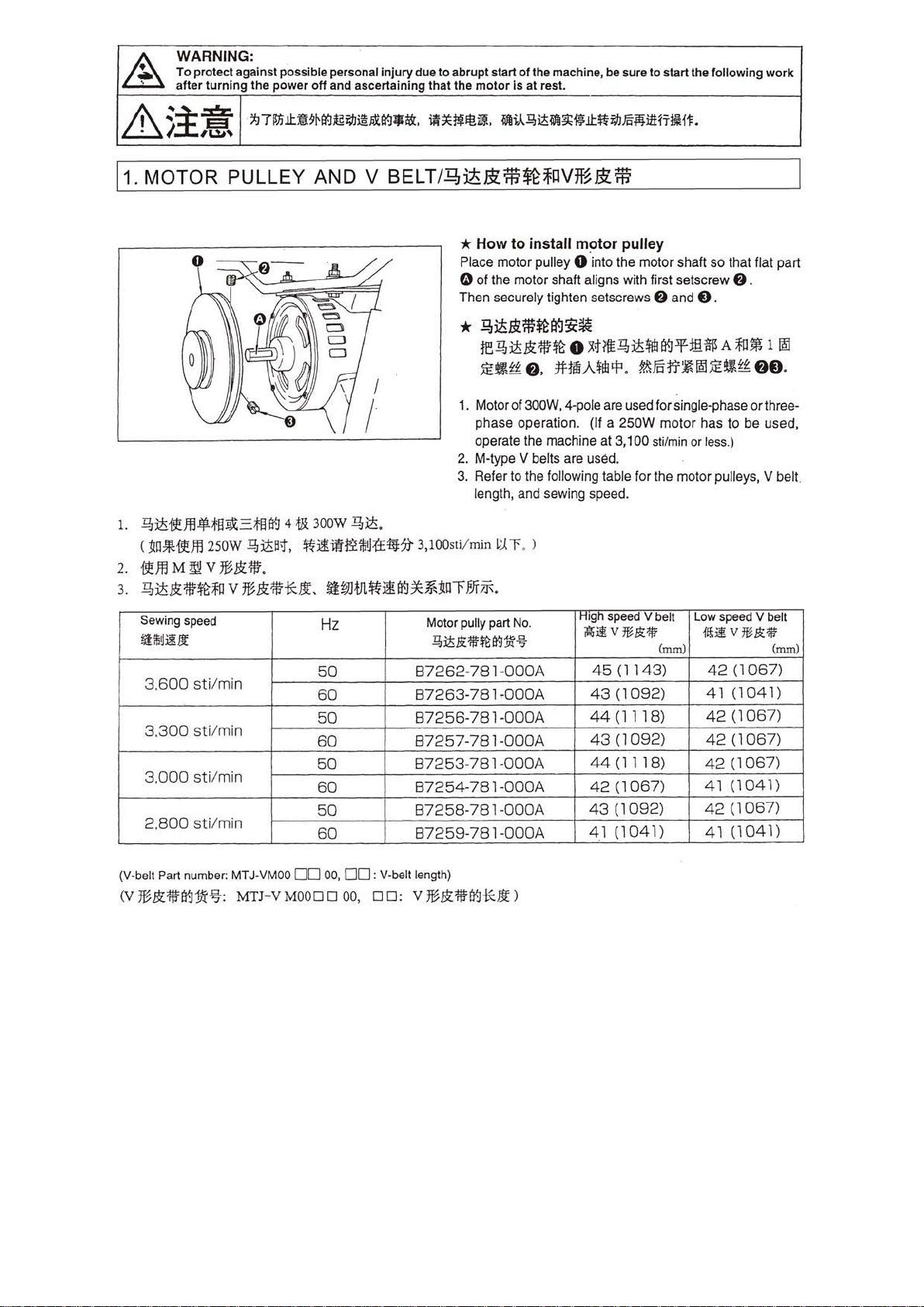
11. MOTOR PULLEY AND V
1.
~~-r!Jfl·;f§~:=;f§B3
( 1to*-r!
ffl25
0W
4lbt
300W
~:itB;f.
~lfil~~tl:(f4ij:?}
~~.
iR~J~It!~.
BELT
/Qdii
* How
Place
0 of the motor shaft aligns with first setscrew
Then securely tighten setscrews
*
1. Motor of 300W, 4-pole are used
2. M-type
3. Refer to the following table
3,100sti/min
~iA.lH~~~~.i.l:.~il!Jm-MnH'Tl~Hf.
&:iW~
~
IlVm&:
to
install motor pulley
motor
pulley 0 ·into the
iW
motor
f)
and
shaft
0 .
so
that flat part
f)
.
.!?!lti&:m~tr.J~~
re~~-•~•~~~~-~~mBA~•~~
):E~zt
f)
, 1HlfiA.rf1.
phase
opera
tio n. (If a
operate the machine
V belts are used.
length, and sewing speed.
~r
.
)
?.&Fotr~!SIJE~H~
for
single-phase
250W
motor has
at
3,100 sti/min or less.)
for
the
motor
f)f)
or
three-
to
be used,
pulleys, V belt.
.
2.
19!Jfl
M
~
V
*••
·
3.
~~--~~v*•**•·
Sewing speed
tiiilitliU£
3.600
3.300
3.000
2.800
(V·belt Part number:
(V
%.1!fi¥J:!Jt%:
sti/mi
sti/min
sti/min
sti/min
n
MT
J-VMOO
MTJ-V
~wm~lf~*••rm~
Hz
50
60
50
60
50
60
50
60
0 0
00,
MOOD
0 00, 0 0 : V
00
Motor pully part
~~Jt1tmtlj~%
87262-781-000A
87263
87256-781-000A
87257-781-000A
87253-781-000A
87254-781-000A
87258-78
87259-781-000A
: V-belt
le
ngth)
*•11fi¥J¥:!Jt)
-781
.
No.
~OOOA
1-0
00A
H1gh
speed v belt
~]!V*.!t'llf
45 (11
43
44 (1118)
43
44
42
43
41
(1
(1
(1
(l
(1
(1
43)
092)
092)
1 18)
067)
092)
041)
Low spee
~ifV%Jt'lif
(nun) (nun)
42
41
42
42
42
41
42
41
d V belt
(1
(1
041)
(1
067)
(1
067)
(1
067)
(1
041)
(1
067)
(1
041)
067)
Page 17
0
*
How
to
install V
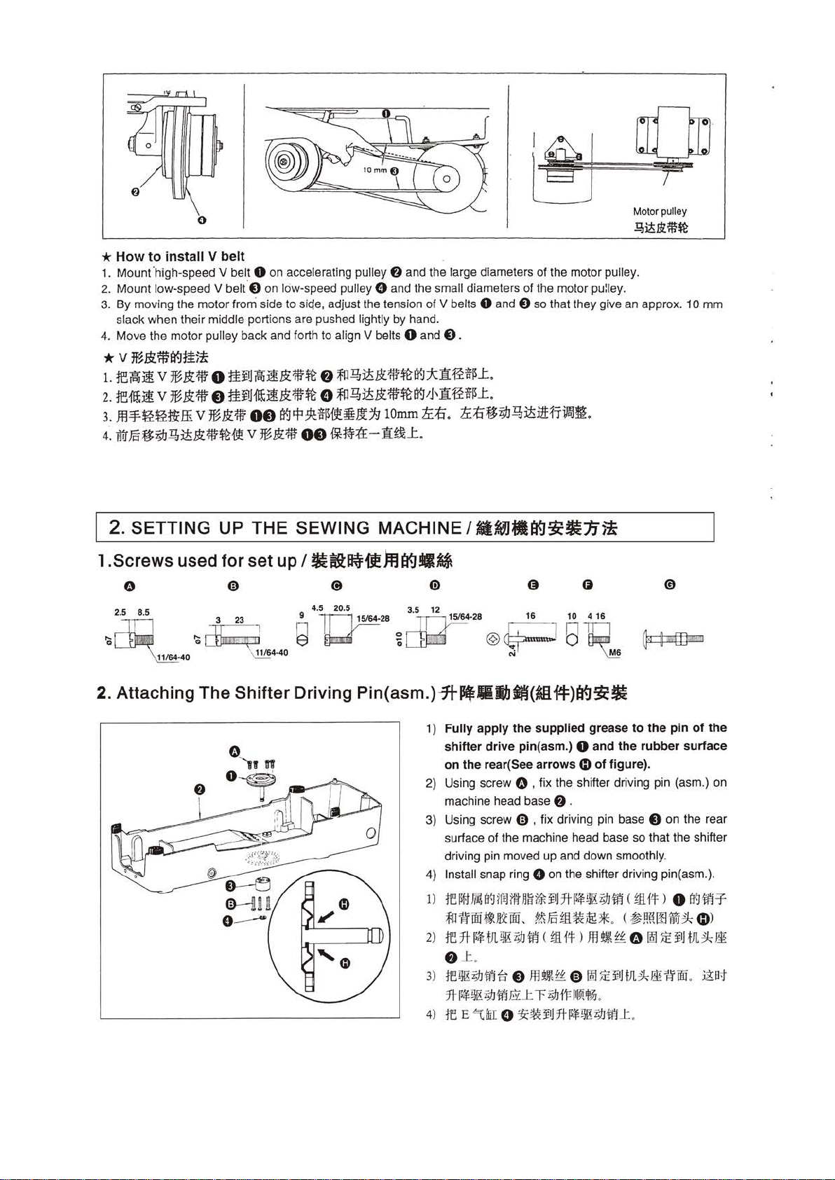
1. Mount ·high-speed V belt 0 on accelerating pulley 0 and the large diameters
2.
Mount low-speed V belt.O
3. By moving the
sl
ack
when their middle portions are pushed lightly
4.
Move
the
motor
* v
~.ftfji
ag
1.
ffl~ji
2.
re-m;j! v %&:111
3.
ffl~
4.
li1IFcf$;1JQ,J;5Jt1!1~~
v
M&:1!1
~ ~.
£rtffi
belt
on
low-speed pull
motor
from side to siqe, adjust the tension
pulley back and forth to align V belts 0
}ti!
0
tti!Jitfij!Jt1f1~
e
ttiJJ{ij;j!Jt1f1~
v %
&:
*
00
89
!fl
:9i!:
v
%&:7W
00
ey
f)
~l?JJ;5&:1!1~89:X1I~~~J:.
o
~l?JJ;5&:1!1~89'J'1I~~~_t.
~~~~It
~M=:(E-1I~L..
9 and the sma
of
by
hand.
and
1iJ
1
Omm
tr:
ll
diameters of the motor pu:ley.
V belts 0 and 0 so th
0 .
1:i
.
tr:
1:i
f$
;1J
l?7J;5iiHrifol~.
of
the motor pulley.
at
they give
Motor pulley
l?!i!.rtm$t
an
approx. 10
mm
2. SETTING UP THE SEWING MACHINE I
l.Screws
0
2 5 8 5 4.5 20.5
. . 3 2.3 9
'a
2. Attaching The Shifter Driving
used
'&
~
-40
for
set up I
~4-
Q
40
~fti~{t)@ag•ij\
3.5
lfl
~28
~
Pin(asm.)-7t~lllbM(iiH4:)H9$:•
12
~
i
[}}D
1)
2)
3)
4) Install snap ring
1>
2)
3)
4)
8~MH9$:Jtn~
28
Fully apply the supplied grea
shifter drive
on
the rear( See arrows C)
Using screw 0 , fix the shifter d
machine head base
Using screw 0 , fix driving pin base 8
surface
driving pin moved
16 10
@~Bid
N -
pin
(asm.) 0 and
416
~
se
to
the
of
figure).
ri
ving pin (asm.) on
the
rubber surface
0 .
of
the machine head base so that the shifter
up
and down smoothly.
0 on the shifter driving p
re~u~a9t
~'Itoo~~wL
re
f)
rerJIK;tJlf!~
7t
~
re
f
ilntn~~~IJ:Jt~!MK;IJiJ
?1.\Fo!ll.~~*
::1t
!!*
tllll!Uro
.1:
.
o
rJtK
Z9J
m
EY:
E ~
flii o :t<~~
WI < !11.1!f:
mt~£-£ CDIM~~~Jtll;'k~~oo
_t
r
)Jfl
Z9JtFJ®i 4%.
J7t
~rJIKZ9Jli!JL.
(
!JHt:
· ( ~~~OOTilT~
~
1-£
0
1M
.
pin
on
the rear
in
(asm.).
> o
09iiT-
dD
~
~HJl
.
of
the
>
;'k
mt
)!at
Page 18
3. lnstlllng
Transmitter(asm.)And
Shifter Base(asm.)
l.fl~ft(~f-1:)~71-~ft·(~f-F)tf.J:it.
1)
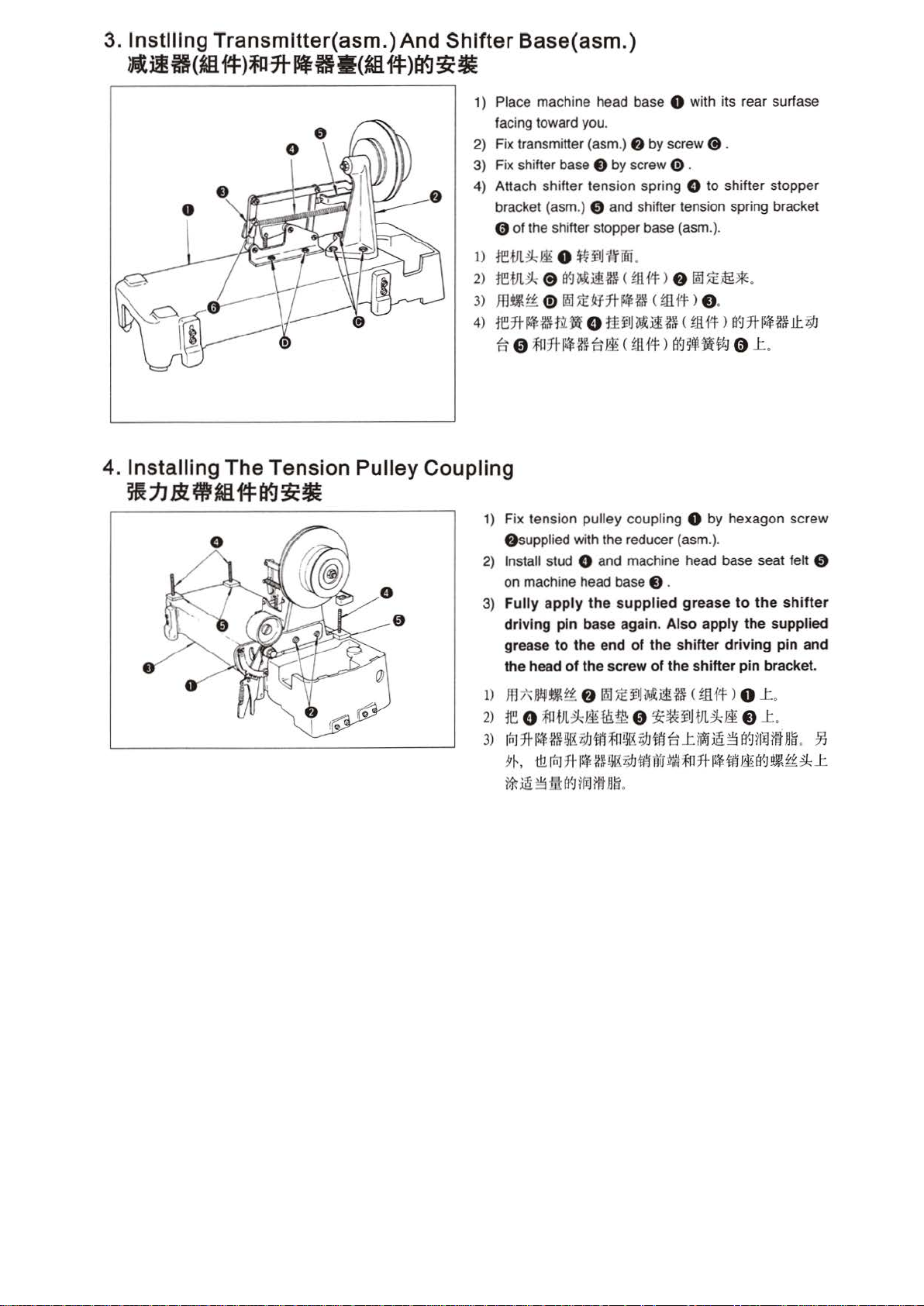
Place machine head base 0 with its rear surfase
you
facing toward
2)
Fix transmitter (asm.) 8 by screw
3)
Fix shifter base 0 by screw (!) .
4)
Attach shifter tension spring 0 to shifter stopper
bracket (
asm
.
(j
.
.) 0 and shifter tension spring bracket
0 of the shifter stopper base (asm.).
1)
te-tJl~~
2)
rem~
3)
mmx-f:
4)
re7t~t.~tJL~
~ 0 ~lJH~2Hi~
0
$UIJ·IfUfi
Ci
B<J~.!.ilU~
0
m=~~M7t~~
o
.
< ffi.{lt)
c
mft
tt~J~JI~
<
gJH4
>
8
121~it!BIC
> o.
c
mftt
a9~f-~~
.
>
B<J7t
llil!~.IL
0 ..t.
4. Installing The Tension Pulley Coupling
~jJBl.~~f-Ftf.J:it.
1)
Fix tension pulley coupling 0 by hexagon screw
& supplied with the reducer (asm.).
2)
Install stud 0 and machine head base seat felt 0
on
e
0
machine head base 0 .
3)
Fully
apply
dr
ivi
ng
pin base again .
grease to
the head
of
the
the
the
end
screw
supplied
Also
of
the
of
the
grease
apply
shifter
shifter
to
the
the
driving
pin
supplied
pin
bracket.
~
shifter
and
1)
Jtlt\jj!p~£-f:
2>
re
o
3)
inJ
7ti~Mi00:iY
*·
&inl7t~U~~M00.~7t·M~B<JS~~..t
tt-
if!~
f)
~~~J~ilR~
;trHJt~ii
ill:
En.~ 0 :tc~~Jm~~
J
.mffi~HK
;
Mil!
(
i<J
71IJ
rtHI!
.
<
tJHt:
i!..t?iti
> 0 ..t.
o ..t.
~§
B'~tfiJffl
nli
.
;'i'j
Page 19
5. Installing The Machine Head Base (asm.) 8DlRl
(llf-I:)B(]gc~
6. Installing The Motor I
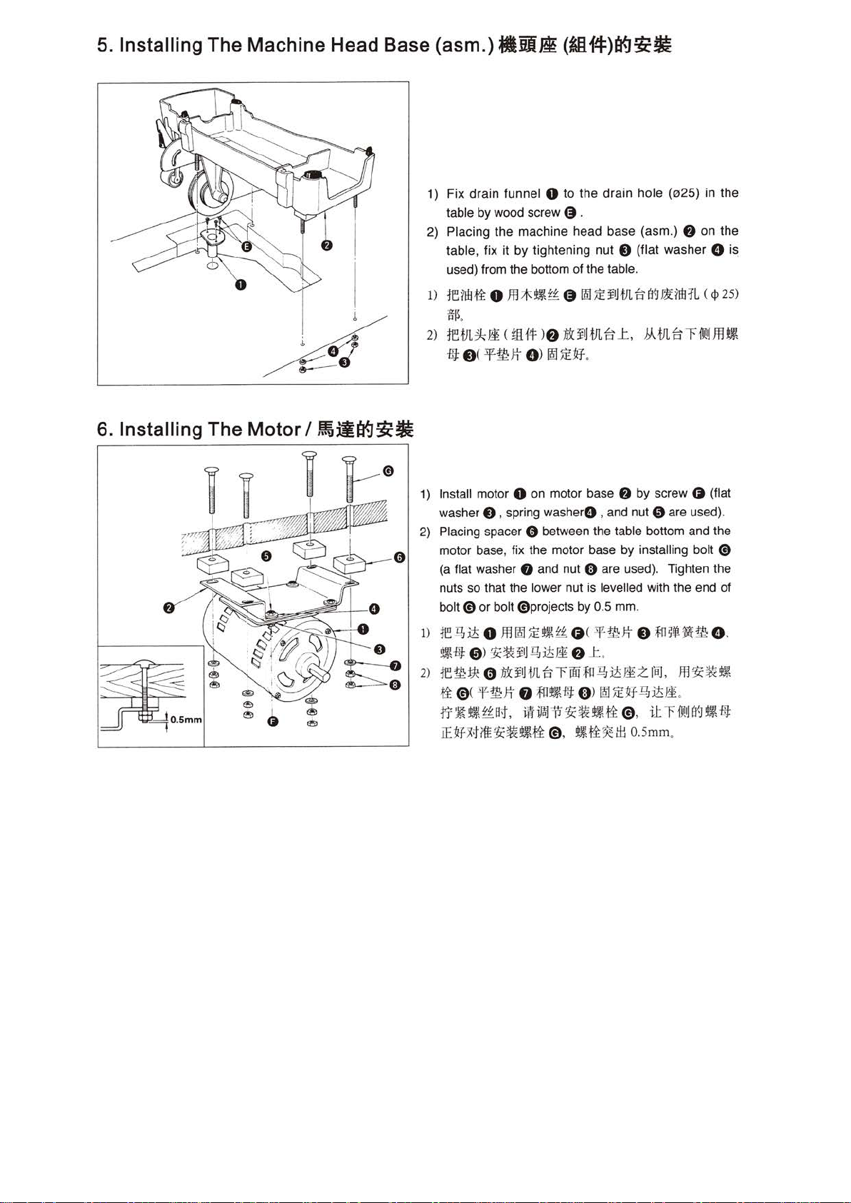
1) Fix dr
table by wood screw
2) Placi ng the machine head base (asm.)
table , fix it by tightening nut
used) from the bottom of the table.
1)
rerm.fi
}}~.
2)
retJL~~
-BJ:
e<
,~)lB(]gc~
1) Install motor 0 on motor base
washer
2) Placing spacer
motor base, fix the motor base by installing bolt
(a flat washer 0 and nut 0 are used). Tighten the
nuts so that the lower nut is levelled with the end
bolt 0
ain
funnel 0
o
m*t~z-f:
U.H.f!f:
-'¥-mJt
8 , spr
to
the
~
.
@
f9:1J:E¥1HJL
)
f)
$:¥1JtJL
G)
f9:J
J:E~.
in
g washerO , and nut 0 are used).
0 between the ta
or
bolt 0 projects by 0.5 mm.
dra
in hole
(0
25)
f)
8 (flat washer 0 is
8-tr-.JJl:M:r
~
J:
,
J.AVL
f)
by screw 0 (flat
bl
e bottom and the
L <
ftrfJ!
in
the
on the
<P
25)
IJ
Jfl~
0
of
~
fl+
mm
1)
rei& ito m
~ff]:
0 )
2)
rem*
ti
@(
~-~#~, -~~~··.fi@.
.iEM-Miff~~~.fi
IQI
Ji:!Jlllt-t-
o<
SJZ-mJt
~~¥1JI!.J;)t~
0
nj
¥U
tJL
-'¥-fl!:Jt
0
f)
.t
..
ft r mnn
."f11~-I±J:
@,
.!JJ
(f))
!U!Ji:M-Q,it~
!Jlllti~tl:l
it
e
to~!f!~~
Ji
z
raJ,
m ~ ~
.
ftTOOIY-.J
O.
Smm
.
e,
t~
••
Page 20
3. SETTING UP THE MACHINE HEAD
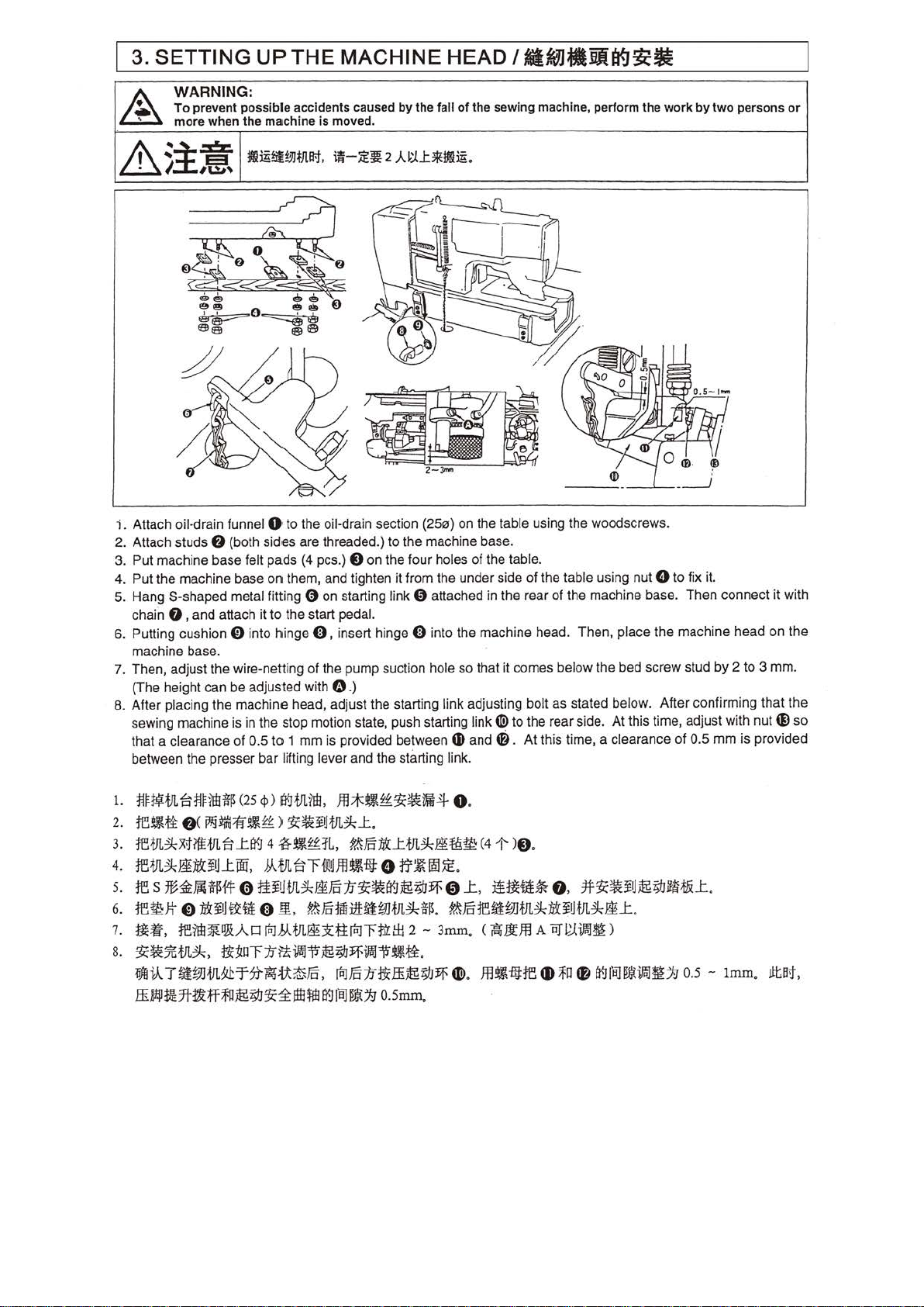
WARNING:
To
preve
nt
mo
re when the
possible accidents caused by the fail
machin
e is moved.
of
the sewing machine, perform the
/ilktnltifHf.J~-
work
by
two
persons or
i.
Attach oil-drain funnel 0 to the oil-drain section
2. Attach studs
3. Put machine base felt pads (4 pes.)
4. Put the machine base
5. Hang S-shaped metal fitting 0 on starting link 0 attached in the rea r of the mac
chain
6. Putting cushion
machine base.
7. Then, adjust the wire-netting of the pump suction hole so that it comes below the bed screw stud by 2 to 3 mm.
(The height can be adjusted with
8. After placing the machine head, adjust the starting link adjusting bolt as stated below. After confirming that the
sewing machine is in the stop motion state, push starting link
that a clearance of 0.5
between the presser
1.
t.l~1¥tn.
2.
fe!lti
3.
retn.~xtff£tn.B-
4.
te1JL~RlUHU..tW,
s. res
6.
te~Jt 0 $:~U~iti
7.
~lr.
8.
3i:~%.tJL~.
liJlli:A
ffi.&!Pt.i
f)
(both sides are threaded.) to the machine base.
8 on the four holes of the table.
on
them, and tighten it from the under side of the table using nut 0 to fix it.
0 , and attach it to the start pedal.
0 into hinge 0 , insert hinge 0 into the machine head. Then, place the machine head on the
0 .)
to
1 mm is provided between
bar
lifting lever and the starting lin
B-~~71t!ffH25
f)
(
PJ§~:ff!'H)
%~J~J~fftH4'
tfl7lt!*i!EtJdJ
Tt;ttm
.tflA
7t
£Uf~
<i>)
~tJ!.illl,
1C~¥Utn.~..t
..tt¥.1
4
~~££:tt.,
bl-tJl.B'"ffJllJJfl~fl1:
0
1t~um~~Fc:1f3i:~t¥.J®;tJYf
0
!E,
rt:l
b\.tJL~~ttrliJ""Fnrtti2
~~"f:1f~-~j§;IJYf·~~~
IFf?t~~::5Fo,
i§;IJ
1C:i:
Jfl*~££1(~ttifi4
?tFo:~&..ttn.~mns~
?tFc111luUl~JtJL~ff~
rt:!Fo/J~ffij§;IJ~
!Ill~
t¥.1
fBJ
~:1;
.
(2513)
0
17~~~.
.
-
3mm
o.
smm
.
on the table using the wood screws.
hi
ne
base. Then connect it with
CD>
Q)
and m.
k.
to the rear side.
At
this time, a clearance of 0.5
At
this time, adjust with nut ® so
mm
is
provided
0.
<4-t- )8.
0
..t,
it~~*
?tFotet.iU7J.tJL~$:~U.tJL~Ji..t.
. c
il1liJ.tffl
~
.
ffli,f!J:te
o.
*3i:~¥U®;tJ~;.t&.t.
A
iiJIW~~o
~ ~
f)
t¥.lfBJ~·~1J
0.5
-
lmm
•
.lltB1,
Page 21
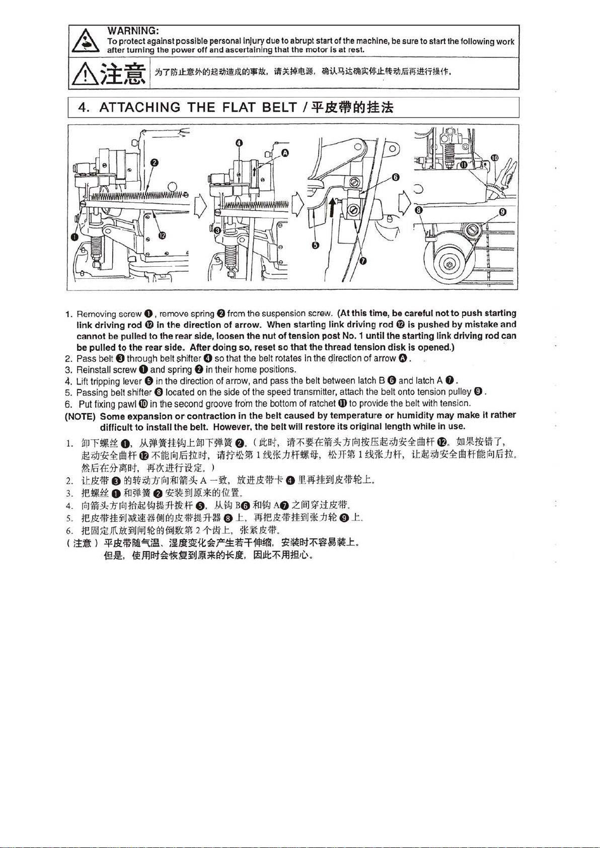
WARNING:
~
To
after
protect against
turning
the power
poss
ible personal
Injury
off
and ascertai ning that the
due
to
abrupt start
motor
of
the machine, be sure
is
at
rest.
to
start the following
work
&
:i::a:.
/.
l&
4. ATTACHING
1. Removing screw 0 .
link
driving
cannot
be
2. Pass belt
3. Reinstall screw 0 and spring
Lift tripping lever 0 in the direction of arrow, and pass the belt between latch B 0 and latch A
4.
5. Passing belt shifter 0 located on the side of the speed transmitter, attach the belt onto tension pulley 0 .
6. Put fixing pawl
(NOTE)
1.
2.
3.
4.
s.
6.
( 5!1: l
be
pulled
pulled
to
8 through belt shifter 0 so that the belt rotates
Some
difficult
fff!r~~
~7,;1J~~!It!fi
?'!.\
§
U&:'ttr
te~f'f'
[ti]~~]J[ti]ffil§tfJ!lHtrttff
m&:'ttrtt~J~J£~~1J!~B"Jl:t'ttrtt:rt~
re~J£~•·~~B"J•a•2~C_t,
o .
:(£
5}-
~B;f,
8
a!J~7,;1J1J[ti]l!JiWfk
o
lll~••
-¥Jtmllll9:1~.
@~.
.:.t.J71ffjlt~~~I¥J~id:J~I£tr.J$t&.
..
THE
remove
rod
4»
In
to
the
the
rear
tiD
in the second groove fro
expansion
to
install
.M.~JfttfJ;J_tfff!r)••
tl
~8[ti]~tt",
-Ill
?X
o
fiJfiM~~~i!
spring
the
direction
rear side,
side. After
or
contraction
the
belt. However.
:ilHr~
J£
~~¥UJH.Jlta:Jwll
)HJ.t~it~f'~~
FLAT BELT I
f)
from the suspension screw.
of
arrow
loosen
doing so, reset
f)
in their home positions.
in
o. < lltot,
m~~-lH*hff~e.
. )
A -J.t
f)
,
J
mB~tt-.l'*ll·
ntil!&:~tH~
.
.b\tfJ B0l!Jt1J
e
_t,
••&:•
-T
~*~~il.J..
. When
the
nut
of
tension
so
that
·m
the bottom of ratchet
the
belt
caus
the
belt
will
llt~~1£~~1J[ti]ti(ff~7,;1J:ti2~!1t!ff
0
A
f)
lllte&:{fttflJ*h~
.
1113~.
~~M:f~~~J:
~Jlt:fJflf§.iC.'.
~i.)..~~~~~li:.*tid:J~~i1H'Tf~ft
-¥.Blma9~~
(At
this
time,
be
careful
starting
!I!.fllf£¥
Zf8J~:i1&:'ttr
link
driving
post No. 1
the
thread
In
the qirection
ed
by
temperature
restore
•HMl~*hff,
1J&:'ttf~
until
tension disk
of
6)
to provide the belt with tension.
its
original
_t.
.
0
_t
.
.
rod
the
arrow
or
length
4f)
is
pushed
starting
is
opened
0.
humidity
while
U~7,;1J$2~!1t!fi8[ti]§tt
•
not
to
push
by
mistake
link
driving
.) ·
f).
may
make
in
use
.
fl
. :tm*ti(ftiT,
it
starting
and
rod
can
rather
.
Page 22
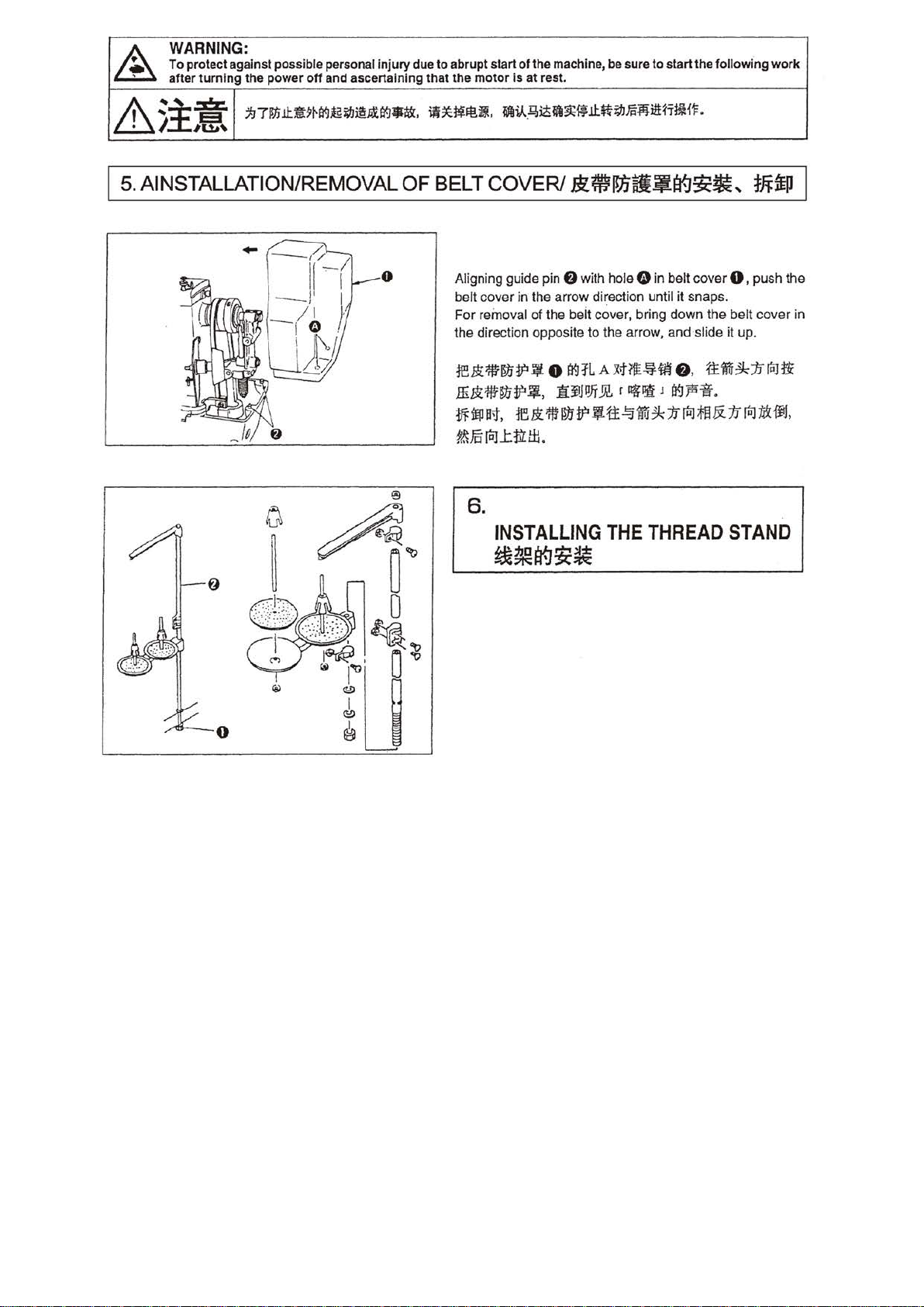
A
WARNING:
To protect against possible personal
after
turning
the power
off
and ascertaining that the
injury
due
to
abrupt start
motor
of
the machine, be sure
is
at rest.
to
start the folfowi.
ng
work
&~i:Xr.
/,
liS~
5.
AINSTALLATION/REMOVAL OF
;97J!Jill:ll?~tr.Jt£~@~rt-.~•$.
ii*~~ll.
BELT
0 Aligning guide pin 0 with hole 0
belt cover in the arrow direction until it snaps.
For
the direction opposite to the arrow, and ·siide it up.
1eBi1!Hn1?1J
ffi~*~1f~.
!If
?&
li.ff!V-
.
B;~Wt~ifll:*i~m~itt~'Tl~Ht
COVER/
removal of the beit cover, bring down the belt cover in
ir:P
at,
re ~ 11ntr
Fc
iaJ
..
t.tll:
~~~mtlf!~~~
0
99JL
AX;ffi~ff
H~~~r~~Jfl9~~.
1?
~tt
..!:j
f.i
tl:l
.
6.
INSTALLING
t&~~:tc~
THE
.
..
mlfll
in
belt cover 0 , push the
8 ,
ttim~:Jr(I;Jtii
~
1i
fiiJ
~~
li
1i
flil
THREAD
STAND
tit
ijJ,
Page 23
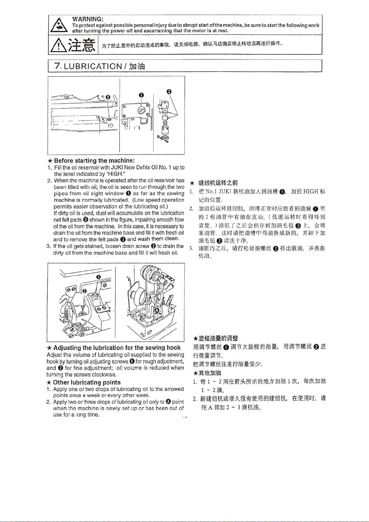
WARNING:
~
To
after
protect against possible personal injury due
turning
the
power
off and ascertaining that the motor is at rest.
to
abrupt start
of
the machine,
be
sure
to
start the following work
&
~~.:0:.
/.
,F{E
;tJil!!i.i!::«~~tr..JitfiJ.Jl§.nilt:J'"t&:.
..
7. LUBRICATION /
~
. . . ..... ·-- H
fc-
--- ·
- · . -· ..
.
r-
... -----
fU\
~J;
~
- e
1.J01fE
0
~
~~~It!.~.
ilj
~
E)
~
* Before starting
1. Fill the oil reservoir with JUKI New Defrix Oil No. 1 up to
the level indicated
2. When the machine is ·operated after the oil reservoir has
been filled with oil, the oil is seen to run through. the two
pipes
from oi.l sight
machine is normally
permits easier observation
If dirty oil is used, dust will accumulate on the lubrication
net
fe~
pads & shown
of the oil from the machine. In this case, it is necessary to
drain the oil from the machine base and
and to remove the felt pads
3. If the oil gets stained, loosen drain screw
dirty oil from the machine base and fill it will fresh oi
the
machine:
by
"HIGH."
window 0 as
l
ubrica~ed.
of
in
the figure, impairing smooth flow
far
as
(L
ow
speed operation
the lubricating oil.)
fill
it with fresh oil
e and wash them clean.
f)
the
sewing
to drain the
l.
~il-B,~~~i*.i!:~l>flm¥li1H'THH~
1.
re
No
.1 JUKI
t
ti't:l
f
.ll~
2.
1JD7l!JJ5jg$UUJHJ
i't:I2MillJW~WM~ft~
r
~Hlt
8Mft.
rru.:e
ff!.
3.
M E
~zFc, -~~-illl
i'ffJlntltJDAli!JillJ
.
L,
ilf.Jtl'tiE
> 1m
!l!!
T z
Fc
~
fJFt'¥
~~
~rentJM~~illJ
e
m
m-T~
.
•*&*WM
.
.ft 0 . 1J
'
fil·nt~imfti!Ji
.
<~Wjg
i!J
nn
-a&i't:l,
1m
.:e
Ui!J
HIGH
l!J
@ 0
ft~
·3M
tE:
e
t-.
,
*~
illl.
#.iff
:f
j;
m.
m
~
.til'
T ~
tJUrtJ.
*
ME~iltl:l:a9i?alfl
*
Adjusti
Adjust the volume
hook
and
turning the screws clockwise.
*
Other
1. Apply one
points once a
2. Apply two
when the machi ne
use for a long time.
ng
by
turning oil adjust
f)
for
fine adjustment;
lubricati
or
or
the
lubrica
of
lubricating oil supplied to the sewing
ing
sc rews 0 for rough adjustment,
ng
poin
two
drops
of
week
or
every other week.
three drops of lubricating oil only to Q point
is
newly set up
tion
for
the sewing hook
oil
volume Is reduced
ts
lubricating oil to the arrowed
or
has been out
when
m~~~~o~
1
-T~iiH~~
re
tJf
* Jt
1.
'ilt
2.
~~WJ-t!LY.X:1~.9di1f~
of
.
i) ~
~itt.ID.
f1E
1Jn
Htl
1 - 2
Ja]fi:~~F,JfffiB<Ji&:/J
1 - 2
~.
tEA
~~:bD
~* ~~
rr¥m
:fit~
2 - 3
~tf1.7Hl
~illl
~. m~~
~!?.
:b07itl
ffl
~~WHJI., {E~Jfl
.
~~ e
l1X,
m
'ilt~
:JJ
D7fll
B
;f,
i\1
Page 24
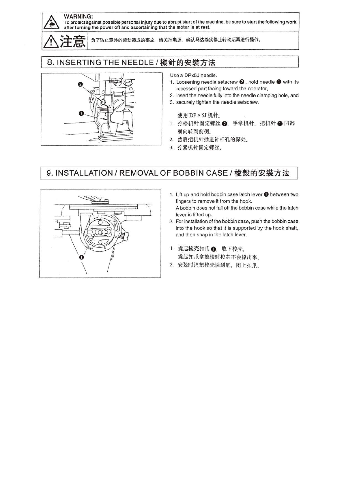
WARNING:
~
To protect against possible personal injury due
after
turning
the power
off
and ascertaining that
to
abrupt start of the machine, be sure
the
motor
is
at rest.
to
start the following
work
&
.:-i::e:.
I
;T£,.
jJ71!Ji.I1::;9~1Y-J~tJ:Ji§l£tr..J$i\t.
8. INSERTING THE NEEDLE I
in~~lt!ill.
~i.A.~~~~~.ItfiiJJ.fi'i¥}i1Hi't~H~
#l~I¥Jgc~1,1)~
Use a DPx5J needle.
1 . Loosening need
recessed part facing toward the operator,
2. insert
3. securely tighten the needle setscrew.
1.
2.
3.
the
~Jfl
DP
rrtktJL~too~~£~
~(I;]$U
~ftiffi.VL-tHffi:ilHH=flla<J~~.
ft~tll.ft~~U{£t
le
setscrew
needle fully into the needle clamping hole, and
X
SJ
.fJL
~t.
e .
UBIJOOJ.
.
9. INSTALLATION I REMOVAL OF BOBBIN CASE I
1. Lift up and hold bobbin case latch lever 0 between
fingers to remove it from the hook.
A bobbin does not fall
is
lifted up.
lever
2.
For installati
into the
and then snap
on
of the bobbin case, push the bobbin case
hook
so
that it
in
the latch leve
.
f)
,
ho
ld nee dle 0 with its
-¥~mtt.
remn
o
l!!l~
~~I¥Jgc~:Jj5~
two
oH
the bobbin case while the latch
is
supported
by the
hook shaft,
r.
1.
mm;~7UoJR
mm;toJR~:IitE~ntt~~'~'4?t~tti*
2.
~~B;Jiiffi~ll:tifiiiJJL\:,
o.
Jf
~cf~n.
.
I
~J:toJR.
Page 25
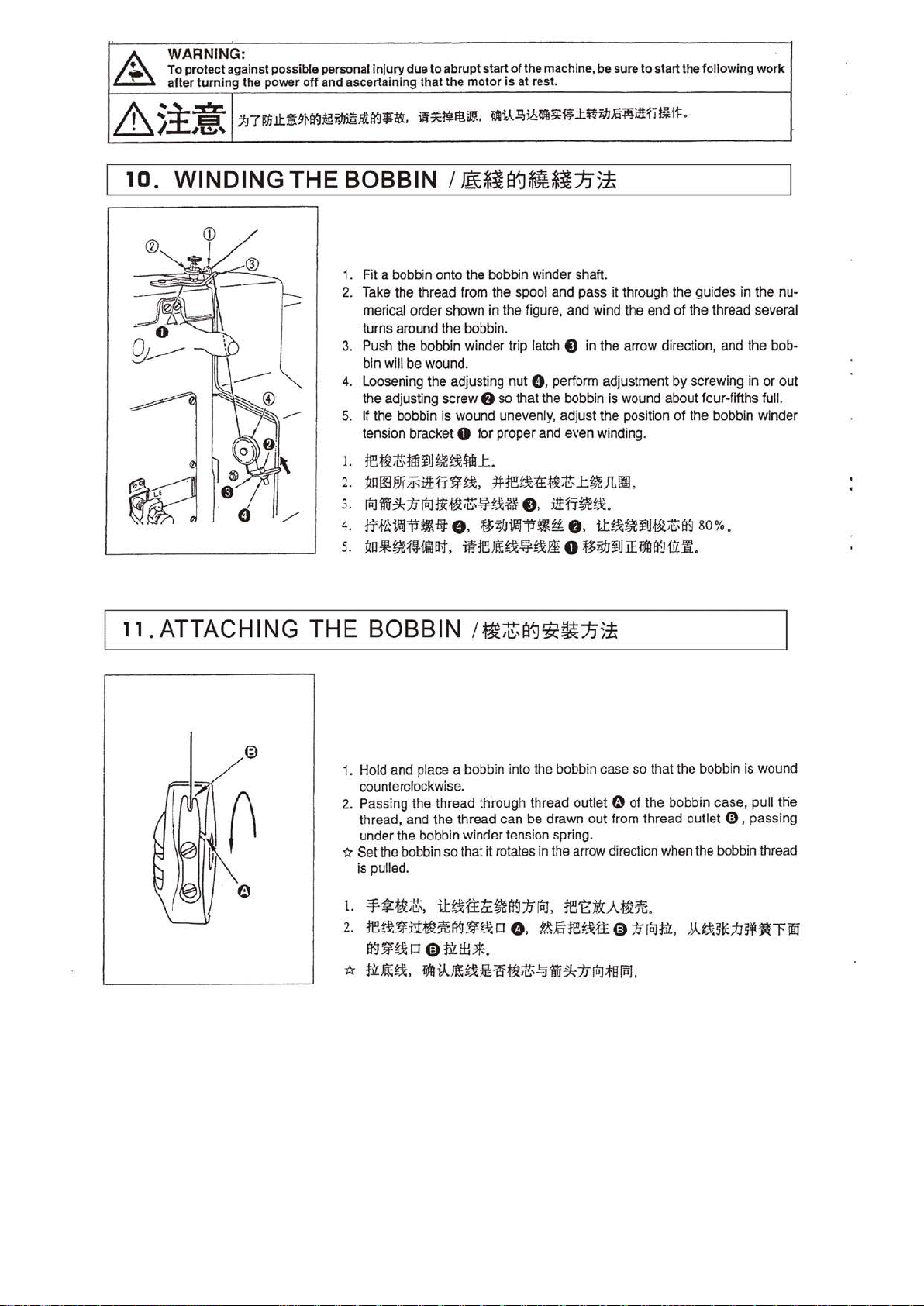
&.
WARNING:
To prot
ect
after
against possible personal injury due to abrupt start
turni
ng
the power
off
and ascertaining that the
motor
of
the machine, be sure
is
at
rest.
to
start the following
work
&
10.
~
:!:.xr.
/. ;f!f]
WINDING
:tJTilnll:~mt-J~M@J£1't-J1J1&,
..
THE
in~~lt!.i!J
BOBBIN I
1. Fit a bobbin onto the bobbin winder shaft.
2. Take the thread from the spool and pass it through the guides in the nu-
merical order shown in the figure. and wind the end
turns around the bobbin.
3. Push the bobbin winder trip latch
bin will be wound.
4. Loosening the adjusting nut 0. perform adjustment
the
ad
justing screw
5. If the bobbin
tension bracket
1.
ffit3l~1m:¥1HJWG4"1!1L
2.
:tm
oo
e;r
~:izHr
3.
fiilWti:!k:lifiil~~;c:;~gx$
4.
trf'.Hifij"~-HJ:
5.
~o*~1~HilBt,
.
WliA~~fJI~~.ii:*V?JJm:Mi1Hi-HH'F
.
~*i~~*I:IJ5!
of
the thread several
t)
in the arrow direction, and the bob-
by
screwing in
f)
so that the bobbin is wound about four-fifths ful
is
wound unevenly, adjust the position of the bobbin winder
0
fo
r proper and even winding.
.
~
~.
.#-ffigx;&:t3t;c:;
e.
0 ,
.f$;/JifoJ-:p~t-f:
ifffill~~~-'*
_t~JL
1!1
.
uHr~gx
.
f)
,
il:~~:¥1J~$~
0
.f$;1J:¥1JiEfifU~Ul.W
80%.
.
or
out
l.
11
. ATTACHING
THE
BOBBIN
1. Hold and place a bobbin into the bobbin case
counterclockwise.
2. Passing
thread, and the thread can be drawn out from thread outlet
under the bobbin winder tension spring.
~ Set the bobbin so that it rotates in the arrow direction when the bobbin thread
is pulled.
L
2.
*
the
-¥*~Z.
regx~i1>MZ7ta(J~~o
~~~o 0f.llt!H~.
f.i'l!l~.
fift!R!Li:~~;;a~;c:;.!:jfti:!k1ffiil1§~.
/~Z~~~:t.n~
so
that the bobbin
thread through thread outlet 0 of the bobbin case, pull
iJ:~tttL~~:lilal,
o.
fe't::ti!tA~31i
M.Fore~tt01ffiilf.i't:,
.
».~51t1J~~~oo
is
wound
€)
, passing
tlie
Page 26
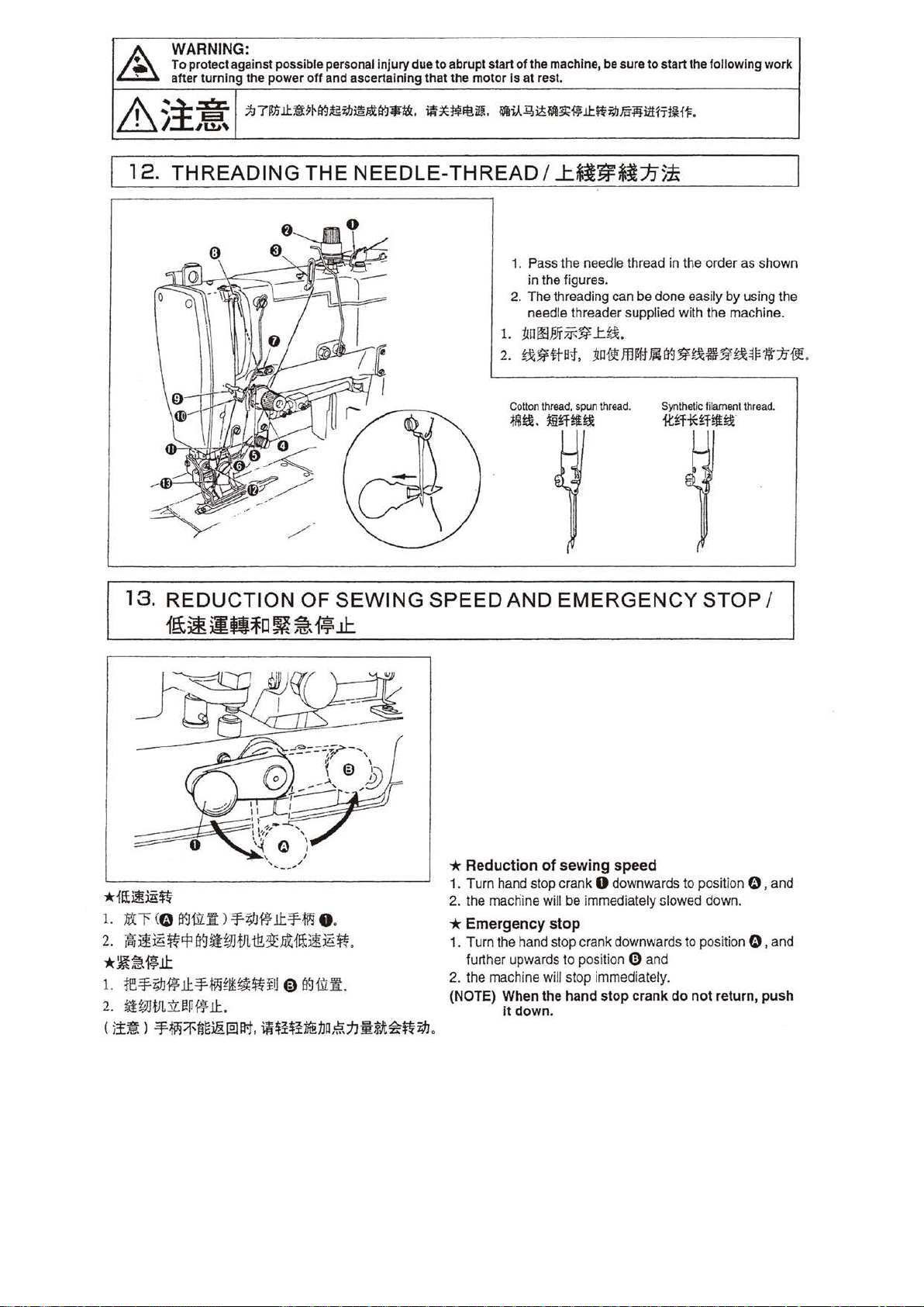
WARNING:
To
~
~~iXr.
12.
protect against possible personal
after
/,
turning th
,UJ,
e power
7:J
71ln
1.1:.
THREADING
injury
due
to
off
and ascertaining that the mot
~9~ti(J~TJJ~P.tti(J•ta.
THE
NEEDLE-
abrupt start
~*~lt!i!l.
THREAD
of
the machine, be sure
or
is
at rest.
~u~~~~~l.l:.ffTJJm~izH'Tt~H1:.
I
J::.$i~~JJ
1. Pass the needle thread in the ·order as shown
in the figures.
2. The threading can be done easily
needle threader supplied with the machine.
1.
:t!Offit'fff-$f
2.
~$f#B;f,
Cotton
thread,
spun thread.
~
~-~mitt!
to
start
the followi ng work
5
ti
by
using the
_ttt
~Oii!!Jf.lfflf14B{J~!:UJ~~~F'Iit1Jiit
Synthetic
filament
thread.
it~iHHi!!::lt
.
13.
REDUCTION
1t.t~
~Qlo
*
fi£~jgff
1.
:tit
"f <0
~ilL~)
2.
~
liliill
~
.:p
*Wt~~l.t
1.
re¥i9J~
2.
~Wtfl.:ll.~P
(
;!~ l :EF-~:if'liE~@la1.
11:
¥79J~.ll:¥-ti'3
~
~rtJJ.fJL
t!?/3l2
¥-mm~~iu
~
11:
.
OF
SEWING
~ ~
wll:
o .
~{~it
ill~
0
€)
!t:lU£:1
.
~~i~i~:IJ~.~:hm8.t~~~
SPEED
* Reduction
1.
2. the macnine will be immediately slowed down.
* Emergency
1. Turn the hand stop crank downwards to position 0 , and
2.
(NOTE) When the hand stop crank
.
AND
Turn hand stop crank 0 downwards to position 0 , and
further upwards to position
the machine will stop immediately.
it
EMERGENCY
of
sewing
stop
down.
speed
G)
and
do
not
STOP
return,
I
push
Page 27
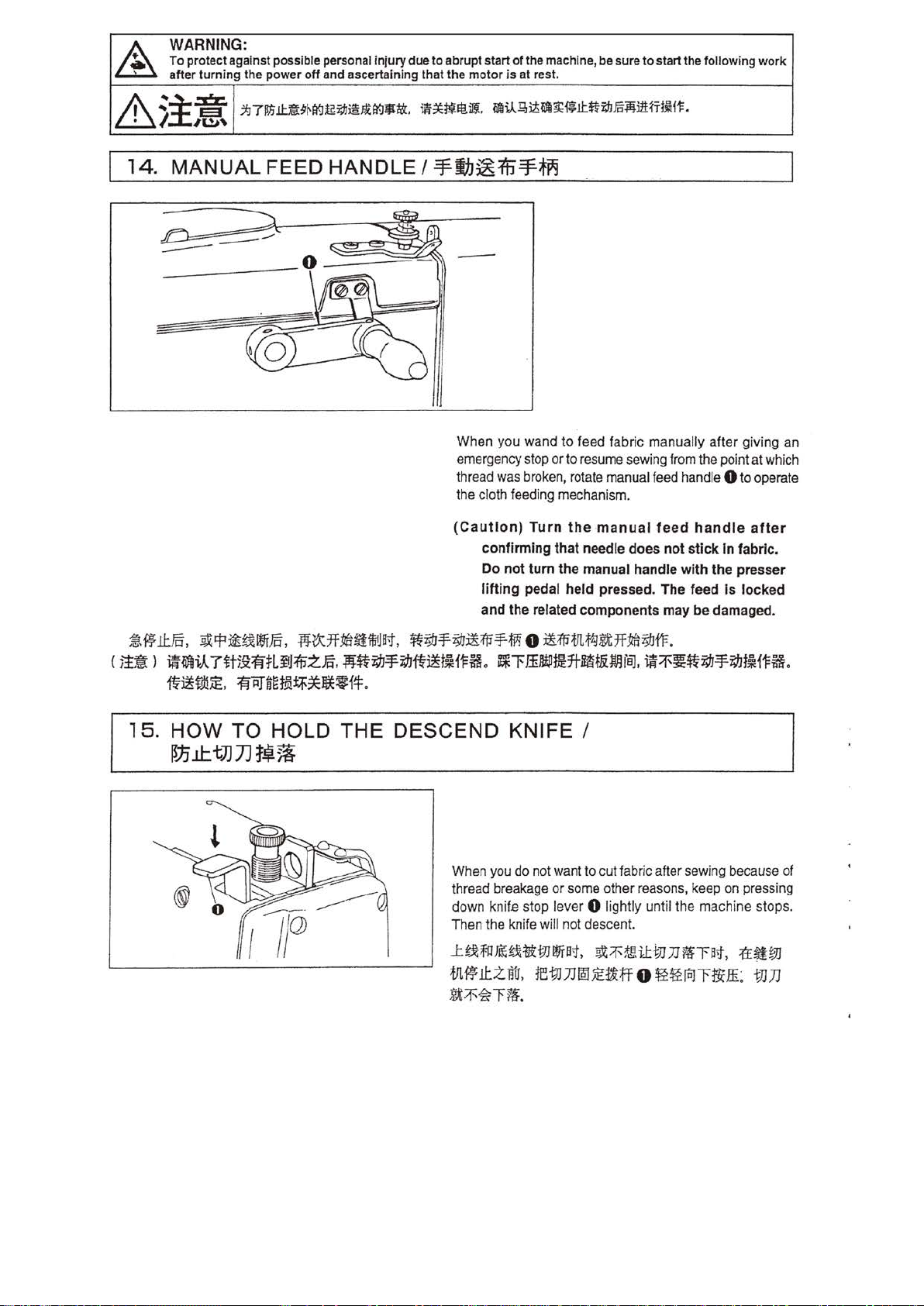
A
WARNING:
To
protect against possible personal injury
after
turning
the
power
off
and ascertai'nlng that the
due
to abrupt start
motor
of
the machine, be sure
is
at rest.
to
start the following
work
&
14.
:i.=:.
i
l&~
MANUAL
----
--
~7~.lt.:rmt~~rJJ@~!Y-11J1&.
FEED HANDLE I
i!*~lt!~.
M~iA~liiM~!kf*.!t.~rJJFR¥}:i1tJrl~i-t:.
=¥!h~15=¥~~
When you wand to feed fabric manually after giving an
emergency
thread
the
(Ca
stop
or
to
resume
was
broken, rotate
cloth feeding mechanism.
ution) Turn
confirming that needle does not stick In fabric.
Do
not
lifting pedal held pressed. The feed
and the related components
the ·manual
tum
the manual handle with the presser
sewing
manual
from
the point at
feed
handle 0 to operate
feed
handle
Is
may
be
damaged.
which
after
locked
~,
C
1!~
15.
~ Jl:J§,
l
~t:ft:Jt¥£Igfftf,
Jii{l)li.A.
7H)9:fl'~LfiJ1iJ~~
~~t.d!~.
fl''ii)"fi~t9!~~ll**f!f.
HOW TO HOLD
~J.j
J1:.
tJ]
JJ
1~
.fiJtXJf:llfl~itfJB;f,
.
.1ij:~~-'¥~~~tfH1=ft.
THE
~i#J-¥i#J~;(p-¥-Wi
0
~;fptJl.f1gglt7f~;I.JfF.
~l'Jintllt.JHt-~t&Wl
DESCEND KNIFE I
5I
When you
thread breakage or
down
Then the knife will not descent.
k
d~~-·~-~
m~ll:z~.
Ji.t~~Tii
do
not
knif.e
stop lever 0 lightly until the machine stops.
m~n~~~ffo~~~r*&
.
iBJ.
iii::f'~~~-=F~tfHI=ti.
want
to cut fabric after sewing
some
other
reasons,
keep
•~•fr~n•T~
because
on pressing
of
~•m
:
mn
Page 28

I
16.
TYPES
OF
STITCHES
I-~*~~
.<fl:tiit3J1JL
~0~~
1)
2)
1ir
2
fl
Mi~%~
.
mt9U1~
~~*WR~L~.
1ItmPtH.il
~~L~*h.
tll~
.
17.
.
1::1fl
~W~~
Ld·~
THREAD
0
:l!
1.
~
t!T
l!I!i;f!l2.
~~~t!T
~M
.
~~~
-~~~-~~~
TENSION/
This machine is capable
stitches, namely whip stitch 1 and purl stitch, 2.
1) Whip stitch
1i:
The whip stitch is formed in zigzag showing the needle
thread only on top of fabric, and the bobb'in thread on
the bottom.
2) Purl stitch
.
When applying higher tension to the needle thread
permit it to pass straight through fabric, the purl stitch is
formed
by
the bobbin thread which is pulled over from
both sides to the cente r line.
of
forming two different types
ti~*.1J
of
to
* Adjung the thread tension for purl stitch:
1. Adjust the bobbin thread tension
adjusting
2. Adjust tension cont roller
tension so that the
whip stitches. If the tension is too low, bar tacking seam may
form thread knots on the rear face of fabric.
3. Adjust tension controller No.
parallel side seams
*Adjusting
1. Adj
adjusting
2. Exchange the adjusting springs of tension contro
and No. 2 0 each other (the tension controller No. 2 will have
a weak spring).
3. Adjust tension controller No.
end of a seam.
4. The stitches of the parallel sides or bar-tack can be adjusted
by te nsion controller No. 1
screw 0 of
the bobbin case.
bar
-tack part
0 by judging from the stitch formation.
ust
the thread
the bobbin thread tension
screw 0 of
tension
the bobbin case.
No
to
approx." 0.15
. 1
f)
for proper need le thread
€)
is formed by well-shaped
2 0 for proper tension of the
.
fo~
Wh{p
to
approx.
2
f)
to prevent ravelling off at the
f)
.
to
~titch:
0.4
to
ll
ers No. 1
0.2N
by
0.5N by
f)
*
.lH#iDlHl!fl{]~j{UJ
1.
Jfl~'iG~Knt~~~
2N
;(:j
.
.
ti.ti.
1
~~·liEn
flt
(1(]
t~ ~IE
1
tX5lEJJf!
.
.
- 0.
2.
if.l~~
•~~a~. <~•woo~~~:±l~~.
~~ 1 t~~IEn~.
3.
::<t-T:if-1f~~
~8lJW11.
· *
+AH&:itl
1.
JfBIEn~~ 0 t~
ti
2.
£~~
ifaJTi~Wt
3.
Jfl ~ HB*
FciJI!Hx
4.
ffl~ 1 ~t51En@
!!!~
0
J~ffi:tH
~N e ~ili~:±llffi-
I:E
ni1Wi1
:Jta
~i1.!1-tYJ.tl~
)
A
(J(]~tBJB:f;A:,
il'f
Jfl~
2
n
JiHx51:Enf.JTi1'1
e
;fO
~
< m 2
gx5*JJff~H~~
iJ
li~
8
ilHi
ir.l
f)
iJtl:P:iJ!-qf~~.
0.4 - 0.
HxjJE
JJ
:m
-
"£.
Ti,
:if'
i.Ur!
tmt~HiUWJ
1'1
gx51Ch
ffi
iJ
0.15
~~
5N
8
!'f.J
>
iC
T
Page 29

WARNING:
~
To
after
protect against possible personal
turn
ing
the
power
off
and ascertaining
injury
due
that
to
abrupt start
the
motor
of
is
at rest.
the
machine,
be
sure
to
start the following work
&
~i:.:1%
"
~71lfi.l!:.tt9~(f]~~~nt(f]•tt.
,rm~
~
~~~t~.
i!.
~}J-ll,lt~~J;.I!:.~~m-Mu
*Adjusting
stitch)
The suitable range
*
f.iL~s~~
tef.iL~~~tif
ZffJB;Jt'f.J5!E.7J~1tJ.fif.l1)1iJ
~~m~••~ifh~M~~.
~tJ.H~JJ1
~l!tJLr.JB'~~5!iJ.tot,
te~i~
~~-;tJf.iLS
(
.m:<~mn~~)
0
B~tJ!~itf.ril"fit
iH
U~~il:frff
~f:
JJ1t.U
U
~5iEJJ
:ff
••
M~J.f~:k.
is from 6 to 8 mm with a starting tension
8 - lOmm,
0.1 - 0.2N.
•~*~~
0
~{JJ~!J.f:~i;IJ001J.
ll
t£~~t e ?r~tt~r.
0
tr.J
tJJt.iBl:~
~~-i;IJ~~.
a
;tJf.J1J
te~
te
.
For adjusting the stroke
f)
screw
9 to turn the tension post.
post
To
adjust the tension
thin 'screwdri
with screw
spring increases when the tension post is turned clockwise,
and decreases when turned counterclockwise.
, and insert a thin screwdriver into the slit
f)
H'f~f~.
the thread take-up
of
the stroke
of
the thread take-up spring, loose
of
the thread take-up spring, insert a
ver
into
the
slit
of
tightened. The tension of the thread take-up
spring
of
thread take-up spring 0
tension
of
0.1
post
9 to turn it,
(for
to
of
0.2N.
tension
purl
*Adjusting
*
1ftS:fi~if.l1'
••••~M•a~£mdsm~~~R•tr.J•s~
:$!!
.
a.
#!J!itlJJ*J.B;f,
~i;1J~d=H-.
tJtdii:~:k
b.
f.lf~J~t.tat.
fM~:i:~;J\,
fj'f'~~d:H-
.
te.f;!fXff o
0
tr.J~;Em~f:
~~~~1~tx=H-.
f)
,
~~
thread take-up lever
The th read take-up
should be adjusted
sewing products so
a.
For heavy-weight materials, lbosen setscrew
gui
de
0 , and move
thr
ead take-up amount
be increased.
b.
For lig
ht
right.
The thread take-up amount of the thread take-up lever will
be reduced.
the
thread
amount of
in
as
-weight materials, move thread guide 0 to the
take-up
accordance with the thickness of the
to obtain well-tightened stitches.
the
thread guide to the left. The
of
the thread take-up
amount
the thread
take-up
f)
in
lever
of
the
lever
thr~ad
will
Page 30

WARNING:
To
protect against possible personal
after
turni
ng
the
power
off
and ascertaining that the
18.
ADJUSTING
itUi
:ft
jjz
(~
1. Pull out cover 0 , and raise cover
2. Loosen nut
po
int 0 to a desired length on scale 0 (this length is the same
with the knife width), and then retighten nut
3.
Through
accurately to the extent tha t the bar tacking seams are not cut
by the knif
f)
by the spanner supplied with the machine. Set
your trial
e.
sewing,
1h
THE
;)
f)
adjust
injury
due to abrupt start
BUTTONHOLE
1¥-J
~
frJ
.
e.
the
overedgi
ng
length
motor
* Changing the work clamp check
Use work clamp check 0 having the size nearly the same as that
of a buttonhole length. .
se
By removing
together with a work clamp check holder as a set.
tscrew 8 , a work clamp checks can
be
changed
of
the machine, be sure
Is
at rest.
to
start the following work
LENGTH I
L
~til?'~~
2. ffllltl
?fE:JS;tprtMfli
ll:ffi
w
.:t:!tte~
3.
-~~-~-.
'li~
.
*ffMJI!r.J£~
m1tJ!Hl:iliJiltoDrH~I!HI~ffi!ll.jl
rl'.f'aff.B!IJ~J;E~~£
ji
raJ
O.
~i'iJ£Hil'~5'~~
B9
t&
~
rr
.f'HSt
1lt
8
J:~!l!~~tlft
B9
R -·n.
?&
-Bt
o
rrr*
m rr
-~~lltJJJJ
f)
,
~1lJI2H!~ffi.B!IJ.
f)
e. m m
C
l:jtJJ;:{jJ
1u~
-Bt
e.
.
.:t:
tJJ~~~
0
.
.
<t
t o M
JJ~
Work
clamp
check/Work clamp
check
holder set
£E!ll.jl~oJimm
81552-781-0AO
B 1
81552-783-0AO
552-78
Part
2-0AO
No.
#
89~%
6
.35-18.05
6.35-25.4
6.35-
Applicable
PJI;.(1tffl89tJJJJ~J.l
3 1.75
mm
mm
mm
knife
width
(1/4'
{ 1/4
(1/4'-1
-3/4')
'-1
')
1/4
')
Page 31

WARNING:
~
To protect against possible personal in
after
turning
the
power
off
and ascertaining th
jury
due
to
abrupt start
at
the
motor
of
the machine, be sure
is
at rest.
to
start the following work
&
:i:.:~Z
I
19.
REPLACING THE
ii)f
/!~JJ~.J!~mf
1.
tr
f'ki;JJJJ~J£
:f(~Bt, r
.
2
B':Jlfe~jg
(
i!~ l ~
-~~J:.
::.tJ71inlU!
lfil-.
tJJJJ
B
;f,
1'-f:£
f)
ll*iiJ~
JJ
:i:
mm
2 _ 3
' retightening the setscrew.
mJt
9
~((-J~~@~B':l$$:.
KNIFE
ifl
ttJm~
ur~1:W~B.J!i*
,
re~
JJ
0 ft]ffl:Jt-
1ff
#.:
,
i.t
tJJJJ:f0 1
fi'~~JJ~JE
.
ij{
H
/t
®ffllr.
NH~L.ITf
f)
.
i}V;,.;~ft!iw..
f1Ail-~~i139;~ll:.~~.lii~i1Hi'fi{~.
JJ~JJI¥)9!~
When
sha
rpening
follows:
1. Loosen setscrew
the washer.
2.
Attach the kni
.
end of the·slanted knife blade comes
above the surface
broug
ht
down to the lowest position . .
(NOTE)
Do.
not
or
replacing
f)
, and remove knife 0 together with
fe
to
the
of
the throat plate when the kni fe
forget
to
the
knife hold er
install
the
knife, remove
so
that
the higher
down
2 to 3 mm
washer
it
as
when
if
20.
ADJUSTING THE BUTTONHOLE WIDTH {STITCH WIDTH AND
TACKING
tiliP!t~lft
t
iW
* Jm
~
r
?N-®il!Hr
1.
f.lU9J~Jl
e
8':1
2.
JJo~fiffli!J.t
~a~tiHt 8 mlf-a~fi'll.!r,
3.
;{:i
0 .
t••~~JJ. ~~~m~••~MJJ~tn
i[
(
.tl!
ift
:
i
!H~
8
a':Jlli.fi:
WIDTH)
(
liiifJ~M~01JO~~.if:Mlft
AND
BUTTONHOLE
.
ft;JJ~H 0 1e!J~.ft
mm)
.
0 .
.f.t;tJ~z.f:
,
o
i11£7'1
ft~t~~~
8
MlfE~1lJl-lfi
remn
0
J
~UJIJJi!
I
U~
0 .
~/£3itlVJJJtJJ
~
~
<b1.<
H;f 5.
~·
J
£ ' since
.xtlfUtl}j(
2
ffr
.
REFERENCE
)
~~.&#.iftili¥/lf.flii~iJ!J!l
The needle swings from right to left with the right base line
established
Perform the adjustment as follows:
1.
To adjust
pointer
sewn
2.
For adjustment of
screw
scale plate pointer U , making
as large
3. Adjust the position
or
line of the knife. As
base line moves to the left.
4. Through your t
It
changed. However, t
the left
4. utfrutfif.
5.
as
the reference position.
sti1ch
width 0 , screw
f)
to a desired value on scale plate 0 . The actually
sti1ch
width
will
be the half of the set scale value (mm).
bar
0 , and set
as
the stitch width.
out screw 0
is
not necessary to adjust the position of left
/!' T
ti:JiHi (!)
ffl~~~~-. ffi~WJJW~~~M.
iJ:
1t
rial
it
remains unchanged
by
screwing in screw 0 if it is cut
~.t
B<Jflt:
~
~ilHr
0%1:
fol
ft.
f~
;/J.
tacking width
_p
ointe r 0
of
right base line $ .
so
that it
screw
sewing, further perform fine adjustment.
he
left base line should be moved to
.
rr
f'~
~
..tl&ff.Jl1itillil~.
:!
,
tz;J
~
POSITION
in
or out screw 0 , and set
€)
,
to
the
the
is
kept away from
0 is screwed in,
when
H 0 :ti t
J!
nP
screw
value indicated
bar
taking width twice
by
the
. stitch wi
by
iH.t
lnJ
9J%
Jl11'l
BAR
in
or
screwing in
the
cutting
the
right
ba.se
line (!)
dth
the knife.
&
ft
i9.J
.
~
tl!.
;
p~
WE~~
out
by
is
i9.J,
O
Page 32

WARNING:
~
To
after
protect
turning
against possible
the
pow
er
off
personal
anq
ascertaining
injury
due
to
that
abrupt
the
mot
start
or
is
of
the
at
rest.
machine,
be
sure
to
start
the
following
work
&
.:i.:E%.
/.
l&~
I
21.
CHANGING
gc¥5
Symbol
I
(,j)
K
CD
M
N
0
fP
54
62
66
70
74
79
83
1[:%
88
* Spur gears
1.
By selecting the spur gears, your can control the
number of
2.
Al
phabetical
123, 152,
ide
ntification.
3.
Use
al
phabetical marks
4. T
he
position
by the t
The
~ire
t
he
gears are included in the standard accessories. All other
[
gears are optional attachments.
stitches
etc.
a combination of gears which have the same
numeral
will
hen
combination
led alphabetical symbols
:t:l71!Elt#9i'rt:J~i;~Jm:~tr:.J-t&.
dJ
345
300
285
268
252
238
225
212
as
marks
are
engraved
represent the
shown
like
A,
both engraved on
.
on
THE
sc~
Symbol
lC~
A
8
c
0
®
®.
H
8,
C,
the
number
of spur
in
NUMBER
~
F
in the
table.
etc.,
and
each
gear
installed
of
gears
the above table show
-
~
93
100
105 180
110
115
123
130
numerals
spur
in
stitched
provided
.
;,:~~~;w..
OF
200
190
17
0
160
152
145
*
!I!~"W~
like
for
rear
that]
1.
2.
3.
4.
< o
gear
the
ie})..~ic!iil:lti$lt*fi;IJJi5-:iiji1Hi'"fllkif
STITCHES
1!~~~.
i&~.t~~Hr
a<J
'
!ti~
.
Jff9:f)C
::f:-BJ:~
Foffii~~a<J-t!r~.t~tlfj{J!i~;&5Fttatfj{J<ft~.
.lf!a<Jjgt~?!Hf1~~~'1.
I
£tt)(8~~~155!
PJ!;.{~j;J;&t:flf.Jf~09#!fi.
A,
B, c ...
a<J~::t~
[i5]
a<J-t!r~liH-J~JHt.
JtftP,)jl1Jjg!iJ~HT~~f4.
.
·
llHnl23,
1s6
)
* Attaching the
1.
Push
gear 0 into the shaft so that it
in
on
the p
2.
For
ins
talling gear 0
push gear 0 into the shaft
direction.
*
Adjusting
Loosen setscrews 0 , and adjust the
0 to set clearance 0
cam
Number of stitches Clearance 0
93 stitches
115 stitches
123 stitches
spur
gears
to
gear b
ushing
f)
l
ocated
on
the
pin
whi
the
low-speed cam position
as
shown below:
or
less
or
less
of
le
their shafts
is
securely fix
nearer to an
rear
gear
bushing
turning
position
10-
12
Smm
0
it
in
the arrow
of low-speed
mm
ed
by
operator.
0 ,
*
t&~rt-J:tl:~
1.
»-.
f'f:
it.A..DtnW;§-
-~-
t¥.J~n¥J:.
2.
JE.
i!l~
f)
loJ
0
a<J~ii!J:
*
11.tif
Cl
~f.!J:ff
~~~~~~0,
0
t¥.Jm~t.
tt~
93ttl,;.('f
,
re-&~ 0 fru~Wlltra<JJ!~-&$B
~ ~
::tf
inJ
~;/J,
.
rt-Jif.J
fl
mT•~~•o«~~~~8$B
11sinn
123ft
filH1!:
Fo
10-
ffii
a<J
J!
r
BJ~j
e
12mm
Smm
0
~
t!T~
~
Page 33

22. ADJUSTING
THE
PRESSER
BAR
PRESSURE
I
Jl!lfali~JI!
:tJIDI!I~
23.
WARNING:
To
protect against possible personal
after
turning
the
power
off
and
NEEDLE-TO-HOOK RELATION/
injury
ascertaining
due to abrupt
The presser bar goes up 12 mm when the pedal
stepped down.
To adjust the pressure applied by the presser
fabr
ic, turn
pressure is not enough to prevent fabric from puckering,
turn regulator
~
:f1i
~
~.ffi~(l{J.ffihffl.ffi~~~-*
Fo
,
~ffi~ffin~x.
the
start
motor
that
presser
0 clockwise.
ilJ
fa;
B1
(!{]
ffiJII;p
of
the machine, be sure
is
at rest.
spring regul
iiHt il:
:19
12mrn.
0
~~~~
to
start the
ator
0.
00~.
llim.
following
is
bar
When
~~
~~-*
work
fully
to
the
fJIJt~O~~&I¥1~*
* Set
the
1. Bring down the needle bar to the lowest point when the needle is coming down through the center of the needle
hole on the throat plate.
2. Loosen needle bar connection screw 0 and adjust the height of the needle bar.
(Setting
3. Insert the-part "1" of timing gauge
4. Retighten the needle bar connection screw 0
(Setting
5. Loosen setscrew 0
6. Rotate the driving pulley
7.
Insert the part "2" of.the timing gauge into the gap between the bottom end of the needle bar and the throat plate,
where the bottom end of the needle bar touches the top of the part
8. Align blade point 0 of the
approx.
the setscrew of the hook sleeve.
(NOTE): If stitches are skipped, lower the needle bar
*
flllHil:ME~
1.
2.
(
~:@tf*fr.,j/ft
3. fEiiiltt
4.
fi'~HH:f!:'lf@JJ;E~H:
(
~:i'EME~B9{lLE:
5.
JFJI!H~B<J#ft&~~~~
6.
7.
tt:!IE
8.
i
(
11~ l ~$:llMtat.
needle
the
the
0.5 mm (1/64") is provided between the needle and the blade po
feiHt~3iU.Ifi
tTtHtff~~@JXE~~
R.
fn
J
.iE
AA1.1J
J tt
R.
.t1ittf?i92
to
hook
rel
ation in
needle
bar)
hook)
of
the hook sleeve by the
in the
correct direction until the needle starts to go up from its lowest point.
sewing
.
i~~~l'?Jf~ag:tJ;~izH'Tif.J:P.
r
.~.
iHJl
Hfi
the
following
f)
into the gap between the bottom end of needle bar 0
to
bar
hook with the center of needle
way:
adjust the position
spanner supplied with the machine.
by
approx.
of
"2
" of the timing gauge.
f)
. and make adjustment so that a clearance of
0.5
iiiJH:lfifMHL'fl ~ ..
O.
.
)
8
ft-1
"1"
ft-Jfr~?t1i~A
it.f&
f)
~ttH 8 "'F~Zii3J,
#-i.tftHJOIJ~R..
0 .
.
l
21'ME1~rrtl1~~1fil;E~H:
lul
~Hi.J!.ll!
iJ!J
bt
#!'
lt,
8<J
"2"
0
x.tltE.fJlit"
ft-J~~?t!N
itfiJ:HHB9~Ji~tfol:!VR
~tll'l
f)
1¥Jifl,l.'.
#H
!£
jg
)}di
·
~:flllHFffJOZfa],
.M!f?i9C~f!LH.ZfHJO'-J
0 .
"'F.~
7f
.!!ill:.
ttHIOtllfil tt
.. , ..
{E£
o.smm
ft
l'f..P!k
~.
KB
I'8J~
!:h~'1
0.05mm,
:li::ti.
and
throat plate 0 .
the sewing hook.
in
t of the hook. Then, securely retighten
mm (1/64") from the timing
gauge
'f.
fE~'H!Hih1~3k~;;EUW:n
"1
".
'~.
Page 34

WARNING:
~
To protect against possible personal injury due
after
turning
the
power
to
off
and ascertaining that the motor
abrupt start
of
the machine, be sure
is
at rest.
to
start t
he
following work
&~~Xr.
/,
24.
ADJUSTING
j]TJrJilt
l&~
:@:
mt-J~i;IJ~IOCIY-J*$:,
THE
THREAD
~*f*ft!~. ~i.A.~ii;~~~ll:~i;IJFR~i1H'T
~~~~~~M8{]~~
*
gg
1
r&~*11Htt-:Jf.:}r&
~ 1 ~51E1Ji*
* m 2
~.!Bit7JHtt-:lfM&
m 2
r~KtJ?.n A tEJmi!Il!.i8'~fllfiiifi
fJ':f't~/l:J.~~
:f'UxHtWJ
B
&if:i.i!f'JJ
O
W:ti:1A*iftl
,
ff:r~'ii
'
~:tflaJftisi:J7f';
t
JL?t1%~
Ll:H>Jr-1-~.
1J
rtnfU1
J
·
fir¥,g:ffi:
,
7¥!8;fi!];]0
1
tHH]~
51Ef.Jfi#i&fll1-J
i'TIX3fM!t.itili~B<J~tt.t.
f)
:f
1l~ 2 ttt~CJ~
TENSION
*
Thread
Threa
d tension disk No. 1 0 rises only wh
mac
hine
Its standard
Adjust the rising amount by raisin
eig
ht of the thread tensi
h
*
Thread
Thread tension disk No. 2 0
bartacki
ng section
to
the
sewing start.
The
rising
0
an
d pulling our or putting
am
ount
is
at the sewing start should
tension
release
start.
(For 123 stitches.)
To
adjust
release
cams 8 and 0 to
the timing, and
.5-
lmm
,
RELEASE
tension
has
tension
amount
0.5
the
lmm.
3fMI!lttf<J:f't~MrDJtJM!tltiE2
0
release
entered the stop moti
rising
amount is 1 mm.
on disk
release
and
to 1
mm.
finishes
thread
move
ffl~ 1 r.BIE;/JtfB~..tr:ti:~jlllj&*ifWW
r
aJr¥.®
iYJfttJHitr,
of
several stitches from
can
be
adjusted by l
The period of
within 2 to 3 stit
tens
ion rel
the
them
to t
.
&li!1JffEl8
fi{f.
TIMING
of
the
thread
tension disk
on
state and stopped.
gnoweri
No.
1.
the
thread
tension disk No.2
is
kept risen between the
oosening
in
of 0 . The appropriate
thread
be
adjusted
ease
direction of arrow to advance
he reverse direction
so
ches
timing,
I
en
the sewing
ng
the attaching
the
sewing
tension rel
that the thre
from the
move
both tension
-
Ht
. 02Hlll1)
setscrew
to
.
No.
end
rising
ease
ad
sewing
retard.
1
.
Page 35

~WARNING:
To protect against possible personal
·after
turning
the
power
injury
off
and ascertaining that the
due
to
abrupt start
motor
of
the machine, be sure
is
at rest.
to
start the following
work
~:i:Xr.
I.
l~~
25.
ADJUSTMENT OF THE BOBBIN
;q7~.Jt1i~HI'~~iJJ~.fi.ttt-.llJ$:.
~;tt~Ft~~~
il~~lt!i!!.
~i.A.g,i.ZiWt~~.Jt~iJJ~M-liHl-1¥1~
PRESSER
UNIT
.
I
The bobbin presser unit is a unit to prevent the bobbin idling at the time of thread trimming
off of the thread at the sewing start.
Loosen adjusting nut
clockwise, the pressure will increase.
:titE~ffiJt
rrf'tf.l~~-llJ:
~ItO
0 , and turn adjusting screw 8 counterclockwise to reduce the spring pressure. If it is turned
11:
"W!XH-ttifE~~
o.
fli:lti~;~J~~~~
If
the bobbin thread is cut short, the pressure of the bobbin thread is too strong.
$U
il
:tf~~a-t~E#,
e.
~~
1¥1~~. ~~W1~l1~B-t,
sfti~£EJJ3t~~.
~f5!
jj~,c.'
&fli:l~lYJ£En3ts.M.
or
stitch skipping and slip-
ffiJt
I¥J
ffi
JJ:i1:k.
Page 36

WARNING:
To
protect against possible personal Injury due
turning
the
power
off
·after
and ascertaining
to
abrupt start
that
the
motor
of
the machine, be sure
Is at rest.
to
start the following work
26.
27.
ADJUSTING THE BOBBIN THREAD
~~m*i~
s:
8{]
ID!J~
ADJUSTING THE SPEED
WINDER
Loosen screw
between
becomes approx. 1
belt.
If, however, the belt touches the pulley, adjust the tension
of
tension pulley 0
And if the belt still touches the pulley, increase the clearance
to more than 1 mm .
•~•~~•~o*•"·
faJI!!R1J
MM,
~-~i51J~IJ\
~Lt.
f)
to make adjustment so that the clearance
bobbin
lmm.
~--·~*~"·
thread
mm
to
trt.H~~£
:floW:-rurM~MB1!Mre
TRANSMITTER
I
winder pulle
when pulley 0 is
decrease the deflection of
~•~o~~•z~~
e
-*izHrim!~.
-~~*~~
y 0
apart
-
r
amu~m1.J
I
and
belt
f)
from
the
the
belt.
~*~~
1mm
5~~
fl:B{j~~
*lt$7Hf1:li~
•~¥~W~¥M,
iJ:&:*In.lf~•~•~
*
t~
±~!J
~agfJ[,ii
••~•tt~"·
~il:&:11i
* Adjustment
When the hand stop crank is turned down to the low speed position, loosen screw 9 and allow the belt to move onto low-
speed pulley
*
Adjusting
Perform adjustment
of
the position of the belt shifter
0 , moving the position of belt shifter
the stopper screw
by
stopper screw 0
so
that belt shifter
f)
.
f)
»-?3J•~*~
does not cause the belt to come off high-speed pulley
•~R*•m•~.
o
f!;~.
~11Ht~~'m'tl!7tff
mm~•~o•~~••7tu
o
_tJDHftr*.
n~•ti
e
e.
e
0 during high speed operation.
Page 37

WARNING:
~
To protect against possible personal Injury due
after
turning
the
power
off
and ascertaini
ng
to
abrupt start
that
the
motor
of the
machine, be sure
is
at rest.
to
start the following
work
&
28.
~:£::1%.
I.
lcrl~
ADJUSTMENT
;tJ71lnlts9~~~~l§PX:rt-rJt&.
OF THE NEEDLE THREAD
_t~tJ]~B<J~~
~~~lf!iJJ.
"
i.A~iti"~w.It~~m;iilH7t.iHf
.
TRIMMER
I
* Attaching the
Loosen setsc
Set
the
it
does
the length
height
not
touch
of
rew
0 ,
of
trimme
work
remaining
. * Closing timing
Adjust
the
closing
tim
th
e trimmer completely cl
the
To perform
needle
thread
-the needle
the
closing
(
NOTE)
Confirm that an allowance of 0.3
left between the blades
trimmer has completely closed.
If there
i
trimmer
movement
adjustment, loosen
trimmer
thread
trimmer driving plate
timing
is
is
nt
erfere with the operation of the needle thread
* Opening timing
Adjust
the timing
begins
to
open
(3
/32"
to
1/8
To periorm
need
le
thread
moves
towards
(NOTE) : Take care not
trimmer driving plate A
of
gradually
")
from the
the adjustment, loosen screw 0 , and move
trimmer
you,
trimmer
and adjust
r 0
clamp
thread
of
the needle thread trimmer
ing
of
oses
driving plate
delayed with
no such allowance, the trimmer would
driving
of
lifting lever
of
the needle thread trimmer
the
thread trimmer
at a di
start.
driving
the
trimmer
to
cause the already fi xed needle thread
as
check
the
plate,
plate
the
height of trimmer 0 .
low
as
possible,
f)
,
in
order
on
the
need
le after
needle
thread
tri
when
it
advances
screw 0 ,
A 0
back
and
is
moved
reduced
stance
begins
0
amount
to
of
the trimmer when the
preventing smooth
f)
.
so
that
of
approx. 2.5
B 0
back
and
to
open
to
got
out
of
provided
to
minimize
trimming.
mmer
so
farthest.
and
forth.
towards
of
closing.
0.5
mm
the
trimmer
to 3 mm
forth.
earlier.
position.
that
that
move
When
you,
is
As
* t]J
]J
l'fl
g(
~
rrf'~~~f:
J:.
~x
m••~~m~.
ffj~-,¢.\
*
tJJ
JJ
i)]
JJ
{$
~~·He,
~~-ttfiU~ff~~~~~-~.
o.
r~~lli/1!1lf!f:ff/1!1l
llJ
~
!l!J
~.
&/l!ll••~~
.
~
m
!'fl
fEl
2V
11'1
fBJ
ilHiH~A;j'
I
iP.Hi'HJJ
ffi~YWJJ~~~A0~~
e fntnJJ e
~
rewnMffift~~
JJ
:ki~Hf.J
lliJ
~B·JIBJ
3!::J,".
(
;!.
)
t]JJJ~~Z.$, Jl~j}..j&J~Hf
~l'fl~~
~ti~~.
*
tJJ
]J
~
ff{W
it
~itli1fM1~1E1f
trf'HV;{H
rOJ
liHt
(i!•J~ml'fl..t~mn~~•A
.~fi
~~·~ll't.
ffiJI14ltfHHf
5* * l'fl
[Ej
2V
JJ
tHJJ
JJ
tE
.
e.
fllj~Ui;iJ..l:.~tJJJJ
~
5!HFH
11'1
fB]
J.A
ff
•J
liil
ti
0
Ml
nu
~m
titA9
.
2.
41J
0.3 -
WJJ~~WJJ~~
.
5 -
3m
m li:
~~
B0
o
-~~••M
/Ft~~1f.
.
-~*
~fi
~~~~
0.5mm
:ti
(f.)
.It 1f,
~~
31dfffiiJW11
.
;!i
.
Page 38

WARNING:
~
To protect again
a
ft
er
turning
st
possible personal In
the
power
off
jury
due
to
and ascertaining that the
abrupt start
motor
of
the machine, be su
is at rest.
re
to
start the following work
&:i.:a.
J,
l&~
29.
ADJUSTMENT
fit
*i
tJJ
;fJ71l!ill::.~~~£t-J~i;IJ@I££t-.J.ij:,
OF
THE
7J
81
ID.'ll
~
~~~~i!.J..
!i.lii..A~~!i.li~~J.t~i;IJ.ffl1!ii1Hi"tl\H~.
BOBBIN THREAD
TRIMMER
/
w n ::f
·11e
T,
m ~ ""F
(l{]JJ
7JJ
A,
uHr*Jll1
(
)!~
) A $(t-JJJVJ
1.
:£~121~JJ
- O.Smm.
2.
i!J""F
m;~w
3.
fW""FJ!;(p~
4.
rtFc""F""F
s.
•~.
0
B;f,
n~~ff$!1J
B,
rrt~
m:~w~!IH-Wi~zt
•~tt-t&.rM•""F•awn.
When the sharpness
counter knife
counter knife with the oilstone
(Caut
ion) Never
1. To replace counter knife 0 . tilt the sewing machine,
remove
setscr
a clearance
blade point and the needle hole in the throat plate.
2. To replace bobbin thread trimming knife
bobbin thread trimmer connecting rod shaft
3. Remove work clamp carrier·
pes.)
4. Then, remove setscrew 0 of bobbin thread trimmer arm,
121
~JJ
o.
J~Hllll'H5?Vf
m
121
;.:En
.
-
~.i!'ll~~f~.
~fflJ!lfWVL~.
e.
J!~JiHxtJJ
41-<tt.t&.rM121~Ut~£.
0 .
i!J""FtitE~!el;.'EU{~£
n e.
ft1rrtt-t&.rM
ifl""F
m:~m~!IHm
mfi£~
and
5.
Finally remove the bobbin thread trimming knife from
the throat plate base, and replace it. When removing
it such a
knife 0
f)
.
c.
e.
of
the trimmer has got dull, r
0.
and resharpen the blade point 0 of the
or
th e like.
buff
section
the bobbin case positioning plate, and
ew
f).
To attach the counter knife, adjust so that
of
0.3 to 0.5 mm is provided between the
of throat plate base, and remove
remove
bobbin thread trimmer arm 0 .
way
as
twisting, bobbin thread trimming
may
be damaged from the pin section.
~~ISJ~JJB;f,
0.
CD
. loosen the setscrew (4
th
1EJJ3JfU#fL(l{J
emove
remove
f)
,
remove
first
0.
roat plat base 0 .
.JBJlle~§t1g
0.3
Page 39

WARNING:
~
&~i:~
To protect against possible personal Injury due
after turning the
.71
l
l~
30.
ADJUSTMENT
AND
J::.
*i tJ] *l tb
7it?ll:·?~~~fJJ~/OC~-;t&.
..
LIMITING
power
off and ascertaining t
OF NEEDLE THREAD
PLATE I
fF
81J
~
~Q ~~
161J
~&
to
abrupt start
hat
the
i1i~t~~iw..
8{]
ID!J
of
motor
the machine, be sure
is
at rest.
liiT!i.A.!!,i6liiTI~~J.tttfJJ~.fl}i1H"Tt,ijff
~
to
TRIMMER
start the following
.
HOLDER
wor
k
31.
TIMING
tJJ
JJ
51
JJ
FOR
~M
Loosen setscrew 8 , and insta
0
so
that it comes in contact with the blocking arm
the time of slow start of
engaged with latch A.
Needle thread trimmer hol
such manner that
64") when the needle thread trimmer opens.
fitWJ.tfL{~~.i§ijfJB;f
5:Ei~~£
e ,
.trxtJJ
JJ
~iofD>t,
G
1!3(:~
O.Smm.
DROPPING THE KNIFE I
8{]
~~
Loosen screws 0 , and move knife tripping segment
in
the direction shown
drop earlier. Adjust it so that the knife drops two to three
stitches before the machine stops.
ll
and adjust limiting plate
f)
at
the
machine (when latch B 0 is
f)
).
der
0 should be installed in
it
engages with cam G by 0.5·mm
(it.] BO
U:l!&ftiiJ:t&!Yi¥UII.Ilt~an*ill
il:.t
~
by
tJJ
the
~Q¥;)
A
f)
1!3(:15-B;f
e •
~
7#11t
an
lm
arrow, and
0
the
;w
(1/
),
:t'r.f't&ll
i>fltt:
8 ~
f)
knife will
rr
.f't
&ll5:E
~'-
H 0 ,
tJJJJf!
JJDtMt!!
~HJJtll.~.ltA<J
ioJ
lN
~
1f
iitr
,
&jj!iJtltjg,
2-
HtiW, iltJJJJff;JJ.
ioJ
~
191
tJJ
JJ
7#1
tF
lJ
~
f)
,
Page 40

32.
TROUBLE, CAUSE, AND REMEDY
Trouble
1 . Needle thread is
broken.
2. Thread slips
out of the
needle.
3. Wobbling
stitches are
formed in
overedging
seams.
th
e
Cause
(1) The tensi
No.2
(2)
The
take-up spri
(3} Blade point of sewing hook has
burr
(4)
Poor liming of the sewing hook.
(5) The thread path has scratches.
(6) The needle is too thin.
1) The needle thread trimmer opens
too early.
(2)
The needle thread trimmer opens
when
coming down.
The
. (3)
I the start of sewing.
1 (4) Wrong threading.
(1)
The tension disc
(2)
The tension and stroke of
take-up spring is not enough .
. (3) Bobbin thread tension is too high. o Decrease the bobbin thread tension (0.15 to 1 7
on
of
the
tension controller
is too tight.
tension
or scratches.
whip stitch is not formed at
or
the stroke of the
ng
is too great.
the
work clamp check is
No.2
is too loose. o Increase the tension of the tension disc No.
the
o Decrease the tension of the tension controller
No.2.
o Decrease the tension or the stroke of the take-
up spring.
o Buff the blade point of the sewing hook,
replace the sewing hook.
o Readjust the sewing hook's timi
gauge.
. o Buff the thread path by cloth files, etc.
o Replace by a thick needle.
o Move back the needle thread
B.
plate
o Move back the needle thread trimmer driving
plate
B.
o Decrease the tension of the tension controller
No.1.
o Perform correct threading.
o Readjust the take-up spring. 1 8
0.2N for purl stiches}.
Remedy
ng
by the timing
tr
immer driving
or
2.
Page
1 7
1 7
1 5
1 7
18
23
2 3
1 3
2 7
2 7
4. Wobbling
stitches are
formed at the
of
bar
sewing.
tacking
start
5. The needle
thread at the
first
comes out and
lumps on the
bottom of cloth.
6. Stitches float
over cloth.
7. Stitches are
skipped.
The
(1)
(2)
(3) T
(1) The tension disc
(2) The bobbin thread tension is too
(1)
{2)
(1)
(2)
tension disc No. 1 is too i o Increase the tension of the tension disk No.1 1 7
loose. [ (0.15 to 0.3N).
The posiiion of the needle thread i o Lower the trimmer as low as possible, provided 2 7
trimmer is too high.
he
stroke of the take-up spring , o Decrease the stroke
is too great. and increase the spring pressure.
No. 1 is
too loose.
high. 0.2N for purl stiches).
Bobbin thread
enough.
Bobbin
thread path on the bobbin case.
The work clamp check
for the buttonhole.
The cloth is made of light-weight
materials.
thread slips
tension
out
is
too large
I it does not come
I
o Increase the tension of
o Decrease the bobbin thread tension (0.15
is not
of
o Increase the bobbin thread tension.
o Properly thread the bobCin case.
the
o Change the work clamp check with a smaller
o Delay the timing of the needle and the sewi
check.
one.
hook. (Lower the needle
mm (1/2"))
in
contact with the work clamp
of
the take-up spring, 1 8
th
e tension disc No. 1.
bar
by approx. 0.5
ng
to
1 7
1 7
1 7
1 4
1 9
2 3
Page 41

33. STITCHING TROUBLES CAUSED BY OTHER REASONS
Trouble
1.
Starting
does
(The
clamp
not
fully.)
2.
Machine does
not reach
high
even when the
pedal
down
3. A loud noise is
produced with a
stop-motion,
sewing
does not lower 10
at
sewi
4. Stop-motion
not smooth.
The
5.
does not lubr
cate.
Kni
6.
during
speed rotation.
7. Knife is dropped
even
needle
is broken.
8. Needle is broken.
pedal (1) Needle plate, needle plate base
not
work
work
arm
lifted
up
the
speed
is
stepped
fully.
speed
the
end
of
ng.
machine
fe is dropped
high
if
the
thread
is
or
is
i-
or
clogged with fibrous dust.
(2) The needle thread trimmer
terfered by the work clamp check
or the trimmer driving plate.
(3) Pin
l
er
No. 1 is off from the tension
release lever.
(1) The h
correct position.
(2)
The belt
transmitter has not changed to
the high speed pull
(1) Im
proper setting
am
c
es.
(2) The flat belt is too loose.
(3
) The low speed V belt is too loose.
(1)
Stop-motion lever needs lubrica- o Lubricate the stop-motion lever.
lion.
The belt
(2)
transmitter h
the low speed pulley.
(
1) Oil level in the oil reservoir is too o Fill the lubricating oil up to "HIGH" mark. 12
ow.
l
(2) Oil is not circulated.
(1) Position of the knife trippi
ment is not correct
(2
) The setting
numbers
for
correct.
(1) The machine is threaded incor- o Correct the threading.
rectl
y.
(
1)
The needle is bent.
2)
The needle and the hook blade
(
touch with each other.
(3) Needle thread trimmer hits the o Readjust the· position of the trimmer.
needle when opening its blades.
Cause
bobb
in
thread
of
the thread tension control-
and
stop crank is not
shifter
for small numbers of stitch-
shifter
of
trimmer
is
in the o Correct the position
of
the
speed
ey.
of
the low speed o Readjust the setting of the low speed cam. 22
of
the
speed
as
not changed to
ng
seg- o Adjust the position
the low speed cam
of sti
tches
is n
Remedy
o Tilt
the
machi
ne
head
and
clean
them
is
in-
o Readjust the insta
position of the trimmer
Loosen the thread tension post nut and re-
0
adjust.
o Lubricate the shifter driving pin.
o Increase the belt tension by the tension pulley.
o Increase the tension
tor.
o Readjust the position
o Apply oil to the oil return felts. 12
the knife is dropped down
o
Co
rrect the setting
ot
0
Rep
lace the needle.
o Readjust the positions
sewing hook.
o Adjust
so
that the limiting plate
arm
touch each other at the time of starti
ll
ation
of
the trimmer,
dr
iving plate.
of
the hand stop crank. 15
of
the V belt by the mo-
of
the belt shifter.
of
the driving cam so th
at
a delayed timing
of
the low speed cam.
of
.the needle
and
and
the blocking
ng.
or
up.
the
at
the
Page
27
10
4
12
26
29
22
15
13
23
27
27
9. Feed is locked.
(1) Manua l handle
with presser lifting pedal kept de- the presser lifting lever and release the lock.
pressed.
is
being turned o Do not depress the presser lifting pedal. Lift
Page 42

~ff{
1..1.~~~
CD~ 2 ~{5lEiJ~.t
cv
miJB~~(li.J5!11JJt,
a>
ME
¥19<:
®
ME~:-f~$-
®~iili~fJH~
®tJl.H:i::tWJ.
2 .
..tfill!Hj;
3.
~1-T
'l:i~!li
~
m1¥
4. Mi!It!It
~:if'~
*
5. ~ 1
6.
1.
:IJ
O
1m
!:if
..t~b\:tiifl'ilr
OO!fHx
g)!i2}!1ft~
a:u~
CD
.1.
fi
iJJ
®
i&"F
lli
Q)
3f
Mi
~a-t
®
..tfifl'iJJ¥~1J~:-f)(f
;;f
CD~ 2 r.£51EJJ~:i1~~
cv
jj~rx54litu5!11,
a>
Jtf;~5IiiiJil5!iL
CD~ 1 ~sttiJWil~~
®
..t~tJJ~{.iiJI:i::t~
a>
jjH.£5tti.ffizront~u::k
/f'
CD~ 1 ~~51E.1Jmii1:~~
®
I!Hx51EJJi1:~:R
CD
JfH~51EiJtt~~
®
JfHJGb\
CD
lliJit.ll:k
®
;(p.f4AJ
Jjf,lt]
:
B!I1
.
~
.:§J¥1]
Ii!tfi
.
.
~JHT
7f:i::1:
Jit.ll,
J: ~i)J
:iF
1m
1i:
.
,
.f3l
5'\:Jm
ili.
ffi
tiJ
tL
.
.f$zro:lll.::i::t::k
1jj
1ilL
lf!.
JJ{~tr3f
1m
NlHii
.
.
m
zrom:re~
.
.
.
;J\
.
. 0
.
. 0 ~~~ 1
;J\
.
.
1
I
i
i o
I
I
I o
. o
~H£:11~
o~H~~ 2 51EiJ~~5!CiJ
~~~~!~5~~£l'.J5~.1J.
O!W3fhfE~9<:,
O)tJ~$-R,
o fflltV
fli
o£~!iXmn
o
tt
Fa
ft
o
11:
Fa
f$
O.iHfUt!!.~~
0
~5!11~
o
!:m~fiJJ
o~~liHxsttiJ
o~s!I1~ 1 tBIEJJ~
0
~fff[ll:j
o~,J,tM~5,~fl'ilmzromm~
o
~~!~ 1 rxs~EJJ~
o~~fff:~5
to5!11
J
iH.td*iJ
.iErou.ttl!!iH~
0
~!lX+ffilJ!ll
1ft
JJS
tJl
(
fe:ftfH'~r~
P,t!!
~~ttE~fl~~~
iiHVJ
EfJi-¥
.
zro
..t
ri
iJJ
i9J
.1.
~HJJ
~51EiJ~frtl5lEJJ
.
2
~51EJJ~
t
t~5tti•
.
fft
(g
7!'
!
UJ
.
.
.
.
tt
-fr
ME
-Ml
0.5mm
.
.f&~;J\fJ:zroit
~ME
13(
.
.
.
.
ri
zrofF
f&
s.
~
zrofF
t&
B.
.
.
.
(~i!Jit1~0.15-
.
(0.15 - 0.
~Htt
!!J
EE
Jlt.ll
,
~::k5,~ffin
.
(0.15 - 0.2N)
B~ ~ ~
Bt
fBJ
0.2N)
3N)
.
.
titi)
.
]il
17
18
23
23
-
13
27
27
17
15
17
18
17
17
27
18
17
17
17
14
19
23
Page 43

l!ll
1.
~
iYJ
~
(ffi~
lfrff&fl'
iS.@)
iiJ
-t&
;{\
i9J
l:itl. )
fF
.
J)
(?;
tt~,
H~li,
fl~~
.
1
~
w
JJ
!=:iII~
t&
~itt
.
~~
JtH.~W~~Ut~
li
..
tu~
tJJ
JJ
i#
o
nt
1
tt:
oti~~iJJJJ,
iYJit:
fl11
m
!Jdtt
i
(j<J
~HI:1I#r
rr
m
t3
.
~~i~ll~iJJJJ
& ! .
m
27
~ ~-
~~tcJJ~b\tt~!;fFff
fiT . I.
2.
~
iYJ;~~~J
1!!.
;{\~if
(
illlffl!b~)
3.5t~ifi17c
littl~*/6;{\~
l .
(jMJtl~i6)
4.
Jt~;J'It
s.
t~M
.
6.
r.i
l
BfW
r .
jg
JJ
i
~
.
~
If\
fi
cc
fiYJ~
.ll:f
.
X
~ l
ti
a3
~l&:fl£1l!t
(i:
·
t£ftJi:PH1a31l£lt!*H[i
(t
f&:1tri:J:m
@
fi
H~
v
*&:1irtttt
·
:D
)t~~~&fflltJ
ct
at
I H
(f)&:*
~lfi1ifl£~
J)
fJl~
id!f!~
(t
fJl7Itllf\
WI~
~
VJJJ#Jft:8~mit-f'xt
x
ttflj'BtB9f~tl~~m1ff.iE1ifil
11
.
fi'i(fl:JnliJ~r
&:
{fHtHt
~
;J'
.
1m~
f;IJ~J
.
.
.
on*•-~*JJffl!,
otef;tJ~
0
tt
ti
Jr
0~1118~&1,111~~~*
JfBt1J
o
ort;tJ~~&:#He89f.V:t,
lHIH~1Jo
*·
T
.
WJH~
;J'
f1M$
~
1
J.
(f)jdJ;J'JE
mt
.
i#
J. o
ott7t~~~
o~jflijl&:m:!t!fri(J%iJ1.
!~
otei1!11Jnl
f±
I
It
~ii
oiful!W
. o ~~ll8~udt
JJ
ll!fi~
.ll:fm~~J1itr1f
00:
;1J
flj
1
1J!Jid!
~!BKJJ
~
hoid!
.
.
.
.
5~~
v
%&:
·
26
HIGH
f;Fl[
,
i#J.@:it~
1
1JD7d!
.
m
JJntrnJ.
(
!~)
(
~.!fl)
12
29
22
10
15
22
10
4
12
12
7.1~lm~tJJJJfg
X
tflrxf~~~1ft*/f\xt
0 i
fJi
r .
8.
ltJj
tt
.
9.
f
H~WiiE
.
X
flltt~T
~
tJl
~
l:~tJJtH11*ffH
Q)
t£
t~r~t~#JTf#Jf*ft:ft
.
tUil~~ffHjl
I r
ffJ.~
.
i
m
fHUJi
f_
!=:iffltH1Hl
A9
:!*
~
OJ!itJtft
o
~~fll
Oiftj~iJJJJ&l"t
Oft~ittl~~~!~Mti~ijll
r,
olf\Jrffi~lffli
1*fFH
.iE
lift!
ft!n¥
f.t
.
t:UU!rH~B%1!
.
,
MF~W!iE
.
.
ffliffi•l*
.
.
15
13
23
27
27
Page 44

1.FRAME &
1 5
1 6
MISCELLANEOUS
COVER
COMPONENTS(1)
7
10
--GJ
1 1
1 2
1 3
28
29
~
68
69
71
~--t~
~
7 0
c
"<fr~
c:
y
78
~:
66
67
74
i
75
Page 45

No
Note
Parts
No.
!f¢;;.-t
D E S C R l P T l 0 N
.t
•4
..
,
___
Oty
Y.
I 1
+···
1--L-.!
1
,
2
_
.L
1
'-
.•
-.!
__
J_
1
2_
!
·.
...
--
-~~-
_
..
_ 1_
.!
'
1
2
'-·
6
1
J_
I
I
L
I
L
78
--
-·-
-, I
I 1
2
.L
1
1
Page 46

2.
FRAME & MISCELLANEOUS
COVER
COMPONENTS
(2)
---
~i
El
~~*1J~H&*a~~
r-----
L - - - - - - -
-
---------
~
- - ,
13
Page 47

-~~
MAtN
-
SH
------·-
AF;
-----
~
CQft.op
IV/
-------___
ON~N
1
.:,
iS---~
----·--
6
•
.,
'f'l11~t/4
~-------------------~----
1514
,-
l'
--
7
•
j,
~
- 0
- -
----------
0
2!
i
~
27
29
3
if~
4 s I
0-
I (]o -· 0
1 4 1 7 r - - - - ' 2 4 2 sf I
i \ \ /
,
~.4>'~
,J-
-! ,' G - -/
12
(
:· -::
--®-
~------
1
9. 2
0
,',_
·
j I I
21
16
-
---
1 8
~
~~~
-{)
30
DO
-
C:=J
__
,
I
_j
__
9
_
_j
Page 48

;00
. 2
3
;_J__ :00
s
. 8 •0
,
.J
10
11
12
13
14
15
16
17
18
19 003-0
20
·-·
21 003-0
22
23
~
...
25
'
26
21
28
29
30
31
32
33
--
3
~
35
,,
--
. .
36
.
37
38
. 39
44
45
46
..
-~-~----·--
48
49
50
51
52
53
54
55
56
57
58
59
60
61
62
63
•
-
~
_
65
67
-~2
68
3-000002
--:oo3-0oooo3-3-0000
-·
oo3-ooooos
:00
3-0000
00
3-00000
03-0
003-0
#01
00
3-0000
0 0
3-00
00
3-0000
003-0
#02
003-0
003-0
003-0
003-0
...
..;003-0000
.....
00
3-000020
GO
J-000022
.• 003-000023
00
3-000024
oo3-000025
00
3-000026
00
3-000027
00
3-000028
00
3-000029
003-0
003-00003
... 003-000032
003-0
00
3-000034
003-000035
____ 003-000036
.003-0
__
\00
3-000038
...
:003-0
. 00
3-000040
00
3-0000
003-0
G03-000043
00
3-000044__
00
3-0000
00
3-0000
.... 003-000047_____
• 003-000048
003-0000
003-
000050 ..
003-0
_003-000052
003-
000053
__;.
003·0
00
3-000055
00
3-000056
#02
003-00005
:003-000058
003-0
00
3-000060.,_
G03-000061__
oo3-0
oo3-0
...
003-000064
· 003-0
·G03-0
• 00
3-000067..
;003-0
01
04
--
06 O
7
00008
000
09
10
0 0 11 T
12
00013
000
14
000
15
000
16
000
f 7
18 ; CO
000
19 ;
0002
1
__
__
___
....
00030
1 , .......
00033
. ........
00037
00039
41
000
42
45......
46
49 S
·----·
00051
..
0005
4_
_ _
7
00059
00062
__
00063
00065
00066
00068
..
_:.
..
....
.....
•.
....
......
. . .
... SCREW 1/4-40
--·
·•--
.
......
...
..
·~-
.
...
_
~---·
. srqP
OIL
WlCK
HOLDER
s
oR~IJ
L~:
40
L~4
i
·
=-=--
IL WlCK
SNAP
RlNG
vtNYl.
_!ieE
_ • _
MAIN SHA
FT ___ --·-
DIRE
.
C].ON~
Ba
THflEA.D
.
!~~
LE¥ERASM.
HRfA
_!l
.!..
.41<!~ ~
!Yf:
NEEili.E
B~_R_~--
NEEili.EB
~.q
~.9QN~~QJ!tlG
.
E~!Jg
BEA~G
LEFT
SC
RE'!V
.......
o
;~~TWA§HER
•.
tl~
lli.E
ROO
CRANK
UNTERWEI
GHT
ASM.
SCREW 9/32-28
A9.
REW1f4·4DL
~
'--~~
SH!Ng F
~G~J
OJl.
FaT
OJL
~~
Kt.U=
K
~~~~~9
•
on.
~EA~------
-~s
§C!,ley/
WORMASM
scREW 1/4-40L:6
.... JHRU
.
SCREW
MAIN
SCREW 114-4
..
~PP
!fl.~~-~~-~~
UPPERSHAFTR~ARMETAL , ~-
_
Oih.SEAL
B~R\!1~
§.Q!l.;.'ll'
FELT 8 I
L
q9~!.\!\M!.
RETAINING RIN
FELT-6.GUfQL ... _ --. ...
BEAR!NG0
.
sc.~~-15/
CREW
~N
gAS
KET
T
HRUST
BEARIN
~C_REW
S:c.~W..t
DRMNGPULLEY
~gREW(C)
ST~9AM
STOP-MOTION
··
aAI(
E
S
!.Q
P:!t!
.)
TOP
SCRE!i.J.!!
O
IL
WICK
O
ILWIC
WASHERS
MAINSHAFTTH~STWASHER
L=1
6 Qif
:S
9/32-28
L716.5
!lQ~
T__....
_l_
~/64-28
L
=8
c~
-
--··
E
B~_ORI_Y!Ng
~~~~EQ
ST
SHAFT
SHAFT
.!fl}
_
.Q!J~
L=8
_15/64:2~ l
~
CQ~~.A
SM.
1/4~_
).:
_4.
THRUST
0 l=4.5
...
......... . ...
.
~
_1 1/64·4
~l=_~
._ -·~
G
30
=30
XSS
&4-28
L:a
9/
64-4
0 L= 3.5 . ll U
-
~~S.
!
WASH~~~--
G
1i
4-4
0 L
=S
.O
/
4-40L=~
PRESSURE
CAM
P!N
.SE~E.~--
Q~.JO§.!ll..~P_!
Mon~ q~
M.9nOtl.,~
.tR.f§.SE
~..:CJ
J::?
K.
____________
..
---·-
, ............ ~ .
R
ASM.
"
..
" I
R9 D
WASHER
..
. ... i
--·-·-·
...
. [.
EQTING
-··"--
-
!AT.L
.
.. --..
..
D=14.72W=12
5
- I JjiJ
COLLAR
ASM.
_ i !
~
ASM.
..
~
-
. I
..
~_EgL
• i
SP
!IJN
G -
SLIDE
BLOCK
N
_
!l..~
.
IE
.,
_
(C)
..
..
.
..
................
.•
. •
"'---~
...... ~ ·-
··-·--........
..
..
·----
..
·-·-.. _ ...
_
..
_ ...........
_
·------
-·-...
......
_,__ _ • !
-..
......
•
................
..
..........
-·-·--
. _" . ___ L
-~
-m.o
M
.-
..
•~•••'
_
-··
..
_.
~-
...
,
___
,_
-~·-
....
•.
....
____
-·-
~
,___ :
···~~.
1ur
il!JitJ!JJl.
L
~ ~
-
.1fli!
..
.1~U.i
.
____
.....
,tHitHL..
..
---··-··
..
I!Siff
Jtffii!!IR.
..
..
itffllll!fi~
1
:
i
I
l
---
-·!
..
i JliT
-
+!tiT
...............
lil
;amm
#.
~~IT.
.......
.. .
il!Jf!mm!
... .
itH'II!!iR~IL
lfttJfi
t'liT
~fill
~{!
·-~-----
it!i;;!;
---i ..
Jlli
llJ:hit
litf
~
..L
MJh
:tJ
!fi~fa
. j
...
~iT
..
f
...
il!l~li
·:-!ll•~±
!
~l
I !liT
...
!
.~lf
-·
------
------··'·
r.ur . __
! .d:U
ti
ll!
. ,; _
..
·,
1
tlif _ ..
~Ut
---~
---
·
ili!;tlli
!
~
, L
¢ii!il!l
(
..!tiT
.ii~
•.
•.
~.i
Ul
--
t--E
;m~
_j
Jli#
jl
liT
j
U.Ii
I M
Jl:.lt
•.
i
ftiJ!AltiliJ\
i#iT
diT
iiJI,Jjfl
1
~if
'" I .
.d:
i
.d:t!J
f;;f;~
I
J);
L
J!;f
1
Jl:t.l!i&
1-.
!Ji
i
;m;t-
!
)$:C,
i 1
I
..!Jilll1JI
_
i
.
~
li!
l§f
...
~li
'
...
l
·--
.........
..
...
.
~ ~
MI
...
·---··
f.t.._ ---
~
l!
.f!l
~ll;ll
t;1;~~,t
..,~
.
M&
..
L
...
.
ij/11Jd
I!I
.
. .
___
.,._..,..,....,_,__
---_(J)
-·
...
·-·
----·-
.. 2 ...
..
. ,
. +
0.~
1
0.03
I
..
!
1
1
.1
..
1
1
-
t~.
,
___
.
1
I
1
2
1
L.
I
1
(2)
1
(2)
I
(4)
(1)
!V
(Q
...
(3)
(
1)
(1)
(
1)
(I)
(t)
..
I
3
0.
4
1
2
1
Page 49

4.HOOK D
-------
----~~~~~
---·
-
9,
---
-·--·---- M PONE
SHAF
T
CO
_________________
NTS-
.:-:_T,dJ\ll:!ffi~
-
- -·-------·
b'c~±i
---
--
~iJii=I'T~
---
--
39
:
~-®:
I I '
I
-,----
54
55
I
j
40
53
Page 50

•
; 2 ·
;_3 ·.::::-.:0
~
·~·
5
____
~-
_!
: 7
L
.!
~
11
,___
;_
!!
i-
~ -
; 14
:---15·-·
l.
: 16
TJ
: 18 •
·
19
:
..
2o~ .
:
21
UL
._13
__
;
24
:J!_
:J!_ _____
!.
27
~ _2~
-·-·-
'--
~9_;_
'
30
"~ --~.
·
32
;
33
.
34
,J!
_:__
:
36
~
~----oo4-oooo3s
~
~-~---
J.L
Lj£
___
....! . __
: « _
~
~
Ul.l-
~-~..i.....___i
49
'
50
. 5
!...
~
;....
~
UL.....!'l
:
55
.
56
..
G
004·000002
04-000003
--
____
~
___
~~-=-.
G04·000004
004-000005
_
004-000006
004-000007
:Go4-ooooo(
~~
:~~~~~
G0
-
-
4-0000
G04-000012
G04-000013
004-000014
--
G04-0
•
00
4-0000
G04-000017
~
.
G04-000018
004·0000
004-000020
G04-000021
__
G0
4-000022
;_
j0l_G04-000023
004-000024
___
004-000025
G0
4·00
, __
G04-000027
·
__
G04-000028
--~
.
004-000029
'
G04·000030
G04-000031
G04-000032
-;
G04-000033
G04-000034_
1
__
~
G
04-000035
G04-000036
-
004-000037
__ . __
_ _ _ ,
___
-·-:_-
;~
II
--
00015-·--
...--.--.....
16
19 .
~-
---·_
... ~
___
0026
___
_ _
___
.
~-~~-·
_._
__
~~--~4j0
____
__
___
____
.... JQ!IBIHlASE
_
=:
~
--·-
-
"''
..
_._)us~G~
~
.w.
~.~~
.... _ ... _.
)
~
~ASN.
........
--i
-:
. .004-00
·
.. _ ..
j__
;
-·
......
__
. :
..
_;,
-
..
:_._ iG
~
0039
____
G04-000040
G04-0000
004-000042
'
G04-000043
G0
4-0
004-000045
'
004
.;.
G04-0
004-000048
G04-000049
•
G04-000050
G04-000051
~
G0
4-000052
04-000053
·
G04-000054
G04-000055
004-000056
_______
41_~-~-~~
__
__
...
__ j_USIKASMIIAR
00044
-
0000
46_
ooo47~--~·:
____
__
___
~,
_ __ :
__
,~
--·>-
,.
___
·-
~
.
....;
,l.
j!.
~~Y
.
II098lN
CASE
~ 8088~
_
0ASELATOH
bAT
al
SPIIIG
,
LAT~STOPSCREW
lfalfl
TEHSIONSMNG
ij~9~
-
sc~
;
~
s
:~
IOO<ASM
BO!llmCASE~PI.AlJ
SOI011/6HOL=S
WJOKSLEEVEASN.
sCREW1f4-40L~
·--···-
.. --·--- ..
;
OUWKASM.
tl.if
''9/
6i~
-----~---·---~
ADJUSTD«lSCilW
BUSIK_AOORONT
;
OilYIICK
r
s.gfiW
'
i~
64-28L=8
i
PNOOASM.
.
SOlO 1/H
&PHONAS!l
~&PHONASillFPER
Sl1~1(
4·.~
P!N~~
-------
J:Q
REW 1/4-40
~&PNONASM.l~
~~~~--
SCREW
1[~_!:
i
tfW..ERC9®J«WAHR
~SHAFT~.LOW£R
tmoo!!Wf
;
\JlOOff~Blm«l
=~-
~~~
:
I&OCfROOCR.W:WAHR
(I.YO ;
:
IMIBERRUG
l«l~
.~RYIUIBERASk
euSHJNo
~AOJUSOOR\.e!IR
.
~a<OII.~
PO&TlOti4GSO!flV
~SUPPLYmr~~
~~L64
-
Fa
B~QASEA§!!:
SPRtiG
PLATE
SMNG
ASN.
--=...:_
LATCH
L£VER
__
----
-
---
·-··--·-·-
_ • l
JL_
. ____
,__
Ol
:f l JJi[ :
J:1t
L= 7
.0
_ _
L=7
.0
.. --_
:10
~-
.................
___
sal'IY
28l
=7
T
___ ,_,
.........._...._~
~~Er-m
-~
.
--··
·--·-------
w--------
.
·-
- ·
-----·-----
-·--
..
••
......
-~"-..--····--
-------
_W.~M--·
..
.
..
---·-·---·-·H~
~~=
· - :
----·
----
-·
--·-
..
.
-----
___
~
~
-·-.
i
Fl~!
i
~
J!:~~ir
I
~iJ
l~li):r
-..
~l:h~R
·
-·--~~:
r
:i~
I
il
.- .
!.~~~lil
J...llL
l
T
tl
. I
·-
_ ...
__]
_j
_ i !!L ,
...
__ .l.
l~
IJiT
!-
...
··~
l
id!;i;;
-
~!X~
---·--
;-~
AHln
:
M
~lD.
' ·
....
~--
~
· -
==-~
..
~.~
f.
~~~--
j~
fa
__
Jttfi~
j_
.I:.Jt\fi~
P.JL.
.U
______ . ~·--;-
!JUI
--------
··-
..
_,
__
.... -... ·---............. .
-·
-··
_
-
-~~·-·------·
.. -__
..
~----··-·
___ , ..... _ .........
__l.Ii!~~J~tJ
------f.
..
~. ---~
____
--
...........
j~
-~--~
!J.jL
......
..
--1
~J~jijJt
~jJ
___
pi~
_
__
j
.l:~l'l~~
1
~b
__
----
~Ml
J:t
ltrt.ti~.i
__j.Jm....
_
l
~!L._
_l
jU
l~
..L
U!.
II
~~IUJJ~
UJIJL
_ _ _____
.
•.•
.,==:~:~.~~=:r
,.
________
_ _
-
--~-~
-----
~==··-:
·
----·-
~
:==~
_______
..
----·-·· _
-
....
_
..
_
- ;
----·-
_
~
~Jt~
t]lt
j.JR
...........
_._
----·:
..
___
·
--·
~·--·-
_
-..
____
.............
_
____
---
----
--------~
.
_____
.....
___
....
·---
- ·----····---
~!
____
_
~l-
-·-··~---·
-.
.
...... -.........
__
..
, ·-- --L .. .t
______ . _ ___;__L
-----·
--~--·
-..
·-
riW.I!:L. __
-
. 1
----~
,
____
________________
...
...........
_____
-·
..
-
.~
..... _ ..
-·--
~--
~~!a.
~~
l.i
~;an
-~-
fliT
_
.
__
~jlt
..
~~----··~-~---·--M-··-t
__
~·---
_j~6_
;_L
Gi3~i
---·
.
---..·
--------·-_i_
_
_
.,
----:--.
--··
-
..
___
__
.,...._..;_
. --·-----
·-
.......
. _j
.......
_.
____
.
__
--~
_
__
__
---4-
•.
...
~
.!..
,
:
(1)
:
~
jj
'"~
____;.jl
-
-:::.
)
~-
(!)
1
(1)
(1) :
·
-
-
{1)
~1;
. 1 .
·-J
~
~
~
..!._!__
_.
I
, 1 i
(4l ;
.................
•-+·
·~·--!
: 1 i
71
· ;
7
!
J
~
.
1
.:
__
~
1 •
....:
(n_
.
-; 1 _
j,_(1l
_.,
WJl.-!
..
·
~·
(~
~
(!L
j
+.J
V
~
_L{1l
~
~
ffi.
.!
ill
_;
___
m_
;
_
L.._
~
)_j
! 1
_j_L
~
1
-:
J.
~
:_
...
1
...
,.
.:
~
1
_._
(0.1)
~'
L
·
.1.
Ull~;
_;_
w :
~--
!._
._.__!_
j__L
L
J.....i
L.~
J.J!L.j
~
1 :
Page 51

5.RPESSER
BAR & WORK
2-------l
CLAMP
CARRIER
COMPONENTS
---~
Jral];fi;f.E{~
~
3 0
31
'-
-------.J
52
~
_I_
- t
53
L -
I
r-
-
_.J
(5-5
I
-.~-
I
-A
,.,
~
6
Page 52

~
-
a
--
2
--
5
6
---·
·--
.....
__
7 .
- 8
-:--
• 9
··-
10
• '
11
_
~
---
.13
-~
14 GO
~
i'5"
- -
r
if
.=
__
~
.
1:!..
...
...
i
18
; ,
~ 19_~------~
20
--~
___
21
· ·
2~
-
__
.-1L~
-?5----
~
lJ
; 2_8_
~
.
.lt
I
,..
, 3!_ _
... 38_
: ~
'
!
!
;_
.
I
~
.
47 .
~
I
-
l "
ij
--
~
: 5'
.
1
.
l!_
1
24
28
---,G05-000026
__
...
. . . _,
______
30 . 102 jGOS-000030
31
102 ,GOS-00003
3_2
__ 'G05-000032
33
~G0
35
__
__
.. ,GOS-000037
38
39
~
-
-r ...
_,
4.!_:__
•2
44
48
48
4-9-
50 ----·G05-000050-----·----- T
53
55
5e
58
59
...,i
~.,..--l
_ _ GOS-000045
-·~
---;
--
-· ___
- ._
... _ ...
__
-_
..
_
. . - . . -
___
___
_ _ _
0000
GOS-000002
GOS-000003
<l05-00000(
G05-000005
Gos-ooooo6
G05-000007
aos-o
·
Gos-ooooo
G05-000010
.G05-
G05-000012
GOS-000013_
G05-000015
Gos-oooo16
_,
GOS-000017
G05-000018
GOS-000019
GOS-000020
G05-00002
G0
_:
oos-oooo23
GOSGOS-000025_ --
,
G05·00002
G05-000028
j
GO
:Go5-
iGO
GOS-000036
'
G05-000038
G05-000039
_
_;
G05-000040
G05-00004
!
GOS-000042
G05-000043
·
aoS-000044
GO
S-000046
GOS-00004
i
GO
5-00004
G05-000049
---~
~~~~~~~~~~
:
GOS-000053
G05-000054
G05-
GOS-000056-..
_
GOS-000057
. GO
S-000058
GOS-000059
1:..__
-==
___
_
__
__
oooos
-··---·--r
( ---··
_
000011
S-0000
5-000022
000024
5-00002 9.-----·-
000033
5-000034_
S-000035
-----~CKETASM.
__
__
14
·----==-_~
___
-·-····
___
_________
1 ,
___
___
7 ·
1_ ·
_
__
..
___
__
_______
1
______ ,WORK
-
1
8
. ,
___
-
--
~---
______ 2_ASIIR
000055
·--
---
........
--~,
.....
..
----
~SSER~
PlfSSERBARGUilEB
:
SC!9
IJ[~:_40
PlfSSERBARPOSITXJNBRACKETASM.
--
I
SCRfW
1/HO
w - - --
-~sweROillR"
99!£CffiG~
.
~
BRACKET
~OOA!Il
SCilW
t/64-40
1
SC!fW9
JCRfi
·
·-·-t-
~RK~~
i
SCREW11/64~l::8.5
i.
~~
;~..!11
NEBllETHRf.ADT!IolteGlllE(A)
~
RESSERASiol.
i
PRESSERroor
!
PRESSERFOO
'
WORKCt.ANPaECKSP!Rl
f
Wo~CIJNP~SPANG
woRKCLAMPC/fCKHOl.DERSPRING
....
~
.!'~~!!_
••.
~
~2.1!!.
~J..:.!:.L
_
_;_
WORK~CIEK
wo~
~J.~~
-~·
WORKCLAMPCAARER
BRACKETCOVER
SCIIW
11/64:-4()
WORKCLAAFAR!oiBRACKETASM.
;
SCIO
15164-28
.
i
WORK_~J)~-B~cmJ:!!MAH
.
~GESCREW[);8.73H=8
_
___
~
CLANPARMSLIDEROO
tWO~~~~-~~~-~
.1SCREW11
ClAMP
'"T
~Cltt«lPIN
:
sCIIW9
/
BEAIWIARM
~
SCIIW
1
SET-SCREW
..
LENQllt
REGI.UTING
l.fHG1liREGI.UTINGSHAFHUlE
t«<T15/t4-Z1
___
...
·t
:i~~=~
.
SC!fWMel=ll
'
BEll
CRANK
-
ROUER
,...
fM.ESCJ0[):7J4H=2
t«1T
1
5/1
4-21
.
NEEtX.E~~Gt.n(B
--
_
L.:!l-!
................
_ - -
L=8
___
---
L=
6.8
f
t4~L=15
-
wHi"L";7
-
~~---·-··
-40L=.7
:
!
~-~~
.l:._
=7~L--
ASW.
T l.!m
-·-·----·
__
RAC!<EJ
_
_______
--.=-·
_ ___ , ___ , ... . _
-
•.
·---
--
--.=_
-··-·--···---
.
__
---
-·
·--
--·-· ·-·-··--
-·---
.
~Prl(B)
--
....... .......
...
____________
-
-------~!ltn_
L:;1
____
L=14
.
/
64~L=9.5
64~L:lS
5/t4
·2SL
:I
·-----
__
ltNGE
0
ST\.0
·-·
..
..... -·-·· ...... _, ___
--~-
UX13X0.8
RCU.ER
sru:J
---·------
) j
-
----~·-··-
·
----
---
·----·--·
_____
·-·-·- ·-·-·
.. ___
_______
_
-·-·-
________
·-
. .
·--
· _ ·---
..
_____ , ........ _ ............
·-
..........
__
__
---·-
--
---
_____
---·---;ii'"
__
',
_,
___
,
_____
____
______
·
~~~~
~
~~
~tt
Uill£l.t
f.ltr
1!
SUI.Brl£iiill ·-··----·----
...
.,:::-
...
I
tl~
·titii£
··----·
..
---·-·Tiiiiii
_ • !
j
---
..
J.~
J.IDL_
__
.......
--
__....f.
__
-!.
...
.-!..!EJ
.
....l.D.
----
-l
..
-.L!v.L ··--
-+~L--··---·
.. ___
_ :
.•
-····-·
-·-·-·--·-·-
Jt!;l11
...
---··
:
1~11
___
i~
_ (1) '
:m
..
!
}18T
JitL.
iJij
!.!'fT
i~DJil
!muw
Wi
!!~~
~11/iJ~
L
~1lii,U_ ----~--·-:_1_
---------
~jJ
--
---------~-
___
~1t~t_
___
~-
L,
_____
....
.. , ..
..
_ • . _ _
_ ___
________
l~t~.~-~.
·-
l§
!;,
$ •
lt_
~.J:l'
i
t
________
..
........
..
-·-
...
.
_ ; I
__i~iL
·-
-
__ ..........
__
_J
_j_!,Bill!JL
__ [
..
,__..
___
__
____
_j
---~!I
_ _ _
i
H!Jillli!t~
+!
~""IL
"----
!
~tU
~
'u.i'm
i~M.ft~~~\
JiJ
.
-
tl/t~l.ff.
-
'ft
tf..
__
__
...
..
---··--
_ji;lli~
L
-
l
fJU
!
tilQI!&li!R
!ttl
-rrt.
~
i.H!!I
i
Ult~J:l'
~
~~=~
....
I
)
.!~
..
~. ~
I
~J:l'
i
!Jtt
--1
-·
;lf!.
n
!
~.Q.
URII~itl
llll!~
tJJJ
..
_ _
"~
...
···-------
~·
----
--··--
--
---·
--·--·-
-···----..
________
.
-~
....
--------
__
--------
..
==
:-}_
. L .
' 2 ·
-----~-
..
··-·
·-··-·-·····-
··---
w-
..
_______
·--:
...
.
~
......
-~
...
1
i 1 :
-r-·1~.
______
__
l__L
_ _ i _
_ ____
J..
-- ; 1 ;
••
---l
,.
_
___;__.L;
_____
_;
__
__:_
___
_ ...J._j__
i Ul
~
--
---
........
..
-···
..
--~
--
_.
----·--·--·-LL ..
L
LJ. 2l
l.Jj)_
·-·-··
.;
,.(
__
_._
__ j
__
--~.+-L
_j__
__
:_
------
·-
__
___
___
..;_ 1_.
·------
· f 1
. . l-J 1
-----·--
--
--
_______
......;.~-
.,._J_
___,__,_1_.
_______
~
,
----~
·
-·-
·-·-·-·-·
__
-··-
--
-
·--·~--~
·- .
..
_ .. ,
. (1) :
-- -
._
--
_ 1
__
1
1
~-~
...
......
(1)
.;
_1
(1)
(1)
!
~
J _
J
-i
_!
_
J_
(1)
(2)
_,
1) .,
m.
.l
(2)1
1
.
.;,.
2 __ ;
.,;
1_
••
1 i
1 !
---
....,
.,.....f
(I) :
(i)
•
L
..
:
~
·
1
Page 53

6.NEEDLE BAR FRAME
32
35
COMPONENTS---ittt
36
37
if
frrm1§U
25
r---
1~7,__
I
I
-
~
1 - - - · I
....
ll
m I
I r~
1 2 9 I
26
---
5~~
1
:__---'0
~
(}-4
~
1~
0
~:~
\ 0
.
17
'\
1
9
21
~~
~
34
42
-----l
43
44
~
45
~
48
50
CJ-
46
I
~
47
Page 54

~5
2
~--3-.
·-·-·
4
~-
·
, ----
. 5 .
n·-.....
: ·7 ·
~
.. J....
~-
9.
:
10
.
11
-
12
...........
.
13
:
14
~"''"'
""'
15
'
16
, •
,..
...
_ o
18
,.,,._
J",· , ·
-.·
19
•
20
...........
. -
"'~~
:
22
, ..............
·
?3
-~-
25
; . 2
!_
27 ___
28
~--
29
30
31
32
33
34
35 .......
36
~··
37
...
38
39
40
'!. _
42
4~
--
-~~
.
·--
~---
46
..
Jl
48
..
~9
~
~--~M
51
__
52
_,.-..........
.....
~-~
..
........
G06-000001
·~--~
G06-00000f". , '
-·-
·-:Gofi-000003·--
·--
- ·
G06-000004
G06-000005
_
..
,
G06-000006
..
"
aoa-ooooof
___
,
G06-000008
...
__
_i
G06-000009 ___
G06-000010
G06-00001
-
~
Gos-oooo12
... M '
GOS-000013
.
G06-0000
''"
G06-000015
=
G06
,
··-••w·•~•"1
___
_ •
G06-0000
~G06-000018
•,
"" .......
:
G06-0000
.·
..
-....
'
G06-000020
-···
........
-
.....
G06-00002
GOS-000022
, • - '
~
...
......
l
G06-000023
-~~~i
G06-000024
G06-000025
........
..
: - ··
__.
G06-000026 . ..-··-··--
__
G06-000021
G06-000028
Gos-oooo2s
G06-000030
G06-000031
G06-000032.
G06-000033
GOfi-000034
__
G06-000035
G06-000036
..
--·
......
G06-00003
- _.......
..
~
'"
G06-000038
G06-000039
G06-000040
-·-
_
G06-000041
G06-000042
....
G06-000043
_,.~,-
G06-000044
-··
___
G06-000045
#01
GOS-000046
~·
#02
Y····
G06-00004
#03
G06-000048
_
__ . GOG-000049
~
G06-000050
_ _
G06-00005
.
G06-000052
..
........
. J • • " "
.
~
.
.... ' ..
q.~~-~
i
...,.
..... ~ ..
_____
--
\
~~
____
____
1 '
......
14 '
0 <
'"
. ·
--
-0000
16
17
_._,.
19
........
t_,
~
••
• •
____ .,_
__ ......
.,_,
_ , ,
___ .............
·-
··--.
7 .
~
......
..
.
7
1
;
~P.~
.
0.~
.
3
............
STUD
•
--;
NUT
iS/64-28
•.,---.. -..
·
~........
......
BUSHtlG
·
..;
.••
,.,
...
,,.., • ..,,
:
SCREW 15/
..
_
· ·
RiJaarn~G
·-······;on.
WICK--....
...........
o
"'-
n~o-u•-,,..=.·
..
__
.J
~i~~~CPANKASM.
.....
lf.l!1!lU!~OL
___
:J~ER~
NEEDLEBARCPANK
..
·-·
=:.
~EEDLE~!q~~J~~"Ai
,
..........
--··
• •
........ • ....... , ...
..
SCREW
. ,., ...
..
.,
HINGE
-
-.0-
............... -.,
.........
.
!l~I
1
:
NEEDLE
••
..•
,
ROCK
SCREW 11/
··--·
--~V>N-
SCREW 11/
...
,--~··••oo
:
NUT 11/
·-·
...........
;
..
..........
_
--~~-
E~p!£~
:
THRUSTCOUARASM.D=9.53W=10
___
J P.:S9R.E.Vi
J.~@'I
'
KNIFE
.
...........................
.~
Qn.
~K
..
,~
l!i
N!fiQR!X~q
:
THRUST
..
..
.... ....
_ ;
spF,ey
•.•
.JlS
EDlfBARFPAME
_:_
S.~~..!~
--.!iJN9E
;
OIL
·- ·
.......
........
~·-·--··· ~
,..
__ , .
YnCK
-o--
..
··-
---
~Q~\T.!Q~
-:
~~~
·
on.
FELTFOR
............ _,..,,._--
OlLFaTUPPER
......
. .
-
~~.!
J~E~
Q!.EBARCONNECTION
·
SCREW
,
01\J.E)_.T
NEEDJ!BAR
NEEOlf
s~
..
~ys
.
~EEDJ,E
NEEOlfB~R
~EEOLE
NEEOlfOPX5#
SET-SCREW
NE~Q
-~~
BUSHING
Oil
YIICK
....
.....
..........
~~-~-~l!J.E.
.
'·"····~M-·.._,.,..
- - -
............
~--"""'""'
64-28
.~--
-·
_q_
p~_3;~~t
15/
64·28L=12
. •
..
____
SCREW
1/~~~
4
BAR
,__.
._ .
SHAFT
6Hl
--.>--
64-40
•o
.... , ....
64-40
..
_
..
_
-
~g-9.~]
.,
..
..
J
51~:28l=7
OR!Vt~G
_,
COUARASM.
U~~~-
--~~·•·--
·
"""".,_,,_l.u.
...
L=10.5
.
..
.. ... ----.. _____
.....
---·-·
--n.¥Jo·-:,,._._,.,,..,..,.
EBA
~~
=~
........
(
FRONT)
-
-~-...
.....
0=7.94
H=8
_,.
.. _,,
._.,
..
_,,_,
..
___
PITMAN
..,._
C.Q~NE
-~-
..
. ! .
~
· ·
•· , •·-·-•••
_
CTIQ~
.
Q~~~
L=12
...,
'•
-.w--."W",_,
L=no
'
...
···-··-·
_
......
..
~-
.
~~!,
__
..
-·-
---·~
.. --......
------"-·
~-
SHAFT
ASM
....
..
.tfiW
~H:7
. i
-.. .... -.....
......
_:__._
0=9.53W=10
_
-·~---·-
___
---·
i
~~281:_=8
.
~TI!L
·-·-·
--
~~_QI(g
.
1.
![~~~
...
-.-
ljjj~
9/
64~
B~l~E
_
BARB9~B!N
-
_
DpXS#IlJ
134SES
__
........ --
_ ..........
.. ·------
.____
_
__
.
:!.
..
_._
..
__
NEEOlf
BAR
..
--~
..
. - .
.. --...... -...
.. _ ..
_,.. .................. -
.
~=
4.~
..
~
_
L=
8.5
L
~---~
........
__
!!i
REAO
_
•i
J.:L
~-.
~·~·
........
.
THil.A.~GUir;t
75
1
4J
......
_ _ ·
_
..... -··
. . .
!34
NM
7~
...
" -
.
S.~~~
.........................
---
..
- ·
-·-.........
-...
...
-.-.~~.--~·~····..._.,
· !
.,~·-·-
.... ,.""""""'""-''
_____
·-
~--~
·-
~-.
~
.•• , ..
- .
.......
,-;i
--
··
--l
....
,
I
.. ..
i
I
.-.-• .-· ...
!"
I ·
-~""
: . .
j J
I
..
· -
-~~=-~=--~
••.
- - -
..
,AO-o·~- - ·
...
,,,,.,,.,,,,,._,,
..
__
"""_...,.,.,
.... _ .. ~ ............
..
-·-
',
.....
---
__ , __
.. ~ ..
-ON
~.,.....
..
···-·--·-
.,.
_
,.,~•
.......
"···--"-
......
----·-!
_ !
____
·- ·
·---
·-·-
.~··--~
..
~
.... -............ [.JilT.
~>N'"''-'~"'
.. -.....
--·--.......
•u
=
..
--~
··-
~~
...........
G'L~
--,-·~·-
- ·- l
-·-·--~
··------·
----
-··
···~·-·..
.......
~
4
.......
.......................................
·]·
.... !..
--.-·
•·• L
_
..
_.
__
-J"'',.,._.,._.,,_
,
..
- '
·
~·=
·
. i
..
_,
...
·~-
- ·
·-·...-.·
___
·-·
.l
-
=m
oo
=<--~
L
--·-
·- L _ i.m ..
__
.. ___
..
-·-··
..
_ T ......
.........
_ :
-·-·-·t .....
---
..
-·· I
--~
-··-:
..
----~--
..
""-··
..
~~-~n"
........ J H
-·-·.
.......
.r
"·-··
..... --....
-i.-
.....
-~
....
-1
...........
__
..
______
·-·
,
·+
-·~"-
... ___
..
...
_ -
..
..
!
I
i
--·-
L
!
:
r·
,_
I 9
.,.
_
..
_ ,
...
,
i tli:i ; 1
I
-· ....
i
J~ll~
L
r,
.,
i tltli I
I
..
.J1lfii
i
--~:it~ _--···-
i
I
i
....
..
Jttt~l
_J
1,
...
JL
j_
.JL
j;_~
L .
..
1'--
..
~{f
-·--· --·---
....
,
ftljtfi~
....
~"-
.•
,.
............
,..
•·JI.I'W'w ....
~~
tt
i~
--
...
j;
·· ····
··
- ·' -··-
M_~JUll
®m~ffl
l.
....
··
_,
.....
-...-,..
·- _
.......... --___
.
··-~
.. ,,..
..
_._,
..•..
.
_
- '
,.,,,~,.HI\~.~...:
..
.......
- - 1
-'··"-"'" .-..
,n ...
.,.
....
,...
1!1!!
~~-$~*«
liir
.
tl~ilir
ii&
~f!JI&!ii!H
ffi.tHt!Nf!t
~
ilir
..
ifa
tlJ~Q
!JIL.~.-
~~tUH
_,._ ....
~;
!&,~~-•"•••-~-·--·•
..
~
id!
~!¥.~.~
idl~
id!~lilil
J![ . ..-----
~tr
T.
~H
iir
it_
~-
..
..
~:·_---
..
-~--~~:·--.·--=
- -<
____
-•
·-
-···-~•·
o
,..,._..
.
if
·--·
"t"
.:
• .
_,...
'
•-~·.ot ~ -.,
_
............
.
....
-.
___
..
-
...
_ ..
____
..
_,,.............
···-·-
...
.......... , .......
·-----
....
~_
.. .
··-
-..
......
.....
..
,"·~·
... _ .. -...
<~~·"""-'"
... • ..
....
__
_
&J
.
t
·-
......
....
·-·--·--
.. ..
. ........ ........
l
.........
.
~]
~~
·-··-··-
~J~
-~-
. ··
=·
...
• .
.
.. . .. ..
..
_._
-·
·- ·
-·
..
--.
___ _ .....
..
... . ..........
-·-·
....
.
...
.
...
..
..
~···-·-·
... -·· .
·•·
...........
. . .
....
- ·
---
___
...
_.
•
-"M...,_~
.
, •
........
_.
.... -·---
........
--~-··
. _ _
·
-
.... , .•
..,._
·-
·.·-:
~--
..-··-··
__
-·
..
~-~
.........
_ .
.. _,_,,
__
.....
--· _ -,
.,_ ""'",
·.:_
_ --.. . 1
JHfhttps://manualmachine.com/.1
--·-···· _ ..
_.
_
-
~..J:~
-
..
it
·=
·
~··
-~--~
Qiiil!_ ..
..
__
__
.......
~
fl.
·.·..
-....
~
~
.
......
........
.............................................
.•
·
u·-""'-=
---·
~-..--·
............
·--·
..
..........
........ ~ ...... -···· .
........
: 1
....
..
_,_,
__
..
..
: 1
! 1
"~ ~ w-~•"'
,-.,.....,.,..-,.,.,
...
·--w--~
-
"'""~'
: ..
..
L.
1
,.._.
: .
..
!.
J
L
_,l.(2l
•.
:
(1)
-~-
1-·
:
(1)
1
--
-
·-·
1
; 1
,,,
....,..,_~
~
..,
_
____ . ..:
..
1 :
2 '
...
_,_
• I
1
' I :
..
-
..
···'·-·-·-
....
· 1
_.J~
__
.;.__
~
l__
.
......
1
,~····-····~
··--·
-··--···
1 (
0.2
•y··=·
":
(1)
---
1L
(2)
.
0.26
..
.... : ..
1
..
~-~
j
__
2
.. -..
. ~ ..
-·
: 1
..~
...
...... ,
___
....
~-
2 .
1
..
......
J1
l .
;_l,_
: i
:~---.~
L.,
---
.....
-~
. ..l
..
...
1
,l ..
-.L ..
: 1
i
...
L
~
.....
J......L.=
_
.J_
__ l
__
•
0,25
.,,
__
,~,.
...........
~~·
...
.......
!... ...
! ..... ..
.·
..
.
,
,:
·
..
..
.
Page 55

7.0VEREDGING
WIDTH
ADJUSTING
COMPONENTS
---i1
HD
JiJl~fiU
.
,,
,;·.
\:.~
.,
.
....
..
II
..
. ,
.,
't
:.
,I
S1
.....
·:
~
· '
..
.
......
•.'
"'~/:
:~I
'
. '
-
----
31
~
43
45
Page 56

No
Note
"
-"~
Parts No.
G07-000001
G07
-ooooot
~
til#~~
~- "
smCHwroTHREGULAmGscREW
sc~:s
l.[ij}~It
-~~~~--~
..
'
Description
·~-'~--~--.-·
:;
t~
1
Ufrrt~~S\t1U
. i in""'"""
.
Otp;~
j,
....
-·
...
L
.~·-·
10
11
12
13
14
15
,
16
:· jj....
18 ........
~L
.,
..
__
_
,_20
.•
__
·
21
· ·,.·--·v·
--·
22
23
2~
-u····
;
25
~
26
,_
~
28
.
29
30
31
32
33
......
34
...
•
35
.••
_..
36
37
38
..
·
3S
.
40
__ _;G0?-000040
41
:
42
-"!
43
« _
--~
45
46
41
48
......
49
.
50
,
... SJ..
.._
..
52
53
54
55
DOJ-000003
G07-000004.._
..
_.
....
G07-000005
.
{107-000006
...
;
G07-000007
co1-ooooos. ..
_ .
__
~
. -···
.•.
G07-000009
GO
7-00001
0
G0?-000011
G07-000012
G0?-0000
.
G0?-000014
:
G0?-0000
"
G07-000016
G0?-000017
13
15
..
G07-000018 . ·-""
G0?-000019
.
G07-000020
G07-000021
..
__
_ ___
..
....,...,
G0?-000022
G0?-000023
,.
G07-000024
GOJ-000025
G07-000026
•.
•
G07-000027
G0?-000028
G07-000029
G07-000030
..
·--·-
G07-000031
:
G07-000032
~
G07-000033
:
G07-000034
..
.•
G07-000035
.
~
..
··-
G0?-000036
G07-000037
-v
GOJ-000038
;
G07-00003t
'
G0?-000041
__
_
G07-000042
:
GOJ-000043
G07-000044
."".......
GOJ-000045
'
G07-000046
.
GOJ-00004
.
G07-000048
....
7
G07-000049
GOJ-000050
..
G 0 7-
000051
G07-000052
G07 -000053
.•
G07-000054
!
Q07-000Q5.5
~~8
_.
N~T5
/
1~18
NEEOLETHROWREPOSfTIONING
···-
SCR~~_3
/
~
REPOS!T.!ONINGLNER!fl!?.!A..§.M.
-·-
.. _PIN.
. _
..BQL!:~R-
--
..
~FOSm9fflN,g§'E~~
:
~AP~t~IO.
~_!!LAlllG
____
(!QULATING
--~
~CRANK
..
-
~~~~llNG
Oll_Y~QK
..
...........
-
~
11/.M-~~
.•
:.
~B,£W
J
1164.:~,b~,1&~
REGULAT!!i.G
....
_
_Jl
_
E9U~_!!Ng_i:m
SCREW 1/8-44
.,
,.,_.~'
-----
·"~
~
..
-·
..
·--
__
, ..
:
SPRING
~
~Q!1EW
1/8-«.l~ -·
.
.:.
_
BA!j[lf01't1D~~
1
SCREW
15/64-28l=12·
~--
~~GE
_
sc~wo=.~~!H=t3
~
Wli~
--~
BEARING
BRACKET
NUT
11/64~0
.J.
C~~Mt4Q.L;!~-t
.
NEEDLE
THRO~
..
SC~VI
15
f.~t?
~~.t{q
-
~~.9K
OIL
~OK
..QONN~g
_
l!!G
,
CQtlNECTING
.
on.~
.~.................
~~~~~~Q.~P,Y
NUT
11/64·
CONNECTING
Oll
-~-
CONNECTING
SUSPENSION
,_
qONNECTJ!4QfQRKEQ
SPRING
NUT
15/64-28
~
..
~GARM
SEAMI't10TH1NO!CATOR
SCREW 1/8-
.,
.
~9A~STOWERASM.
REGLU
TING
REPOSITIONINGLNERUNK
' -
SCREY/11
f.
6!::4Q~~!?-~
_
.. _;.§PRiNG
;
HINCE
SCREW
____
..
--··
--~
..........
.... -..
=~
_
~
1~:2!
L=12
~--·-
··-·--·
-
·-·
___
..
_
PIN
.
ff!R
_
R.\!B._BER
~~-~
LEVER
LEVER
. i
A~
SHAFT
. • _ . .
---··
.
.
~~RB~K
L;4
,._
~
.
ET
8__
____
...
.,..
....
.,
...,.,.,.,..,,..
•.
.,..,
~DJQ~l9.~
......... -...
__
....... ....
-------
...
,_,
...
....
_
__
~-····
·-
-·
. •
. . .
"""'~~·
--·-·-·-· :
..... ~ ..
..,,..,.....,_....._...,.....,..ft'YV
------···
---~·---
-~
.
.__
,~,-=-·w··
..
-
. . _
R§POSffiO~Q
.
8 ~=9
.
EJ_A~~
.
..
~
FO~l.lli~
40
STUD
ASM.
.
..
STUD
SCREJi
STOPPE~
4H:4
LEVER
..
D=
6.35
-
~H.AFT
.
·-
.
.
~~
..-·-
AS
I( i
...
!JK~~
. l
.
UNK
ASM.
CONNECTION
..
..
H=
U !
,
___
.... ~ ..
~--M~·-
-----·-·-
..
~""·~---·---
...
__ !
~
I ,
ilJ1J
U
l1!1~
--·~
,L!Jn
""·- ·--·
____ + ..
__
_ !
.......
Utm.
fA
:
3\~
. .
..
~
!Jiitftf11.1lij
.. -......
-
~
l;i
~iilfifi~
_ j
~iP.ff~
tiM!~
~
~fn!U!L
I
)Bi~
"' _ ..
. 1.
~fa
~J
il~
--~---
~-~iMU~
~@ftff
i
~i1
,~.-...,.-
· ·
!Jin
jJUT
--·~,..
J.J~.i~~l,i\
i
ttn
I
!
~~~~n
..
f·
~~
j
ftlfH:~
i
~li}
._
jJ~!J
. i
~frr~~-
i
!ltT
r
il~~f
:
!~
·-·---· I
-
,
..............
- ·-··
.~.
~lUi~
i..le~
:.~lil_
j
!!~
i
~ji.l§J~~!!.
jtr:;
j
l.t~
j
@li!JtT
-
~5t!..U
: ..
~*
i
tJli}
.
~-~~ffl
~
..
~·r
utji,:ijf
~--·
·
I tlfi
i ...
!
iMiMH~
-r·~~tt'tfitm~
_
..
[
lthU
..
......
, -
J •.
t.%~
·----..
L~l
ftfi~
J1J
"
ff
tl~~~
..
___
__ __ -·---·----
*-···--"·
.
-~.-~~""-"·~·~
..
·=· -
.... 1
..
.
................ .
. _
...
.. ··--
_
.,
~·---·
_____ . __
.
..
--···---
...
..
_
_
i
...
-=·
..
--·---~
___
_ --
.........
·-· _
·----
··-·--··---·--
·- ·
..
-..
.
k:~
........
~··
~
..
.
··_
..
.....
..
..
~
:.~~-~~--
.
.......
~--
..
..
. .
..
_.
---~-----
..
........
-·-
....... .
~"'
___
_
_____
_
-~---
.
m.
.........
-·---·-·
1
.
_
i.T
..
..
-
_.
-~
..
.
.......
'
if
-
··-
._
__
....
_.
.........
L
.,
1
.
....
UL
..
~.l!l
-
j
l}
•.
' 1
, . L
(I)
(1)
,
(0.1)
.
""
(I)
'
(l)
;
(I)
;
..
·:
,.
..
Jti
~
. 1 '
.·
2
..!
.:.~
L
i'"''
. . I
. I
....
-~..
..
..
.
2
....
.. _.1..
__ ,
.
....
.
(~.
fl
..
. ·
___
(1)
.
I
(0.1)
(
f)
1
(0.1)
•
J1)
:
1
~
1
1
·~"2'~·;
j.
1
1
:... ... L._
Page 57

8.
NEED
LE T
HREAD
TRIMMER
COMPONENTS---l
~*~*s
~~
24
26
•
0
N~
t<::;;;
r-l
36
35
38
Page 58

No
Note
............ -_,,
...
- ... - ... .
Parts No.
...........
--------
a3k:t~~
.,._
..... --•
.!":
...... ---
,-:--
,..
____
...,
........
Description
----:., --..... --.-------.-
~
i$
..... -----------
......... -...
Qt~
-·---
.. ----
...
:\"' --.. --....
tl
-
Page 59

9
.BOBBIN
-------·
---
THREAD
--
·---------
TR
--------------
IM
-
--~-?-
MER
~£'
_
0 N ENTS---~
---------
·
----
~t!~!~
-~~
!~!6
{~
1___!
r - -
I
,
45
Page 60

No
Note
1
~.~·.:.(':l;~·_,~..,y.~~4.
2 '
~-
3
Parts No.
- . ' - ,
:·
G09-0MOO 1 ..
T
;....JW~.,
G09-000002
G09-000003
mlt=HI:l1t
~-:·.-:;.,;.·~·~~~Aii.,I>AA'~-V.JHti.M.Ifi.
...
............
••.•• ••••
G09-000004
G09
-00
0005
---
G09-000006
7
a :
:-..
~-L___
10
~ . .
;
.... !1_.·
:
..
]2
:
....
!~
"··-
14
;
1~
..
- _ _
',~-L-
.
17
•~~--~""""""'""""''~
_
!.L
.,
19
... ~ ...
,.·-
•oo -...
20
~
.
21
22
~--....
.
23
~..,,,
oloo"
~L-._~
25
"'
,-,..,..,.,,,,,,,,,.,
:
26
\oo--
•
.>..
~
':_J
7 .
•
28
29
30
31
.
32
..•.•
~
.
..... , ..
~
,3,4
.:
~
...
!~
.
.. -........
G09-000007
G09
J
G09-000009 _ ......
..'
G09-0000
.............
..:
G09-000011
_______
;
G09-000012
..
;
G09-oooo 13.......
:
G09-0000
..
,
.,
G09-0000
..
-·~"j
G09-000016
'
G09-000017
·•{ -
__
,,
co9-oooo1a
G0
9-0000
.,~••·•·•·•
G09-000020
"'"'""t
G09-000021
,
G09-000022
·~
'
G09-000023
Hill
o-.-. ,
G09-000024
:
G09-000025
,.
,.....,.~
. :
G09-000026
-·.·
G09-00002
G09-000028
G09-000029
009-000030
G09-000031
.
~
G09-000032
___
..... · 009-000033
....
.......
G09-000034
-
G09-000035
-
-oo
ooos
10
... ___ ...............
.....................
14
...............
15
___ .....
~·-·-·--,--
..
-.,. ...
···---·
19
-"'
-.-WY'>C~~~
!IIO'-'"'""'""'""
·--
----"'""'
·----~
"
'''"''"''"~
____
,_
7
~·
--·-~-
··.
·
-.~.
..
~.-.:.
:.A;..•
.......... -.........
='011-.'I>'
........
.......
..
_ . .._
..... -....
NEEDLE
PIJTE
..
.N.!i~·ji·
:
NEEDLE
-..........
···· ·~········
=
:.~.-.~.:.,\"
,W:::~ J,;.:,,::,:;:;,;~Jt;l:.--=.oo:.-.,J,w:
......
M
.,.,,~io,;
,-,-,\/ii.'.V.I.Jt:>/Jtff-.t
·-
.. , ....... _ ...
---
...
....
..
..
...
PLATE
. ...
......
...
,~
:
SCREW 9/64-40
..
M .
........ ,_,,,
:
THROATPlATEBASEASM.
.
BOBBIN
THREAD
..
..
.. . - -
·
SCREW
9/64-40
--·--
:
COUNTER
KNIFE
.-lltl..fv#
·
scREW
11
s-«
...............
~9~B~
,T
HREAO
:
$ffiV/
_1!1
~
WA_SHER
_
4.5x_29X1
i~.
lli~}!M~S
~9~~(64-~!::~
·
SCREW 9/6HO
.. ·-...
~BIN
P!~E~
PRfssE:R.~JL
.
SCREW 11/
,.
-·
• ...
~~
..
:
~~~lJc~
:
HINGE
•>
-
~-~.._..
:
BOBB!NPICKERBRACKET
-•-<)•""'"'n"~'""·'-··o·"-•"·•••·•-
-··
....
JQ~9/6HOL=6.1
:
BOBBIN
..
.
---
"
BOBBINmNDERTR!PLATCH
M>l
...
..
~
~~.F.f:!Y
·
'"-•"••••-•<-•
..
--...............
..
SCREW
''
PRESSERPlATEADJUST!NGSPRING
....
~
...
-•...
PRES~~~
:
BOBBIN
..
- ;
NUT
..
,
.:P.
64-40L=7.8
'"'
"""~"'""''"''''''-"'"'"..,.......,""'"'"'''_.,..._.,
SCREW
••M"
PICKER
·--
,,.
A
......
-
~TOPPfR
11/64-40L=6
THREAD
31
16-2
RESS£RP~TEADJUSTINGSC~
HINGESCREWIJ:6.35H=3.2
~~GE~CflEYi0:6.35H=6
-
~~~IN
THJl~IDt
sc~-~(.
6~:~
NUT
.•
!5/
64--2L
-...
ASM:
>.
. . . . . i
..
i\:\
Ai,
...
;,,·.;;.,
.
.,.~ • .\\~-
.....
-·
..
·=·····"·'"·'
·'~-·
l=5
.......... , ........
,_,
__ ,__
;AA:::.'.O,\W,\
·
,-,.=.,_.,_,_,.
TRIMMER
BlADE
-..
.......
...........
..-
L=
3.2 i
--·----
...
-·-··---·
..
"4W.t.l.l.
lo
.o"·'*"/li!>Mtlf.M&.',-4:iJ,;,';&:,r.;.;~
L=3
.4 1
,, ..
..........
.....
TBfM
MEt~R
~:~
L=
4.8
..
___ _ ..
Description
~~
-~'"-'"
... • ··
-·· ••• •• ••
-·==<4
...
'41.W~M·,I.AI,.>
ASM.
····
-
........
<
,:_.
..
.... --• . T . _
"~-------
..
----
..••
···········-------
··-
..
...........
:~......
l=6
-.....
............. _,,
SIOPPER
.
...
p
REsse~
•~
BRACKET
,.,~...
o
...
It
f!O.U.~G
TRIMMER
_8_
..
..
_,
....
.................
··-·-..
__ _ -·--····-·-.........
..
...........
.e~It
"'
.,.,
SHAFT
,.
.........
--..
.. .. -..............
, .•
-
~~§E
LINK
_..w
__
_
·-•·--._,.,.,.,,__,.-.
.
..........
-
----
-- -- - . .
,..,..,,
..
....
_..
__
• ····
..
..
~-··
......,... •
.,,_,~.,,
---~
.......
voo
,
tAIIt
•
•"•··~~
.......
__
-----
"='=~
.
0
..........
...
.............
.....
.
-
.
~~
... . ....
..
__
.......................
........... , ....
-
............
.......
~
~
. . . -
-;;·.~...a
""""'""""""'
$.&;\'I.I.'\'\'J
-.
............
''~Ni.-1c\'"".'.t.t.\.>.~.M~-
........
•.
. , t
.....
...................
.. .....
-T...
~
.... , ..
. .....,.,m,.n"'O!__..,_ ,;.._..
·
-·
,,
_...
t
,.,,.,.._
·""""
''"'.,
...
.,.,,...,,...,.,_1"'"'·''' • . .,
··
·--·
---!
~
.. --...
_ _
- -
..........
......
...
itl&!S.
..
L.
-.,.!.'t' ,•;
I
'
·-t""
...........
!
•·I·
''''''
!
.......... J
....
""'''"
I
• """'!'-
,.
i
..
._Jj
....
1
.
.L
!
1
,1
..
,J
..
.I~~~
I
..
., . .,__. -......
....
-~~-
~.±tb~
!
'1
••--•-
!
,.
.•.
J
~•'"'''"""
LJtij,_"*'
I
...,
.
!
..J
L.
!
!
......
~-
-~l
""
·"'.,~i&~~fi
___
L,
.i.t3~Jlll,~~
.L
...
.~,J.-
..
L
L-~~~ii
!
...
.1.
.... _ ..
J
.......
.
:•i:•::·•:::<:;:·
~..-:4
/AA:;
..
:::x:.,w::::.-·.
~f&
,_
..................
-.....
....
..... . .....
~jJ
.,_,.,..
..•
,,
..
.,,,,._
•••
itt&~
"'·
~
',J..-,.,I.I.t>l.l>--.\'
ri5~7J
"""""""_'
_"
~ir
-··
"fffil)[
J]
w;~;•t.·.:,·l{~"'i·';.\·WNW.·~-,::
t~n
..........
- .
Mi12JJHL
~11
.
iiSL
...... . ..... _ .. _ ..... -...
~t~
.....
lit
.-
liT
..
~n~~~
...
\-,.';
....
•
...
.
•,.
...
. ..
...
..... _
...... . ·----. ______
................
.... _ ..
---··--·-·---
_ -
.. .
.............................
liT
~f{~ij
-•~'T' '
g~*til!
.. , ..
_.,
..
Y¥"".',',
.
jN
___ ,
,..,. .,,..,,.,..,,.,.,,,.,.,.,.,.,.
.. ..
.... . ......
·~·
...,...._,, . .,,.,.,,_..,,,_.,#0
,.
..
_,.
-·
g[U~~
"'"'
. .
tUBffi~~l~flt}
~iJ.it
~~
mt&~!lili~
~~--
~~j!~Jljl
~~~iT
._.-, ,..,
.,
--""""~-•"·•
.--
.,
..
,~-·~-~-
...
,_
•.
u,
' ...... ~ ..
-.-....................
.~.,,,.,,
_
...........
,,.,
......
.
fi'
.. ..
..
__
.............
~-.·
.
....
ilf3i.l~
.. -..
. . ·-
~~1
........... _....
. 2 :
~
f.1:
........
·.-
--
_
......
~
.•
-;:;;:.w:,,:,:..
:'·/··;-.:
......
..... ~ .. . ...... ~ ....... _ ..
,_,,.,
.... ,,,.,
-·-
·
~ I '
\ •
.._..o
~~-UU~~·u
.................
,.;.Jiii·tr.'.'
..
.......
..
..
_ .
........... _ ..
_ ,
..
_,,
.............................................
....... ..
_···-··
__
--····-
_
..
~
__,._
_ ,
..,_..,_.._,
··--·-~·-......
-...
Oto;i
.....
.-:::·.
~:-
:;.;.,::
.
(I)
, (
,.,
:
(1)
.......
~:.~~
..
~:.-
(I}
(I)
-·----
(1)
..-.~=~
(
.... _ ..
_
...:.J!L
:
(1)
(1
...
i
J!L
..
;_(
........... , ..............
· l _
,
1 ,
.i··""'ii:
.
..
,
2)
....
'
·
..
....
.
·
.:.:,\
2l
:
,
.
1 ..
.
2L~
4 ·
_.,
1
1
:.:.;,·~:.-..:.·
..................
. . .
...........
L ..
,..,,,
1 ·
ooo(o
••
o
0
I
1 .
,.\,,-,.·,:..:.,.·.,•-.,:,,-,
... -.
~'"""'·-·
_:
---
1 :
·
,.,. __
~
-
_,;
,.
: 1
..
,.... . ...
. "
....
.,
..
"'""""".
1 .
-
.. -... ..:
....
......................
,
=u···_,~
...
J
... , ...
~.•
. 1
~.~
..........................
_
.....
-
~
= m
=-·=
__
___
_ 1 ·
.! .
....
~·-"
.................
_.,1_.
l...
..
1
,,.
I
!
....
..
..
·
~l
..............
33
,....,.._
39
:
4o
41
,u
4~
43
44
,____
45
46
>•
!!,
,_,
:
48
:
~~~~~~~~;~
G09-000038
G09-000039
......
...........
G
o9-ooo
•>·w~.
''!
G09-000041
_ ....... :
009-000042
·:a·.:.·.-.~.,~
__
.....
o4o . ... ..
,,,,
""""'"'
G09-000043
.
G09-000044
......•
.i.
..
,,_
...
G09-000045
i
G09-000046
,.
·.
GO 9 -0000
-
G09-000048
..
.•
4 7
.~
..
··-~
.....
.
~~~!:~;::
..........
.. . ..............
..
~~.
~~~.-.-Jt.,
x.v;.u-
.. -...
.
:coNNEC~9liNK
,,.l
........
. _
........
J!
)
.·-·-
··-""~
•" ~~.
:
___
NUT
15/64-28
-.
,:
..
,:::::::
....
<t:.-::~-:.y:;~o·::~ow>::.
SCREW11/~~
!!9!iC!!
NQI.
HING
GRf!!
·
40L=~
-.
_9J.
~~:~L
STUD
_5/
~~28_L=8
BOOB!NrH~P,
HINGESCREWD:7.94~6.4 ~ ~~~II
scREW t1/
....
~9.~
'"''"'~~-~~
6HOL=7
-
D~LeVER
...........
....
....
- .... -. .
·
J<.'::.w::¥JQR-
:1
•.
"''~=
_
..
~-~'""'-'·"'~''"
...
].~
-~
..
.
·~""
''"=~""""""'""""'
MfRDRIY!N..Q
··
\
,.,.._
...
.. -·
........
..................
.w::::;:::::::...,.,.:.=.,..~·::....,:::::::;
,,
.....
·--
·-
. , .
,.,......
~=
.
A.
..
RM
__
.,.. _ _.
,,,..,,.
-·----
·-·-
·---J....
..,---~J~t.
__
__
~~··•·"'
_
...........
, .i
.....
••·
•~>U
__
. 1
1·
·
~:::jjji~t
. n ......
I
li
ft
....
:~
·
...
L
l!ttm
..!
J!:lt
~~
.LJJ..JL
..
J
.. ,.
J
__
[&~~
L,.JW~"""""'~""'
·-
~~]JWJihft
..
......
.,
iRJ!..~il
_
~ij
-··~
·---····
.J!L..
...
..........
·-.-·
...
x.u.--.:--. .,,_,_,_._
,,._..
="'-''••
....... . ..........
..
,,
....
- '
........
._
A.~.-:-,
...
~.~:.-:.YA.A
..
-.'.,
..
__
·-
...
····~·:·
· : l
.-~.~''"""'~tJ\f.·:.-.'f.,
..
-·~·:-
-------
_
.
'
.
_,
-----
..
-·--·~·~-
..
............
...
,,,,,,,=,=•••·'·
____
"•'
........
...
--~*
-
-
.....................
,_....
.... _
-·~
'·""''
-
~M
·m·~·
-•.
.........
.
'"'"~"'L."
:
...
-
......
:
..•• ,,.
1
l
,1
_,_;
J
..
.J
.....
. 1 ;
,,
,.,_
..........
..
J
_j
1 ,
Page 61

10.KNIFE BAR
COMPONENTS
---
7JH
f$!JJ*·Mf4
•
1~,~
•
~
®------
66
J
.
65
19
Page 62

G1
:
G1o-ooooor
-- ·
: 3
6 -·
..
_1
...
8
. -
~--9
___
to
.
II
12
'
13
14
15
16
17
18
··-
--~--
19
iO-.:.
21
'
22
23
24
25
26
27
7
t,
.....
·-~-----
;
_!l
___
31
32
33
34
35
36 _ .. _ .. lG10-000036
;
..
~7
~
_!
_
~
.19.
.. _ ..
:
__
40
41
J-·--·--
~---
~t
:
43
.... « -·-·· ···
..
~
.r
--
46
47
1----
~
-------
4S
'
50
.........
'
Sf
52
53
54
~-·
~
..
58
-
s1
~-
58
59
60
61
-62
63
....
,_
~
65
ss
·--
"67
........... -.... --..
68
69
c1o-ooooo3
G10-000004
G10-000005
...
lG
10-000006
-·-
Gt0-000007
G10-000008
_ _
Gl0-000009
1102
Gl0-00001
G10-000011
Gf0-000012
G10-000013
.
G10-000014
Gl0-000015
#02--Gl0-000016
....
. ·
G10-000017
- :
G10-000018
.,.
:
G10-000019
·--~
G
1 0-
000020
IIOf
GJ0-000021
'
G10-000022
,,.,
...,
~,
-••
'G
10-000023
..
-·-·-·:
G 10-000024
l
G10-000025
~
Gl0-000026
'
G10-000027
--
·-:
G10-000028_ ..
-.
... -....
~
Gf0-000029
~
Gf0-000030
~
G10-000031
~
G10-000032
·
Gl0-000033
G
10-000034
--~G10-000035 _ .
.
G10-000037
~
Gl0-000038
_,
Gl0-000039
-
Gl0-000040 ...
Gl0-000041
---·
,
G10-000042
Gf0-000043
.
c10-oooo44
i2
-;
c1o-oooo45
G 10-
000046
~
G10-000047
......
l
.G10-000048
:
Gl0-000049
·:
G10-000050
G10-000051
G
10-000052
,G
10-000053
-~
G10-000054
-·------
.. G 10-000055
G10-000056
c 1
o-oooo57
G 1
0-000058
_
Gf0-000059
Gf0-000060
••
Gf0-000061
Gl0-000062
_ _G 10-
___
Gl0-000064
G10-000065
..
Gl0-000066
Gl0-000067
G
10-000068
G
10-000069
000063
1'
·---
···
·
! ..
§PRING
__ ;§qREW
..
l
~~U!2000_
SCREW
KNIFE
-·~
"..
...
~
)J:i
READ
__
__
0 :
-~-. s6ii£Yi
---
_:=
··:·:·:~
-
=
~.
..
_____
·-·-·
...
-~-~-·-
...........
........
=--·
_
---
OM..W"'""'""-·
_
=
_
_
-"
..
_.__ _
SCREWII/64-40L=7.8
............. -
---· .. -··
~-
~llilJ~~
ILNlf.~RQI>.
_
g;.~EW
HINGE
.
Kf!I_FEBARCott4ECTJN
·
~GESCR~
NU
T
~.~
KNif£
~
KNIFfHOLDER
----. -
'
THRUST
..
SCREW
.
-
~~[t.)
WASHER
·-
SCREW
-~
KtiiFE
......
~.R;!_IJ/.
----·
Sf.~..9.
HINGE
K
NIFEBAR-STOPPERAS'M:
••
..
K!¥EB~RS
STOPPER
NI[T_3/
·----
_
H~E_S9~E~Y.Q=7.9f-1:2.0
_
NYT
S.
KN!f'!
_T~~§!~
..-
..
-~
LATC!j
-· _
...
J
CREW
_,_
...
!J!!~~
;
.Q«.I'tl~
Oll,V.1CKHOLDER
.
SCREW9/64-40L=6
...
·-·-·
• , .
.._.._..
....... -..
,,
SC~M6L=2Q
H!NGESCREWD=f1.11
KNIFEBARoiMiGcllANi<sHAFi
..
M
....
·:
1?~
KNIFE
. _
.--
~~~
-
~{11/a~~~~~L
NUT
1
'
HINGESCREWD=11.11H=9
HOOKPiN'NUT
..
···
~~O~P~
H1NG
STUD
•,,
,., ,,._.,,_ I
SCReyi
TEN~9NSPR!1i~
RATCI£T
HOOKDfFE.RENTlALCUCKAASM.
·
~ooK.of.~~~
5!'5NG
TI,i~~UNKSPRINGRA~
-
~!iSJON~ff.!!!l?
~ES,9,~~Q:':.§l..
..
D~.IN
~!i~
_
IO~
. _
....
_ .
;
~PENSIONS9REW
FINg_~
-.
SCREW}/64-4
___
__
J..Q§[!Q!i~e~L(
.
NUT
5l.ft!L ...
.
KNIFE
- . .t
i?,JJ~
J).
..
!lftl!.i
~L
-··'-·-----
we~~-~=L
..
_ .
__
!1/!4-40!,_~
_g_QP
_
CJ:!E
- ··-··
..
!_l/.§
STUD
1/HO
.
8ARPOsmONtNGBRACKET
'i""t/64~iO
..
WASHER
M6
LL.__
SXI0.5X
3/16-32l=
'
e~~~-~LEVE
-·~----··--··-
SCREW
BUSH
8-~
Qt~
.BA.~.
.
~R!t!~
_
1f.H•L=_
RQ..RM~~~
,...
-::..-==-=
BAR
----
l.fVE_!!~W.~E.
.~~----··-
·---···
~\!!P
~j9
....
-
~!.~L
---------
.
lP.~JY.
...
..h.~l.
._._
............
- . •
_
GUNK
·
L~7:8
.
_____ . _,
------···-·--·----
L=12
----_
__
w
··----~--·--•w•-·••1-:
1 i
v
.-··
..
' • ...
6.5
R
.
6Ho._L=8.0
QR!'@.Q
DRIVING
__
.. -...
D=5.5H:S
--
• • ·•· -
!9
PPER
----
__
..
---------
......
.
Q.RANK
................. _ ..
..
9.5
...
... ·------·----·
.......
. ~ ....
--
___
___
H=9
.0 I
=~---···
LEVER
BELL
...
1/~4-40
~·~-~-=:~:::_~----·--
15/64~
_
28 ~:8
PA'M.
su~~~2!
.. G ..
RQ.Il..
.......
.
SP~~
--
- . :
!b=~:
BAR
ORMNG
-·--·
,0 ,
....
.........
(
B)
.
9Ii~
-.i-._
L
·-··-
_
H=2.2
... -.....
----·----............
B
B
~
-··--
.........
·-·-- I
LEVER
SHAFT
·-
-··
...
--
___ , ..........
. .
.......
.,
__
···
-· • --
_
Nu,T
_.__
_
"'..
-.,,
.. _ ____
CRANK
-=
....
. '
...
____
-·-
---···--
..... _ ..
___
--··
- ----- . . I
___ ................. -....
·-·
-
............... _ ..
-~-·---·--
__
__
-·--:
:
...
..
·-·
............
.. -.........
·---~LJHi
--·
····----l.2Hl ......
..
---
---·
~·
.. -··
--··-·---
__
, __
....
,.
..........
--·-
__
__
•.
---
··-~·-~
.
....
. _
__
--·---·
___
--
.....................
,.,........_
...... _ ..
_
··-·-·--
_
...
... ----
...
·--·--
....
....
··--
..
---~·--:riif
.....
~~--~j_
.......
---------------
...
. . -........ !
··-~T
...
.... ·-·
--·-·.
_ .......... -
.. _ ·----
.
-----
_
·-··-·
_
...
--.............
~:_.J_
..
--
-·-·-
!
li
;tlft
un-
-·-
·--
[
.
t?f~~jA
.~
..
~!f.
.....
......
......
1
t7J~7Jjlffllll$
JU;'.l
l
l.UJ
I . .
.....
i JJff4J
i
~iT
-..
i
~;(til
!
JJffilti
-
~
tl'~
I
~J
1 - .
-·
..
i
eom
i
..
tiJtJJJt~~a
~sr
1
~~~ljiE~Il
---t ------
-·
.--M
_
_t
..
·----
, .
.tl'i~ll!
. !
tJ
ij
tJJ!!.l
•••·
~@
I
•·•-~
I tlij
jfr
.tiMI,_..
i ti!L .
J.~!
..........................................................
!
ft:li:!!Aij
l'
Jifi'Iihi
·I •. .• ,
._[
JJltJ!:_i!J!!!J
+.Zlff~fJ!~L
I
~la
__
-f-
tl'r
!,~SJ
__
--~-
~lL
.
!
J)U.HIJt!BfflUiit
f·
.!¥ill:l¥1
1
Jjj
...
_.
!
USJ
~
2.JJ.ti~t?i
!
i§~ _
....
.J
A!~!.~
I
l.UT
··t
·
"--~-
--i
JJ_SJ
~fi~!J
-.1
JJftitb~~ta
·:
-~-=
I
JJffi~+Hilf~!!BI~
~n
.. -..
...
I
!.~
......
ft$[
~JjJ
-
i)l~
-
.. -,_
-:~
-~:-
1
~:i~
!
t,liJ
; .•
J¥1~
.
~!
UijJi\
..
T"ilffilfiiji~iiluH
l
11!
mltfJJii~f:lm
if~~
-~~.:_--
..... J
T.IJ~
-
~.Im~
;
~(Ill!!!*
__ l_
fjijf
i
Jfi!JU
J _
~'$~ji
J~.!_~~
!
j":ij~
..
l
----···--"""''
!ll'tl;.l\"
~n
·
~--·-··-
~ffl
Jlif.ti!Jtnm
.....
·
..
-"·~
... .
.
·-·
____
-·-- -·-·-·----
.
__
_
~
··
·-·-
--·~--·
-
•
-
....
·--·-
-·-
._.
··~-·
. 1
__
.
____
---
.................................
.. ·--·
.
.
.......
..
···-
..
~.~-
,.
·--
··
.
........
__
...............................
..
~~--~·
.................
-
·-----
~
2
.........
_l
...
...
.. ·--·
--
. I
___
.. . ...
---
_
.:_
f
..
-·
..... -...........
_:
....
1
I
_
............. J .....
----,--
...
_ .:.!
_
..............
._.,_.,...._
-----
--
...............
_::~
·
------""~·-~-~-~-·~·...
·-----·
·· --..
··--.--·----··
-··•·
···
··
..... "
...
--------
-~-·-·~---·-
_
, '
..............
....
' I
; 1
~
. I
..
~
'
.. _ ..
• I
1'
..
, ,
~-
1.
..
I .
2
....
J
2
f .
- -
1
I
I_
·1
(!l
(1)
1..
..
..,
,
.
_ _
1
L .
___
............
-... 1
...
·-·-
,.,_
..
..,.
., ..
,,,•,.
._.
__
_
....................
----
............
... , ..........
-·-······•
·----M·----- •
....
....
1
~-·
'
0.4
. 1
.
"··--·"·-
..
···~
.
...
..1
··
·-·
..
··----·-·-L
' 1 !
' 1
_....
..
..... ~ ...... L ...
J
..
.
1 .
1 :
'-.J
...
I
1
..
1
·------
__
1 .
(1)
_
__
.....
.......... ______
-~-
·-----.,·~-
...
....
,..,....
..
----
(!)
~.
.-+.
(1)
_
1
=~-j~_;
1
..
'
1
....
~
1
T
-;
2 :
L
...
..
... L
1 .
Page 63

11.FEED CAM & TRIPPING SEGMENT
1----@
~
;
-=-=-
=tn
I
2--,
4
~
'
~
~==
5--,
7~)!'J
'--------~
46
-u
n
~I
!Lj
~~'-,
:;
<:!;)
-f:
·~11
COMPONENTS---1WltJ8f$&fU~WJ!tg1JltJ*'E{f4
~
1 2
I
6' 1
::y
~
35
36~
~
4 2
37--11
2 8
---
29---~-::.;
{)-"(1
~
-
-I-
- - -
1
~7
I . I
I
..____..,
I I
L
-----
4
~
-J
~
1
1--26
I
Page 64

No
Note
_
... ! ..
~
...
-,~·····
,
..
! ..
~
...
~ ~G
; 3 ·G
[i_:::~~-
L
...
L . :G
: 6 ·G
:
....
......
'
: 1 !Gll
)'iiW\.W.
W-
.J.\.c%.
· 8 :G 11
:
............
_
~
..!..
......
;
_
1~
..
.
~
·
11
. ·G
........ _
·
12
-·
.
13
14
.... , ····
~
-
----
...
...... - ·
15
. :G
)!.
........................
. ... ~ .
16
17
~
:
••
: .
i
19
,. ·
~---
......
:
20
~
...........
.,._ -·--···· . - ·-·-·-···········
~
--
~t
.......
w~L;G11-000021
.
22
..............
:
23
>•·•"''"
•
_.
,
=······
.
--
24
_.
25
26 ·G
-----·-··
27
. :G
- ..\o .....,,
28
....
....
.
19
......... _ ....
30
'th• ¥•'-"''~
31
~~
~~ ~: :
Parts
No.
. . . ' -
...
~
G
11-ooo·oo
11
-000002
11
-000003
..
-~!
G
11-
00000(
11
-000005 ·-..... _ ..
11
~
-~
·--·
'AJ.•"IJ
..........:G11-
..
.•
#01
......
,_.
000006
··
-000007
-000008
.,
00000
...
G11-
000010
11-000011
......
~.
G
11
-oooo
'G11-000013
7G
11-
oooo
ll-
000015
....
;a
11
-oooo
. .
:G11-
000017
~:G11
-000018
.GII-
000019
. ..
$f~m\\.t
t
.......
~-
' .....
.....
............
INM
N.flll"-'t.W«'~.~-~
...
.,
____
9_.
_m_.
...........
... -......
.........
12
..
~
.-......
14
-·
······ "
~
.....
~
16
__ ....
-·
·G 11-000020
....
c.
:Gll
-000022
,.,......
G
11-
Gll
-000024
G 11-
11
....
-000026
_ . .... . .
ll-
--~
G
t t -
:G11-000029
G 11-000030
'G
11-
4
..
--.:.
~~~~~;~
000023
....
000025
00002
7 :
000028
...
~
..
000031
•
...
.-
...
__
,,., .. _ ..
• ..-- _
. . ;
-·
.... -.... -....
.._.
.,
·•~
- .
........
.... -..
·-..... -..
34
35
36
37
.
.!
~.:
:
~9
___
[
40
:
41
.,.__....
cv-o·¥>
42
........ _ ---
~
43
;-·-.._;.
'
44
. . G 11-
~s
_,,1 I'-"'"''''.""'"'"J.
.
46
..
··
·-~~
47
G 1 t -
1102 G 11-
, G
11-
...
~
G 11
-=-
..
Ja
11
.).G 11-
! G
11-000040
#03
fG 11-000041
'W\
"''"
G11-000042
···-··
#02 G 11
.·.t.
-
-·
..
··
-·--a11
G
11-
G11-000047
000034
000035
000036
~00003 7 '
-000038
000039
---
-000043
-···
-··
000044
-oooo4s
·-------
~.·."<-~-·'''"
000046
...
-·······-······
"~
.
.... ~ ..
~··~·
Description
~B:~JL(tS£
~!L~
..
SPUR
.•
SCR~J£.16-~~~h:S
,.,.. __
,_
CLUTct!99.
;
SCREW
. ,.
__
....
:·······
:
scREW-1/HO
'
I>.,I"'W~'I{.'.T.•
;
CLUTCH
,
___
,.....
..
;
FEEDCAMDRfY!NG
...i
f.!EJlCAMDRI'{ING\Y()RMWHtE
;
ouar
.. ..........
..
_. ___
....
..
.!.
~.~-R~~G
.
SPURGEAR{123)
:
HANDLE
··•t
..
..-
~-·
HANOLECRANKBEVELGEARASM.
'"'''""'
...... _ ..... ~ .........
scREW
·-·
'
THRUSTCOLLARASM.0=11.11Y/=10
SQ~
HANOLECRANKSHAFT
HAND
· ·• .
.,.
__
..._....
'''t'•w·""'--•·
~,.,,._ . ...__
~
. .
_
.
..........
.......
LE
!Jt~Q!£.9~
i
SCREW15/64-28L=4.7
..
....
..,,
" •
•••..,
;
SCREW
........ ~ .... - ...........................
~_
HAN~!-;f
'
HANDLE
FEEOCAMORIVINGGEARASM.
-....
SCREW
~-•-
N.~!.
.
M_12._
_!!!
_
R.UST~AS}!~~
.
FEED CAM
,_,-~vAIV"'''•*"¥1""""~-• ...rt~-
:
mocAM
,,
......
- ;
..
~!~~
-~-~:.8~24.0
;
sc~_a;s-ts
,
sq~
;.
~~~
.
!!l!P!.~g
~
WASHER
'1'"1-"'''·•--
~CRE:HJY
--~~~l,RlPP~G
:..
~~SI9NJ!~g_ASE
TENSION
TRIPPING
--
••
,.,.
, -~
...
-~.-l•m.
--
i
BARTR!PPINGSEGMENTN0
..
__
,.,...,
BA~~I~PINg!~~Hf_
LOW-SPE
srOPPERcMI
"''
_"
_
_,_ • .,.,
i
CLUTCH
"""'"'
,.; .
CLUTCH
L
..
-..:
.
~
•.
,";'~'
··.
Q?\R
~Y.~HINO
A~ ~··-
GEAR
BUSHING
PIN
=:~·
..
~.A~
1/HO
L=6
,,,,
-,,
_,,
............. ..
L
=4.
2 i
' '
,,._,.-
,. '-Mir
COLLAR
..
.
cRANK'BeveL
··• .... • "
114-40
...
_
.1/t~
-~
..
-
CRANK
...._
........ -.....
,~
3/16-32
..
..........
SHAFT
1/HOL=6
WW-.
.
SHAFT
• 1
..
_ _ ..
_
WORMWHEEL
srY
.~--.. -~-~----
"'"""
• .......... •·•· •
_HU-0
000H ... 00.LOO
L=6
. ·---
.
~~4.t
.~·
....
-.-
........
---
..
-
-~~
.L"
..
_.~·~
.... ,.-
.,,
..
,.
.......
L:S
_,,,,....._~,,.
---·
, - _
GitiiW~•·
. . .....
.. --..... _...........
.
~2.
:6.
...
.........
... _ ,,
.......
,_,,. ,,_,.,_._._
-
" "
·:::.·::::;:;t:.
....
~·
--=
....
.
--
_ _
---
L
§~.f.L
-·-- . .-
.wri.
,..
................ -..............
LEi:T
·· .. -........
...
O~~o
·•-_ ...
.. " - _ ....................... i
__ ··---·
---·--·-·
· ....... -
.. -..........
_........
~ . ·
~
·-•It•'•·•••
.
...
-.,.,,.,.,.
-· , __
-·-" ,...._,
-
_______
... , ....
......
_................
.·•
-·--~v~•··'-v"-''¥'1
.....
_ i
..
'
•••••.
,_,
.... _ ...........
.
.... ~ ..
::.<t
.__
.._
--~
...
••
L=15
..
~Y~4-40
t=
!4
.
...
.....
..
SEQ~~
~9.·2.
.(~
......... _ ....... --.........
4.8X8.4X0.8
""'
,,., ...... -...............
.
61.:~.
RELEASE
SEGMENT
·w·
____
...
..........
,.
__
• ..
~..
~b716...
.
....
..
SEG~g~L
·wm.
.......... _ ...
1]!1'.5NGSEGMENT
TRIPPING
N0.2
~-~w-¥.
'''
-•
.1 I
,.,.
1 •
SEGMENT
2
•••·•••
- ••·•••
. . , .. ,
-·"""~--·--··!~---~
. _
..
~01_(8)
ED
CAM
··~
-
..
.,.
-~··-'"'"-,.~
SPRING
SPRING
,~~-·-····
,..
-
~. ;
..
·
·
-•'V
•
.. .
~
- . . .
~
''"
.=···· ....
....
__
......
......
.-.l,;tti{
GK.'rl>'-
.........
__
_ ....
_ . " 1_
~
•
............ , ......
- .
~
-
.. -.... -.... -+-····-·. ········--·- ·
-
..
·-·
·'
........
,,
____
...........
'"'
.
..... -....
··vtHII..,.,........,...
~
-....
. i
-..............
-~=
...
_,..,.,
:&
~~
..
...
~""L
~
iE~
.
fi
..• , ""·· ...
....
..
_ j.
iF
~!*tfltrt
i
IEl
~M#~#!
:j~
~
!K
. .
..
-+-
~~~
i
~
-.
~l
.....
-·
......
·---
.......
iT
······'·'·1····¥········ .
~Sf
·'''
_,..,.,_..,y
,
4;o,;l;,o,·~:¥¥K'V;Iolo
',O,>
•
uu.
~tfi
.......
,_
.....................
. _
---
~ii!J
UJ~l~
: i
.....
1
I
.....
l"'~
•·•
• I •
i
_,,,,
1.--•.
I
!
~-1-
i H
...
·1~
'
··~
··
i
!
,_
.. ,,......,...... ~ .. , ... .,.
!
....... ,
j__!
I H
I
!
l
I
1 ·
D
~~~
!l!li
..........
.. -
....
... -......
p~
tlllrr
•
_ ...
...
iE
t;li!$
~tJJ~mil~i•
..... -"'"
~-~
H
"f-0 ~ "
liT
....
........
.il:
m~
gJ)T ..
-f
i!JB!lm
.
l~~L,
!liT
~iT
.,... ....
__
~iU~~'
....
....
~gG8.1fJJife
...
~if
,_,.._,.,,, ....
.. ,.,,_......
)Ji!!!~fi~~~
•· ...
....
-.
...
- --
lJ!Ibtfif$
, ,,,..,.._
JJ$im
,.
.......
~-
...
...
,.,,
v
~-
.
..... _.,_,,,...
..
.........
~fi}
-~
.j
..
i_i~
-
--
-
.....
""
.~
!
8~lft
f
•-••'"~._-,.\..
l
8*£
' ~ • •
·f
:~
.. ----
I _ .....
~iT
.
..
j
2
l~~J
! l
iil
....
_ ..
,..,~
i
~U
J
~i·~-
~J7J
__
....
+
*:!Jtl~~
*M!~~ft$ffi
1
i
mlf.I:8Tif.J2~
J
,.
... _ ..
.,., ..... ~ ....
1iUtft
i 2
...
...
M.,,..,..__,.I.,,
llft
~.
·-·j ..
·.·. • ......
!
~i 8.
~:·-
.il:
~8~ ·~~~"·'-·M·~~~,
... ".,
,..
...
.,
I
~Jtij
J}:
..
. . .-...
~n!-~.iJ{
••••
......................
L.
....
.
··-
.,
~
~fft
..
Ift
tt
...., ....
,.,.....,.~~
H 2 :
...
ff
-'
.......
_ .
.,
0 0 0
.......
,_ • ...,
..
-· -..
. . ............ " .. '
..
•····
·"·
..
-·
....... · ·•
....
......
......... _____
--·---··---
..
............. - .... " " ...
.................................
,.,.,v,.,..,_
• ¥ .........
~-·
..
-~
-·-· __
.
_.,___
"'""'-'"'""
~.~
........
,
..
...
.4.'l'I~·'~""·"·'M:
- -....... : ,2
.
..
;.·
,.
, :,·,
,•
I,.,;,,T'.
;:•
....
--~··
·~··
...
...
"' n-.
. , o
"'
....,
..
~
_
........
.....
----
o,~·.~ ' .""!"':"1-AJ~;..H').~~ ~
...
__
...
..
_ ...
..
......
_..
........
. .
· ····-······
··-
...
,N._..,..
..................... ~ .........
-----
....
-..
.••
....
·-··-----
.,
.. _ .,.,_
....
..
_ .. - ................ -
·--~~
.~-\.'>(....,......,Hl"'o'<>l~
·····
-·~-····
·······--··
.............
~
..............
___
_
-·-
..
,
~
_,.,
.,,,_ - ,._
....
~~··
- -
··"""·""*'
..
..-.~
..
___
·-
.
.. ·-·
•'-• .
...................
- .
.......
••
-.
'01oAO'O/f
~'t
--
.....
··-..
....
. .
........
,,
..
__
_J
· , 1 :
·-
..
"""
·v•····-r·• • ...
.. . .. · ...
-~•-,v~-~~
---····-
.......
..
- '
..
_.
-
~i T~
.,,,,,.,.., ....
..
.
Oty
&i
1
_;_
.,._
.(~
L
(4)
"''"'"'
··-""""
_;__L:
:"
(1)
(1}
.,.,.-':
""
__
1
~,~
.'
1 ·
1
. •
...
LJ .
.·
t .
1
-
' 1
·~~~
•••••
:
(2l
' ... .
1 1
___
~
)
_:
1 1 .
__
.,,
.
;._J .. ..
: 2
. I .
•.
t,.
: I :
I ,
_.
..
_,
.....
' t .
...
..
..
{2)
' "
.••
L
....
! :
1
1
.~··
v·~·r
; 1 :
··
.. ~ -·
····-
·}·"'
1
10
10
1 ,
·'-1·
- ·
----:
~
1 :
,..M
' 2
~
~
•
.
.
..
:
·,
....
.:
·;
'
;
. :
•
···
~
"\.
Page 65

12
.
STOP-MOTION
COMPONENTS---1~1i!Jt.lb*s-f
~
Page 66

No Note
L
f:
:;·:.~
; 2 G 12-
'».'!.'':.':.•:::-
-.
'.'.'.~
; 3 iG12-
~"··
··-··.
: 4 . ;G
,..._
•••~-YN-_.......,
: 5 :a 12-
1''"'"'0
,,,,,__
: 6 : j
.,,
,,,,~.
w.
.......... ·• ...!.. •
..
!
~
..
J_
8 i
,
.......
.... ,-.........
:_
9 _ _J.
~
.....
i
11
___._................. . ............. _,_- . -
f
12
: ;
_.._.,.___.......,
. 13 ; !
~·,-•.·•
:
14
. :
)·
············
···-··- . -
: 1s
~'"'·"·V""
..
-•
'
16
..
....... , .. ,_. .
:
17
i :
,
......... _ ...... _ ..
__
~
j~
l
19
. ;
_
......
__,.
....
-.
.
20
! '
,___
..... '¥"' ...
_""'""'*
L.lL
..
i---...L
~
22
:
~
i 23 ; i G
~-.V.AA"fi
.... 1Ll-.
:
25
; i
'!"'-
-.~~.--...
!
26
,......,.._,,_
..
,~~
:
27
: :
...._...._ ..
_...
:
28
. ;
" ,
,,
••
, , ,
Pa
rts
,
No
G 12-00000 1.::_z;.:·'·
000002
-~-.t.•w
000003
.
.........
12-000004
'
--
000005
G12-000006
..
,.,~
G
12-
000007
w."
~
G
12-
000008
• ... ~ • • • ~
G12-000009
-~G
12-0000
'G 12-
G12-0000
....&.
G12-000013
••
""
.ff.
'
G12-0000
___
1 0
•• --..
00001
1 :
12 .
..
-~---
14
Gt2-ooo015
G12-000016
G12-0000
G12-0000
G12-000019
G12-000020
G12-00002
~
G12-oooo22
~··•'t."'"""T"
·
12-000023
..
J.
G12-000024
______ ....
17
_ ...
18
---.--
............. -..............................
1_ .
,.....
....
A~NA~
G12-000025
i
G12-000026
G12-000027
G12-000028
,., 0 ,,.
, ,
$~~i£
' .
~-
- : .
·n
,,,,,,
..,,..,,,,
••
•••
•
:
.t•
www.·.~v•••wt.~.
.
'"''-~-
...
-·
-------
•1/•.t•-'t"t""~""!"
...
-·---t
-
.v.v.v.v.-•~,........,..,.
______
.............. -.....................
-·~
,\"''
."
'"IY_..._
.... -.. --..
- ·-
-.......,.--..
....__
~
:~~
:
TENSION
j
sTOPUNKROOitNGESOREW
!
UPPER
:
NUT
,_
...
,,
..
......_...
~
STOPPERPIN
~
STOP
i
STOP
......,__...
~,~
SPRING
.......
,
-.~.,.':!Jt\".'.':l~.'I.'Nt~.'.'.':.W-~~._,
.....
....
-·
..
-•
......
SIWT
""-
..
STOPPER
"
,.,,,~_,,,,,.
....
3/
16-32
,,.,.,,,,,,
·•·~-
-
... ,......_
UNK
~Q~Q
LINK
ROO
:sTOPMOTIONLEVER
~
BELT
~
SCffN
WAMR
i
iNSTAUJNGBASEPIN
......
-~-'¥-
!
c-SHAPEOSNAP
. -· -··-··---·---
:
c-SHAPEDSNAPm-~a
!
STOP
....,............
i
LATCH
~9f!EW
:
SPRJNGWASHER
..
..
,............,-..
.
SOREWM6L=20
..... _.....
j
NUT
i
scREW 15/
,,..f•"--"'""'--~#
!
STOP
...
.......,._....,~
[
STOPUNKRODP~SSU
!
SPRINGSUPPORTNUT
'
NUT 3/8-18
. • • • .. ,
:
STOPMOllONLEVERBRAOKET
SCREWM10l=20
_,
R
15/64·28L
6.5X13X0
--MM
..
,,_,,._
__
,_ . .,.___
PIN
..
..............
(A)
........
,. ...
_ _.. ... ,
.......................
IM.l=
l'
..._
................
_.
.................
__ , __
.fS/64:~
64-28L:30
LINK
ROD
.....
.. ~ ...
~
.---
-~
--·-•-•'0
·•· · ,.,.,
''"'",
. .
.:tr".t~:qt:x:;s;.~~~i.-t;.),.J,,
• •
:li-:eli~-'"
....
...
"
~''"
. . .
._,,..,~,.,.,,..,.-~-u
0
.,..,..,._,,""
HINGE
·•'
·"•
.....
OMO•Oo"0
_,_,_,..,,
__
._._._,11<1
!ff
_._
STUO
.. ....................
-8
.......
•• ••
~-·
-
..
,_
..
__
..
..... _ ........
. •
•·
=7 i
.8 !
_,
...
~
.
m-I
G i
---····---·
......
__
...
+>>0 0·
•0
~· ··
-··--------1'1'-¥_,_,,,~
.
--
.
..__......
..
~
...
--
...
__
.,,._.,.,.,...
____
,._,
......
---·
_ _
-.Y>'~Y"--w·•-·••"
"""'""""""
~.SP~
-''"'
'"-...
..
..,..,.u,..,__,.._.,
,,,,,,,,,,, • .,
·'~
"
....
,
...,...,.,,.
__
,1>,...,.,...
__
, o •
Descripti
_,.
____
..
·-··-··-
..
---
___,
on
~'~
I!~Dff
!
iU.f$;1
.'I'W'J.\''f'
-.,.='~"~'~J.''I$',"!',""'"'"
i
JJ:th
........
.
~·····"=~--
I
Jl:
._....,,.
,.,,,
......
..,.
- •
.....
•
-tJ
......... --..
·•o4o;,-
--
__
Jb~~
,,.,,,,,,,.
.J.,.,,
,.,
,...,_,-.,...,,,..,
!It} ; 1 l
,,,~,_ ,,.,
... , .... , ....
,.,,.,,,--·11•1"•-·
!
!I
Aw...,
·r-····-~-·.'o·--
,.4
JJ.~Ji~iL
I
Jti1JitffMt1l
-
·r ... _
-
, ;.Jl:~/l
~~~
~iT
-r::
laJ
......
~.-
i
~£~
..
(•~.. ! i'f'I'-"'""-"""'""'-11
iaJ
-·,----
1
tJn
-~-
i
JJ:IM
..
...
T. _ _.
!
~
""""""t·---·-~
jJ!!t
I
;a~l~
1 -
!
~iT
...........
1
.........
lJ!fa
: tur ' 1 :
...
.,_,
.,_..
·v • t
~'"""'--~·-
!
Jl:~i!
,.,.,,.,.,._ .....
~,-A
__
'.''"")i¥.»·
,,,,,.,
itff~~!J.~
.......
...
-.
_
"······-~~---~···
- _
______ ,,,
,,...
·······H·-
.....
<MM.,MMO~I"
-~W\•O
'ff'.A"'•
....................
. -
......
__
· --·~•··•><•~
...
_............ . .........
..............
.........................
....... _ _,._,
.... _ ..
..., ....
-----··
........
,,.. ___
,...,,.,,,,
__
______
..
-·--,.~
·--
ff
,
-.w.,.,..,.,.
..
_A_,,.,
~ J Jl:ibl~
i
JtJ!J~ff~ttRJ
-r
..
•1''
'Y'".-
i
,,....,,.
",.,.,.
ilia
••
n~w..,.._.-4,...,
,.,_
..
__
i
JJ:fbfft~
I
............
"
~,,
..
_____
i
91iT
"'"''
I.
o , - , ,
,,A._..,
• .,._.... ...........
;,._:,,L._ : ..
..
,....,.,,
::
......
·
_,,.....,
0
·-',I""~OU•O
·,·,·
,.
··--·~-''~"'-
~-·
.... , .. , ... , ..
.
,."··~-
............
,.__
___ . __
..................
__
'_..,..,_.,~_.,
.....
,_.,.,...,_.,~-Y'
.....
'~
II·
....
,
-
~
..
Y>·~·u
.....
,...,~
,.,
,.,
.. _ ..
____
.,...•-...,.v_..
.......
.
..._u_
•• _.,.,,
.• ,
..
--
.. , ....
....
--
........
........... -...... ·---
_,_,,
.,
..........
.,.
·-.··-
..
,..,.,....~.~-~.~-~.-
····
.. • .....
,,,,
.. , ....
--..
-
....
·~
...
.. ~ ...... ,.,,.
--·
..
•·
y·;-~
-
~..,
.... _.,,
' ,.,.,.,.,_,
__
. ......._.,. _ _....,..............._.t
,.,
o o • , , ,
~,_~
.... -...
...::.:±:i
--··
_
·
-
..-
............ ,,
! I :
...
~.+.-
-"
i 1
..
__j_l~
i l i
-
...... : ......
·--L
~
.,
........
+1-
: 2 :
. - ..
.........
,_.
_..._..,,,,.
,-'l..,
.-
_.....
_
~. ~--...!
-~-~
..
.,,.,,,,,'
,
It
'
; 2 !
...... _ ...
r·~-
' 1 ;
,
.,.t'f,l
....... ~ ...
i I ;
__. ___
..
__
j 1
~
!··
~
~
~
i 1 !
~
..
,.,.,.,.,. ...
. : l :
••·••••••
..
'-'·"""'""~--
..
m
.........
.... j 1. j
i l !
..,...,"A'-~.t•t
. l I '
.............
; 1 :
; 2 i
•••
,,_ , ,,
Ot1~~
I :
··.==,
I !
-...
..
~
,,,
,,._-..{
~
.
8
..
-.....
....Ll
~
_,,
....
,,
......
, .
ll""ol
11
1
..
.
1 :
.. ·••
1 !
I i
...
..,,.,.,..
'I
......
~
~.,.,.,~
••·.~o:,
'""
, , ,, ,
Page 67

13. TRIPPING
LEVER
34
COMPONENTS
---il
fill.g-H*s~~
31
---
28----
---·
- ..
-·-·----
·---1
..
-------···
--······-
- _____ J , (1) '
--~
·-·
_.
-1--.-~
i 1 '
·-·---!
- , -
1 .
1 ...
1 '
I
:C
:
Page 68

14.
LIFTING
LEVER & BOBBIN WINDER
COMPONENTS
---JMJ!'a0f
.lt7t
Ed~*~~*st
:4
- - - - - ,
24
~
:~17
1
£:=
I 1 9
I ' I
23
----ij
:~l-1~~®-
25
,
~I
~
- - - - - - - - - - -
li: t'
I 2 1 I
18
20
:
~
:
~
I
I
d l
---
L - - - - - - - - - - - - - - - - - - - - - - - - - -
'
-
«fV
43
:
I
~
•
•
Page 69

No
Note Par
' . '
ts
No.
gJf!:~~
...
Description
~
.
l~
...
. . ' .
O
ty
t!
Page 70

~-~~THREAD
---·-·-·-·-·-·-·-·-·------ MPONENTS
TENSION CO
-·-··-·------
3
-·-·---
·
·-
--·-·-·-·--
---
*i*
-
------
-------~-
---
:tJ
Hi~
illt:::~1f'J:
,-
---
I
39--1
---,
26
55
56
1'
,,
30
' 2 9
'
.....
- - - J
I
l
Page 71

----·
.
~
.....
- .
... . ... _ -··-··-
...
____
·-
...
-·-·--
.-~-·-
--·
_; ____
__ Lt2
;,
...
. _ i 1
J_
L
I
·:
Page 72

16. LUBRIC
--·--·---------
-
~~!
5>
N ME
-----------·--
CHAN
----·------
1 -·
·- SM
--
-----·-----
COMPON
ENTS---:~!l:,!g,{c
-·-----
li"'J
ll'l
ma{~
·--
---·--
--
Page 73

16-
0001 .
G16-
.......
4 . ,a 1 e-
5
-4-·--:
6
--··· 1402
[
r.
~·-:~
,._... . .L
:.
:
.....
.. ..
'
' 19- - - ia 16-
.. ..
,_?,1....,.._
--~f
_.
___
10
' a 16-
~
!
...... --.....
1.L ...
..
13
14
15
..
16
17
18
~Q
·::
=~~
__
22 ·
~-?f'-~-=;G1
.-1.!
..
_,_ ____ ..
25
.
~L-
ll_
_ _ :a 1 6-
~
..
29
~~
31
32
33
34
35
36
37
~-
140
1 .o 1 6-
._
;
....
.
:_
•
.
000002
G16-
ooooo3. -··--ooooo4
a 1 6-
ooooo
1G 1 6-
000006
g
~
~=~~~~~~
:a 16-
000009 ___ • !
000010
iG16- 000011
G16- 00001 2,
~a1
6 -
000013
a 16-
000014_
_ G16- 00001 5
.G 1
6-000016
,a 1
6-00001
iG16-
000018
000019
..
] G 16-
000020. -·.
a 16- 000021
a15-ooo
:
016-000024
,a
_
_.I
G16-
. a 1 6-
a
a 1
,G 16:a 16-000033
:
016-00003
'O 16-
·-; G 16-
:.
0 16-
o22
6 -
000023
16-000025
000026
0000
27_.__
000028
000029
1
6 -
000030
6-000031
000032
4
000035
000036
000037
fELT
--~01\,.~
•
-~--·· ~!P..SiiQ.LR.
5
- :
-~--~----=~-~
_
.. _ ........
__
7
·--
- - ·()D.
---
......
-
-
............ On.
---·
..
_. ,
__
-·
·-
·
:=::
_
--
:::~~-
--~Rl}§
..........
.... -...........
TI,J~F
on.
~ sc~_!!f
SCREW
T.
t~~~!
VINYLJ'IPE
J.
Y!'M-~
,.
CONNECT11.'!9
[.Q._.~S
.~_
UNGE.~
.. Lf'.LUNGER
'
J.HRY.ST~'!L...
.)9REW
,.()!
• .LSCREW
:.
()D.
·
SCREW11/64-40L=L
..
<?.l!-!l~<r!.~
on.F
O
n.
....
;.
s..9~
..:..Q
\LW!
L
£3.E
LT
.;_
I!,
Etf9_
sqREYJ
P~_TE SP_~G
J
.E..I
V!N'!1-
_._0lh
...
Qll
SCREW.11
JLT@
~:TY.~.:t1J
E~
-
~-4.Q
11/M~O
~
E.
...... -
..
~
!<.EL
......•...
.
...
..
l'.s.'.ll!NG
1
~fM:2~.b:=:
FELTCUIOE
11~~
FELT
PANA,S.~
FELT
ill_..
SHIELD
11(~-40L=S
m:!.._
C!l!.~-
~.Q..
UARD
11/
64-40
.!N!.__
_BERBUS
fi!l~
..
!l!~EW!ji!],D=8
!!'!
2~
~.l!~f.'
BASE
/
64~~
-·----··---..
.~t
......
..
.. ..
---
\.=Z..
L" 8.5 :
~--
..
:.·.~-·-~~:~·-·-~-=~·.
... -.....
9.~
........
................
--
.......... .
....
... . .......
.(...
.....
!:,:,!
.
....
.9
~9~
......
_____
L=S
..
·-·-
.....
..
.................
_______
--·
......
-----
_
-
................................ -.... -...
. i
~
....... -
..
---· --
.
.....
_
...,.
..........
..............
.. ·--
.......... -
__
...
...
.,_ .......
____
..
_
___
·--1---
----··-
..
-·
.. •
_ _ ' !liT
___
,.
__
--
....
____
---
__
_
-----~ .llli
---·--1-.
..
.. . .
-----
........................
. ,
.......... -.. -...
.
.....
.l
............
--l".-·
._
..
j. ...
-
1.
..
:-J'-
~~
__
i
__
__ ; •...•
..
-!
~
.....
[
.,
j
~ . ilhm~Ul'
.l__
!
f-
-
--1 ..
..
i
.....
_Jill~
! ,
__
I
-
.
I
.l
~
....
_.J!
..... J
......
L ......
: .....
!
:.·~·::
1
~
..
l
!li
~tt
.
__
_
.
w.il!l
~
-···--
····
J§JA.
1S'
....i.l!li
~~
sur
~
iT
.~::m:
Z:.iiL-
Z.~Jl
'lf
iilf
~iT
.
~.tiL
...
)!~
.... .
)
t;~~ijljl
Jtllt!i
!i!a
..
ii!Jm ...
tJii
ill
§
=:&.AI.-..
$.~m
~
... --
J!;ffl
Z:
............. --........ _ ..
...
... .
-
·····-
-
·~=
_
_
.
..
__ ...........
:t
m
........
_
...
..
-
__
-·-
.............
_
....
................
__
..
~:-
·
.
-==:-=~-
...
..
- ...
.........
..
~~
""
.M~.lf-
UH
.......
...
JL._ .....
lfil!ili'
..
[lj)
Jti:L
jig;~I!L
~
'i
·'!£-;(;
~~
. J
UT
..
___
..
.
...
......
..........
_,
___
_
-·
--=-==·
_
_
_
... _ 1
_,_Q,QL
... L ....
• !
.
_·_
··--~.,.
_,
___
1 ;
:_1_,
;..-
..
1
4
__
i 0.1 .. ;
] ..
.9,
~~
4.
..
4
..
~._J_.
1
1
-
---1-·,
.
1
......
...!
..........
1
:_,
!,..
_...;
;
... J ...
2
._
J..
1
0.1
0.
1
~
~
i
.
.
~: -~~~
•o
41
..
42
43
44
.
_4~~
=-
~
.. ..
1402
47
48
1401
·
~
50
1401
··51---..
52
•.
s
~
.. -
_
54 _ .......
-
~5
........
1191 ....
56
· ·a 16-
57
58
59
-~-·
62
i"
c
.
:·"
"68
· 7o
c·
'
1-
;
,.SO--
.
·- - j
"""·---:
6'3'-.....
ir
:=--=:
ss
66
in - To
----:-
69
:_:-
__
71
72 _
~t
73
1402
74
""""'
1402
75
76
77
78
- i G 16-
79
-·...-
81
~82---·:a16-000082
=
~~~~;~
a 1 6-
0000
-~
G16-00004
•a 16-
000042
.G16-
0000
G 16-
000044
0 16-
0000
G 16-
000046
.:_
a16-000047
. a 1
6-000048
0 16-
000049
·G1
6-000050
~·=:G1
6 -
000051
..
a 16-
000052
....
o 16-
0000
...
~.
G
16-
000054
'01 6-
000055
0000
.G16-
000057....
0 16-
000058___
~G1
6-000059
~
~
: =
~~~~:~
a16-000062
- ( G 16-
000063
a
1
6-000064
:a 16-
000065
~
a
16-
000066
16-000061
G 1
6-000068
. o 16-
000069
·
~a1
e -
oooo1o
G 16- 000071
...
.. :G 1
6-000072
·0 16-
000073 _ ·-
·:·
a 16-
oooo74....
' G16-
0000
·-:-
G 16 -
0000
' G1
6-0000
0000
a 1s -
oooo
a 16-
000080
G1
6-000081
--
40
1
43
45
53.....
56 ......
-
___
...:......=..:··:~--·;
75
7 6
.........
77
7 8
79-
-·---·-·-·'"
·-
--
....
__
.. .... G.!-:JIPE
·-·
_-
--
_
___
__
·-
___
.....
.. .
_ ,_
....
.
__i_
.
..
....
........
... .
--
~
~:
u
...
.
SPRING
=~-·~=~~
!].
TERS
9~!~
.
B.USHING
HC&!l~R
SCREW
_9/64-~L=8.5
-~ 9/~~;:19
NIJl15
DRMNG
MACHINEI!A~!\s.M-
MACHINE
MACHINE
.
~..J!b
RIJ!lBERCUSHION
..
sg~ 1
HINGE
H(NGE!;I
:E~.
_§
q_~
~~1ll
__
SC
1tA
.;JCReyl
NUT
STOP
.;!!
!:!!
. :
SCREW 15/
i
J>
TAR
·
sc~ 15/6~.-28L=S
.
§2.
lliB.!J.
ST~RjlNG ~R
.~.k~fi.6
SH
..
§
IJ.~ !.1/~:40.
MACHIN
"MACi;uNE
WA_~f!.~R6.
BEO
'
VlN
.~VlNYLPIPE
VINYL
.........
/
~-2~
PIN
BASE
BASE ASM.
BASE
g
.. , ..
M
PIN
11~·40
HOI.DER
.QI.Q.
ER
EWM6
!,_~--
2X13X1
!!f:-'!.!/.!:1
~
[TE_tl
~.!-=10
~~
~
rv
erps~
,
,!!l
§..~
;:~Q
....
15/~
-28
s9iiE"W"AS.:.~
..
':«!
64-28
~g~
i<
SHAi'
.
...
!§!.~
.:1-~
~
9_w.~
L-____
..
...............
........
O
~Jl!'1:!
E
BASs.
ff!:T..f~
BAS~$REW
1X18.5X2
.!!LGE 9_<2.,Ng9
T\.P.!e
~
_
..... _
TUBE
WHITED=&
-~·--·-----·
......
: ............
••
• .
_.................
. -l- -.
...
.........
...
u
..
,
.L~1o.
s
s
~iie
..
L=12
..
!o:L~
..
~=2·
~~G
...
......
..
....
.....
..
...
··~·
•
..
r
··--=----·:=--·-=.L="
....
::...
...........
..........
.........
.......
... :
..
§TU
D_
TION
-·---
.....
~.::~===-
=~~::=:~=
:~~~
:.=
..
==
+·
~~
=~
....
~.=:
jU
~
llil;t
~
-·-··-
~aT..
J1t
....
Q.ll!
ifiiRi!L
iW
!Ui
....
__
iL...
U -.. - -
:till:m
.
t!Bll
sur ' <•>
!i!I!
fi !!
W.
IU
¥..
~
: :·u~=
Jm
£llf!t
..i~i~»
~fit
~ST
~~~
ijiJ
jih
~~.~
i.
~~~fhta
~
..
J!1~
lii!l
r~~ill.
1./l!i'l:il
---
..
_,
* .
..
___
Y;
~
Y:.* ..
. -
L ; (4)
<!l
-
il_
--·-·
...........
-
--
ii
tt~
.-
UJ
__
_i1l,
l1tt
~
.. ---
- . 3
Ei.~~-
1$J~!UU
··
---
~'i
~·-.-... ------~-
f
.....
--··•'"··~-----··-
..
·-
--
·-__
--·--
__
---~-
·-
·
---~
. l·
---
~--
_L,
~__..,
__J_
-·-·--·-·
..
...
--
. ........
_,_..
_,.,
--~
..
··-
.. l
=
_
-=
::::::=:
·,..:::=
::
. ....
..
..........
.................
..
.. !
·:
_
-
..
. .
....
--
-----:-~.
-I
_____
,_L
_j_
--
-·
----
-
--·--
-----~ii~re
-·
-l
• !
-----
----l·
J
...
--~--
............
...
..
i·
_JI
I
i
....
1
.
-~ill
1
... , ....
__
~
__
_
•I
_,
...
I
I
:L:
:~
L ....
...
~
......
;
! t
r
.....
:::
........
~---in
---
•
....
r--f4
~
l
~--
..
-=:::~:.-
..
---
..
..
....
.....
...... ~ ....
.. ,
......... ·-........ __
-·-······
.....
....
.............
....
..
__
____
..
--·-·-
--~
-·---
..
__ ......
__
..............
.$
..
,.....
·-·
...
___
.. ........... .
.......
.............
-·
..
-·-
. .....
..
..
·--
----
_ _
..
..... _ .........
...
,......
..
-
.. . ..........
.....
--=·===...
..... _ ............
:...
..
--..
....
..
..
....
..
~~::~..:....
..
-·
.. --..
---
.
~
_
-;
..... !.
..
....
...:......
...
:.
1
_
...
r 1
....
- .....
-:....J.U.
! (1)
..
..... - ,. '
<2>
.i.. (4)
(2
................. : .
=:=-·
(2)
.'_i2i'-
-
..
·-·
(4)
(2)
~~
C1l
~1)
.....
w
, (
1l
: (
1)
.;
...
..J
.U~..,
. (1) '
. (1)
<1>
; (
__
....
1)
..
1
...........
L
-~·::
.. : ......
L
. 4
~
.
....
. J .
Q,13_;
..
0.05
......
-LJ!,.l
0.
03
t
....
1 ;
1 :
..
~
.-·
1
..
.
.
.'
).
}
..
..
:
....
J
....
;
...
Page 74

17. SPEED
TRANSMITTER
COMPONENTS
..::
:. -_J_
- -
---
-~--
~~f$t1J*s~14
---
------- -
- ----
33
---- -
-
--_:! - - -
36
-·
- - ---,
~1\:
37
29
_.--.)
Page 75

No
Note
,
.•
.!._
__ , ........
,_
..
?
_.~
~
3
_..
' 4 '
-c
6
,__
7 '
f~
s
....
LJ. __
10
11
12
_
13
14
15
16
'
17
__
.!L,_
:
..
~
9
....
:
20
1 G 17
...
_.....
_J!.
~
-~
.
25
.....
26
l!
...
_,
,
.?~..
. . .G 1
29 ...
~
~ ~G17-000030
!
31
:-·
32
33
34
i ~ ..
~.
J.L
_
L.
~_7
.
i
38
39
40
..
!!.
.... -.....
·
42
43
44
'
45
'
46
• 47
q..
.
48
'
49
50
'
51
52
,
53
'
54
.
55
•
56
.
57
>--··-
us
59
'
60
;._
~
..
, _
!
62
Parts
No.
SJUi.lt
GIHOOOOI
_ G
17-000002
Gl1-000003
~-
G
17-000004
Gl7-000005
._
....
GIJ-000006
G175-00000
-:=-
..
at
7-ooooos
Gl
7-000009
G1
7-000010
Gl?-00001
G17-000012
G17-000013
G
11-000014
G 1
7-000015
G
17-0000
16 .
G17-0000
1101 _G17-0000
#01 ...
. G
G 1
_ G
..
.....
G
_., 017-000024
G17-000025
G
.
G17-000027
~GI
G
-.
;G 1
--·
iG 1
G17-000034
_j
G17-00003
;G
!
GIJ-000037
G17-000038
#01
G17-000039
#01
.G
-:G
:
G17-0000
_;
G 17
-~
G
_!
G17-000045
:
017-000046
;a 1
~
017-000048
:G
GIJ-000050
Gl7-000051
. G
:01
.• Gt
·G
'0
G17-000057
:
G17-000058
'G17:
G17-000060
~
G
:G 1
17
18
17-0000
19
7-000020
-000021
17-000022
17-000023
17-000026
7-00002
7-000029
17-000031
7-000032
7-000033
17-000036
17-000040
17-000041
42 .
-000043
17-000044
1-0ooo4
11-000049
17-000052
7-000053
7-000054
17-
000055
17
-000056
000059
17-000061
7-000062
. -
..
7
---
__
1 -
,..___
___
~·
....
8
__
..
5 , '
1
••.•
.
..
- .....
______
-·-~
_
...
..
___
-~ iS.I9.
...
_
·---L~T.!S/
~·
~ :RE~~JilN
___
_;_
·--"'
_..
..
----~
.. -..
·-
-.
!fNSIONPULLEYASM.
TENSION
~-~!.!5164:28
_
TEN~
Q~
NIPPERBARACTUATINGLEVERSPl1lNG
FOONG~~
HING
ESCREWD=4
RAT.Q~§.
sc~
LEVE_R~9.UA~
TENSI0,~
_:
TENSION
~Q.E.SpREW0:9~15
BEAI'N
!
TENSION
HINgE
SCR~V.O~JH
SCREWM6L=I2
1
1'/A
~ER6.5XI_!XI
§.9.~
SPEED
~
EEO
E-RI
N.Q
.R~
SCREW
_M!L=12
))iGH~!EDWASHE
P~QREWASM.
_;_SHIF]E
RSTOPPERBRACKET
'~-
REW
BEARING
ACC
f!.!~TI
SCREI'(
. :
H!~
lf:.
SPEED
:
~EA~G
LOW-SPEEDPULLEY
.
SP~
TRANSMmER
'
SLEEVE
I'(ASHER_1SB,4_X1L
SCREW 15/6
:
SHJFTER
§!!!i~iS!l~'L
l.
~~R
.L~.':I!
.
!Si6
;
SHlffi~
~~~.
11.!.
..
![4-24_
j_
SH!F]'ER1~!!~0
.
.ll.
HIFJ:E!P.~
.•
~HIFTER
'
StiFTER
SJtFTE~C~RO~!:fR
_j
SCREW
-:
S_!{FTER
!
HINGESCRfWD=7
:
SIIFTERHOLDINGARM
'
SPEfD
.
T~~~RSH1FJER
~~
..f/4-2~
SHIFTERPIN
NUJ
-!?~~
SHIFT
_
ER_Q~
SCREW11/64-40l=8.5
SHIFTER 9AM
SHIFTER CAM
Description
.
PULLEY
BRACKET
_
LEVER
----·
.50H:2.
L
--
11!64-40L=7
---............
-
~~9
_
~l#IllNK_
G I
PULLEY
1
..
- _
..
.
·---·__
..
..
~:
)..
1
.....
..
--··
_,.: dill
-·-
_......:..Ji
_
...•
. -
...
-~~---:
_____
.............
---~---
·-
,.
. •
...
-L..
-···--!-l¥
. ... I
·-··
~-~---
15
i64-f8
L=2Q5
TRANSMmER
TRA~SMfflEB
64-2~
M6L=
ASM
Bfl!'_t)(ET
..
---
-·-··-
_______
.
RFORB
_
.
12
. l
....
~~--"·
...
fA!lG
···--
·-·
___
........... -.......
·
----·--
______ : ...
gji-~--·~-I
NG
PUlJ!~
,__
1~16t2!J:
.7.
.... -..... I
~
ULLEY
.........
SHAFT
·-·--·--
.--
..
·-
4-28L=12
TENSION
SPRING
..
__
----··
BASE
4-28
.
CA,M
~~~IG
----
_
NSPRit~~
G
ARM
----
·-·
-·---·-
---.-
.....
-.. 1
DRIVINGARMSCREW
CAM_!!9~lfR
1/
NH=6
INSTALUNG
~2~
§~Y~
---
PLATE
.9
4H=8
L:9.5
-·
..
t.!
J!!.S.~~~_GJ~~t
SUSPENSION
..........
.0 , ............ : .. JJiJiT
..
-~·-
-.:.
_ !
..
··-
..
·--·---;
_ i
--·-·--i-
......
.
..
__
...
... _ ..
-·
_
--~----
~
~~
·--
!~~~
J
li'i~-~~
-·-
tf
__
1
,.,
..
....
!
-~-
.L
......
~
fH
il
l:ltiJ\
..
ftilii<UT
~~t
..
JUT
lli
.J
--~-·-
Jit!tlJJ
~1t~tf
~~
iliT
.............
fSIJ.
I
!Uifl
.. ~ ....
fl;~
!JiT
:
!liT
l U
:
._
~-
..!._
-l.
....
~
I
,
i
. :
---~-·-
!tiT
~
ltle
iJJ
lMA*H
!,0~~
JJt
~i,T_
Jt1.J.~fl1.1)
Jl:tb
.
~$
L
Jl~
----
_
...
f$lf!l!il.l.t~
~
iT
fSIJ.
C
JU!l!;
.
~D~.~
!tiT
il_~ft
fll*
.
~ft-
.
'
ilf!P•t
~~
IL
~j]'
f$\f
~
li'i
f'
!f~
....
J
~If~
.~.
i!.~-·~~----··--·~·
l
f$,~1~,/t,
, !t
f$~
I
~.Ef.
~~~.
n~~UIJJllif
~·
f$~~~1JJi!Jtr
:
....
~., ~8
,!_
f!!f
I
~iT
].
~-!\~
n •~:t~Jif
:
~~~-!$_~~-
;
~iT
1
~!f~~
dill
n ; ~8
diT
:
_n!H
1
f$(!;~811JI
_..
ill
~8
-Sifl
___
-
I!Lf
$
~JI
fQ)Ui~
~
~!oila
.
!L
~ ~~~
,.
~!!
............
j]'
-~~J
t!fi~
O:y
U
.......
~~--
,_
---·
··~·~-
----~
__
'T"<i) '
-
-~-
.....
._~
1 :
(.1)
l
...
Ul •
..
--·~·
·-
- ...
;.
_(_
1)
___ .J1L
(1)
_
.<2L
.... m ...
-~
( 1).
_;
: (
1)
(1)
..
-·
~-~
,_
_,_
....
,
.. _ ..
_,, . .,,,.,.n,
-.
_
..
'''
.... -.....
.. .
..
(
(1)
(1)
"._.
..
~
. 3
.<tL
_
1)
~
1
m
. _
.(22
!1
L
(1)
- ··--·-"·••.
: (1)
__
-·-·-·
, _
_]__
.
... _ .;
___
,L
.i.J1l
-· _ .....
..
........
___
,
........
,.JJ)_
.;
(2)
J
~
w
(1)
(2)
(1)
(2)
(1)
(1)
(1)
..
!!l.
2
_1
.J
(3)
(1)
(2)
(1)
.
J!L
(3)
(I)
J 1)
(I)
j l) .
~)
(1)
(1)
(2)
U,)
(I)
(1)
(2)
(1)
{I)
.,
...
..
.,
.'
.
__
.....
..
... _ .......
--
. . .
..
..
...
!i
...
·_-
ii
..
·-·
...
_"
,_,
.. -·-···-
.
... . ·--.....
. . ..... _
---·---
-··
.i-
::~·::·:··.:..
..
~,
!i
--·~--
______
,.,.
..
-····----
-·
-------
,
i
,
.
:
.
Page 76

1
8.
MOTOR PULL
EY
COMPONEN T
S---.~ii~~;~
~c{
4:
11
.
2
--®
I
f1
I
6
---
9
11-v13
14
No
Note
7
8
--
•·-·-g
·-~·.
,.
Hi
~
..
11
12
13
14
15
16
17 GIS-000017
18
Parts
No
14
....
__
&!.,.mill.
__
_J!~
NG
BOLT
5m~l8l
=70 • ·---·-
:
:O'i%~BASE
~~§_~R
H~Q.~
MO
~~
M
OTOR
SC!lfW
V-B~_LHZINCH
v-BELT
V-6ELT
j
_;LT
:
NUT
.
~~G
wAsHe_R~,~x
SCREW
PLA!.f
..
~W8l
J.L
.~ ~
TOR
PULLEY
~~~~
PIJ~Y
1~
/~
43!NCH --441NCH .. • ..
M6X1
WASHER
M6
________
.. 5/16-18 ----·
FOR
50HZ
3000~
~
~~~=~~~:;
FOR
6()HZ
lllOSP
jt!,=!
TYPE
1 .
..
6.
2X11.4X1.2
m.L
.....
.
.
l=25
...
- - - -
018
-000001
GIS-000002
018-000003
G 18-000004
018-000005
#01 G 18
-000006
#01
G 18-000007
#01
G 18-000008
#01
G 18-000009
_ ;
a18-
018
L ..
G18-0000I 3
.
018-000015
GIS-000016
G 18-000.018
oooo1o
-000011
#01
.•
#01 .G18-000012
#O
......... G 18-0000
Description
~
~~~
;.:;:__
~~_)-
----
--
·-·
-
-~
~
·-·..
----·----
-..
.
_,=~~--
M I
. .........................
- ............ .
---
- •
··~~~·.=·~=·=:~-·.
·--·
---------·-
.. ..
·- ;
..
.......
T
. . . I
............ 1 IU
~'iii
- -----------
~-~U
I
:::It
f U
llllf
·-
j
&:l.l'lfll
1
-~
i::
.=
....
&:l.l'IM
.!..
ll.iJ
_
~
~S(I.!l
I·
Vf~&:t.tl
I
\%&:1.3
&::m
·
lllil
i;;6]
L.
....
-·-
...... _ -·-·-· ................ _ -
...........
.
I
I liU
---------------~-·
..
____
__
Oty~ !
-
J. .... ,
,
_,
- .
.2
!.
4
-
1
L
8
1
1
4 .
...
·~
·-
1
:
Page 77

19.
THREAD
STAND
COMPONENTS---*i~~ti*!m
/~----
/
------ ------
---
,
(
8
8
No
Note
Parts
No
I Gl9-000001
..
.1.
...
-·-
019-000002
• 3 - :a19-000003-
10
11
12
13
14
15
;
__
~L
.
17
18
19
20
21
.
22
23
24
'a 19-
---
ooooo4
G
19-000005
G19-000006
:a 19-
ooooo1
019-
000008
G19-000009
·G 19-0000 1 0
G19-000011
~
G
19-000012
_:a 19-oooo
13
:a 19-000014
iG 19-00001
.
'G 19-0000
019-000017
G 19-
G 19-0000
,G 19-000020 N
_.
G19-000021. _____
G 19-000022 W
G 19G 19-
16
000018
19
000023
000024
I
L-------
E!lftlll~
.•.•..••
..
--~-
TH
SPOOL
---
SPOO
~OOL
SPO.OI.,_B;E.§.
SPOOL
SPOOL
SPOOL
SPOOL
SP09~
.. :_!!:IREAO
:
~READ
SP_O_Q
5
WASHER
·-
.
~P.<J9
S~_(_)Q~
~
liLT-~-
SPOOL
SP~GWf1S_f!R~5
SCREW
NlJT
@-1
@---@)--
@-
®--
---------------------~
~
STANO
}SIL-~
REST
ROO
·--- ·
·--
-·--...-.---~---
b_
~ST
R90
REST
ARM LOWER
I
~R!!
REST
REST
CUSHION
PIN
REST
ROO
~~T
RQO
GUilE
GUilE
BUSHING
L
REST
ROD
16X30X2.6
-·
--
.
~
REST
R9D
_
R,EST ~
M
.
...
!lfST
ARM
UT
MS . .
ASHER
MS
I.ISJ:!L ·-·-------
M5
LOWER
UPPER
!!.
('!'Il
L
..
___
..
JOINT
RUBBER
CAP
NUT
-
RUBBCR
ClJ~ON
L
OWER
SCf!€1!.
. . •••
_
!JPP~~-SQ!i.~
_ .. ..:., .• ·
·-· _,. . ·-
-
..
--
..
Descnpt1on
~
~~
5
16
16
15
14
--·-
~
...... _(2)
______ , ___
-
Qty
H
- 1
_.
..
..
Ql
:
(1)
*_QLJ
.
(1)
-
'
(2)
·~:i
--
w
(2
)
(1)
- _J!L,
(2)
(2)
(1)
(
2)
(2)
_
(1)
(2)
(1)
__
(2)
...
(g)
_
(2)
--·
J2)
(2)
•
;
•
;
Page 78

20. EXCLUSIVE
( I )
LBH-782
PARTS
FOR
LBH-782/783/784
----~
(2)
t.l~S{J~ffl
LBH-783
~
1~
(3)
LBH-784
1 7
h
HI
~
1 2
13
~
11
~~
1 4
~
7
1 6 1 5
<:~
1 9
32
Page 79

No
Note Parts No.
~ . .L
..._~""
G20-00000
2 .
G20-000002
G20-000003
·
-+
... -..
·
~~~~~~~~~:
&31fffi
11
1
.~""'""'
-~
.
,-....
)
'f2
!,.
qt).MP
CHECK
KNIFE
1
...
-....
LENGTH
--·
-
:~~t:
..
ffGULAllNG
·-·-··~···~---····-
~·
-=-
HOLDER
~
-"M·'"''"
'
----·
SHAfT
...
GUIDE
-·-·-
.. ·-. I
·
-
. I
Description
~
;~
~~f!
.
....
l;JJ~il
I
Mtf~J:\'
~::
-
-~·,=·-~
Oty
~~
G20-000006
.~.u""
..
~
1101
.,
G20-000007
: 8
1101
.G2
0-000008
..
,
..
l.
..
_-
_;
G20-000009
10
11
12
13
14
15
16
_1_7
__
.
1s
'r!-t=n-.·~:.~
19
2o
··
~
~L
:
22
23
24
:
25
.
26
.
27
:
~r:
!
29
~---
L! <
31
32 . ,__
33
34
'
... . ..
!
35
,. -...
·
36
~
•
··-·
37
·.
~
-·
.
39
·---··
~
40
---....
o2o-oooo1o
,
G20-000011
:
G20-000012
....
:
G20
..
l
G20-000014
~.1
.
G20-000015
1101
_;
G20-000016
~
G20-000017
;
a2o-oooo
-•.<r-.Jt~
;
G20-000019
_·_~i
G20
· '
G20-000021
G20-000022
G20-000023
'
;,_.. .G20-000024
:
G20-000025
~G20-000026
;
G20-000027
~ ~G20-000028
' :
G20-000029
~--··-~·
__
:
G20-000030
, .
·.
G20-000031
, G 2
0-00003
.
G20-000033, __
G20
.....
...
.
020-000035
.......
,
G20-000036
•.
--A.
G20-000037
·-~
G20
:G20-
----+·
G20-000040
--·
..
.....
____
___
___
_ -·
u
·~u·~~·
·
"'
...
.._
.... . ....
..
_
.
·----~
-000013
..............
:~··.-·:
__
.
1s
'Or../._.,.,.
-000020
__
,__
_
__
.....
•.
' .
__
..
. .
.
~--------"-·-·
__
2 ... }
-·
-00
0034
.. ...........
-..
__
,..
...
,........
..
..........
• -
•.
_.~...
-·
"''
......
-00003C
000039
·---·
.
----
__
,
..... . I
WORJ(
_
9~~HE~~L
WORK
.
~'!_CH~J~~
WORK
Cl.A
t.fl
---
-------·-
-~
WORKC
~~SI!£K~O~~~§
KNif~
1-
Y.L_ ~-..
~NGTH~lMTINGSHAfTGUIDE
:
sPURGEAR(88)
s~
G~
(21J)
WO~
.K~Q~~CK3
WO~CLAMPCHECK
.
Yf.Qfl}(_CIJ.MP
__
WORK_~
LAMP~RAC4(ET
woRK
cLAMP
.. ..
_..,.
.. , -
WQBK
.
9~PQtjECK
WO~C
_
l:AMPCHECK
TH
R~~I.PLA!L_
SCREW 9/64-40
THROAT
PLATE
--
- --
~
RfW9
/
Y.,_~L
WORK
ClAMP
-·
......... -.. ' ......
SCREW
15/64-28L=14
'W
ORK
CLAMPCAAAJERPITMAN
.
..
H
ING~
SC~O:
FEEDADJUST~GSHAFT
-"~·-
KN!!.!-1
/L
KNFE
1
-3/8 . __
PUR
GE
~p4)_
SP~RG
_E!.R25?
·
LENG
TH
REGULATING
' .
.... . .. ... .. .
.
LENGTH
REGULATING
. -
:
...
1
·~·
~
'
.
''
...
woRK
ClAMP
-·
WORKCLAMP
'
.........
W.~
!~illM
WORKCI.AMPARMBEARINGBRACKET
....
_.
...
~. - .
HINGE
SCREW0:7.94
_____
L.
-~
CARRIER
--·--
M
.
............ j
• l
.
£
~R
ARM (4J
-··----
___
L=
4.8 1
BASE
---·--
=.,3J
ARM
BRACKETASM
.~lt~
- · -
.....
- ·
__
..
• •
__
'..
ARM
BRA
CARRJER(4)
..
' ...... '
.
SIJO
·
~
........ ·--····--··
..
(
3A)
...
H OLDERA~l
---------....
.
....
. . ...........
-··--~
._
...
..........
_
.........
......
~-
_
ASM
. I
.~-·
' ....... .
.~..
-·
·----·-·
·-. .
..
__
ARMASM.
....
SHAFT
GU!D
C4(ET
GUIDE
..
.E.
!'Qq
~·
-----
...
-=.
··=·
=~
-=
. J
....
__
............
-··---
w _ l
·-
•
..
,.
. ............ - ........
E
....
.....
... ·-·-
·-------_j,
--
...
--·--
......
_
..
,,.
..
_______
" , ·------1
-··--·
-··-·
H=2
1
..
..
__
...J
l
-···
- r
H-
N~-l-
J .
..
..
~
.......
L
--··--·-+
!
..
!
..
J
I
..
~,.,
..... ~ ,.,.
......
.. - .
...
..
j
.....
__
1
~l
------+-··
~-_L
••
""1
L
I
]
I
~
......
• j
__
j
.
-:
I
....
t·· . "
1
__
I
·-·
-r-
I
..
___
,
......
(... ....
;
·,·
·
i
ll[t
&ali
~ti*~
..
.... . ..
·-
.
!!IJH
_
tJJ~n
.
Mti~h
iEi
f*
.1-~
. .
.......
·-.
~~~
...... _ ..
&l.~Ji
..................
___
~1\i;i~.
~~~it
~~m~
....,...._,.-P•
111¢
~~~
Si"l&
..
··
--
·-·---
--~-·-"~
~ij
Ul&IM
-
-.
~!L
_
.....
!ili~llff
••
·~·--"'
~lJ
__
i'JH!iJJ
1:~11~
-
-·.
_
=~·
_
--~~
g.JUUT
- .
......
--.... • •••
~~.Jl
-·
--•
tJll\iJJ . .._
...
. .
• •
..
.........
·--·-··-
Uti
Ui
Mi'lin'R
M~
,...
iiiii;~~&
--~
~
Mifti&
....
..
~~-~.~R
lliij'flUJ~
....
g.fitlU
........
f.O:
~
-
....
...
..
-.
....
..
..
.
1 .
...
L
; 1
· 1 .
. . . ......... ; ...
..
·-
...
....
.:
..
J
1.
-~
..
,
1 ,
.j !
·~·..J
.....
L.
' 2
·--·----~
. .
..
·--·:
~~--
,...........
••
...
...
L
1 :
.........
;
..
;
(I)
1
:
........
1
..
1 :
..~
••
·'
.!
. ...... 1.
1
:
t
"
Page 80

21
.
SPECIAL
( I)
(2)
ORDER
TA
PE
REEL
BUTTON-HOLING
MEASUR
PARTS
COMPONENTS
ING
GAUGES
---~
_giJIJit1~o~
(
3)
KNIFE
FOR
SPECIAL
(4)
HOOK
COMPONENTS
57
6 4 I ! -
~-:-
OIL SHIELD
r-
----------
- :
'---...
61
I
I
~~J,
s-p--~
L
------------...1
5i
-
5~~
-·~
-r
-
·~
63
6
~
--,
2~2
~
31
------
32
~
33
~
(5)
COVER
&;!
COMPONENTS
~
3i
==t/
56
.....-
0
Page 81

------
----------
No
Note
021
~
021
4
-5
---
. 7 '
:.
-:a
-
-
~
10
11 12 _.
~
14
1s
-
~
17
18
··-{9- -
20
~
~L
22
23
24
25
26
27
2-a-
29
3o
-
31""-.ol
32
33
34
i 35
---36'
37
3~
~~
40
41
42
43
44
45
46
47
48 ,
49
50
51
52
53
54
55
56
....
57
-
~!_
.
59
60
61
62
___
63
64
.-·65·- G21 -
66
67
68
69
10
rr
---
72
021-000003
021-000004
..
021-000005
'G21 -
021-00000
021-000008
'
021-000009
'021-0000
021-0000
021-0000
021-0000
,
021-000014
.
021
021-000016
'
021-0000
_;
021-0000
021 -0000
021-000020
021-000021
1'01
021-000022
1'01
021-000023
·-
.o;
·
021-000024
1101 021-000025
.. '
1!01 ;021-000026
11_.01 _021 -00002
1101
021-000028
1'01
021-000029
WI
021-000030
-
021-00003
,
021-000032
_j
021-000033
1'02
021-000034
1102
021-000035
1102
021 -000036
1'02
021-00003
~
021-000038
021-000039
021 -000040
021-00004
021-0000
021-000043
021-000044
021-000045
021-000046
021-0000
021-000048
021-000049
021-000050
021-000051
021-000052
021 -000053
021-000054
021-000055
021-000056
021-000057
021-000058
021-000059
021-000060
02
02
021-000063
021-000064
.
021-000066
021-00006
021-000068
021-000069
......;.
.021 -
o21-oooo11
021-000072
Parts
No
000001
-
000002
000006
I 0
I I
12
13
-
oooo
15
17
18 _ ••
19
42
47
1 -
000061
1 -
000062
00006
000070
-------------------------------
itlf't\liiW. _
-
~~OR2!!:!Q_T_~~~~ENT~
TAPE
SCReW
_AO.!!!!§..l]'IQ.f.
REINF_ORCING
NVT
7
__
-··
·--
7_
1 -
:,
____
_
7
1
5
7
TAPE
-
SCREw
5qREW.~-4Q..L
WASHER
&'E
T
T
AP_E
SCREW
SPACER
SCREW
WEASURING
SCREW
JIASH~_5X10
f?IS.TA~
..
.J>CRew 1![64-
WASHER
KNIFE 1/4(FLUOROCAR80N
__
KNIFq{.0.CFLUORoCARB<J!!!
_
!21_.1FE1/2 ___
I(_NIFE
KNIFE
KNIFE
KNiFE'··
KNIF!'
KNIFE
·KNIFE
KNIFE.GUARO
THR_9AT
KNIF
E 7/8
-•
!<NJ!E.
KN!I'E
KNIFE
J5!11FE
KNIFE3/8
KNIFE
KNIFE(I/ 2)
KNII'E
KNIFE
~~M6
KNIFE(Si8)
KNIFE
KNIFE 11/1
:
..
ii~lF£~4----~
.
~NIF.f
KNIFE 13/
K
NifE'7/8
KNIFE)_:-1/8
_
KNIFE
K~IIFE
Kt(fE
HOO.K
HO:Q.K
.
HQ.I,l~QIL
.
SPRlNG
...
SCREW-9764-40 L=i'
"Ho
oK'oiLSHilli
HINGE PIN
SCREW
s6Rew
WASHER 4.8X8.4X0.8
COVER
WASHER .5XIO.SX1
WOOD
1!.1/!..11
SPEED
COVER
Descnpt1on
..
_ _
ASM.
E
)
·-·---
_
ASM.
__
..
-----
---
---~
--
----
·-·
---
-
·------
_.
----
··-
___
-·-
·-~~··· ·.~
ATTACHMENT
9t64=4o
S/ 1
8•24
GUIDE
11/~-To
RET
RET
3/32·56
FOR
3/32-56
1
5/8
3/4
7/8 lFLUOROCARSON
\-lf.8Jfi,.\1.Q!10C~RB0Nl
H/4
S/16
pLATE
.I
1:!/.~
1-1
1/4
(7/16) i
..
112
14
5/8
3/ 4. j
1-1/4
1-1/ 4
(1
...:
OIL
011.
SET
11/64-40
u /
MOUNTINJ>
SCREW
/6~
TRANSMJTTE
M
OUNTING
SUPPORT PLATE
L-i
- -
~t,T
TAPE
ATTACHMENT
PLATE
ASM
.
1,::
S5--------------
;;
4.6
4.511_8X9
.5
AlN_ER
...
.. ____ .. _
AlN§R
TAPE
GAUGE
1/6~40
2!<
!!l.fA.
4_Q
S.lf.!Q.
,.
--
. _(
FLUI,>ROCARBON
_ _
-
/4 J
6 - •.••
15
- !
i/2i
....
Sf!IELO A SM.
SHf!:LO
SH~.LD
PLATE
$.!:To
-._
40
...
SPRING
1,.~
1.9
RET~ER
L':3.5
CROSSWIS
L=6
1
SURlNG
~IJGE
1,_=;7.8
:~.SX!.\.1!-
--,..--
)
. _
_
)
- ·
(FLUOROCARBON)
SPRING
' "
i'fiiNG'E"
- -
L=S
177
BRACKtT B
0=4
.5
L=20
- -
_R
COVER
BRACKET
C
------------
~
~q
....) • boliiiWI!E
I
r
!
[-ii
.
!
I
'
I
i
1
! !liT
!
;
!
..
!
.
I
i
1
!
j
I
i
I
!
I IIJJ
I
~
..
-
II
1
I
~
1
,
:
.. l
I tJ!lji]J
!
l
i
!
I
I
1
!
I
I tU T
1
I
I
I 1t1t
I 'IIt!;J
I - -
i-
1 ¥ l!l
l
IIf.
M!i
·~ll''lflo:t!it&
'l$s
J
:lllffili!lif!
ofE
i!}~~
~Ill
IIEifi!·!;J
ta
9.1ar
diT
M
cil
<\''1$~~
'l'l!t'ia~~jof
iw~~E;t~tl!r:-
!liJ
~(c]iM~.R
!liT
;J
i5J
1§'-'l~lll.R
'l!#jJ
-~5)-
QJ
:tliJl
QJ:tliJl
: :
~
t.l):ffi
l)
Q11JiJJ
tJJ'fliJJ
::~
tii~itn
___
!t'
mfi
tJl.1JiJJ
w:$JJ
QJ:tliJl
QJ:tliJJ
tJJ'l[7J
Qlllill
Ql'fijJl
QJ'iii
.. ll--
QJ:(jj]J
tJ]'Ir.
7J
av
_
t;;IJ1Ji7J
QJ'Ir.
7J
..
~]i7J_
Q):ffi7J
tJJl!i
7J
_
tJJlli
7J
QJ1Ji
7J
QJ1Jj
7J
QJ:t6
7J
~
~~.n
QJ~
n
..
tt~m;m ml*
llidl~
-
llaidliliBIJt
. iflif[ij]Afi
~idtBJit&
-a:Rr.J
tUT
i!!
JA
~~;fj!L
'!';I.II>T
l'lltlt_ -
li!llt;ifi
'\
U~II-:&:
tf;;l
i<!Ji:li:
~
tc"
---------------
_
-----
_
--
j_
__
O:y
..
-'-
..
(1
(1)
.
<il
(I)
(1)
c11
(l)
(2)
(2)
(1)
(1)
~)
(1)
(2)
1
_I
I
(1)
(1)
(I)
(2\
(1)
(I)
4
4
l
1_ .
1
1
1
l
f.i
)
Page 82

22. EXCH
(lJ
ANGI
T
ABLE
NG
PARTS---
OF CHANGING
I . S
11a
I I
:')(:~~f
GEARS
se•r
!J\Ri~
tf:
~~-·-l!
1 .
L ~ r g e
'e
1 r
*Ri~
S t
I
A
8
c
0
E
F
G
H
I
J 1
itch
N
o.
it~
54
6 2
66
70
14
79
83
88
93
00
lOS
II
0
I
IS
23
130
Sf
*H).llj
K
l
~
N 1
0
( 2 ) TA BLE SHO
~
Par
62936-761-000
82938-761·000
82940-761-000
8B42·161·000
81944.16
82946·161·000
82928-761-000
81948·761·000
8295
0·
8203
0-7
8BS181932·161
82954-161-00Q
82934-761-000
81956-761-000
WING
PAR TS USE t
Kn
ife
tJJtfi
JJ
A
l No . s
t;;~
1 ·
000
76 1·000
6 1
·000
16
1·000
·000
IN CONNECTI
t;
t c h
No
.
ffit~
345
300
18
5
268
20
138
12
5
11
1
200
190
1
80
I
10
160
IS
1
IU
ON WITH K
C l
*ortt
~
p
..
( l
No
~~
81937-761-000
81939-761·0
62941-761-00
82943-701-000
8294S·HI·OOO
82947·761-000
82929·
76 I
82949
-761·000
82951-761-000
81931-761·000
82953-761-000
82933-76
829SS·l61 ·000
8293S-161·000
82957-761·000
NIV
ES
i;JJtfiJJ~Jilll\jtf&ftc~~
iiiP
check
~Jill]
8 c
1 ·
throa
.
·000
000
00
0
t p 1
iH&
at
e
.
-A
A
- A
B · A
~
p 3 ( t
N
8 15 5 2 -
781-000
81H1·182
81SS1-783·000
81SS1-78
o.
·00
4 ·000
ii~
- A
0
~
N
o.
I
2
J
4
•
6
7
8
9
I 0
I I
s i l f
..
1/ 4
3 / 8
..
112 ..
II
6
9
!.
{ 0
..
J
/ 4
..
1/8"
1
..
I· 1/4
1-3
/ 8
I-112-
..
..
..
(m~l
/~Ifill
( 6 .
3>)
( 9 . s
J)
( I 2 .
7)
( I 4 .
19)
t 1 ' • a o,
( I 9 . 0 5 l
112. 2 3 )
<25
. 4 )
(31
. 1 s )
<3 4 . 9 )
I )
<38.
P;rt
No
.
82702-041-roo
82702-047-KOO
82701·041-LOO·A
82101-041-VOO
91101·041-N
82702 • 04
82702-047
81701-041·000-A
81101-04
817H-174-00A-A
8174S • 11
~~
7 • N
- POO
7 -
SOO
4 •
00
OO-
OO
!~
Part
Ho.
62402·771·000
82402-174-000
~51X
Page 83

23. EXCLUS
IVE
PARTS
(
I) LBH-781-K
I
FOR LBH
3
-781-K---781
B{J$ffl~1tf.
1.0
11
12
13
14
15
16
-·
i'7
18
19
023-000001
'
023-00000
023-000003
·
023-00000
·;
023-000005
-
023-000006
023-000007 ----
023-000008
023-00
023-0000
_
023-0000
023-000
023
0000
023-0000
1101
023-0000
1101 023-0000
IIO
Z -
023-0000
1102
023-0000
1103
023-0000
0009
10
11
012
13
14
15
16
17
18··--.
19
~
2
4
-·
.
_____
1 4
LATCH
~~EDL~
HOOKASM.
THREAO
SCREW 9/64-<0
TE
TENSION
···--
THREAD
·-
~
THREAD
•
TH~
-"
.!.~SION
...•
R.9.Jf\
THREAD
HO
WORK CLAMP CHECK
IYQ~
W<?.~ .~~.f.t:f~C
wo~~~9~
-··
WORK CLA
WORK
CLAMP CHECK
PLATE
2K
.TEN
~I9!'l.J!0~
L•
NSION POST SOCKET
AD TENSI
TlNG
OK
nMI~jQ
.91-AMP CHECK 1/2
5.5
PO
~.!!Q1..
TAJ<f-UP
SPRING
TEI!.§IO'!QI§K_
O~
DIS.~
SPRJtjQ
STOPPER
T
ENSION
NUT
~IJ
!iS
K
~_11_2
MP
CHECK
15·16
~~~
~.S/.1,
.
K.
.. _ ••
·-
PRE~~ER
<19
...
5/8
518
__
----·-
. f lili
--··---:--==-:-.
_
17·18 19
',•
IIJ:!JN!J&
tlijt
!
rt~
i
;~rug
!
RUT
I
- •
_
Y.J>IllJjlS!
--+
Y,l>;;IIIiT
I !JI.$lffjV*
I
Y.J>;;II'\"
i·
Y,J>;;l~-
--~r:-.
~
..
I
)'J>IllJjlflfe
1
ttff:u:fl
I
IIIIIIIJilt
·1
illlllllt
I
II!!ID"nr
IIIIDI&
II!
Jill
ii!IJf
..ti!Jil
lit
I
{l)"
(1l
•
....ill
(1) ;
..._{ft_;
(1)
.....
(1)
...
!.\)
(1
)
·-
......
....
'
Page 84

24.
EXCLUSIVE
(1)
PARTS
LBH-782-K
FOR
LBH-782k¥783K
--
-782/783a~~ffl~1~
3
1
~
I
'
:~
: 11
l 1-
(2)
~
,~
c
?!
~
~
' ' 1 2 '
9
~
1 9 '
LBH -
783-K
·
,...-
i6
~
' ' ' ' '
, '
·_ '
',
15
',
' , 1 7 I
20
7
,,
1 6 I
',,
1~
8
5
~
•
6
I
1
22
~
23
24
~
·~
25
27
~
26
Page 85

4
5
6
' 7
~
a-
10
11
12
13
14
15
16
17
18
19
"
2o
21
22
~3
24
25
26
27
28
29
30
31
32
33
34
35
is
37
38
--
__
-
_
-·
024-000001
024-000002
024-000003
..
024-000004
024-000005
-
024-000006
024-000007
024-000008
_
024-000009
024-000010
024-000011
024-000012
024-000013
-<
024-000014
024-000015
024-000016
024-000017
024-000018
024-000019
024-000020
024-000021
024-000022
024-000023
024-000024
024-000025
024-000026
024-000027
024-000028
024-000029
024-000030
024-000031
024-000032
,_
.•
024-000033
.
024-000034
024-000035
024-000036
024-000037
024-000038
....
.
___
.
_
KN~ft:
LENGTH
WORK
_
'@.rj(
N
EEDLE
HO~.A~M.
SP\!.fl
SPUI!..~R
.
THREAD
SCREW
TENSION
TENSION
THREAD
___
.l,ljllEAO
I
THI1EAO
:
TENSION
ROTATING
THREAD
HOOK
KNIFE
LENGTH
THREAD
SCREW
~SION
1 •
REGULA
TtNG
CHECK
2K
(190)
(11J9)
STOPPER
~CE
..
SOCKET
SHAFT
HOLDER
iW • ··-·
N0.3
ASM. K ___
,M_
_
;:;CK,E:.::
T
__
··--· ·-...
SPRING
Dl$_
(<
DISK
PRESSER
NUT
(K
)
~~
SM.
...
CLAMP
cw.ti>a:ie'CK
PLATE
GEAR
TENSION
.
~/.~~;'
P<?.§T.~
P9~J.'CIQ~
TAKE-UP
TENSJON
TENSION
SPRING
TENSION
nMiNC
1-1~4
.
~J:ILAT1!!9
TENSION N0.3 A
9/64-40 L= 5.5
POST
GUIDE
ASM.
_
_
_
GUl~E
K
·-~-1-
1
1
( I)
(
I)
(
I)
(I)
(~)
(
I)
(i)
(
I)
(1)
__ 1_.
1
1
(1)
{
1)
(1)
(1)
(
1)
(l)
(1)
--,-jiY
,_J.Il
. 1
..
-
.
Page 86

25. EXCL USIV E
(I
) L
BH-784-K
PARTS
FOR
LBH-784
- K
---
784i¥-J$.Efl
~
1~
L----------------J
1 5
·~
Page 87

26.ACCESSORIES
~21~~
hi\
25
26~!!
TABLE
14
14-1 14-2
m--9
10
32i
~~!
't-:>o
~49
·~
..
-.
7
6
6-1
38
'y
35
55
'
.....:::2)
~33
I
34
48
I
j,
H
l•
I
I
.,
41
~
8
:!
'I
!-b
.
~
40
13
~
.4
,.
12
_L
36
S<t
li
A 54
8
c
0 70
E
f 79
t G)
H
~
( J )
I(
. 110
(L)
M 115
N 1
0
c"
"
~
:,
:
:
...
' ! :
Stitc
h
No.
st
:::
62
66
74
83
88
93
100
105
23
130
37
S:otch
No
}t;l
345
300
285
268
252
238
225
212
200
190
180
170
160
152
145
~
'
17
:1
.
. .. ,
.
Sile
9/16"
5/
No
"'1;""'
( 2 ) 3/
( 3 )
4
( 5 )
6
7
( 8 ) 1"
( 9)
10
11
1/
1/2"
8"
314"
7/8"
1·1/4"
1-3/8" (34.9)
1·1/2"
4"
8"
lmm)
(6.35)
(9.53)
112.7)
(14.291
(15.881
19.05)
1
122.23)
41
125.
I31.7Sl
(38.1)
42
I
I
,-------1..--~
..
16
17
•
~45
Page 88

REF.NO
.g~f
!f'~
~
G26-01 F MOUNTING BOLT
G26-02
G26-03
G26-04
G26-05H
G26-06
G26-06-1
G26-
07F
G26-08
G26-09
G26-1
0' .
G26-11
G26-12
G26-13
G26-14
G26-14-1
G26-14-2
G26-
15
G26-16
G26-17
G26-18
G26-19
G26-20
G26-21
G26-22F
G26-23
G26-24H
G26-
25
F
G26-26
G26-27F
G26-28F
G26-29
G26-30
G26-31
G26-32F
G26-33
G26-34F
G26-35
G26-36
G26-37
G26-38
G26-39
G26-40
G26-41
G26-42
G26-43
G26-44F
G26-45H
G26-46
G26-47
G26-48
G26-49H
G26-50.
G26-51
SPACER
MOTOR BASE PLATE
WASHER
NUT~~
MOTOR PULLEY FOR
MOTOR
.
SCREW
'
THREAD
OILER l],
VINYL COVER Wj~~
CHAIN
NEEDLE
HOOK TIMING GAUGE
V-BELT411NCH
V-BELT 421NCH
V-BELT 44 INCH
TREADLE
SAFETY PLATE ASM.
TWEEZERS
SCREW
SCREW
SCREW
MACHINE BASE FELT PAD
SCREW~**-
WASHER
NUT
SCREW~
WASHER
SCREW
SCREW
GEAR BOX
BED HINGE CONNECTION
CUSHION
BOLT~~**-
OILFUNNEL
SCREW~
BOBBIN
SPUR GEAR (G ·
SPUR
SPANNER (
KNIFE(2,
OILER
L-HEXAGON
DISTANCE
MEASURI NG GAUGE CROSSWISE X
SCREW
NUT~
GIMP
GIMP SPOOL REST ROD
VINYL TUBE
NUT~~~
SPRING WASHER
WASHER
f;t~~_g-
~~
PULLEY
~~ij;
STANDASM
iffiitli
flfl~
*l!*JHt 5
DRIVER.
DRIVER. MIDDLE
DRIVER.
ftll!
~I;~
·
~**-
~~~~
~;fv%
~~;fv%
.ft.~~_g-
~k:.*
*Pi~~~
GEAR (G · J · L)
3,
~nB~
~~k*
~~
SPOOL
~~
.~Jim~k*'
.
~~#.l~.f&
138HZ
FOR 118HZ
.
*
V
~.$:1;W
V
~Ei:'fff
V~
.$:t.ff
JIW~t&:
g!fi
~~itt
L
ARGE
SMA
LL
~fBi~
im4
J · L)
11
X 14) fN.:P(
5,
8,
9)
]J(
AL
WRENCH(3)
MEASURING
REST ROD
mne~~
~jf~fl
DESCRIPTION
.~~.$:/fff~
.~~.$:ffji~
~~ 1
~J.t~
41;€
'f
42~'f
44~
'f
§
jJUJl.
:*::~
-f-
lfl~r
~M
~
138
~
118 1
QTY
,J,.ire-f-
~~=§~~J:!i
15
Hll:
1j,~
fni
(G · J · L)
:k~fii
11
(G · J · L) 1
X14)
2 ,
3,
5,
8 ,
9)
L
~;'\ftqfN.:P
GAUGE Y
(3)
iiR
:riR
EXTENSION
t~tt
~*~
~:!il:
4
4
1
4
8
1
4
1
1
2
1
1
1
1
2
1
1
1
1
1
4
4
4
8
3
3
2
2
1
2
2
4
1
3
3
1
1
1
1
1
1
1
1
1
1
1
1
4
4
8
Page 89

SinUBA
TABLE
CUT-
L
--.----
OUT
Series Item Code
BH780J
0
({)
l.()
BH780J-T1
co
co
(\j
.---+--------+---t--t--t-+--+---,
Subclass I Remark
• For All BH780J series
co
({)
LD
(Y)l.()
C\Jo
..---i..---i
m
..---i ..---i
co
({)
Mounting
Fully-submerged
Date
2014/2/5
0
1020+----
.~
~
=§~
g,~-
-8-$]
=lffiE
:
:
=
:
=
~-----+
-1--+-+----+--+----.
8 75
I I
i i
i i
i i
!
4-0~
675+---~~+---------~
: 270
~-----~~
~
~
4-07.5
485+-------E~=~~--=
: i
413+-----~=~i·---r-.~~r------~~--~
: i
- '
= I
330
+------§R:~I
~
____
..---i
(Y)
1'--
co
i__:~:!:::
=~=~~
8
025
~027
l 80.2
1
~L--~......:.-'---+--+--+~~~
~
~
({)
t 125 ' y
16
--=-=-----~----+--
I__
1+-_4~3~.8~1
107
~~
~Y~---+-+635
535
I
-f~_j
-----!--+-
320
~
84.7 I
245
218+----
4-R9
116
+-----1--1----------\-7-=-;::::-::-:--t-----l--
fp
6 7
-1--______:;;VJ;--1-+-----+----,J..~~17
2-R218
40 /
o--~---L4-----~-+~~**=---~-4--~-+---o
I
0
(\j
or---.
({)l.()
3-015
0
0
~
I
36
-----+----;--
~3.:
140__,15-H-o-
016.5
l.()
(Y)
..---i
'-:-.l---1---+
"'7_-t--+
0
1'--
0
84
58
A
'f
Page 90

illi~Jii19.11lUJ~
KAULIN
MFG.CO~LTD
.
The specification and/
change because
or
appearances
of
modification without previous notice.
of
the equipment described
in
this parts list are subiect
to
01
A01 . FEB. 2011
 Loading...