

Page 1
Page 2
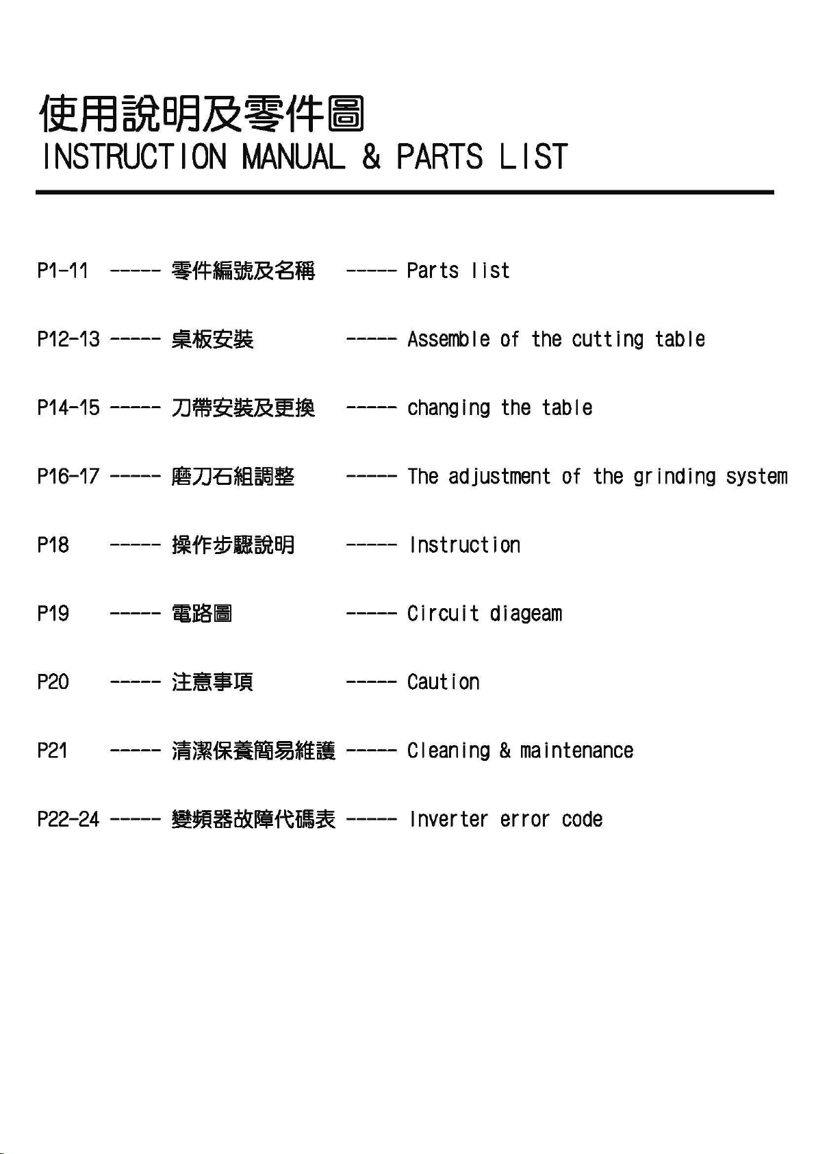
iiEFEJ~8~~~i~~
INSTRUCTION
P1-11
P12-13
P14-15
P16-17
P18
-----
-----
-----
-----
-----
3i~li~~:g~~
~~~~
J.J~~~~~~
~J.J15~~~
tifF~OmtBF.I
MANUAL
&
PARTS
-----
-----
-----
-----The
-----
Parts I i
Assemble
changing
Instruction
LIST
st
of
the
the
adjustment
table
cutting table
of
the
grinding
system
P19
P2o
P21
P22-24
-----
-----
-----
-----
sm111
tt~~m
~)ii*•fm~f.l~
~~~Oi~i~i~~
-----Circuit
-----Caution
-----
c I
-----
diageam
ean i ng & rna i ntenance
Inverter
error
code
Page 3
12
1
Page 4
P¥~
NO
i]fi
NAME
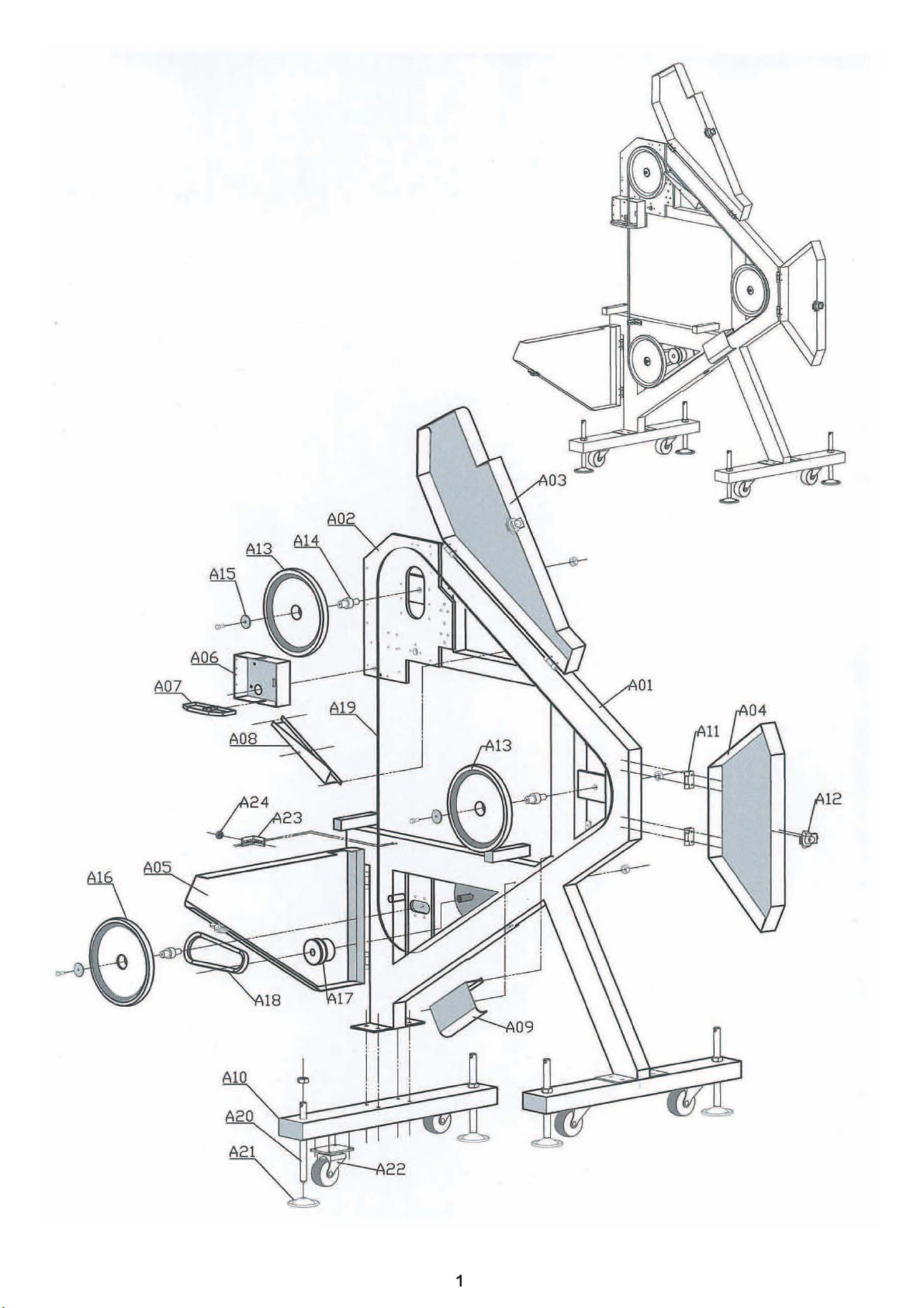
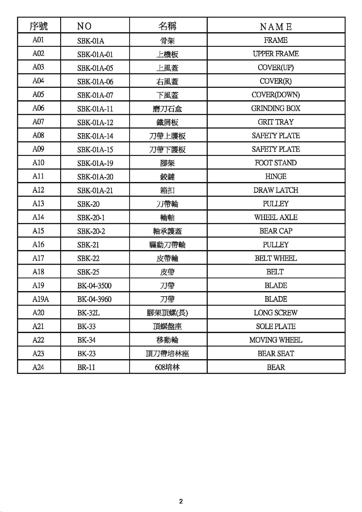
A01
A02
A03
A04
A05
A06
A07
A08
AOO
AlO
All
A12
A13
SBK-OlA
SBK-OlA-01
SBK-OlA-05
SBK-OlA-06
SBK-OlA-07
SBK-OlA-11
SBK-OlA-12
SBK-OlA-14
SBK-OlA-15
SBK-OlA-19
SBK-OlA-20
SBK-OlA-21
SBK-20
1t~
l:ltt&
1:&~
till.~
~&~
IJ7J5~
-~;fi
7J~l:~;f&
7J~~~tM
JJ§P~
~-
m1o
7]~-
FRAME
UPPER
COVER(DOWN)
GRINDING
SAFETY
SAFETY
FOOT
DRAW
FRAME
COVER
COVER(R)
GRIT
(UP)
BOX
TRAY
PLATE
PLATE
STAND
HINGE
LATCH
PillLEY
A14
A15
A16
A17
A18
A19
A19A
A20
A21
A22
A23
A24
SBK-20-1
SBK-20-2
SBK-21
SBK-22
SBK-25
BK-04-3500
BK-04-3960
BK-32L
BK-33
BK-34
BK-23
BR-11
-fltf
-~ml~
.Rif17J~-
&:tR'f-
&:~
7]~
7]~
Jmll~:m•c~)
m••~
:f$1f1.
rnn~f:~lfifc~
608!ffifif\
WHEEL
BEAR
BELT
LONG
SOLEPLATE
MOVING
BEAR
AXLE
CAP
PillLEY
WHEEL
BELT
BLADE
BLADE
SCREW
WHEEL
SEAT
BEAR
2
Page 5
3
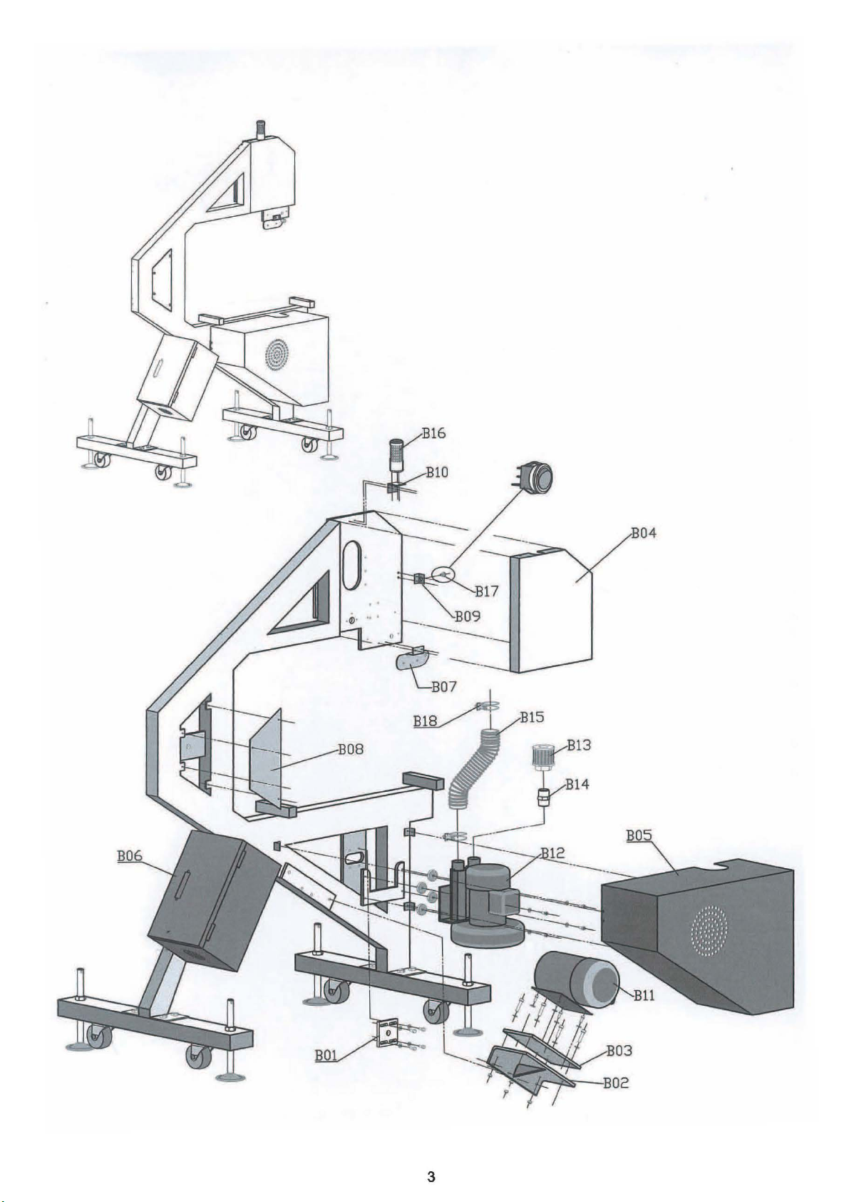
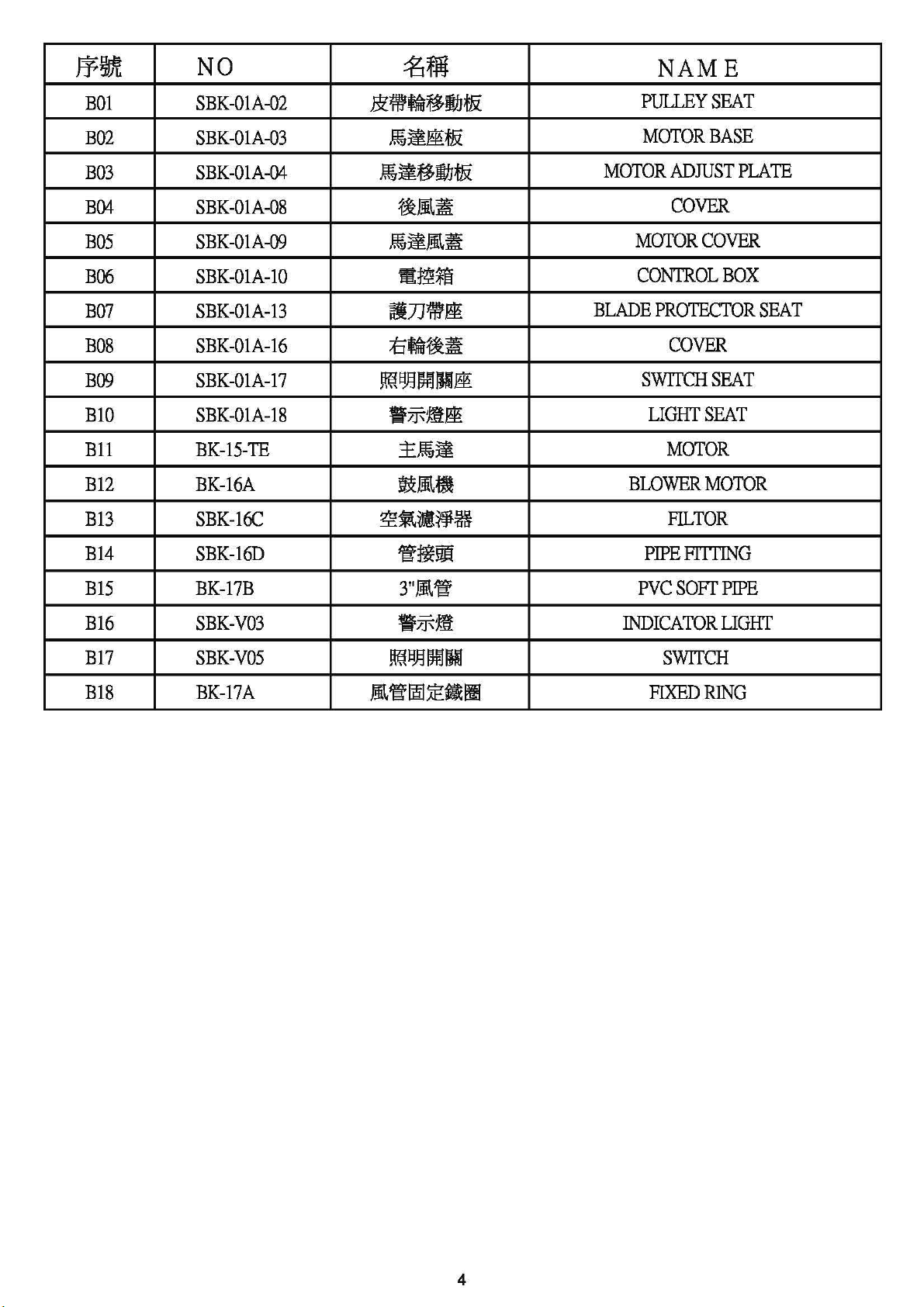
Page 6
P¥~
NO
ijflij
NAME
BOl
B02
B03
B04
B05
B06
B07
B08
B09
BlO
Ell
B12
B13
SBK-01A-02
SBK-01A-03
SBK-01A-04
SBK-01A-08
SBK-01A-09
SBK-01A-10
SBK-01A-13
SBK-01A-16
SBK-01A-17
SBK-01A-18
BK-15-TE
BK-16A
SBK-16C
El~~f$!1flif&
~~J~Ji
~~f$!1bt&
1&/lt~
~~Mt~
-~~
~n~m
:ti~1&~
~~~IHJ*
BLADE
e7]\mm
~~~
~Mt-
gg~-~~
PUlLEY
MOTOR
MOTOR
MOTOR
CONTROL
PROTECTOR
SWITCH
LIGIITSEAT
BLOWER
SEAT
BASE
ADIDST
COVER
COVER
BOX
COVER
SEAT
MOTOR
MOTOR
FILTOR
PLATE
SEAT
B14
B15
B16
B17
B18
SBK-16D
BK-17B
SBK-V03
SBK-V05
BK-17A
~~~
3"/lt~
e7]\m
~f!J31m!HJ
lt~lril~-~~
PIPE
FTITING
PVC
SOFf
INDICATOR
SWITCH
FIXED
RING
PIPE
LIGIIT
4
Page 7
ADJUST
C06
TIGHT
[04
01
5
Page 8
F¥~
NO
ijM
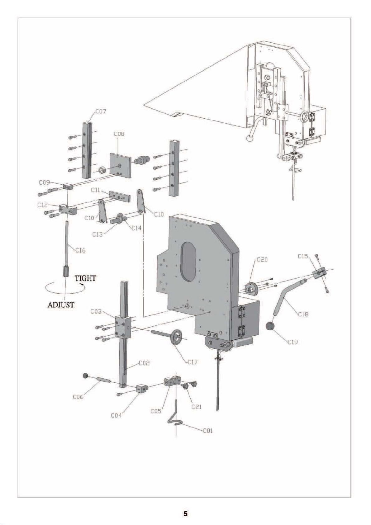
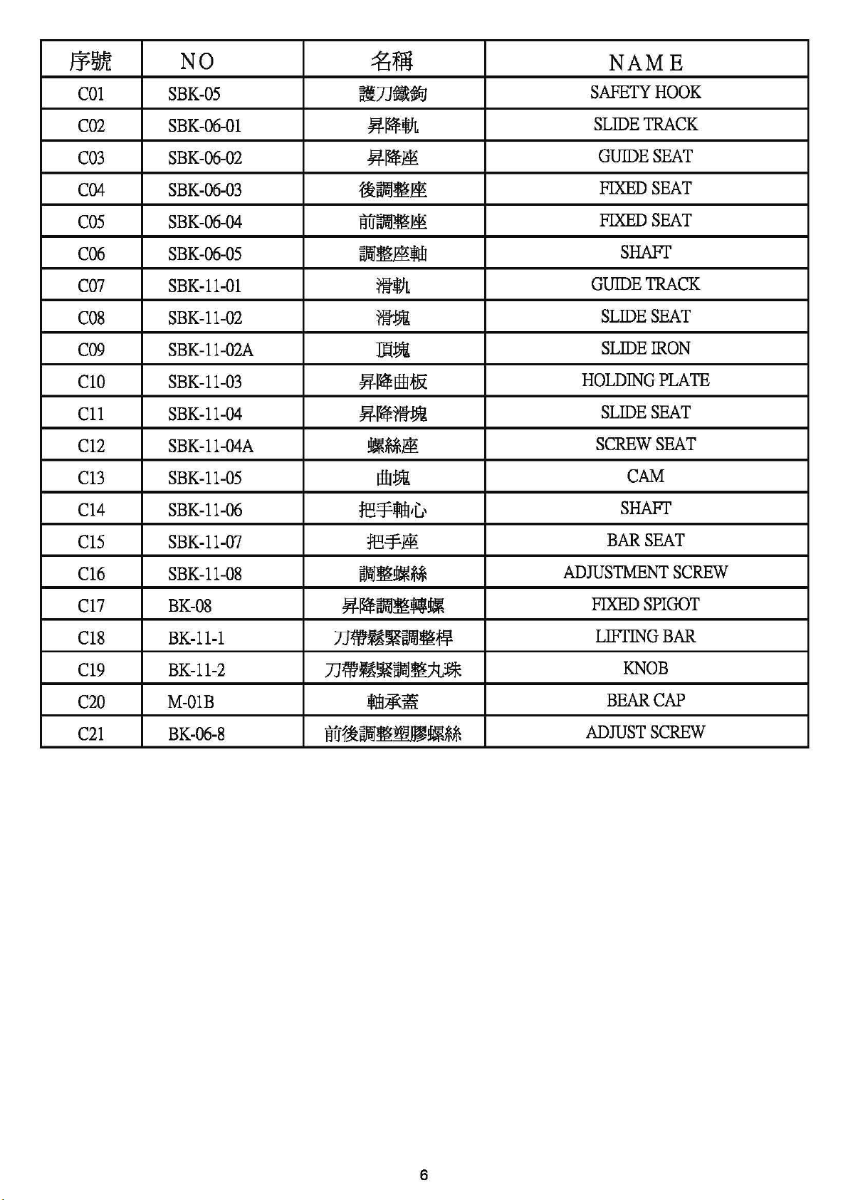
NAME
COl
C02
C03
C04
C05
C06
C07
C08
C09
ClO
Cll
C12
C13
SBK-05
SBK-06-01
SBK-06-02
SBK-06-03
SBK-06-04
SBK-06-05
SBK-11-01
SBK-11-02
SBK-ll-02A
SBK-11-03
SBK-11-04
SBK-11-04A
SBK-11-05
~JJitJY
n~fli.
n~~
~13~m
~u~~m
13~J*$11J
mfli.
~
:rnWi
:n~a±Jt&
:n~~
•**~
I±HWi
SAFETY
SLIDE
GUIDE
FIXED
FIXED
HOOK
TRACK
SEAT
SEAT
SEAT
SHAFf
GUIDE
SLIDE
SLIDE
TRACK
SEAT
IRON
HOLDING
SLIDE
SCREW
SEAT
SEAT
CAM
PLATE
C14
C15
C16
C17
C18
C19
C20
C21
SBK-11-06
SBK-11-07
SBK-11-08
BK-08
BK-11-1
BK-11-2
M-OlB
BK-06-8
~-'¥$liJILJ'
te
-'¥
~
13~91**
ADWSTMENT
n~Wl3~"•
JJ~~~Wt3~W
JJ1r!f¥~~wm~:tt~
qiffi*~
fri~~~~-**'
SHAFf
BAR
SEAT
SCREW
FIXED
LIFTING
SPIGOT
BAR
KNOB
BEAR
CAP
ADWSTSCREW
6
Page 9

7
Page 10

rr;~
NO
i5W
NAME
DOl
D02
D03
D04
D05
D06
D07
D08
D09
DlO
Dll
D12
D13
BK-28-1
BK-28-2
BK-28-3
BK-28-4
BK-28-5
BK-28-6
BK-28-7
BK-28-8
BK-28-9
BK-28-10
BK-28-llA
BK-28-12
BK-28-13A
P!JJE~
-(j/~\7\:fEJ!II-@
®/~\~
{ij}J~\~~¥-j!
~~~,~~¥-l!:tL~
tr:~~(~)
tl~~(~)
tr:~/~\(1£!f)
tl~~~'(IE!f)
B~608f€H%
~~-*'*
IDm¥-l!!ll*i
iNIDm~!m5E:W
ADJUSTMENT
GRINDING
SHAFf
GRINDING
CAP
SHAFf
GRINDING
BAR
KNOB
ALUMINUM
ALUMINUM
FIXER(L)
FIXER(R)
SHAFf(L)
SHAFf(R)
BALL
BEARING
ADruSTMENT
FIXED
SCREW
IRON
SET
BAR
BOLT
SEAT
D14
D15
D16
D17
D18
D19
D20
D21
D22
D23
D24
D25
D26
BK-28-13B
BK-28-14
BK-28-15
BK-28-16
BK-28-17
BK-28-18
BK-28-19
BK-28-105-GE
BK-06-8
NUT-M8-13
NUT-M8-13L
lli-M6-30
K-27
~IDm~!m5E:W
iN~~~-**
~~•m
~Wffl~
~~~
~~M~
~~~HI!
:ll(
-
ADJUSTMENT
r:rmnE
~~:m~•**
M8!flm
M8!flm
M6!11*-*
M7JE~J3.x¥-l!
IRON
ADmSTMANT
ADJUSTMENT
SPRING
SPRING
STEEL
RUBBER
BALL
RING
GRINDSTONE
GRINDING
SPIGOT
COUNTERSUNK
COUNTERSUNK
SCREW
HOLDING
BOLT
SEAT
SCREW
NUT
D27
D28
D29
D30
D31
D32
D3
3
BK-07
SBK-V06
SBK-48
BK-37
SBK-10
BK-lOA
BK-lOB
~7J~ii
LED~~~jf
=Bftm
=BJ€
lti£:11~
m.~
~-
~-
8
BLADE
PR01ECfOR
LEDUGHf
FELT
FELT
GRINDING
MAGNET
HIN
SEAT
BOX
GE
Page 11

EOS
E.lB
~
T
02
9
Page 12

ff~
NO
::g.w
NAME
EOl
E02
E03
E04
E05
E06
E07
E08
E09
E10
Ell
E12
El3
BK-01A-403
BK-02A
BK-02-1
BK-02-5
BK-03
BK-03-1
BK-12
BK-13
BK-14
BK-17B
BK-17C
BK-18A
BK-24
ll!ti5Efrj~
~t&
ll!ti5E~f&
~H~~
~Ml~
~H'ellll!ti5E~
~ti!il~~
3(~~~1'*
~1'*~*'*
3''~~
~~ll!ti5E~~
A_~U~
~f&ll!ti5E~
SCROW
SCREW
TABLE S
RUBBER
TABLE
LEG PLAT
ROUND
TABLE PLAT
FOR
P
VC
FIXED
BLO
WING
FOR
ETTI
NG
IRON
TABLE
PLATE
PAD
LEG
E
PLATE
E
TABLE
SOFT
PLATE
PIPE
RING
MOUTHPIECE
TABLE
HOLDING
E14
E15
E16
El7
E18
E19
E20
E2
1
E22
E23
BK-30
BK-30A
BK-31B
BK-31Y
BK-32S
BK-25A-1
IH-M8-65-F
NUT-3/4
BK-33
BK
-25-
2
m~~
~:3~
:±.m~moo~
~i~~oo~
HflP~JJ!~<~lD
~~~~1'ff&
ll!ti5E~**
7}7\frj~$§1
JJ!t"fi~
m•~t~*JR
SWITCH
N
AMEPLATE
KNIFE POWER
AIR
SWITCH
LEG SCREW
CONTROL
SCRE
WOOD
SCREW
SOLEPLATE
TRANS
MISSION
BOX
SWITCH
PANEL
W
CABLE
10
Page 13

Jr;~
NO
~f.lij
NAME
FOl
F02
F03
F04
F05
F06
Fa7
F08
F09
FlO
FDI
BK-19
BK-25-2
BK-25A
BK-26
BK-38
P-71A
V-03
V-03A
V-03D
SBK-V04
-A
L__j
7H§~'maNiJJE:SiKSS
'm-~~~CAT-5E
~!m~~
~U$'m~Jl~±TK80W120
lnJ)E~ilffij-Tfi6P
CrJ?ll~~
~~f*lfh*>*J*.
~~f*lfb*>*.t.~mm
f*~if*'
±INV
125-250VAC
TFB-10110A
lOA
FVR1.5E1S-2J
x1~TB25-6
AG-20(~
2*
10A(220V)
lP
TFB-ImiOA
@.)
8*8CMJ$1JjAC220V
TRANSMISSION
INVERTER
RESISTER
TERMINAL
EMI
FILTER
COMBINATION
FUSEBWCK
FUSE
BLOCK
FUSE
FAN
CABLE
BLOCK
COVER
lOA
FOI
F04
F05
II
~
f-------
~
I
-
F02
l
I
F03
-
1--
-P
;
FAN
~
oo-
+FlO
F06
KEY BOARD
I c:=:J
000
~
r
000
I \
ooo
\
El9
F07 F09
~
~~
I
DO
L
___
~E-1
FOB
~
~
_ j
9
F-
02
E-
16
11
Page 14

12
Page 15

j.
~&
~ * #
~~~
-t}t
E}i
1
2
Table
#~~t~(E02ff}JE!"J~tEz]~J)£~(E03)9=J~~\fL{lziJ~~~~~JE~~
ti::H'!f2f4~Ps~~**(E20)~~~
Mount
the
table
#~~!JW(E05)~~~~!JW~5EJ*(E06)
Mount
screws
asc::em
the
cutting
with
bolts
two
table
legs
(E18)
into
table
(E20).
(E05)
sole
bly
by
aligning
fixed
plate
(E22).
procedure
a
the
tapped
,
~#~~P~Jj~~(E
beneath
the
holes
table
of t
he
table
18)1DCAJJ
by
screws. Then
**(
E13)
line
rs
(E03).
U~MJ*(E
put frame
'
illUf:2
Fasten
22)
hold
ing
a
3
4
5
#~~
rg(E 1
(Ell) a
Slip the
hose
clamp
{R~~?JTW:
Adjust
#~OO~~(E14)~5E:tE~~t!T*~Tift#~~~~~t~*
Attach the swit
cable(E23)
O)~t~f~~~~~f~(B
blower
long
hose
(E1
0)
onto
(Ell).
~
Jj]JWJ~~P~Jj~~(A201StE
and short scr
ch
box
into
control
ew
(E
14)
panel
(A20&E
to
12)1St~ti
the
the
cutt
(E19).
air
mouthpi
18){£
18)
to
ing
J\~O~(E
ece
~t&ZfS~
prop
er
table, and plug
(E
12)
tight.
12)
)7
TIE~~~~
and
fasten the hose with
a
~(E23)t
the
connector
rg~)£~
~
_t
a
of
contro
l
a
13
Page 16

Al9
Cl7
Al.3
.
Cl6
A07
C16
ADJUST
D22
~
-
_CCil
14
Page 17

Installment
l
1m
:tc~~~~(
or
adjustment
E08
)lUl"-f
for
new
o
knife
Remove
lm~7JEif.lm~!l!!«~:l&~(
the
table
plate ( E08
).
D22
) •
:MLimM7JE
2
Unscrew
Jmn~~~f$!11!«(
the
plastics
screw(D22)
C17
):!&~ • lm'ifi7Jt.f*ll7T¥Ufi~t&~M~Im~
and
take
off
3
Unscrew
im-~~(
the
bolt ( C17 ) and
A07
)&7Jt.fifiS1J(
rise
up
the
COl
knife
)lf5ltB
4
Take
out
the
grit
tray ( A07 ) and
safety
wire ( COl
the
grinder
guide
if.(FOl)lCil"-f
assembly(FOl).
to
highest
o
).
o
o
position.
im7JtffiJ~~~m:fll!(C18)ftlf
f
)E • fj!7JtffiJ.(Al3)~"-f
5
Press
down
the
Jm~
7J
1/W(
A19~A19A
adjustable
driver
of
knife
tension
):t&:tE=~nlflfljj~IJ$00
(Cl8) to
6
Mount a new
f!:lt7J1/W(
knife ( A19
A19g\GA19A
or
)~~ • :ML~g1J1Ef$7Jtrf~m!i!!«**(
A19A ) ride
on
three
pulleys
7
Test
the
f&!{ijm
knife ( A19
1-4~tv.w~m~JJ.i
or
A19A)
tension.
~
#t&n~F¥~§1
..
8
Install
by
step
1 -
step
4.
o
lower
•
:MLJm
7J
and
pull
the
knife
wheel
tfW~~~(
up
the
C18
driver ( C18
C16) o
(A13).
)rtiJl:iii
o
).
15
Page 18

* * *
* * *
16
Page 19

X
X
0
1
2
3
~]]~
l!f7J~Ilfli!~(D22)t&Ji
Mount
~=ilrr&ruW~n~l«~<Dtt> , ~JJE<D2t)
~gfm~~¥TJ7Jf/1(A19~19A)
Adjust
grinder
1E~lf7Jf/1(A19~19A)}J~Jmtl~il
See
the
grinder
the
screws
stone
attached
(D21)
for
adjusting
system
of
touch
-~·1J!l~!Y~1>t~
Grinder
t
holding
grinder
(D11)
the
the
knife
knife.
:i&A.J!!7J~If.~(D26)~~
(D26)
o
to
correct
(A19
Wheel
and
screw
position
or
A19A).
it tight
to
let
o
the
0
17
Page 20

#h
1-'F
ffi-
~lftl
~
aJl
Instruction
~5felil;xE*$t~f.£AC220V
1
Make
sure
the
voltage
~J.E:$;t&{IDJjfi¥J
rr-RUN
2
KNIFE
RUN
STOP
~~J!~~~1'Fmrt&_ti¥J
~m
3
A
V
~1'F00t&..t.
4
FUNC/DATA
key:
key:
w v
key:
key:
.n
l'iJ-at!7J1f{¥im$$
key:
Connect
Start
Stop
.n
m~1J£7J~~gr
Increase
Lower
the
IT"RJNC/DATA.n
key:
is
rr-KNIFE.n
the
the
knife.
the
knife.
the
speed,
speed,
Select
•
ML~m$t*~H~¥U~m*-*'lmiBI
AC220V,
•
connect
~il:(E-16)
~}E
w
STOP
the
•
.n
power.
w A
.n
ll!mffl1Jonm~gr
,
ftfWJ{$
maximun
minimun
ampere,
to
60HZ.
to
OHZ.
J1Jfj~-1U11J~7J\~
power,
or
power
fj!;tt:'M$t~A.~~B
l'iJ-at!7J1ff¥W
o
HZ
voltage.
0
wire
to
Jtim$$ o
•
ft~~$
§ •
•
fJ§~,~~~~_t
NFB
and
'WJJtlD
: 3(!tf
connect
•
¥J~IE~B~1'Pttl.l¥1
6oHZ
~
:W$
the
0
o
ground
~
~
wire.
...
~
o
LED~~!ij~,~JHt~m
s
~umJ~C
Press
~m:$;t&{IDJil®
6
AIR
fabric
~fT'mlml:trJ*4~
7
Put
0
KNIFE(E-16)
key
(E-17):
can
be
moved
the
knife
guide
Turn
rr-
KNIFE.n
first,
and
press
w
AIR.n
lightly
•
m!~~nm*Mmr~m~m~woo..t.
on
~<E-17)
on
the
blower
on
the
the
fabric
when
~(E-16)-at!;tt:'ClJj~
LED
lighting
m~nm~~.
and
air
layer
control
is
formed
switch
,
¥J~mLED~I!I3~fliU
(B-17)
~*t~~:n~-at!:trJ*4~tJJR
between
to
control
fabric
and
table
table.
0
cutting.
kEY BO
AR
D
I I 8
@ @ 8 E
-1
® MS
the
9
!m
!IIJ(B-17)~
light.
0
~
~
surface
so
that
the
E- 16 E- 17
I<NIFT
18
AI
R
Page 21

~~~lll
.....
co
p
OwER
NFB 5
?+
220VAC
10
N
L
Gl
'+-
CIRCUIT
~
DB
l 1
Pl
r--------~
FUJI
RJ4
DB1
lfG
DB
~
L1
L2
30220VAC1
KN
IFE
F
USE
10A
~~~±=====Lll
L
lP
h
Pl
L2
FV
R-EllS
1.
5KV/ - 2HP I I
CONNED
l
P<+ N<-
L3
N
:~V
H Ml G n
MOT
OR
TOR
u vi
v;
JGl
v;
p S
~
____
DIAGRAM
KEY BOARD
- _
KNI
L2
""'
_I.LT-'1
~========J_Jl~--_j~
CICCI
0 0 0
000
FE AIR
wl
1--
L1
~
......._,..r--
N Q
Sw 2
~
......
o-
~~
L3
t-...tJ-+-~
Sl,/3
1r~~~
"t--
L4
..
o
\:
L3 N _
~
NF
r
Lll
L...---
___
l N
L.
I N I
l
0.----J
_____A,'---'0-
~
L.
1 I T N AIR M
I
T
['-----1
2 N lu
......
l-;;1
1022o
vAc
OTO
R N,,_._
l M 2 F A N
L2 G
·~~
-
l?.:-.--~
~~
~
Page 22

Specification of
Band
Knife
Cutter
~~~Model
BC-700 BC-900
I 1'Ffiiiilifit Table Size ( rnn) 1800x1500 2100x1500
Ifl:fli'&Hl(1iJ~)
Table Height (Adjustable)
W~ArmSize
BJH~~
8ft~-
~-R.
'f
§~R.
JJ
Minimum Width
Machine
Machine Gross Weight
Complete Set Dimensions (
'f"Packing
1JRi
R.
'f
Knife Size ( rnn) 3500xlOx0.45
JJ1Nlif!Jf.l~/j\J[}i
fli!Jf.li'&JI
~~Voltage
!m$
ii:;ktJJ!!!itl/¥HfMax.
~~~~fM
Speed Control
11!1Jf.!M£
Drive Motor
The
applicable restriction
(Frequency
~M.~ii
BitJJ:ffi~
~Jl:ffiflBitJJ~RtiJ
(rnn)
(rnn)
Net
Weight 240kg 260kg
700 900
381kg 428kg
rnn
Dimensions (
of
the
Knife (
rrrn)
Available Height
rnn
)
)
2210(L)x1500~x1720(HO
1670QL)x970~x20800H)
¥m
Frequency
cutting thickness ( rnn) 180
< 1iii'!l)
(Variable)
(tiM)
Conversion)
Blower
Motor
Available Fabric
of
the
special fabrics
CD
fi!1'14-ff:ffi2"
® fii1'11J1Bl4'itl1'il2"
@
fi!miJIBll"
@
IDVCBll"
®
fi!~
PX.Bll"
H :
j..j,J:.filf~fi!WflitJ
j..).
j..).
j..).
"'F
0
.......
=m
-~
-ltittt6,lX1i!JZii:ffifl
General Knitted, Woven Fabrics
j..).
"'F
o Rigid Jean below
j..).
"'F
"'F
o Rigid Plastic leather below
o Rigid PVC leather below 1" .
"'F
o Rigid synthetic leather below 1" .
o Note: All
850--950
2490(L)x1500~x1720(HO
2270QL)x970~
3960x10x0.45
2.5
8"
Single Phase 220V AC± 10%
50Hz
.......
60Hz
1060 m/min (
Q.-..60
Hz)
Three Phases 220V I 750W
Single Phase 220V I 180W
2"
.
o Rigid rubberized non-woven fabric below 2" .
I"
.
of
the above has turning restriction.
x 19400H)
~11=1Jlt
Bc-1oo1
• o
31b.&ti1lM
9oo~
~u
t~fl:elt~:MMBtJJ
MtJJ:ffi~"'F:n~~t•-~m
o
1'1l~
.-fJe~n:~AAtJJ!!!iu
JJ11MiiJ..;i.BitJJ~HI1Pfl
The major operation mode
of
all,
move
the fabric along the template shape
Operation Mode
cutting pieces. First
desk
after air flotation motor
locate
it
and
then
trimming for small fabric; moreover, it
fabrics.
"f=
~
lf:Ultlft'tffiJ ·
1
Lower
the
knife
~tey~~lf:Ultlf~·~~-~~-·
2
Disconnect
~ffl~~~W~·li'R~-~~H~m~M·
3
Press
I~A~~ffl~IT~ffiJ·~~~m•w~~~·
4
It
is
the
reco
mmended
the
power
power
Ji'ROO:lii7Jtmmt.&¥U®~H~:!ii:!;OO
guide
down
to
the
table
supply
to
put
supply
button
on
cable
from
off
if
stainless
the
stee
surface
power
the
outlet
l mesh
for
if
supply
gloves
safety
the
cutter
is
interrupted
for
,
i¥3E.A~~7Jtm~h
.
is
safety.
!!!itl,Ml!!iD
I
.mihll$!¥.~ilm
J:.n~aJ..;I.•Jt~fil!lte~:AE'lllfli!ltJJ
o
JJ:ta~{g,1iJf«MB'J'1'il~•:iE((.JflfttJJ!!!itl
o
of
BC-700/ 900 series,
put
a paper
under
started.
By
the way, a
can
~
Caufun
attaching
the
fabric to
mo
adjust tbe knife rotation s
F'i
~
LED ligb.t in cutting
make
the fabric move
ld
or rigid template
by
hands to
.±
• M
PM~•
I
uetJJ!U:ffifl~:ON±~iiDJ:
•
is
needed
cut
This
peed
to fit
J!J
Iii
mn¥~
~
fijj..j,
~lb31h1'il~
I
JJ:t9~~1iJ&fj•
area,
is to fine cut smal
and
on
model
tum easily
the fabric
can
for
on
to
also do mien
cutting
varioUJ
thl
we
•
not
being
during
operated
operation.
for a long
period
of
time.
20
Page 23

~mm~~~oo~~~~~~~~~~~·~•~BI~%-~m~o
1
Remove
cloth
waste
on
the
table
at
regular
intervals.
~mm~•~~<A-07)~~~-~~~oo . ~•
2
Remove
JEm~1!t+e~<D-3o),
Clean
3
Change
5Emm~~~-1J~<B-13)<~P9M,
4
Clean
Change
jtlfUl7Jttf~?*~lf.f
1
If
l.:ft1!t·~~S~AC220V
Check
the
grit
the
felt
it
if
the
air
it
if
knife
the
from
the
(D-
30)
extremely
filter
and
extremely
is
damaged,
voltage.
grit
tray
once a week.
m~r5t5&~1Jn~na.
and
fill
silicon
dirty.
cloth
waste
dirty.
~,
,
~ft<Wfff1U~JJH.~JJ!:ft1!t
check
b)
by
o
oil
once a week.
inside
Mt
steps:
~~-1J~M:m:¥5~1f.f~J!~,
the
case
-ti
~~Jmm~~~
llm¥5t51f.f~£~,
which
is
under
the
table
once a month.
Maintenance
o
0
~~~~m~~~
••~ffl!I.FJ~~~~
0
0
2.:ft~~*-*'~slflm
Check
3.:ft1ftl!I~~(F-06)~N~Jl
Check
4.:ft1!t~tm~(F-03){g-2iii1'FWt&CE-19)~st&~
Check
5.:ft~tt~:H~s~t&~ft~
Check
6.:ft1!tKNIFEf1iil:lm!BICE-16)~Nt&~
Check
7
.:ft1!t7JtR'fJ.t;~(B-11)~St&~
Check
amt~~~?*lb1'Fif.f
2
If
the
l.t9l~~~~:S:~AC220V
Check
2Atitf~df~*-*~slflm
Check
3.~~AIRtiemlmiBICE-17)~st&~
Check
4.:ft
Check
the
fuse.
the
wave
filter.
the
inverter
the
error
code
the
switch
the
knife
blower
the
voltage.
the
fuse.
the
switch
i!t
5WitJ.t;~(B-12)~
the
blowing
for
motor.
motor
for
o
o
o
and
control
of
inverter.
knife
·
~ft<~""f1U~lJi~lJi~~
is
not
working,
blowing.
motor.
power.
o
0
:S:
t&~
panel.
·
:fifu~ft<~~ttff!ML~F~
o
o
o
check
by
steps:
0
o
o
21
Page 24

;!t.Jlf~
Error
code
Description
-f*"il3/J~6
~~3!1'1/l
Detail
OCl
OC2
C3
QUI
OU2
OU3
~-~1*~
Overcurrent
protection
~~
Short
-circuit
protection
!:tit!!~~
Ground
fault
protection
~U-f*lii • WJtU~ o tzD5F!:Mim~Df!J3ia~j(I¥.JU!flf
Overvoltage
protection
~ZSJ~~ffifij
Stop
the
IZSI!Iitl:BUI¥.J~ij
Stop
the
short-circuiting
-R:tE~I1J~~•te~I¥.JW~i3
~f~!rffftlmm~
Stop
the
the
output
tum
ON
~tll:BW:mttf:11YJUI¥.J~::k-mJM
Stop
the
phase
protection
rm~•~-1*~1/Jfr
inverter
inverter
inverter
the
inverter
200
is
in
circuit.
inverter
V,
800
not
output
output
output
to
protect
f~~-~-f*mlbf'F
to
protect
the
output
•
-srn~~~rr-1*~
to
protect
This
protection
without
output
assured
VDC
upon
for
three-phase
if
extremely
•
the
the
circuit.
the
is
removing
detection
~
Jt~!111~
inverter
inverter
0
inverter
effective
the
ground
( 3
~EI200V
of
an
400 V class
large
AC
0
from
an
overcurrent
•
1¥
_rtg~
from
overcurrent
rm~¥.J~mmt
from
overcurrent
only
during
fault,
:
• w
startup
this
DC400V
•
overvoltage
line
condition ( 400
series)
in
voltage
is
due
o
due
to
Jt~~~ 0 :tEW:till~
due
to a ground
of
the
protection
•
3~EI400V
J!U::f11~1*lff
the
DC
applied
to
overload.
a
fault
inverter.
may
If
not
work.
:
DC800V)
o
VDC
for
three-
link
bus.
This
inadvertently.
in
you
LU
Lin
OPL
~1!tl:BW:mttf:11YJU~~fl£
'WJtU~ o {B~ • ~~
j;:_MJE-f*~
Undervoltage
protection
!litA.~~EI-1*~
Input
phase
protection
Ml:B~fEI-1*~
Output
loss
phase
protection
~~l:f1-~o
Stop
the
inverter
level
(200
VDC
for
However,
voltage
~tl¥UMA.~~EI
ttr
NP{j!t£!1itA.mR:~EII¥.J'Ift?5?.~
~-~~l:BQiRfEI
loss
Detect
from
voltage
reactor
~1!fl:f1~11J~~~tpi¥J•te~~I¥J~~·{¥Jt~~o
Detect
the
if
data 114
drops.
•
i3
rmu~J::tiWJ~!lffffi¥.Jff!:JJi3
input
phase
undergoing
unbalance
is
connected
breaks
inverter
in
inverter
output.
( 3
~EI200V
1
F14=4
output
when
the
three-phase
11
or
5
is
selected
• W
Jt~~~ o ~Jjj1J~-aJPJ1$jjJtffi~m~~~EI:®G~EizFd1::fZJS
•
~~ffti¥1~-~~~PJNfftW:~-mm~~
DC
200V,
for
J!,IG5J
link
400
Fl4,
ffi!i
bus
voltage
VDC
no
rmm•
:
DC200V
•
NP{j!W:1fittf:1Fd1~11Jiff~
for
alarm
0
• 3
~EI400V
drops
below
three-phase
is
output
:
DC400V)
the
undervoltage
400 V class
even
if
the
series).
DC
link
•
•
•
-tl1.
bus
-tl1.
o
loss,
and
stop
the
heavy
and
to
stress
may
the
output
that
damage
inverter,
wiring
inverter
may
the
this
output.
be
caused
inverter.
function
at
the
start
This
by
input
If
connected
will
not
of
running
function
phase
load
preven
loss
is
detect input
and
during
ts
the
or
inter-phase
light
or a DC
phase
loss
running,
inverter
if
any.
stop
22
Page 25

OHL
dbH
~H~
Overheat
protection
J-Jm-~~~J.tma~Jltt~;fO~~
Stop
the
inverter
fan
failure
~D5fH'f·$ff#Jmtr~~llU~~
*~'aJ!f~®iMtJJtl~llU
Discharging
braking
*
resistor.
Function
or
overload.
and
codes
output
inverter
must
be
upon
operation
·
tti!fte~~Jl®U
detecting
•
~
•
are
set
corresponding
• w
excess
JtJvr~IIJ{'F;fO~~UmtJ{'F
~)E)jjfjge§
stopped
to
heat
due
the
sink
temperature
o
to
overheating
braking
resistor.
in
0
case
of
Jt~~u
o
of
an
external
cooling
OLU
OH2
OLl
OL2
~i®fful:B1!7frt;f0]7q$Utt1t
~~-f*iM
Overload
protection
~MJi~
Stop
temperature
over
51--$tf~~
flu
A.
External
alarm
~i®~lftiffuA.Fs~
Place
input
~i&tm.:r~m3mijg~~JE:WJ£:~~3.
·:ff~~$fBIIIP"1-f*Hffl~~o
1!-T~Il-3
Electronic
thermal
overload
·:ff~~$~~pi\J-f*~~Wffl~~o
*1liP.J.~1'FW.J..&~Jf,ffm'M~
In
the
accordance
-
Protect
-
Protect
The
operation
0
the
inverter
calculated
the
preset
value.
the
inverter
following
with
general-purpose
inverter
level
output
( THR)
in
alarm-stop
cases,
the
electronic
motors
and
if
the
from
the
the
inverter
motors
over
thermal
•
~ll!GBT
Insulated
output
·WJt.M~I¥J-¥llo
state
Gate
current and
upon
ll\Jff
Bipo
lar
receiving
~it~~
B®~liir.)j{
Transistor
temperature
•
(IGBT) int
of
digital input
0
o
stops
thermal
over
the
entire
time
running
overload
the
entire
frequency
constant
the
motor
protection
frequency
range
can
be
set
to
protect
setting.
range
(FlO = 2.)
by Fll
mte~itft!~
•
1¥
Jt
ernal
inside
the
signal
(FlO
and
THR.
the
= 1.)
Fl2.
inverter
motor
is
in
OH4
Er1
Er2
Er3
PTCY11m
PTC
thermistor
~a·r:~
tt~m
Memory
error
detection
Nkf'FOO;f.&
~rn~m
Keypad
communications
error
detection
CPU~'M
CPU
error
detection
1lJ~~c~m·WJt~~3·~~~~
il#ff-
[ c1 l - [
11
l
zrm~~PTc
~~~ll • ~5Em1firr£t&..t®miHI.&mijg
0
e§o
A
PTC
thermistor
Connect a PTC
and
slide
switch
U-m$tmJ;fO~A.UJeytt1!t~!!l
WJtl!~3o
The
inverter
memory
~~~
~U~1'FOO;f.&Wt!~U*IIFm$J~rn~'M
The
keypad
~~te~~~51Jte$JCPU
If
this
inverter
the
inverter
function
error
OO;f.&C*R
during
input
stops
thermistor
on
the
interface
checks
stops
is
detected,
by
memory
~
detecting a communications
operation
detects a CPU
stops
the inverter
the
inverter
between
PCB
data
after
the
inverter
~)~~Jj]fj~~OO;f.&C
using
the
standard
~'M
error
or
output
for
motor
protection.
terminals
[C1]
and
[11]
and
set
accordingly.
•
tt1!ttB~c·f:IMI¥J~'M
power-on
and
when
the
data
stops.
~~~)~~~
• W
Jtt!
~U
o
error
• W
ll::~~
LSI
error caused
keypad
3
between
or multi
o
by
noise or
the inverter
-fun
ction keypad
.
the
•
is
written.
some
function
other
codes
If
a
·
and
the
(optional).
factors,
23
Page 26

Er4
~ft:JR
~w:fi.-m
Option
communications
error
detection
U~Wff:~fmfliJey
Upon
card,
detection
stop
the
of
inverter
an
•
~ff~~!fiJh~~*lll¥1~rn:fi.-m
error
in
the
communication
output.
between
•
Wll:~~~
the
inverter
and
an
optional
Er5
Er6
Er7
Er8
~DaR~
Option
detection
~IV1'P~1ft
Operation
protection
1ft
error
U~~ff:~fmfiiJey
When
llPU~flffifril'Uffi~tfHDJf~~~
-~ • ~fMtt~~Wll:
Pressing
if
the
communications
~~:fi.-m
Tuning
error
detection
Rs-48s~w~m
RS-485
communications
error
detection
~~~mm~$ · ~rr~~ruc
Wll:g~o
During
abnormal
~1'POO~I¥Jil!~a~~s-485
~·ml/J\~mo
When
designed
displays
an
option
the
inverter
tuning
condition
the
inverter
for
an
error
key
is
of
the
card
has
on
the
running
Oink
operation).
motor
has
is
connected
keypad,
code
er8
•
dft:WFOOJfti!U~m
detected
o
keypad
by
parameters,
been
an
error,
this
C~ll:U/f\Er6
forces
any
detected
the
inverter
run
commands
After
the
motor
,
$BT
if
the
tuning
in
the
~rn~~JTJmt1~
to a communications
detecting a communicatio
• w
ll:~~~
function
•
~tfF~1'Ptmt&I¥JSTOP
stops
o)
to
decelerate
given
via
the
terminalsor
stops,
the
inverter
,
~~*B*I¥1~-mffif
has
failed
or
tuning
result,
the
•
~~rr~w~-mffif
network
ns
error
via
stops
.
o
the
inverter
and
stop
issues
has
aborted,
inverter
the
the
inverter
output.
the
alarm
•
or
stops
• w
RS-485
motor
even
er6.
an
its
output.
ll:~~
port
output
and
ErF
ErP
ErH
Err
!Xm&ffif
~-~:fi.m
Data
save
error
during
undervoltage
RS-485
~m~'m
(~ft:l{tf:)
RS-485
communications
error
detection
(optional)
iij!fll
~-m
Hardware
m•t&~
Mock
error
alarm
.XmE-f*~lb1'Pffif
If
the
data
could
the
inverter
U~llli{tf:RS-485
•ml/J\~mo
When
the
displays
inverter
communications
displays
~iMEIJiiJU~!n-1Jj£;t&QJGWOO--FI¥J~~::f
OOI¥J~ffif·wll:~~~·•/f\~mo
The
(control
board
detected
.m~t&~m~ · ffiJU~tBV¥~
Simulated
an
inverter
PCB)
(interface
.
alarm
error
is
stopped
and
•
tlD*~ff~f*ffU
not
be
saved
during
the
alarm
~ffi-F-~KM~I¥J'r1ir5l'F
is
connected
card,
detecting a communications
code
erp
.
when
poor
power
printed
PCB)
or
option
is
output
to
check
activation
code.
to a communications
connection
circuit
card,
or
the
•
~Uml/l\~-m
of
between
board
(power
short-circuit
o
fault
sequence.
o
the
undervoltage
•
ft~IT~ffi~'ntffif
network
error
stops
~ • ~Jl:BliffifT
the
control
PCB),
between
protection
via
an
optional
the
inverter
printed
interface
terminals
printed
function,
• W
ll:~~~
RS-485
output
[
13
circuit
l - [
and
11
board
circuit
[13]
and
[11]
l
is
24
 Loading...