

Page 1

ASP-PTA100
使用說明書與零件圖
ORIGINAL INSTRUCTIONS BOOK & PARTS LIST
Page 2
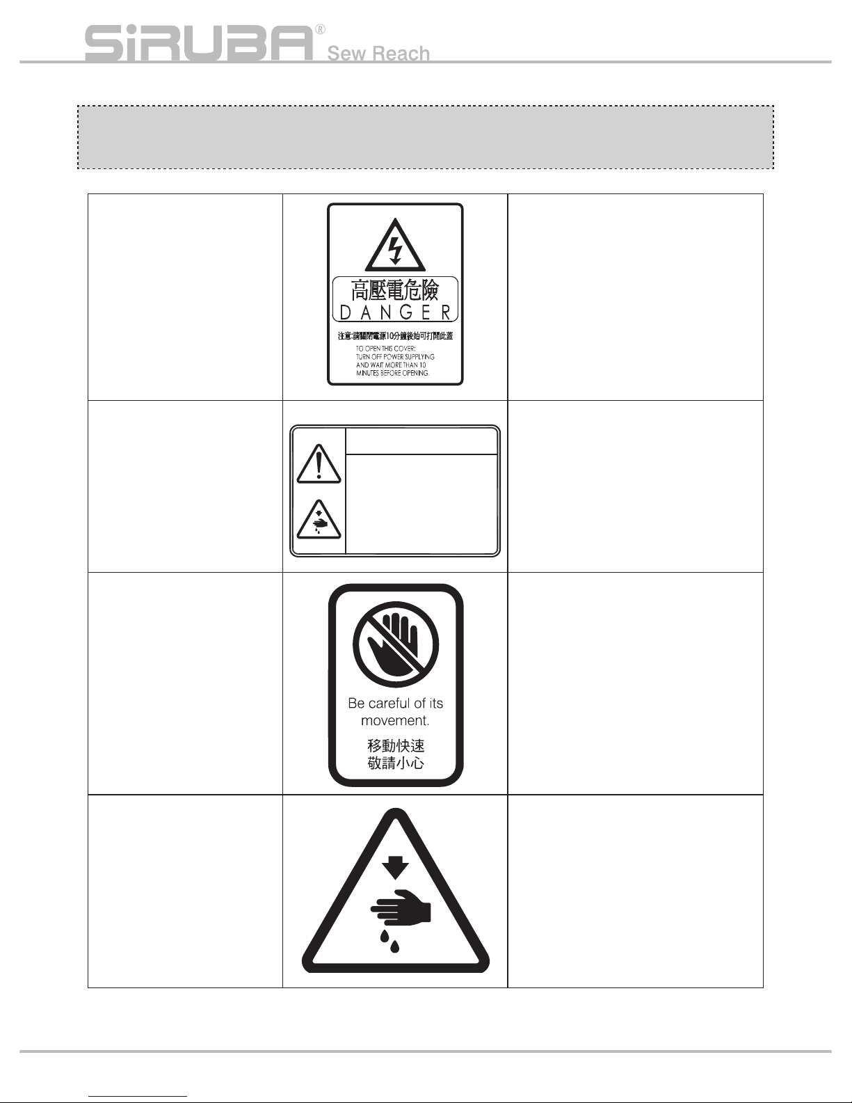
警告圖案表示
INDICATED THE ALERT
PICTORIAL MARKINGS
高壓部位
HIGH-VOLTAGE POSITION
務必關閉電源 10 分鐘後始打開電控
箱蓋子
Be sure to turn off the power and wait
till 10 minutes before opening the
control box´s cover.
高速運動部位
HIGH SPEED MOTION
POSITION
謹防工傷事故
In case of industrial accident
高速運動部位
HIGH SPEED MOTION
POSITION
謹防工傷事故
In case of industrial accident
高速運動部位
HIGH SPEED MOTION
POSITION
謹防工傷事故
In case of industrial accident
CAUTION
機械作動部份請注意裝上
保護裝置
穿線、換線、 調整、清潔
時請注意關閉電源.
Moving parts may cause in jury.
Operate with safety devices.
Turn off main switch before
threading, changing bobbin and
needle, cleaning etc.
ii
Page 3
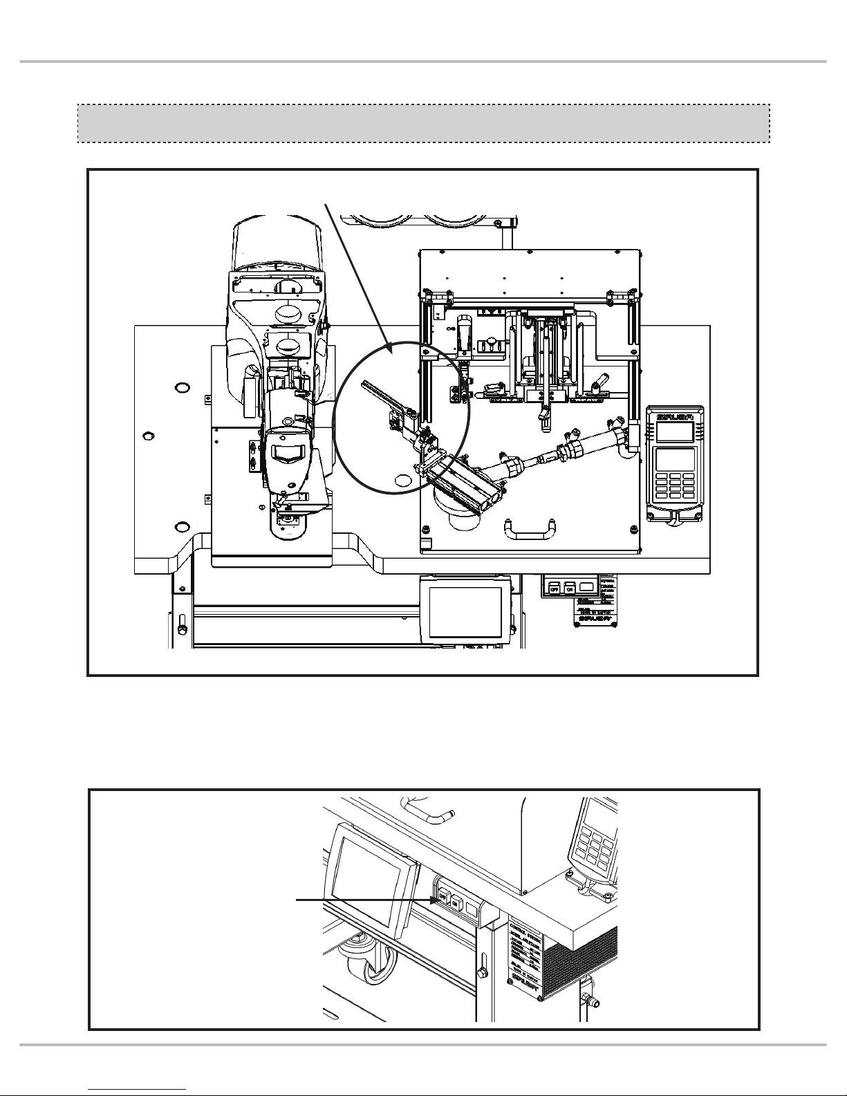
安全注意事項
SAFETY PRECAUTION
1. 機器在運轉與開關機時,請勿進入該區域
內。
2. 為了保修,檢修卸掉罩蓋時,必須將電源切
到 OFF。
1. When machine is in process, do not enter
working space.
2. When in maintenance, make sure turn off the
power before inspecting and removing the
cover.
電源開關
Power switch
機器動作範圍 ( 區域 ) Machine working space (region)
iii
Introduction
Page 4
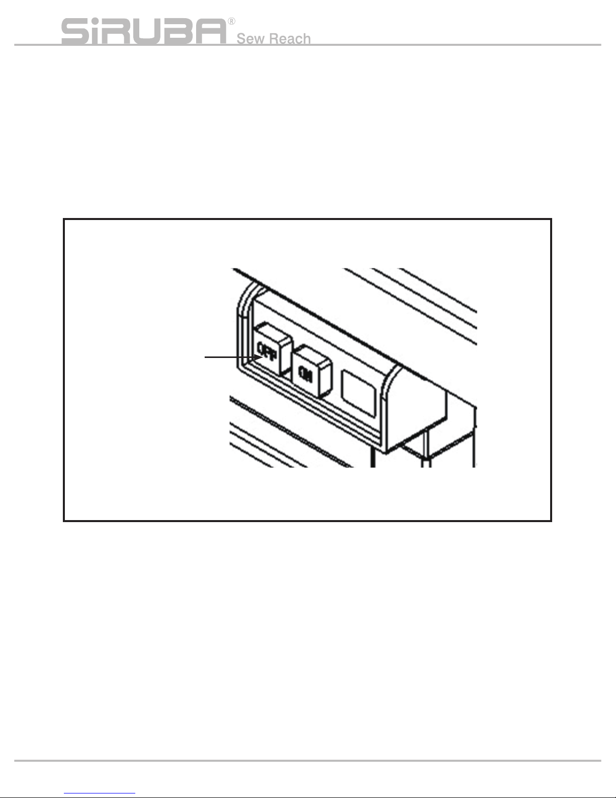
3. 在有危及人體的高壓電處,貼有觸電危險警
告標記。在貼有本警告的電器控制部位而需
要保修、檢修時,打開罩蓋僅能由專業的電
氣技術人員進行。
3.In working place with high voltage power,
there is warning sign. When maintaining
machine control part with this warning, open
the cover and only process by professional
electrical engineer.
4. 機器運轉時,有必要馬上停止機器的時候,
可以按下緊急停止開關。
4. When we need to stop machine in process,
we can press emergent stop button.
5. 電源線、氣壓管線需確實固定安置,不可散
落在地面,以免人
員絆倒而發生危險。
6. 為了生命安全,在任何情況下,不可將電源
地線拔掉運轉機器。
7. 打雷時,為了安全要停止作業, 切斷電源。
8. 離開機器工作地點時或工作結束後一定要將
電源開關轉到 OFF。
9. 機器運轉下,不可卸下罩蓋類。
5. Settle down power line and air line certainly.
Tools should not spread on the floor or
stumble workers in danger.
6. For the safety of life, do not disconnect
ground wire in any situation when
processing machine.
7. When in thunder, cut off power to stop the
process for safety.
8. Must t
urn OFF the power when leaving
working place or finishing working.
9. When processing machine, do not remove
the cover.
緊急停止開關
( 電源 OFF)
Emergent stop button
(power OFF)
iv
Page 5

索引
INDEX
頁 /PAGE
規格 SPECIFICATIONS 1
安裝 INSTALLATION 2
運轉準備 OPERATION PREPARATION 3
操作面板與啟動開關 OPERATION SWITCH 4
車頭參數設定 MACHINE HEAD CONFIGURATION SETTING 5
紙卡安裝與對位 LABEL INSTALLATION AND ALIGNMENT 6
錯誤代碼 ERROR CODE 11
異常排除 TROUBLE SHOOTING 12
動作模式 MODE SELECT 20
按鍵說明 BUTTON INSTRUCTIONS 23
操作說明 OPERATION INSTRUCTION 24
參數說明 PARAMETER INSTRUCTION 27
故障排除 TROUBLE SHOOTING 31
控制板 ( 一 ) CONTROL BOARD (I) 32
控制板 ( 二 ) CONTROL BOARD (II) 33
I/O 板 I/O BOARD 34
出現錯誤代
碼 E01:
通訊故障
ERROR CODE E01: COMMUNICATION ERROR 36
簡易維修流程圖 SIMPLE MAINTENANCE 36
零件圖 PART LIST 38
氣壓流程圖 AIR PRESSURE DIAGRAM 52
氣壓裝配圖 AIR PRESSURE ASSEMBLY DIAGRAM 53
路線總圖 CIRCUIT DIAGRAM 54
v
Introduction
Page 6
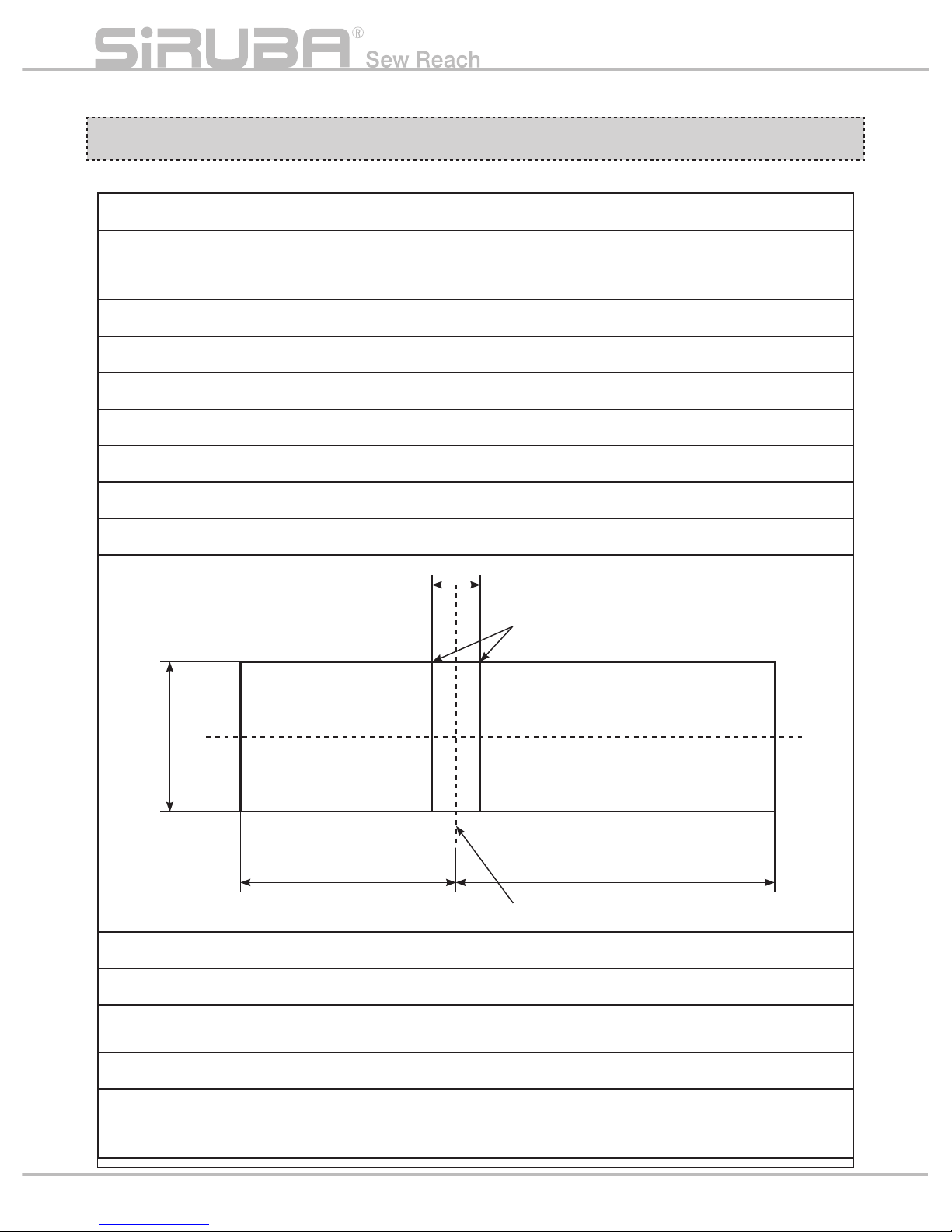
規格
SPECIFICATIONS
型號 Model ASP-PTA100
搭配縫紉機機頭
Collocation Machine Head
平縫(高速電子套結機)
lockstitch (high speed electrical bartacking
machine)
車縫速度 Sewing speed 最高 Max 2000 SPM
使用針型 Needle Type DP×17 #11
紙卡單邊長 Label Length 35~65mm
紙卡寬度 Label Width 35~65mm
摺痕寬度 Crease Width 5~6mm
紙卡厚度 Label Thickness 0.4~0.6mm
車縫範圍 Sewing range 水平 3~6mm ( 最大 ) X axis 3~6mm
氣體消耗量 Air consumption 2L/min
氣壓 Air Pressure 0.5 Mpa
電源電壓 Voltage
單相 AC200~240V 50/60Hz
Single Phase
AC200~240V 50/60Hz
消費電力 Voltage consumption 1150VA(最大 Max)
機器尺寸 Dimensions
寬 1050× 深 750× 高 1530mm ( 含桌板、線架 )
(W)1050×(D)750×(H)1530mm ( With table
and thread stand )
適用紙卡規格
Applicable label dimension
P1
摺痕寬 Crease width
摺縫中心線
Label crease center
5~6mm
35~65mm
35~65mm 35~65mm
Page 7
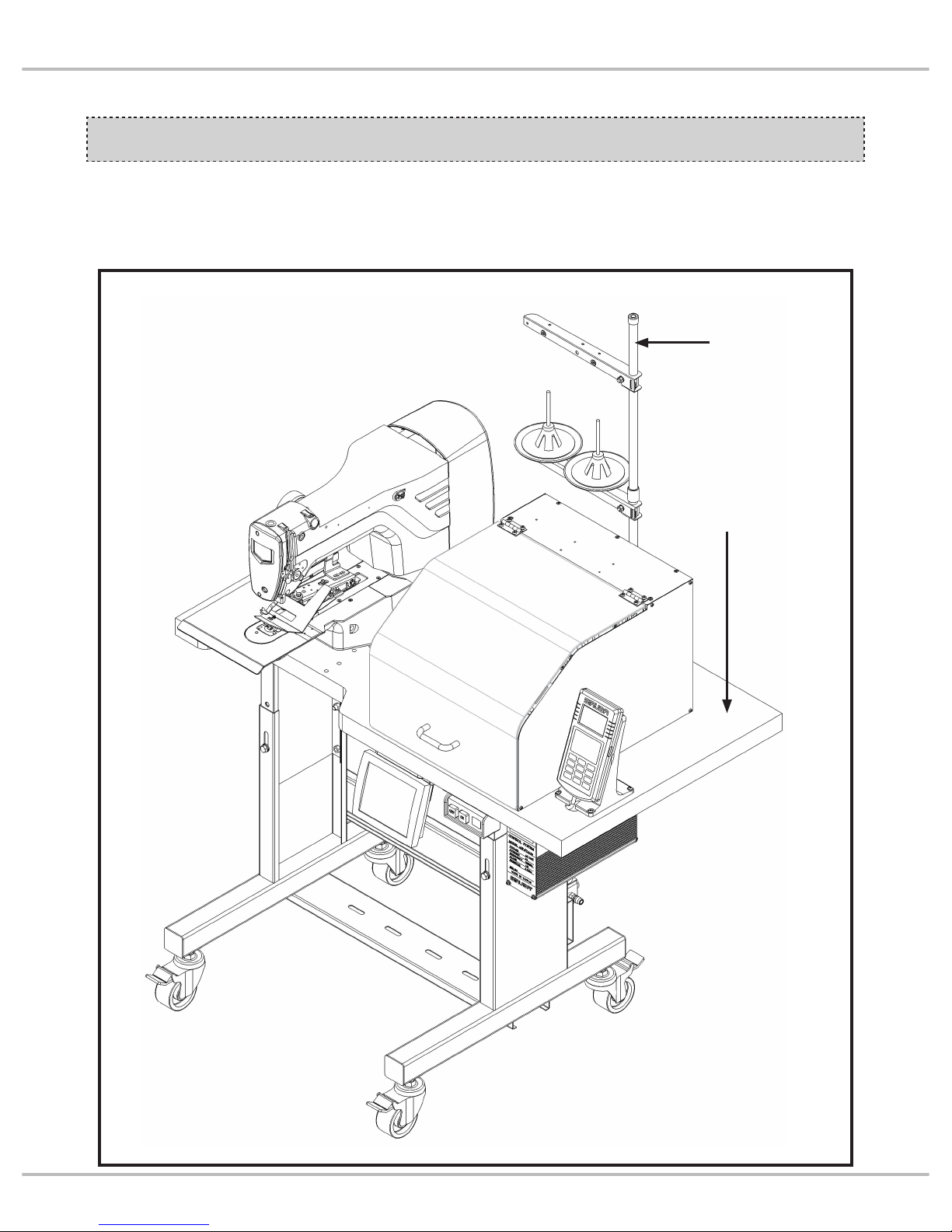
桌板①上,鎖付線架②。
( 線架組裝組請參照 LKS-1903AN 使用說明書 。)
Install thread rack ② on the table ①.
(Ref LKS-1903AN user manual.)
安裝
INSTALLATION
②
①
線架
Thread rack
P2
Introduction
Page 8
1. 電源電壓
A. 單相 AC200~240V 50/60Hz ±10%。
B. 接地線一定要接地。
2. 氣壓
A. 使用 0.5 Mpa(5kg/c㎡ )。
3. 供油
A. 縫紉機頭部
請參照 LKS-1903AN 使用說明書。
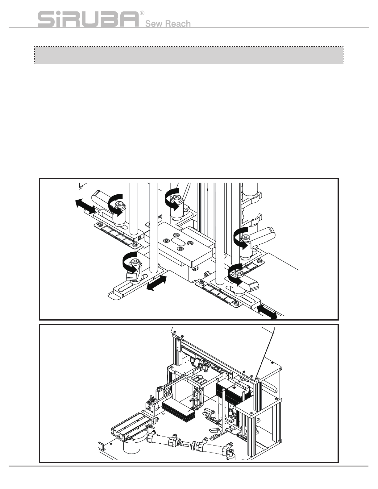
4. 設定紙卡尺寸及補料
鬆開快速把手①後調整滑塊②至紙卡規格對
應尺寸,再將料卡放置於載料平台。
1.Voltage
A. Single Phase AC200~240V 50/60Hz ±10%
B. Ground wire must connect.
2.Air pressure
A. Use 0.5 Mpa(5kg/c㎡ )。
3.Feed oil
A. Machine head
Ref LKS-1903AN user manual.
4. Set label dimension and fill the material
After loosing quick spancer
① , adjust sliding
block ② to satisfy label dimension and then
put label material on material platform.
運轉準備
OPERATION PREPARATION
P3
Page 9
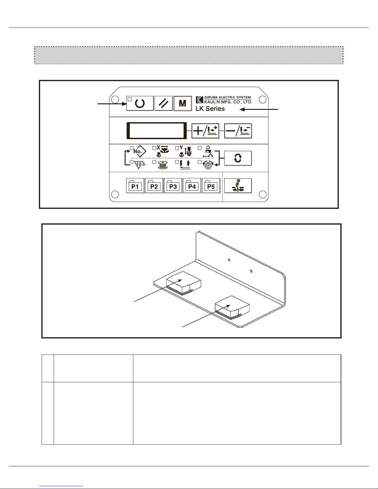
1. 操作面板 1. Operation panel
操作面板與啟動開關
OPERATION SWITCH
準備鍵
Ready button
SIRUBA
LKS-1903AN
操作面板
Operation panel
P4
Introduction
啟動開關
Activation switch
壓腳開關
Switch for presser foot
1
直接啟動車縫模式
Directly sewing mode
踩踏啟動開關時,壓腳自動下壓就直接車縫
When activation switch, lowering presser foot automatically, then
directly start sewing
2
兩段式車縫模式
2-step sewing mode
單踩壓腳開關時,可使壓腳下壓或抬升用於車縫對位,壓腳必須處
於下壓狀態,踩踏啟動開關才有作用,壓腳未下壓則無法啟動車縫
動作
We could merely tread switch for presser foot to lower or to raise
presser foot to align sewing position. Users should lower presser
foot and then activation switch will work. If
not, users could not
start sewing.
啟動車縫有兩種模式: Two modes to enable sewing:
※ 模式選擇請參閱人機介面使用說明 ※Please refer to instruction book of human
machine interface for mode selection
2. 腳踏開關 2. Knee pedal switches
Page 10
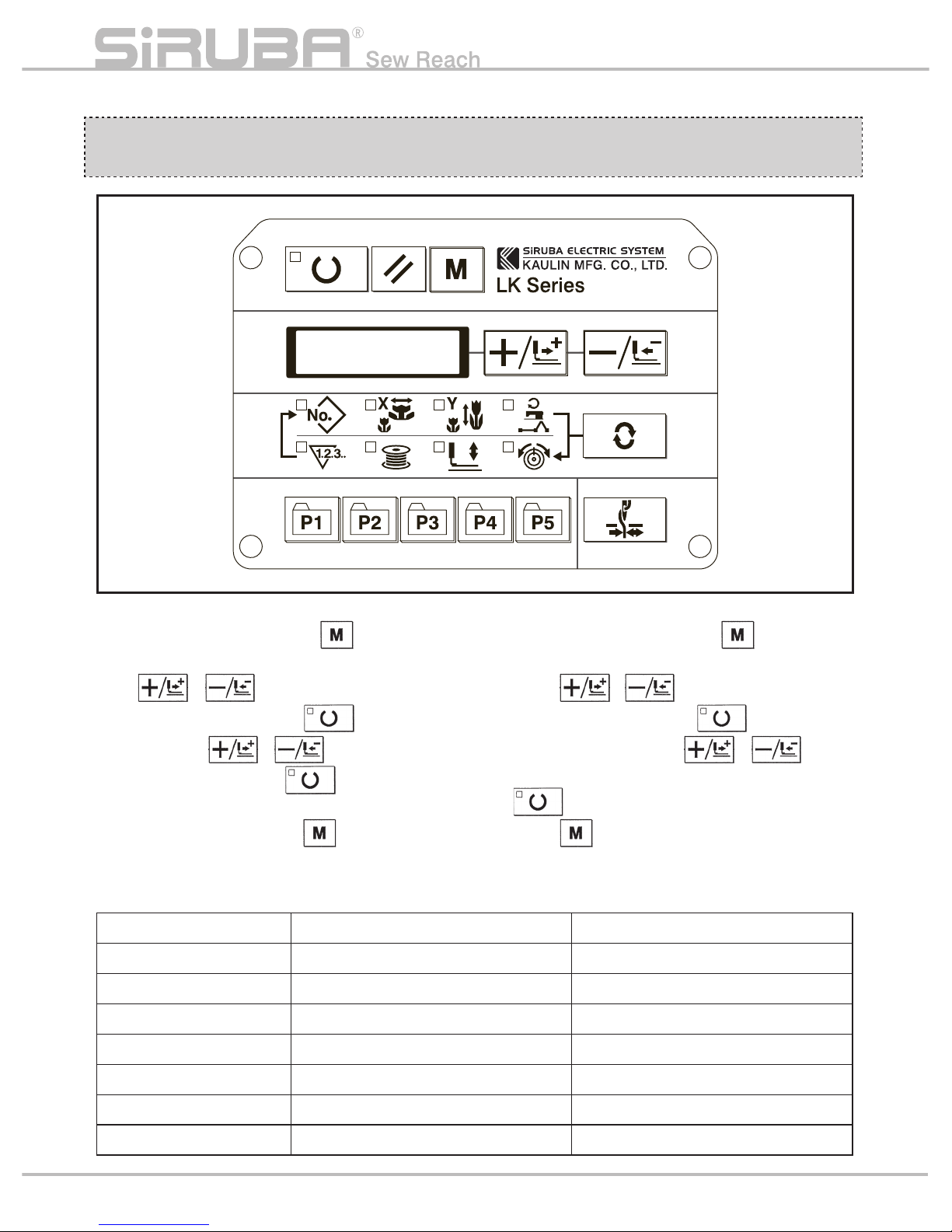
車頭參數設定
MACHINE HEAD
CONFIGURATION SETTING
1. 按下 電源 ON 開關,按 住 鍵約 6 秒進
入設定模式。
2. 按
、 鍵選擇參數。
3. 找到要變更的參 數,按
鍵,進入修
改模式,按
、 鍵來變更內容,
更改完 後,再 按一次
鍵跳出修 改模
式。
4. 所有參數都修改完後按
鍵跳出設定模
式。
5. 修改的參數內容如下
1.Press power on switch hold
about 6
seconds to enter setting mode.
2.Press
、 button to select figures.
3.Select the figures. Press
button enter
adjusting mode. Press
、 to
change content. After adjustment, press
to exit adjusting mode setting value.
4.Press
button to exit setting mode.
5.Refer below for configuration figurces.
順序 Sequence 參數編號 Configuration No. 設定值 Setting value
1 241 9
2 19 2
3 20 1
4 24 0
5 37 1
6 51 1
7 62 1
P5
Page 11
紙卡安裝與對位
LABEL INSTALLATION AND ALIGNMENT
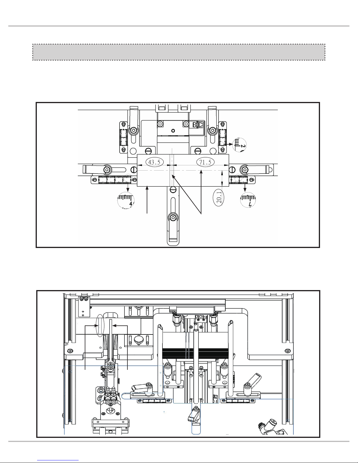
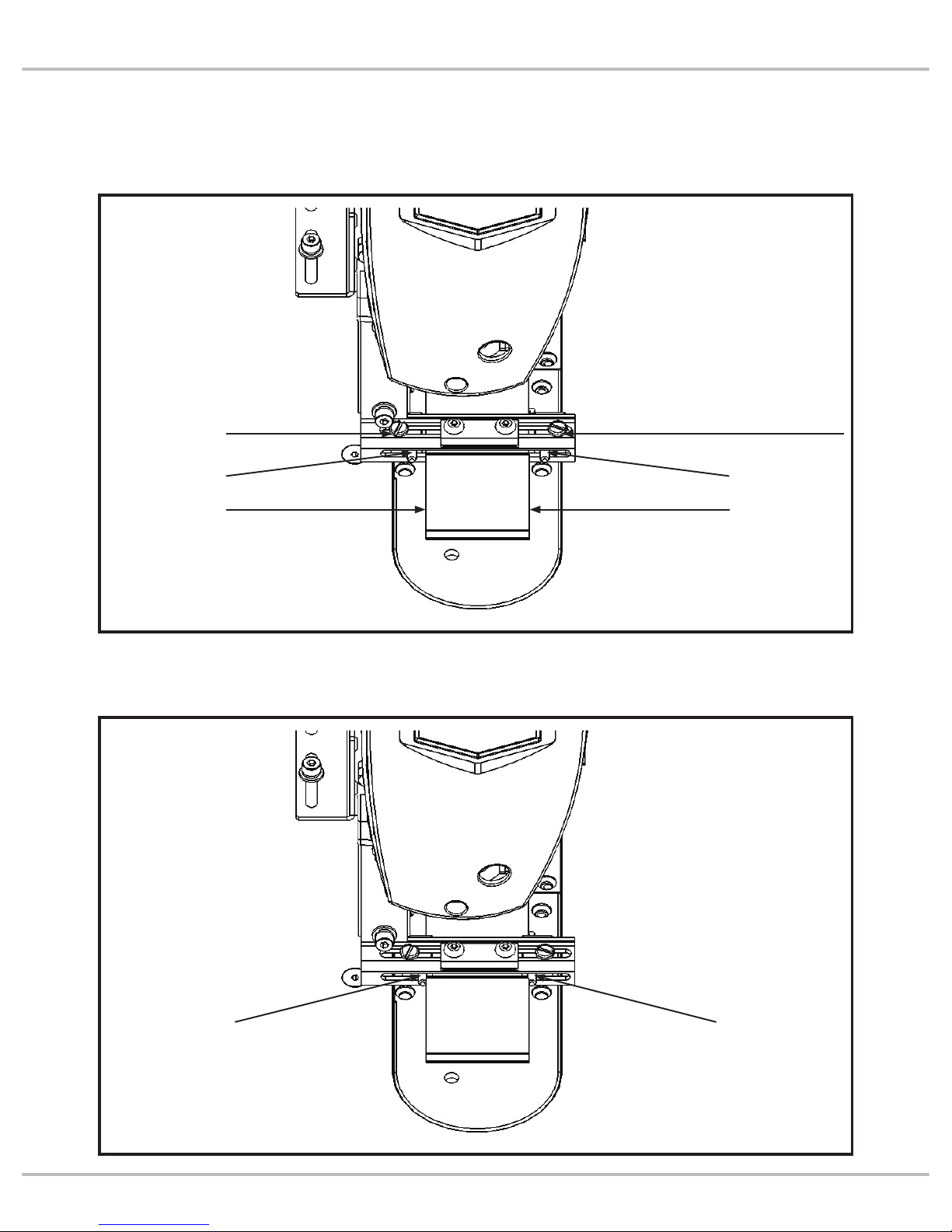
1. 紙卡尺寸變更時
依紙卡摺痕中心至左及右邊的長度來調整
滑塊對應的刻度,寬度亦是如此。
2. 紙卡摺痕偏移調整
若紙卡摺痕偏離夾具位置時,需微量調整紙
卡安裝位置以符合夾持位置。
1.When label dimension changes
According to label crease center, adjust
length between left border and right border
and then adjust width by the same way.
2.Adjust the deviation of label crease
If label crease deviates from the clamp
position, fine tune the installation posit
ion of
label to fit clamp position.
P6
Introduction
紙卡
Label
摺痕
Crease
紙卡摺痕中心
Label crease center
夾具
Clamp
Page 12
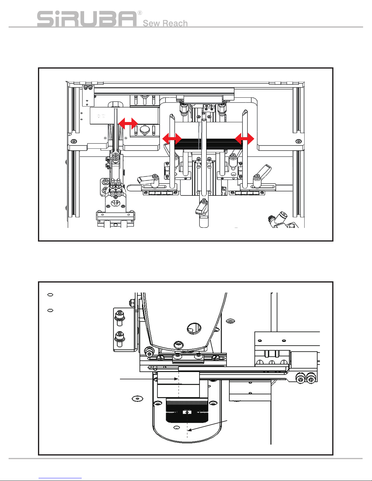
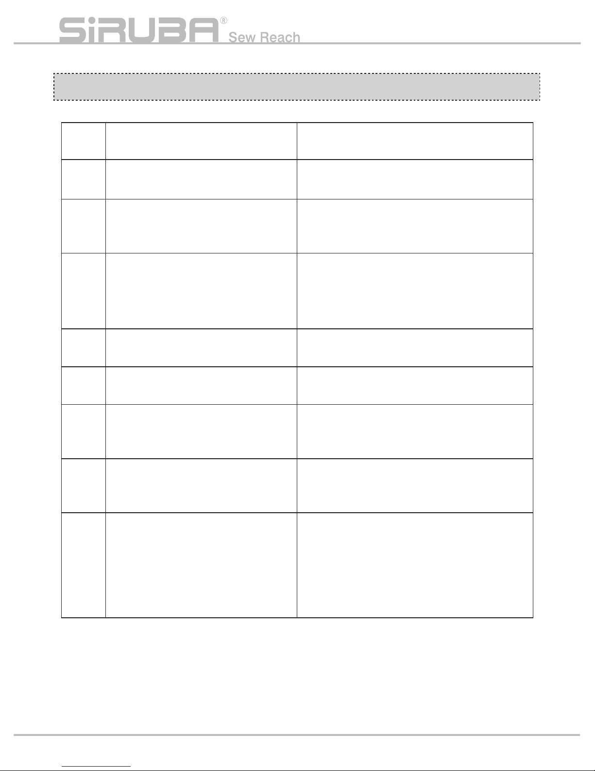
微調紙卡長度位置即可將摺痕偏移至夾具位
置。
Fine-tune label length position to move the
crease deviation to the clamp position
3. 縫線位置調整
紙卡中心偏左或偏右時,將造成縫線不在卡
片正中心位置上。
3. Adjust sewing position
When label deviate left or right from center,
sewing line will not be in the middle of label.
P7
卡片中心線
Label center
縫紉中心
Sewing center
Page 13
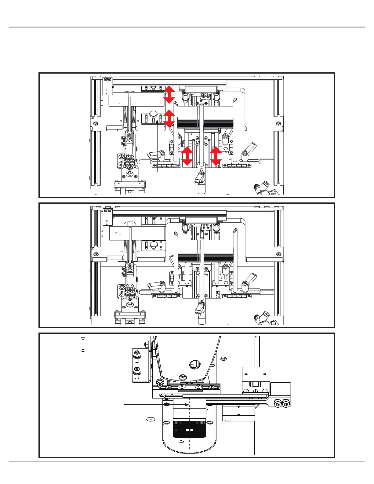
微調卡片寬度位置與限位塊即可改變縫線偏
左或偏右的問題。
Fine-tune label width position and limiting
block to solve the problem that sewing line
deviates left or right.
P8
Introduction
中心線對準
Align center line
限位塊
Limiting block
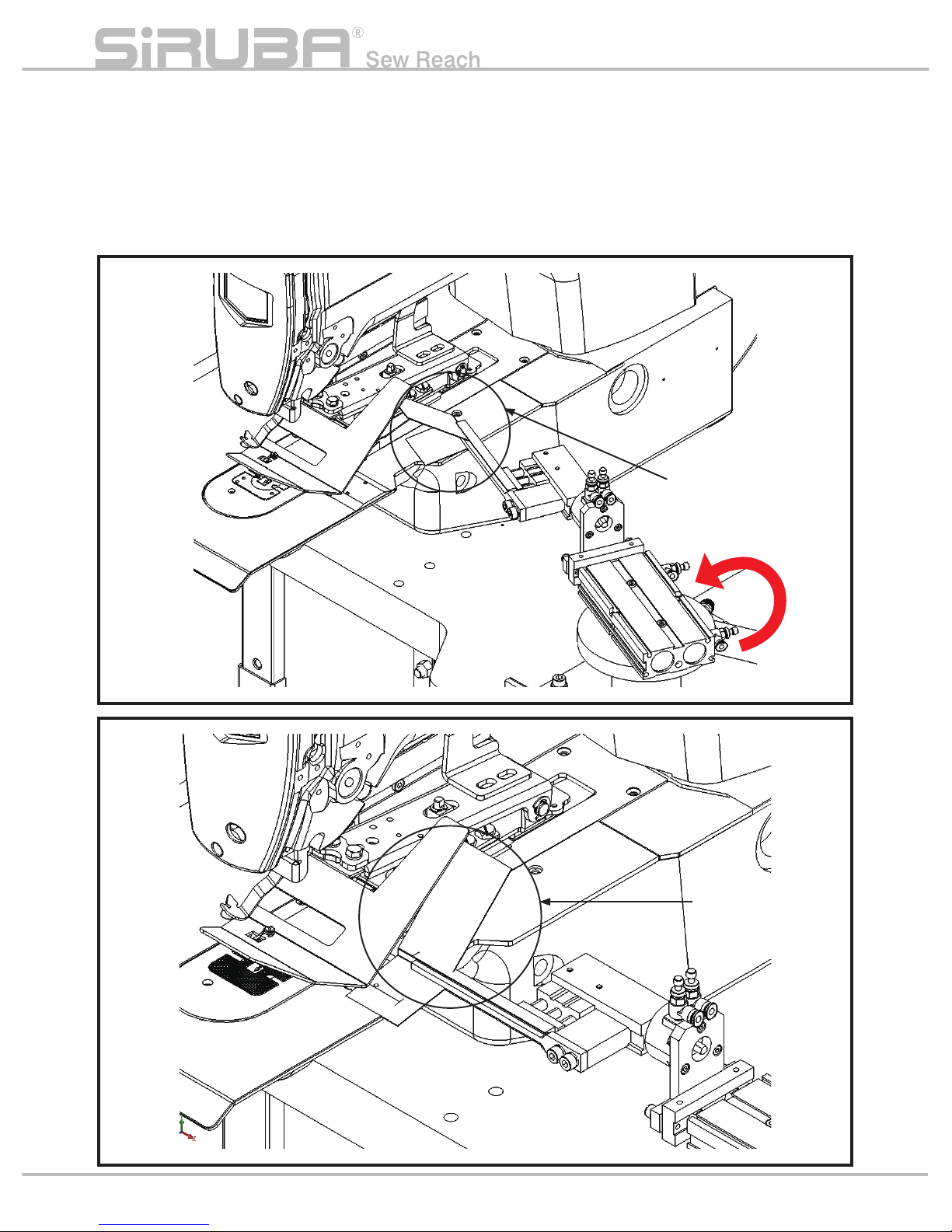
Page 14
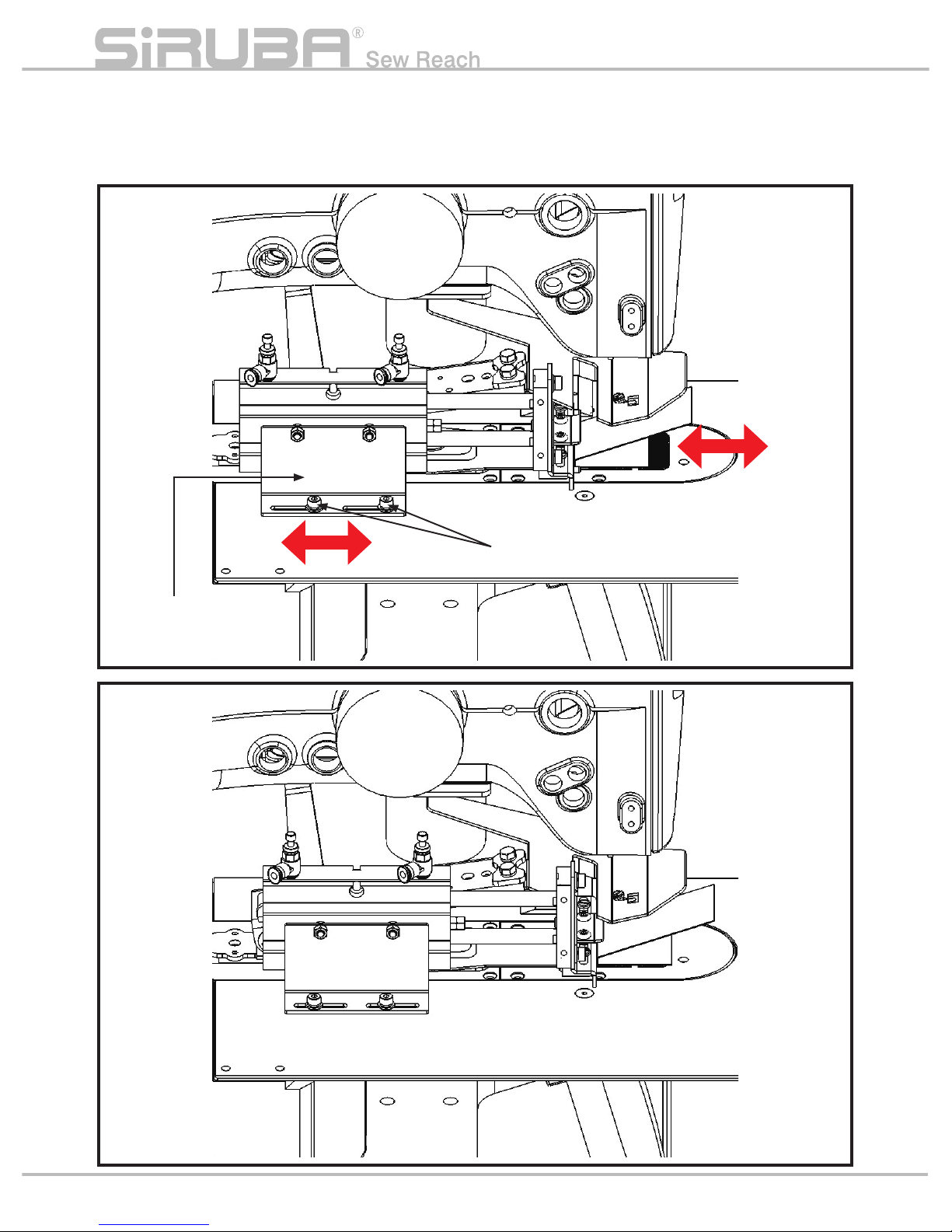
調整擋邊氣缸固定座可決定紙卡縫線前後的
位置。
Adjust guide block cylinder seat to set label
sewing line position.
P9
擋邊氣缸固定座
Guide block cylinder seat
螺絲鬆開後調整
Adjust after loosing screws
Page 15
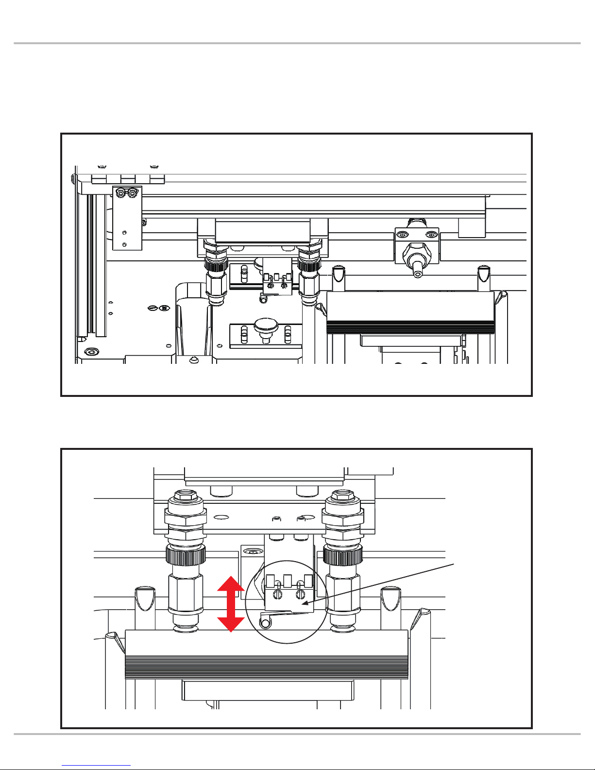
限位銷可限制紙卡左右些許的偏差範圍,當
卡片寬度變更時需調整至紙卡邊界。
Limited pin could limit the deviation of the
label. When label width changes, limited pin
needs to adjust to the label boundary.
限位銷與紙卡邊界需留間隙約 0.5 ~ 1mm,
如此紙卡才不會被撞歪。
Need to keep 0.5~1 mm space for limited pin
and label. Then label will not crash.
P10
Introduction
螺絲鬆開可調整位置
Loose screw to adjust
the position
螺絲鬆開可調整位置
Loose screw to adjust the position
限位銷
Limited pin
保留間隙
Keep space
限位銷
Limited pin
保留間隙
Keep space
紙卡邊界
Label boundary
紙卡邊界
Label boundary
Page 16
錯誤代碼 ERROR CODE
代碼
Code
說明
Description
備註
Memo
E01
通訊異常
Network error
見 4. 故障排除 章節
Ref. by paragraph 4.Trouble shooting
E02
缺料顯示
Show lack of material
待載料平台下降,進行補料後,按下重置鍵
Lower material platform, fill material and press
reset button
E11
運料氣缸未確實處於
準備點 / 原點位置
Cylinder for material transmission
does not stay in standby/original
position well
1 號氣缸 / 準備點微動開關 / 原點磁簧開關異常
No. 1 cylinder/standby point micro switch or
original point re
ed switch error
E12
前伸氣缸未確實縮回
Forward cylinder does not retract well
2 號氣缸 / 磁簧開關異常
No. 2 cylinder/reed switch error
E14
塑形氣缸未確實下降
Forming cylinder does not lower well
4 號氣缸 / 磁簧開關異常
No. 4 cylinder/reed switch error
E16
夾料臂未確實到待命令位置
Clamp does not arrive standby point
well
6 號氣缸 / 磁簧開關異常
No. 6 cylinder/reed switch error
E18
擋邊氣缸未確實退回
Guide block cylinder does not return
well
8 號氣缸 / 磁簧開關異常
No. 8 cylinder/reed swi
tch error
-
若於運料時,運料失敗,導致成型區
感應器未判讀有料,夾爪不會執行前
伸動作
If transmitting material is not well,
sensor on forming part does not detect
material. Clamp will not forward and
catch material
按下 重置鍵 再次進行運料動作
Press reset and feed material again
P11
Page 17
異常排除
TROUBLE SHOOTING
現象
Description
原因
Reason
對策
Solution
參考頁數
Ref. page
摺痕未對夾具中心
Crease is not in the clamp
middle
1. 紙卡安裝位置偏移。
2. 夾具機構位置錯誤。
1.Label position
deviates
2.Clamp position error
1. 微調料槽長度滑塊位
置。
2. 調整氣缸束環位置。
1.Fine tune length
sliding block position
of material platform
2.Adjust the position of
cylinder limiting ring
P.00~P.00
P.00
縫線未在紙卡正中心
Sewing line is not on the label
middle.
1. 紙卡安裝位置偏移
1.Label position
deviates
微調料槽寬度滑塊位
置及限位塊。
Fine tune position of
width sliding block
and limiting block
P.00~P.00
縫線未在指定位置
Sewing line is not on assigned
location
1. 擋邊氣缸位置錯誤
1.Wrong position of
guide block cylinder
微調擋邊氣缸固定座的
鎖固位置。
Fine tune fixed position
of guide block cylinder
seat
P.00
夾槽無法開啟
Unable to open clamp
slotlocation
1. 疊料造成
1.Materials overlap.
吸盤分料時,調整吹嘴
角度與風量使疊料分
離。
When suction cup
catches material,
adjust the angle of air
nozzle and the strength
of air to separate
material stack.
P.00
P12
Introduction
實際位置
Actual location
實際位置
Actual location
預定位置
Assigned
location
預定位置
Assigned
location
Page 18
現象
Description
原因
Reason
對策
Solution
參考頁數
Ref. page
成形角度不足
Forming angle is not enough 1. 夾槽選用錯誤。
1. Select wrong clamp
slot
更換適用該紙卡摺痕
寬度的夾槽。
Replace clamp slot
which is suitable for
label crease width.
P.00~P.00
吸盤取料失敗
Failure to catch material by
suction cup
1. 載料平台上升停止
位置過低。
1.Material platform
raises not enough.
微調入料檢知位置。
Fine-tune filling
detection position.
P.00
夾具撞擊夾料區紙卡
Clamp crashes label on forming
part
1. 料卡不平整拱起而
被進
入的夾棒撞歪。
1.Material label is not
flat and arch so it is
crashed by clamping
rod when rod is
entering
料卡拱起程度不可超
過 3mm,需人工整
平。
Material label can not
arch more than 3 mm
or need to smoothen
it by users.
P.00
P13
Page 19

1. 紙卡疊料
吸盤吸附紙卡兩張以上時,將造成夾具無法
開夾而異常,此時可以調整吹氣嘴的角度與
吹氣量大小來進行疊料排除。(註: 紙卡若
因印刷油墨沾黏則需人工排除)
1. Labels overlap
When suction cup catches more than 2 labels,
clamp will not open and error. In this situation,
we can adjust the angle of air nozzle and the
strength of air blow to remove material stack
(note: users will need to remove by hand if
labels stick together by ink or else)
旋轉螺桿可調整吹氣量大小
Able to adjust blowing strength
by rotatory screw rod
需使用 3mm 六角板手伸入氣孔調整吹氣角度
Need to use 3 m m hex wrench to enter air
inlet to adjust the angle of blowing air
氣嘴調整方式
Air nozzle adjustment
氣嘴
Air nozzle
P14
Introduction
Page 20
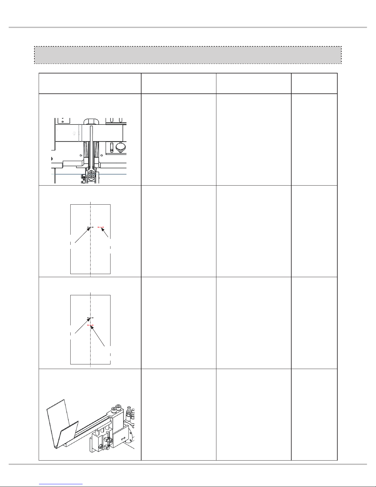
2. 成型角度不足
夾具有對應摺痕5mm或6mm寬的夾槽,
當成型角度不足時,會發生進料失敗的情形,
此時需更換正確的夾槽才能順利成形。
2.Incorrect forming angle
Clamp need to match 5mm or 6mm width
clamp slot. When the forming angle is not
enough, feeding process will be error. In such
situation, we need to replace correct clamp
slot to form it correct.
P15
夾角過大
Too large angle
進料失敗
Failure to
feed material
Page 21

夾槽選用錯誤時將產生成形角度不足的問題
If choosing wrong clamp slot, it will result in
the problem of not enough forming angle.
夾槽更換方式
Exchange of clamp slot
P16
Introduction
摺痕 5mm 寬的紙卡
5
mm
width Label
crease
摺痕 6mm 寬的紙卡
6
mm
width Label
crease
5mm 寬的夾槽
5
mm
width clamp slot
6mm 寬的夾槽
6
mm
width clamp slot
夾棒
Clamp rod
鬆開螺絲將夾棒拆下後,可拆除夾槽
內鎖固螺絲再進行更換夾槽作業
After loosing screws and remove
clamp rod, we could remove locking
screws in clamp slot and then start
to change clamp slot
夾槽
Clamp slot
Page 22

3. 機構位置錯誤
夾 具 歪 斜 可 鬆 開 汽 缸 束 環 的 位 置 來 進 行 微
調。
3. Incorrect mechanism position
If clamp skews, we can loose cylinder limiting
ring for fine tuning the position.
限位束環是鎖在氣缸軸上,鬆開螺絲後微調
位置再鎖固即可改變夾具歪斜角度。
Limiting ring is locked on the cylinder shaft.
Loose, fine-tune position and then lock the
screw to adjust the clamp skew angle.
P17
夾具歪斜
Clamp skews
限位束環
Limiting ring
限位束環
Limiting ring
Page 23
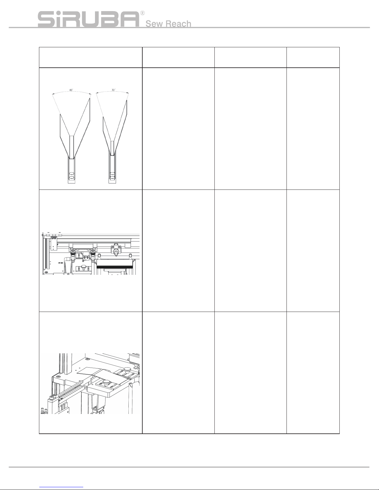
4. 吸盤取料失敗
台移載時未將料卡吸住則為取料失敗
4. Failure for suction cup to catch material
When suction cup platform moves to next
step but does not catch material label well,
suction cup fails to catch material.
調整入料檢知位置可決定載料平台的上升高
度。
To adjust filling detection position could
control the raise height of material platform.
P18
Introduction
鬆開螺絲後可
調整檢知位置
After loosing
screws, we
could adjust
detection
position
Page 24

真空吸氣量亦是取料因素之一,可單獨調整
氣壓調速閥控制吸力大小。若發現過濾器已
髒汙嚴重時請進行更換,未更換則吸力會因
阻塞逐漸變弱。
Vacuum suction strength is also a factor to
catch material label. We can only adjust flow
control valve to adjust suction strength. If
users find air filters seriously polluted, please
replace it, or suction strength will become
lesser because of blocks.
P19
過濾器
Filter
真空產生器
Vacuum generator
氣壓調速閥
Adjustable valve of air
pressure
Page 25

動作模式
MODE SELECT
(1)單動模式 ( 1 ) Single-step mode
手動狀態 Manual mode
選擇手動模式 OK,車頭 READY,機構回
原點
Select manual mode -> OK, machine
head READY, machine back to original
point
載料平台下降至下極限點,放入料卡
Lower material platform to lower limit and
fill material labels
吸盤平台 ON -移動向後
Suction cup platform ON - move forward
載料平台上升至吸料高度
Raise material platform to the level to catch
material
吸盤 ON -吸附
吹嘴 ON
載料平台下降至待命點
Suction cup ON - attach
Blow ON
Lower material platform until ready
吸盤平台 ON -移動向前
Suction cup platform ON - move forward
吸盤 OFF -紙卡落下
吹嘴 OFF
Suction cup OFF - label fall down
Air nozzle OFF
吸盤平台 OFF -移動向後
Suction cup platform OFF - move
backward
前伸氣缸 ON -進入夾料區
Forward cylinder ON - enter material
region
夾具氣缸 ON -夾持
Clamp cylinder ON - clamp
整形氣缸 ON -上升整形
Forming cylinder ON - raise to form
前伸氣缸 OFF -後退
Forward cylinder OFF - backward
整形氣缸 OFF -下降
Forming cylinder OFF - lower
待轉氣缸 ON -待轉區
Standby cylinder ON - standby region
旋轉缸 ON -旋轉
Rotatory cylinder ON - rotate
進料氣缸 ON -進料
Feeding cylinder ON - feed material
前伸氣缸 ON -進入車縫區
Forward cylinder ON - enter sewing
region
壓腳下壓
Lower presser foot
夾具氣缸 OFF -開夾
Clamp cylinder OFF - open clamp
前伸氣缸 OFF -後退
Forward cylinder OFF - backward
擋邊氣缸 ON -推至縫紉區
Guide block cylinder ON - move to
sewing region
壓腳抬起
Raise presser foot
壓腳下壓,車縫開始-結束
Lower presser foot, sewing start-finish
P20
Introduction
Page 26

(2)自動模式 (2)Automatic mode
手動狀態 Manual mode
自動狀態 Automatic mode
吸盤平台 ON -移動向後
Suction cup platform ON - move forward
載料平台上升至吸料高度
Raise material platform to the level to catch
material
檢查夾料區訊號
Check the signal
from forming region
吸盤 ON -吸附
吹嘴 ON
載料平台下降至待命點
Suction cup ON - attach,
Blow ON (2 secs),
Llower material platform to standby point
吸盤平台 ON -移動向前
Suction cup platform ON - move forward
吸盤 OFF -紙卡落下
Suction cup OFF - label fall down
吸盤平台 OFF -移動向後
Suction cup platform OFF - move
backward
檢查夾料區訊號
Check the signal
from forming region
前伸氣缸 ON -進入夾料區
Forward cylinder ON - enter material
region
夾具氣缸 ON -夾持
Clamp cylinder ON - clamp
整形氣缸 ON -上升整形
Forming cylinder ON - raise to form
前伸氣缸 OFF -後退
整形氣缸 OFF -下降
Forward cylinder OFF - backward
Forming cylinder OFF - lower
開機第一次 FEED
First FEED after
turning on
進料氣缸 OFF
待轉氣缸 OFF
旋轉缸 OFF
Feed cylinder OFF
待轉氣缸 OFF
Rotatory cylinder OFF
選擇手動模式 OK,車頭 READY,機構回原點
Select manual mode -> OK, machine head READY,
machine back to original point
載料平台下降至下極限點,放入料卡
Lower material platform to lower limit and fill material labels
待轉氣缸 ON -待轉區
Standby cylinder ON - standby
region
旋轉缸 ON -旋轉
Rotatory cylinder ON - rotate
檢查車縫結束訊號
Check sewing
finish signal
進料氣缸 ON -進料
Feeding cylinder ON - feed
material
前伸氣缸 ON -進入車縫區
Forward cylinder ON - enter
sewing region
壓腳下壓
Lower presser foot
夾具氣缸 OFF -開夾
Clamp cylinder OFF - open clamp
前伸氣缸 OFF -後退
Forward cylinder OFF - backward
擋邊氣缸 ON -推至縫紉區
Guide block cylinder ON - move
to sewing region
壓腳抬起
Raise presser foot
壓腳下壓,車縫開始
Lower presser foot and start
sewing
車縫結束
Finish sewing
P21
Page 27

(3)單縫模式(補縫模式)
開啟電源後,在單動模式下按下人機介面數
字鍵8即進入單縫模式,此時自動送料機構
停止動作。主要用於人工摺紙卡再進行車縫
或補縫用。
(4)單捲線模式
此模式下可單獨捲線
注意!!啟動此模式前請將車針拆下避免撞
斷車針
依照下列順序進行。
A. 將 " 電源開關① " 切至OFF。
B. 將 " 電源開關① " 切至O N。
D. 按下 " 準備鍵② " 變成O N。
E. 按下 " 準備鍵② " 變成OFF。
G. 按下 " 運轉鍵③ ",使其燈號在 " 捲線圖案
" 上亮起。
H. 按下 " 準備鍵② " 變成O N。
I. 按下 " 起動鍵④ " 即可運轉。
J. 捲完線,按下 " 起動鍵④ " 即可停止。
(3)Only sewing mode (re-sew mode)
After turning on the power, press number "8"
on the panel in s
tep mode to enter only sewing
mode. Then, automatic feeder stop working.
This mode is mainly designed for users to fold
label by hand and then to sew or to re-sew it.
(4)Only winding mode
We could only wind in this mode.
Notice !! Please remove sewing needle to
prevent crushing the needle before activating
this mode.
Follow below sequences:
A. Turn OFF "Power switch ① ".
B. Turn ON "Power switch ① ".
D. Press "Ready ② " to become ON.
E. Press "Ready ② " to become OFF.
G. Press "Operarion ③ " to turn on "Winding
symbol" light.
H. Press "Ready ② " to become ON.
I. Press "Activation switch ④ " to run.
J. After winding, press "Activation switch ④ " to
stop.
P22
Introduction
捲線圖案 Winding symbol
①
②
③
④
Page 28
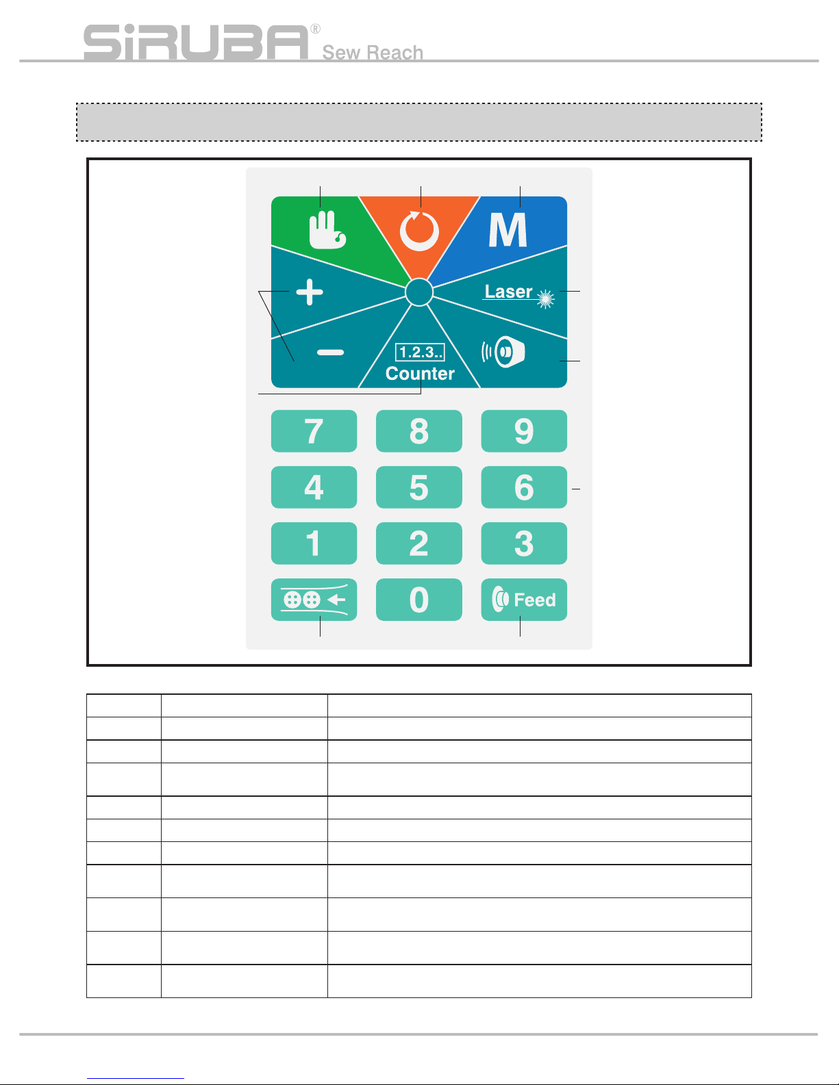
按鍵說明 BUTTON INSTRUCTIONS
代號 Code 名稱 Description 備註 Memo
1 確認 ( 準備 ) Enter
2 重置 Reset
3 參數 Parameter
在主頁面時按下可進入 A 參數頁面。
Press this key to enter "A" parameter page under main menu.
4 備用 Spare 無使用。No function
5 備用 Spare 無使用。No function
6 備用 Spare 無使用。No function
7 選擇 ( 調整 ) Select
進入參數調整與馬達測試時使用
Use for parameter adjustment or motor test
8 數字鍵 Digit Key
氣缸測試模式時使用
Use for test mode of an air cylinder
9 送料鍵 Feed Material
送紙卡至待車縫區
Send label to sewing region
10 補料鍵 Fill Material
自動模式時,讓載料平台下降,進行補料動作
In automatic mode, lower material platform and then fill materials
P23
① ② ③
④
⑤
⑥
⑦
⑧
⑨⑩
Page 29

操作說明 OPERATION INSTRUCTION
Auto Run 操作說明 < 單踏板 > Auto Run operation instruction<single pedal>
按確認鍵進入模式
Press enter button
to enter the mode
主畫面顯示
Auto 模式
Home screen
shows Auto mode
按送料鍵進行送料動作 ( 第一步
動作須先送一紙卡至待車縫區 )
Press this button to feed material
(first step is to send one label to
sewing region )
進入 Auto Run
模式
Enter Auto Run
mode
踩車縫踏板 (L)
進行車縫與送料動作
Tread on activation pedal (L)
to process sewing
按補料鍵進行補
料動作
Press this button
to fill material
按送料鍵進行送料動作
Press this button to feed material
補料完成後按下重
置鍵
After
filling material,
press reset button
按確認鍵 離開 Auto Run 模式
Press enter button to leave Auto
Run mode
經人工判斷發現夾到兩張紙卡時,先按一次重置鍵,
手動將紙卡取出,再按一次重置鍵,進行再次夾料
動作
If users find more than two labels on the clamp,
press reset button first and then take labels out.
Press reset button again and then let machine
clamps material again
夾料臂於待命令
位置 , 等待命令
Clamp stays in
original and wait
for order
Au to
Mode
:
STAR T
Fu nction
Auto Run
P24
Introduction
Page 30

Auto Run 操作說明 < 雙踏板 > Auto Run operation instruction <2-step pedals>
踩壓腳踏板 (R) 將壓腳下壓
Tread on this pedal (R)
to lower presser foot
踩車縫踏板 (L) 進行車縫與送料動作
Tread on activation pedal (L)
to process sewing and feeding
按補料鍵進行補料動作
Press this button to fill
material
按送料鍵進行送料動作
Press this button to send material
(must raise presser foot in advance)
補料完成後按下重置鍵
After filling material,
press reset button
按確認鍵 離開 Auto Run 模式
Press enter button to leave Auto Run mode
經人工判斷發現夾到兩張紙卡時,先按一次 重置鍵,手
動將
紙卡取出,再按一次 重置鍵,進行再次夾料動作
If users find more than two labels on the clamp, press reset
button first and then take labels out. Press reset button again
and then let machine clamps material again
夾料臂於待
命令位置 , 等
待命令
Clamp stays
in original
and wait for
order
按確認鍵進入模式
Press enter button
to enter the mode
主畫面顯示
Auto 模式
Home screen
shows Auto mode
按送料鍵進行送料動作 ( 第一步
動作須先送一紙卡至待車縫區 )
Press this button to feed material
(first step is to send one label to
sewing region )
進入 Auto Run
模式
Enter Auto Run
mode
Au to
Mode
:
STAR T
Fu nction
Auto Run
P25
Page 31

Manual 模式 < 單踏板 > Manual mode <One pedal>
Manual 模式 < 雙踏板 > Manual mode <2-step pedals>
進入 Manual 模式
Enter Manual mode
進入 Manual 模式
Enter Manual mode
踩車縫踏板 (L) 執行車縫動作
Tread on activation pedal (L)
to process sewing
踩壓腳踏板 (R) 將壓腳下壓
Tread pedal for presser foot (R) to lower presser foot
踩車縫踏板 (L) 執行車縫動作
Tread activation pedal (L) to process sewing
按 選擇鍵 + 進行下一步動作
Press select button “+" to process next step
按數字鍵 8 將擋邊伸出 / 退回
Press number “8" to stretch guide block out/back
按確認鍵離開 Manual 模式
Press enter to leave
Manual mode
Manual
Manual
按確認鍵進入模式
Press enter button
to enter the mode
按確認鍵進入模式
Press enter button
to enter the mode
主畫面顯示 Auto 模式
Home screen shows Auto mode
主畫面顯示 Auto 模式
Home screen shows Auto mode
Au to
Mode
:
STAR T
Fu nction
Au to
Mode
:
STAR T
Fu nction
按 選擇鍵 + 進行下一步動作
Press select button “+" to process next step
按數字鍵 8 將擋邊伸出 / 退回
Press number “8" to stretch guide block out/back
按確認鍵離開 Manual 模式
Press enter to leave Manual mode
P26
Introduction
Page 32

模式選擇方式 Mode selection
按確認鍵進入
Press enter button
to enter system
主畫面顯示當前模式
Home screen shows
present mode
按選擇鍵選擇模式
Press select button
to select mode
Au to
Mode
:
STAR T
Fu nction
Mode
:
STAR T
Fu nction
Manual
M
Au to
Mode
:
STAR T
Fu nction
參數說明 PARAMETER INSTRUCTION
Item
參數編號
Code
參數名稱 Description 備註 Memo
1 A01
電磁閥 / 壓腳測試 Solenoid valve / presser foot test
0~9 , 補料鍵
0~9 , button to fill material
電磁閥
編號
Solenoid
valve
No.
1 運料電磁閥 Transmission solenoid valve
2 前伸電磁閥 Forward solenoid valve
3 夾爪電磁閥 Clamp solenoid valve
4 塑型電磁閥 Forming solenoid valve
5 翻轉電磁閥 Rotation solenoid valve
6 定位電磁閥 Position solenoid valve
7 到位電磁閥 Arrival solenoid valve
8 擋邊電磁閥 Guide block solenoid valve
9 壓腳 Pre
sser foot
0 吸嘴電磁閥 air nozzle solenoid valve
補料鍵
Fill material
吹氣電磁閥 Blowing solenoid valve
2 A02 SENSOR / 訊號 測試 SENSOR / signal test IN1~IN9 , INA~INC
SENSOR
編號
SENSOR
No.
IN1 前伸氣缸磁簧開關 Forward cylinder reed switch
IN2 塑型氣缸磁簧開關 Forming cylinder reed switch
IN3 定位氣缸磁簧開關 Position cylinder reed switch
IN4
擋邊氣缸磁簧開關 Guide block cylinder reed switch
IN5 車縫踏板訊號 Sewing activation pedal signal
IN6
準備點位置微動開關
Micro switch on stan
dby point of suction cup
IN7 成型區感應器 Sensor on forming part
IN8
原點位置磁簧開關
Reed switch on original point of suction cup
IN9 上極限開關 Upper limit switch
INA 下極限開關 Lower limit switch
INB 有料判別開關 Storage material detect sensor
INC 壓腳踏板訊號 Presser foot pedal signal
3 A03 入料動作測試 Filling material test
4 A04 步進馬達動作測試 Stepping motor action test
5 A05
單 / 雙 踏板動作方式選擇
Select one/two-step pedals
1 : 單踏板方式 .2 : 雙踏板方式
1:one pedal/ 2:2-step pedals
7 版本顯示 Version display
P27
Page 33

A01 各電磁閥測試 A01 test each solenoid valve
進入後以下列選擇數字鍵 / 補料鍵測試 After entering parameter menu, press following
numeric key/ filling button to test
附註 :
●
運料氣缸需馬達於下極限與前伸氣缸於縮回狀態才
能做動
●
前伸氣缸需運料氣缸於原點位置才能做動
●
翻轉氣缸需前伸氣缸於縮回狀態與夾料臂於待命令
位置點才能做動
●
定位氣缸需前伸氣缸於縮回狀態與翻轉氣缸未翻轉
狀態下才能做動
●
到位氣缸需前伸氣缸於縮回狀態與夾料臂於待命令
位置點才能做動
●
壓腳動作需 JUKI 車頭為 Ready 狀態下才能做動
Memo:
●
Transmission cylinder only works when motor is on
lower limit and forward cylinder moves back
●
Forward cylinder only works when transmission
cylinder on the original point
●
Rotation cylinder only works when forward cylinder
moves back and clamp is at standby point
●
Position cylinder only works when forward cylinder
moves back and rotation cylinder does not rotate.
●
Arrival cylinder only works when forward cylinder
moves back and clamp is at standby point
●
Presser foot only works when JUKI machine head
is on ready status
A 參數 - 需在主頁面按才有動作 A parameter - only activate on home screen
數字鍵
Number key
電磁閥
Valve
說明
Description
1
電磁閥 1
Valve 1
運料電磁閥
Transmission solenoid valve
2
電磁閥 2
Valve 2
前伸電磁閥
Forward solenoid valve
3
電磁閥 3
Valve 3
夾爪電磁閥
Clamp solenoid valve
4
電磁閥 4
Valve 4
塑型電磁閥
Forming solenoid valve
5
電磁閥 5
Valve 5
翻轉電磁閥
Rotation solenoid valve
6
電磁閥 6
Valve 6
定位電磁閥
Position solenoid valve
7
電磁閥 7
Valve 7
到位電磁閥
Position solenoid valve
8
電磁閥 8
Valve 8
擋邊電磁閥
Guide block solenoid valve
9
壓腳
Presser foot
壓腳動作
Move presser foot
0
電磁閥 9
Valve 9
吸嘴電磁閥
Air nozzle Solenoid valve
補料鍵
Button to fill material
電磁閥 10
Valve 10
吹氣電磁閥
Blowing solenoid valve
按數字鍵 / 補料鍵
Press numeric key/
fill-material button
按項目選擇鍵
press select
button
按參數設定鍵
Press parameter
setting button
按參數鍵 2 次回主畫面
Press parameter button
twice to move back
home screen
選擇 A01
Select A01
P28
Introduction
Page 34
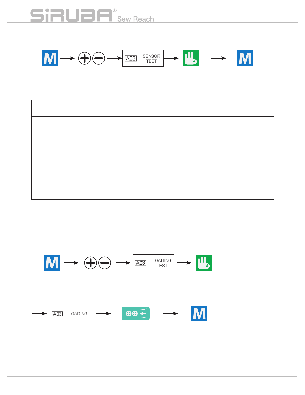
A02 SENSOR / 訊號檢測 A02 SENSOR / SIGNAL DETECTION
A03 入料動作測試 A03 test the action of filling material
※ 手動操作氣缸, sensor 有亮滅,且螢幕有 ON/OFF 切換表示正常;上 / 下極限開關用一金屬物靠近
以輔助判別 sensor 是否正常
※Users operate cylinder, sensor LED on/off well and screen shows ON/OFF switch -> machine is well;
use a metal rod to approach upper/lower limit switches to check if sensors are well.
按參數設定鍵
Press parameter
setting button
按項目選擇鍵
press select
button
選擇 A03
Select A03
進入測試模式
Enter test mode
按參數鍵 2 次回主畫面
Press parameter
button twice to move
back to home screen
按補料鍵執行入料動作
Press this button to
process filling material
按確認鍵進入設定
Press enter button to
enter the setting
IN1:前伸氣缸磁簧開關
IN1:Forward cylinder reed switch
IN7:成型區感應器
IN7:Sensor on forming part
IN2:塑型氣缸磁簧開關
IN2:Forming cylinder reed switch
IN8:原點位置磁簧開關
IN8:Reed switch on original point of suction cup
IN3:定位磁簧開關
IN3:Position reed switch
IN9:上極限開關
IN9:Upper limit switch
IN4:擋邊磁簧開關
IN4:Guide block reed switch
INA:下極限開關
INA:Lower limit switch
IN5:車縫踏板訊號
IN5:Sewing activation pedal signal
INB:有料判別開關
INB:Storage material detect
sensor
IN6:準備點位置微動開關
IN6:Micro switch on standby point of suction cup
INC:壓腳踏板訊號
INC:Presser foot pedal signal
按確認鍵進入設定
Press enter button
to enter the setting
按項目選擇鍵
press select
button
按參數設定鍵
Press parameter
setting button
按參數鍵 2 次回主畫面
Press parameter button
twice to move back
home screen
選擇 A02
Select A02
P29
Page 35

A04 步進馬達測試
A05 單 / 雙踏板方式選擇 A05 choose single/double pedals
版本顯示 Version display
按參數設定鍵
Press parameter
setting button
按參數設定鍵
Press parameter
setting button
按參數設定鍵
Press parameter
setting button
按項目選擇鍵
press select
button
按項目選擇鍵
press select
button
按項目選擇鍵
press select
button
按選擇鍵選擇
單 (1)/ 雙 (2) 踏板
Press select buttons to select
one(1)/ 2-step(2) pedals
選擇 A04
Select A04
選擇 A05
Select A05
顯示版本代號。
D_VER: 控制板版本
M_VER: 操作盒版本
Display version code
D_VER: control board version
M_VER: control box version
由選擇鍵
+ / - 選擇
馬達運轉方向
(+) 載料平台向上
( - ) 載料平台向下
Press select button
+ / - to choose
rotatory direction
of motor
Motor direction
(+) raise material
platform
( - ) lower material
platform
按參數鍵 2 次回主畫面
Press parameter
button twice to move
back to home screen
按參數鍵 1 次回主畫面
Press parameter
button once to move
back to home screen
按參數鍵 1 次回主畫面
Press parameter
button once to move
back to home screen
按確認鍵進入設定
Press enter button
to enter the setting
按確認鍵進入設定
Press enter button
to enter setting
按確認鍵確認方向
Press enter button
to decide direction
按確認鍵確認方向
Press enter
button to select
踩車縫踏板 (L), 馬達運轉
Tread activation pedal (L),
motor starts running
※ 選擇方向後須再次按下 確認鍵 ※Need to press enter button after choosing
direction
xx.xx.xx
xx.xx.xx
P30
Introduction
Page 36

故障排除 TROUBLE SHOOTING
•DC24V 電源供應器 •DC24V power supply
AC110/220V 電源輸入
AC110/220V
INPUT
PIN 符號 Symbol 說 明 Description
1 L AC220V 輸入 Input
2 N AC220V 輸入 Input
3 PE 接地 Ground
4 -V 0V
5 -V 0V
6 +V +24V
7 +V +24V
P31
Page 37

CN1 I/O 板連接埠 ( 排線連接 IO 板 CN1)
CN1 Control board port ( Flexile flat cable
connect with CN1 on control board )
CN1000 I/O 板連接埠 ( 排線連接 IO 板 CN2)
CN1000 Control board port ( Flexile flat cable
connect with CN2 on control board )
控制板 ( 一 ) CONTROL BOARD (I)
CN11 輸入控制
CN11 INPUT CONTROL
CN10 輸出控制
CN10 OUTPUT CONTROL
PIN 符號 Symbol 說明 Description PIN 符號 Symbol 說明 Description
1 VCC
外部輸入電壓
Input power
1 PC12
校正成型區感應器
Correcting sensor on forming part
2 VCC 備用 Spare 2 PC13 備用 Spare
3 PA11 車頭訊號 Machine head signal 3 PC14 車縫 Sewing
4 PA12 備用 Spare 4 PC15 壓腳 Presser foot
5-8 24V DC24V
J3 VCC2 跳帽電壓選擇埠
J3 VCC2 voltage select port for
jumper cap
J2 VCC1 跳帽電壓選擇埠
J2 VCC1 voltage select port for
jumper cap
J4 VCC 跳帽電壓選擇埠
J4 VCC voltage select port for
jumper cap
PI
符號
Symbol
說 明
Description
PI
符號
Symbol
說 明
Description
PI
符號
Symbol
說 明
Description
1 24V
DC24V 電源輸入
DC24V Power Input
1 24V
DC24V 電源輸入
DC24V Power Input
1 24V
DC3.3V 電源輸入
DC3.3V Power Input
2 VCC2 2 VCC1 2 MS2
馬達全 / 半步選擇
Full/half step motor select
3 5V
DC5V 電源輸入
DC5V Power Input
3 5V
DC5V 電源輸入
DC5V Power Input
3 GND GND
跳帽選擇 5V&COM
Jumper selects 5V&COM
跳帽選擇 24V&COM
Jumper selects 24V&COM
跳帽選擇 MS2&GND
Jumper selects MS2&GND
P32
Introduction
J3 J2 J4
CN11 CN10
CN1 CN1000
Page 38

CN9 ADC 信號輸入
CN9 ADC Signal Input
CN6 DC24V 輸入
CN6 DC24V Input
CN7 DC24V 風扇輸出
CN7 DC24V Fan Output
PIN
符號
Symbol
說 明
Description
線色 PIN
符號
Symbol
說 明
Description
PIN
符號
Symbol
說 明
Description
1 3.3V
3.3V 電源輸出
3.3V Power Input
紅 Red 1 24V
DC24V 電源輸入
DC24V Power Input
1 24V
2 GND GND 黑 Black 2 0V 2 0V
3 IN
ADC 信號輸入
ADC Signal Input
藍 Blue 3 FG 外殼接地 GND
4 NC
CN12 IIC 信號 ( 備用 I/O)
Spare for Signal I/O
CN8 操作盒通信接口
Communication Connector
CN4 步進馬達
CN4 Stepper Motor
PIN
符號
Symbol
說 明
Description
PIN
符號
Symbol
說 明
Description
PIN
符號
Symbol
說 明
Description
線色
1 GND GND 1 5V
5V 電源輸出
5V Power Output
1 CA
A 相中心點
A Phase center
白 White
2 PA8
壓腳踏板
Presser foot pedal
2 BOOT0 2 CB
B 相中心點
B Phase center
黃 Yellow
3 PB9
有料判別開關
Storage material
detect sensor
3 GND GND 3 A A 相 A Phas
e 紅 Red
4 PD2 備用 Spare 4 4 /A /A 相 /A Phase 藍 Blue
5 PB15
準備點位置微動開關
Reed switch on standby point
5 5 B B 相 B Phase 綠 Green
6 TX 6 /B /B 相 /B Phase 黑 Black
7 RX
信號輸入
Signal Input
8 GND GND
控制板 ( 二 ) CONTROL BOARD (II)
P33
CN9 CN4
CN12
CN8
CN7
CN6
Page 39

I/O 板 I/O BOARD
PIN 符號 Symbol 說明 Description
IN(X)_Pin1 P24 X=1~7 此接點為輸出 24V Output 24V on X=1~7
IN(X)_Pin3 GND 此接點為輸出 GND, GND output
IN(X)_Pin1 VCC
X=8~10 此接點可由 J1 跳帽選擇輸出 24V or 5V
Output 24V or 5V switched by jumper cap J1 on X=8~10
IN1~IN10 輸入信號 IN1~IN10 Input signal
IN 1_Pin2 IN1 前伸氣缸磁簧開關 Forward cylinder reed switch
IN 2_Pin2 IN2 塑型氣缸磁簧開關 Forming cylinder reed switch
IN 3_Pin2 IN3 定位氣缸磁簧開關 Position cylind
er reed switch
IN 4_Pin2 IN4 擋邊氣缸磁簧開關 Guide block cylinder reed switch
IN 5_Pin2 IN5 下極限開關 Lower limit switch
IN 6_Pin2 IN6 車縫踏板 Sewing activation pedal
IN 7_Pin2 IN7 上極限開關 Upper limit switch
IN 8_Pin2 IN8 成型區感應器 Sensor on forming part
IN 10_Pin2 IN10 原點位置磁簧開關 Reed switch on original point of suction cup
CN1 控制板連接埠 CN1 control port
( 排線連接控制板 CN1) (connector control board CN1)
CN2 控制板連接埠
CN2 control port
( 排線連接控制板 CN1000)
(connector control board CN1000)
P34
Introduction
IN10 IN7 IN4 IN1
IN8 IN5 IN2
IN9 IN6 IN3
CN2
CN1
Page 40

J1 VCC 跳帽電壓選擇埠 Jumper voltage select port
腳位
PIN
符號
Symbol
說明
Description
1 24V DC24V 電源輸入 DC24V Power Input
2 VCC
3 5V DC5V 電源輸入 DC5V Power Input
跳帽選擇 5V&COM Jumper select 5V&COM
J2 VCC2 跳帽電壓選擇埠 Jumper voltage select port
腳位
PIN
符號
Symbol
說明
Description
1 24V DC24V 電源輸入 DC24V Power Input
2 VCC2
3 5V DC5V 電源輸入 DC5V Power Input
跳帽選擇 24V&COM Jumper select 24V&COM
CN4 I/O 板輸出連接埠 CN4 I/O board output port
腳位 PIN 符號 Symbol 說明 Description
1 OUT 7 到位氣缸電磁閥 Arrival cylinder solenoid valve
2 OUT 8 擋邊氣缸電磁閥 Guide block cylinder solenoid valve
3 OUT A 備用 Spare
4 OUT 9 吸嘴氣缸電磁閥 Suction nozzle cylinder solenoid valve
5 OUT 10 吹氣氣缸電磁閥 Blowing cylinder solenoid valve
6 OUT B 備用 Spare
7~9 24V DC24V 電源輸入 DC24V power input
10~12 VCC2 J2 跳帽選擇 24V&COM J2 jumper cap selects 24
V&COM
CN3 I/O 板電磁閥連接埠 CN3 I/O board solenoid connection port
腳位 PIN 符號 Symbol 說明 Description
1 OUT 1 運料氣缸電磁閥 Transmission cylinder solenoid valve
2 OUT 2 前伸氣缸電磁閥 Forward cylinder solenoid valve
3 OUT 3 夾料氣缸電磁閥 Clamp cylinder solenoid valve
4 OUT 4 塑型氣缸電磁閥 Forming cylinder solenoid valve
5 OUT 5 翻轉氣缸電磁閥 Rotation cylinder solenoid valve
6 OUT 6 定位氣缸電磁閥 Position cylinder solenoid valve
7~12 24V DC24V 電源輸入 DC2
4V Power Input
J1
J2
CN3
CN4
P35
Page 41

檢查控制板和操作盒連接
的訊號線接頭是否鬆脫 ?
Check if signal cable
between control board
and control box is loose
or not
檢查訊號線外觀
是否有破損 ?
Visually check if
outlook of signal
damages or not
電表量測訊號線
兩端對應訊號
Use meter to
detect relative
cable signals
from both end
sides
重新接妥再測一次
Re-connect and check again
重新開機後再測試一次
Re-boot and test again
更換線材再測一次
Exchange cable and
check again
更換線材再測一次
Exchange cable and
check again
更新程式時重開
機 ?
Check if re-boot
when renewing
program ?
簡易維修流程圖 SIMPLE MAINTENANCE
U3 電路圖
U3 circuit diagram
CN6 電路圖
CN6 circuit diagram
P36
Introduction
YES
YESYES
NO
NO NO
出現錯誤代碼 E01:
通訊故障
ERROR CODE E01:
COMMUNICATION ERROR
U3
F1
CN6
Page 42

A. 無電源
Step 1. 檢查電源插頭是否完整插入 ?
Step 2. 檢查電源開關是否開啟 ?
Step 3. 檢查控制基板
a. 檢查控制板 LED 是否正常亮起 ?
b. 電表量測 CN6 是否為 DC24V?
c. 檢查 F1 ( 3.15A FUES) 是否燒斷 ?
d. 電錶量測 U3 是否為 5V 與 3.3V?
5V 量測 U3 Pin3 與 Pin1
3.3V 量測 U3 Pin2 與 Pin1
B. 步進馬達轉動異常
目測 U11 (SLA7073MRT ) IC 外觀塑膠部份是
否有裂痕 ?
A. No Power
Step 1.check if power connector fully plugs
in.
Step 2.check if power switch is on.
Step 3.check control board.
a.check LED of control board is on.
b.use meter to check
if CN6 is DC24V.
c.check if F1 ( 3.15A FUSE) burn out.
d.use meter to check if U3 is 5V or 3.3V.
5V check U3 between Pin3 and Pin1
3.3V check U3 between Pin2 and Pin1
B. stepping motor runs error
Visually inspect U11 (SLA7073MRT ) IC if
there is damage on plastic outlook.
U11
P37
LED
Page 43
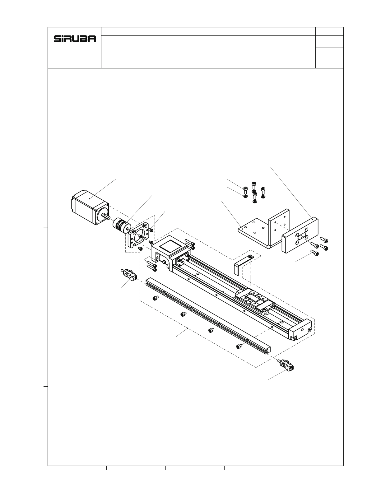
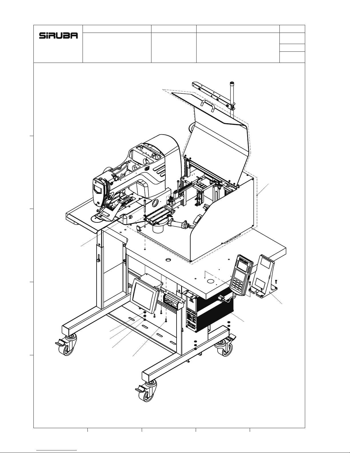
PARTS LIST
Series
Parts Group
Subclass Remark
Page
Date
1 2 3 4 5
E
D
B
C
A
PTA-0034
4-SM031
4-SM313N
4-WM310
PTA-0006
PTA-0007
4-SM311N
PTA-0321
PTA-0314
PTA-0315
PTA-0035
/
1 16
ASP-PTA100
PTA-0035-A
P38
Page 44
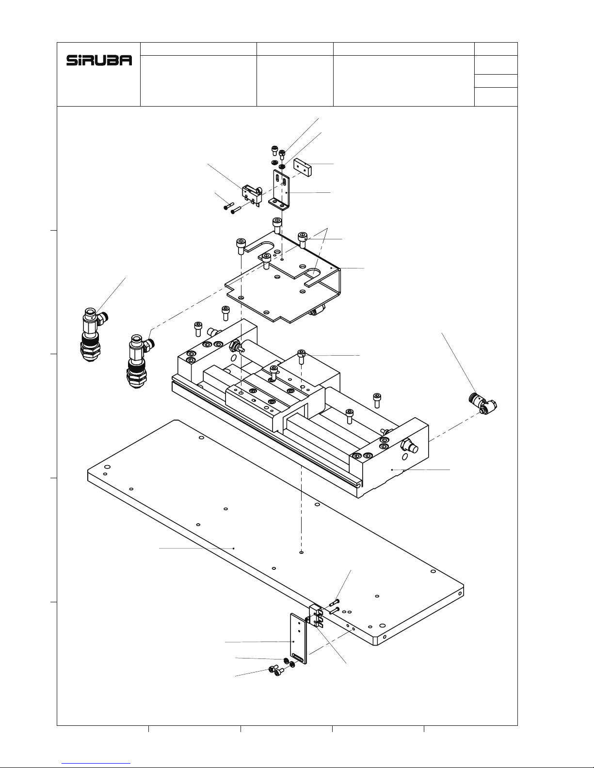
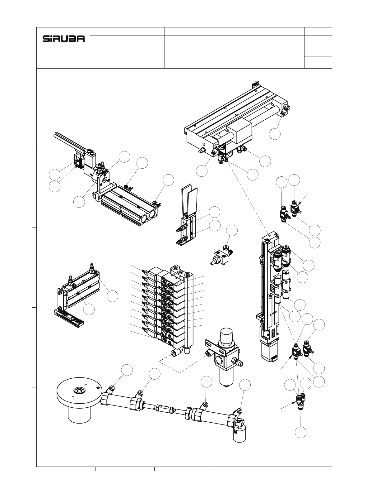
PARTS LIST
Series
Parts Group
Subclass Remark
Page
Date
1 2 3 4 5
E
D
B
C
A
UWB-0018
PTA-0011
2-SM310N
2-WM310
PTA-0320
2-SM233
4-SM510N
PTA-0010
2-PTA-0024
6-SM411N
2-JA291
PTA-0033
2-SM310N
PTA-0318
AC914
PTA-0003
2-WM310
2-SM233
/
2 16
PTA-0003-A
ASP-PTA100
P39
Page 45

PARTS LIST
Series
Parts Group
Subclass Remark
Page
Date
1 2 3 4 5
E
D
B
C
A
PTA-0004
2-SM4107N
JA045
2-PTA-0025
2-PTA-0023
2-SM516N
3-SM411N
2-SM411N
PTA-0012
PTA-0062
E449-E
2-SM310N
PTA-0036
2-PTA-0013
PTA-0032
PTA-0031
4-PM406
SM357
PTA-0002
/
3 16
PTA-0002-A
ASP-PTA100
P40
Page 46

PARTS LIST
Series
Parts Group
Subclass Remark
Page
Date
1 2 3 4 5
E
D
B
C
A
PTA-0035-A
4-PTA-0022
4-SM510N
SM418N
WM410
PTA-0020
PTA-0028
PTA-0005
2-PTA-0029
8-SM418N
2-PTA-0030
4-SM313N
PTA-0021
2-SM313N
2-WM310
5-PTA-0026
3-PTA-0008
5-SM404
2-JA0403
2-SM411N
2-WM410
2-WM4001
AC702
2-SM311N
2-PTA-0009
4-PTA-0015
PTA-0016
2-ASP-4088
8-SM031
2-PTA-0060
PTA-0001
/
4 16
ASP-PTA100
PTA-0005-A
P41
Page 47

PARTS LIST
Series
Parts Group
Subclass Remark
Page
Date
1 2 3 4 5
E
D
B
C
A
PTA-0003-A
PTA-0002-A
8-SM410N
4-WM410
3-SM411N
6-SM510N
2-ASP-0191
4-NM413
PTA-0018
9-SM4050
PTA-0017
ASP-0205
PTA-0019
PTA-0005-A
PTA-0027
/
5 16
ASP-PTA100
PTA-0019-A
P42
Page 48

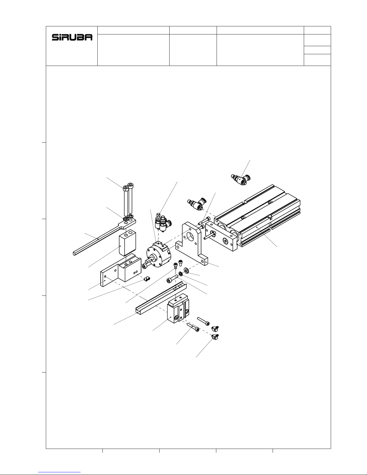
PARTS LIST
Series
Parts Group
Subclass Remark
Page
Date
1 2 3 4 5
E
D
B
C
A
PTA-0043
2-PTA-0042
2-EM070
PTA-0041
PTA-0039
AC332
AC331
PTA-0040
PTA-0037
2-BR1122
BR7200
PTA-0038
4-JA045
2-SM404
/
6 16
PTA-0038-A
ASP-PTA100
P43
Page 49
PARTS LIST
Series
Parts Group
Subclass Remark
Page
Date
1 2 3 4 5
E
D
B
C
A
PTA-0045
PTA-0048
AC718
2-SM3100N
2-JA213
2-SM4106N
2-WM410
2-WM407
2-SM310N
2-SM404
2-SM517
2-WM510
AC717
2-JA042
3-SM3100N
2-JA0403
AC606
PTA-0044
PTA-0072
PTA-0046
/
7 16
PTA-0045-A
ASP-PTA100
P44
Page 50

PARTS LIST
Series
Parts Group
Subclass Remark
Page
Date
1 2 3 4 5
E
D
B
C
A
SM814N
2-SM6104N
2-SM4108N
PTA-0019-A
PTA-0045-A
PTA-0038-A
/
8 16
PTA-0001-A
ASP-PTA100
P45
Page 51

PARTS LIST
Series
Parts Group
Subclass Remark
Page
Date
1 2 3 4 5
E
D
B
C
A
2-NM413
2-WM410
PTA-0051
2-JA042
2-SM4108NAC714
2-SM502
2-PTA-0055
2-PTA-0053
2-PTA-0054
PTA-0052
2-NM413
2-SM446
2-SM4074
PTA-0061
2-SM411N
2-WM410
2-WM407
/
9 16
PTA-0051-A
ASP-PTA100
P46
Page 52

PARTS LIST
Series
Parts Group
Subclass Remark
Page
Date
1 2 3 4 5
E
D
B
C
A
PTA-0067
SM337
WM310
PTA-0059
PTA-0058
SK4202
WM502
2-NM511
2-SM520
2-WM510
/
10 16
PTA-0058-A
ASP-PTA100
P47
Page 53

PARTS LIST
Series
Parts Group
Subclass Remark
Page
Date
1 2 3 4 5
E
D
B
C
A
PTA-0063
PTA-0058-A
2-ABF513
2-SM556N
2-SM310N
PTA-0057
PTA-0056
2-SM411N
2-WM407
2-WM410
PTA-0051-A
2-SM411N
LKS-1903ANSS
/
11 16
PTA-0100-A
ASP-PTA100
P48
Page 54
PARTS LIST
Series
Parts Group
Subclass Remark
Page
Date
1 2 3 4 5
E
D
B
C
A
4-SK8A1
4-KX09
4-SW07
8-NK45
2-WM601
2-WM610
2-SM6104N
PTA-0099-A
PTA-0050
4-SM4113N
PTA-0064-A
2-ASP-1243
2-WM8000
PTA-0100-A
2-ASP-4161
4-WM601
4-WM610
4-SM6108N
PTA-0049
ASP-0210-A
4-ASP-0211
4-ASP-0212
4-NK72
4-SM821N
4-WM810
4-WM8000
/
12 16
PTA-0049-A
ASP-PTA100
P49
Page 55

PARTS LIST
Series
Parts Group
Subclass Remark
Page
Date
1 2 3 4 5
E
D
B
C
A
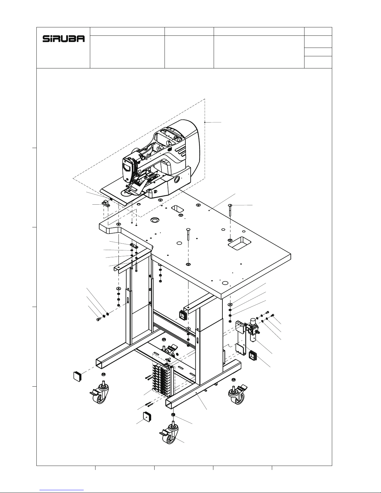
AMT-0011
DKT301ADE-1
BQ19
23-SM4837
PTA-0065
3-CP106
ASK-0074
AMT-0015
EPS001104
PTA-0323-E
PTA-0324-E
PTA-0069
4-SK392
FU102
/
13 16
PTA-0069-A
ASP-PTA100
P50
Page 56
PARTS LIST
Series
Parts Group
Subclass Remark
Page
Date
1 2 3 4 5
E
D
B
C
A
8-WM601
8-WM610
4-NM615
14-SK392
4-SM6109N
BN707
PTA-0069-A
PTA-0001-A
/
14 16
ASP-PTA100
ASP-PTA100
P51
Page 57

B
A
B
A
B
A
B
A
B
A
B
A
B
A
B
A
B
A
PARTS LIST
Series
Parts Group
Subclass Remark
Page
Date
1 2 3 4 5
E
D
B
C
A
黑
白
SV-1
2
氣源
1
4
夾具進給
3
夾具
整形
5
翻轉
6
黑
白
黑
黑
黑
白
黑
白
白
待進
Setting pressure:0.5Mpa
移載
SV-2
SV-3
SV-5
SV-6
#1A
#1B
1F
1
#2A
#2B
#3A
#3B
#5A
#6A
#6B 6F
6
5
2F
3F
3
2
inletoutlet
PTA-0099-A
AC914
AC702
AC331
(1)
(2)
(3)
(4)
(5)
(6)
(7)
(11)
(14)
(13)
(8)
JA225*2
AC718
AC717
SV-4
4F
4
#4A
#4B
白
(9)
(10)
黑
B
A
#5B
白 (12)
5F
AC606
(15)
(16)
AC332
7
7F#7B
#7A
SV-7
進料
白
黑
7
擋邊
8
AC714
8
8F
(18)
黑白(17)
#8A
#8B
SV-8
SV-9
SV-10
JA222*2
9
吸嘴
10
吹嘴
#9A
白
#10A
黑
(19)
(20)
(21)
(22)
(23)
(24)
(25)
(26)
(27)
(28)
#9
#9
#10
ASP-PTA100
/
15 16
氣壓流程圖
P52
Page 58
PARTS LIST
Series
Parts Group
Subclass Remark
Page
Date
1 2 3 4 5
E
D
B
C
A
#6A
#6B
#7B
#7A
#8B
#8A
#9
10
10
10
10
#4A
#4B
10
10
1B
1A
#2B
#2A
#5A
#5B
#3A
#3B
1B
1A
10
10
10
10
10
10
JA225*2
JA222*2
JA072
#1B
#1A
#1A
#2A
#3A
#5A
#4A
#6A
#7A
#8A
#9
#10
#1B
#2B
#3B
#4B
#5B
#6B
#7B
#8B
#10
/
16 16
ASP-PTA100
氣壓裝配圖
P53
Page 59

P54
Page 60

由於對產品的改良及更新 , 本產品使用說明書中與零件圖之產品及外觀的修改恕不事先通知 !
The specification and/or the equipment described in the instruction book and parts list
are subject to change because of modification with out previous notice
ASP-PTA100.JUN.2018
 Loading...