

Page 1
使用說明書
INSTRUCTION BOOK
700KS
Page 2
誌
Page 3

Introduction
索引
致使用者 TO THE OPERATORS 1
警告標籤
搬運縫紉機 MOVING THE SEWING MACHINE 2
縫紉機的安裝位置 THE INSTALLATION POSITION 2
規格 SPECIFICATIONS 3
各部件名稱 NAMES OF MAJOR PARTS 5
安裝 INSTALLATION 6
新機器啟用規定 HOW TO OPERATE THE NEW MACHINE 8
潤滑油之注入與更換 LUBRICATION AND DRAINAGE 8
穿線方法 THREADING 10
控線調整 ADJUST THREAD TENSION 11
INDEX
WARNING TAG
1
頁 /PAGE
換針方法 REPLACE THE NEEDLE 13
針距調整 ADJUST THE STITCH LENGTH 13
差動比調整 ADJUST THE DIFFERENTIAL FEED RATIO 14
更換切刀 REPLACE THE T
針高度之調整 ADJUST THE NEEDLE HEIGHT 17
押具調整 ADJUST THE PRESSER FOOT 17
送具調整 ADJUST THE FEED DOG 19
針與勾針之關係 THE RELATIONSHIP BETWEEN NEEDLE AND LOOPER 21
定位勾針線挑線凸輪 POSITION THE LOOPER AND TAKE-UP THREAD CAM 24
操作環境照明 LIGHTENING OF THE OPERATION ENVIRONMENT 25
操作者條件 CONDITIONS OF ALL OPERATORS 25
保養 MAINTENANCE 26
RIMMERS 1
6
報廢流程 DEMOLITION PROCEDURE 27
Page 4
致使用者
TO THE OPERATORS
• 我們非常感謝您使用本公司出品之超高轉
速直驅式直針鎖邊縫紉機 ( 拷克車 )。
• 請詳細閱讀此說明書,將使您更了解本機
器獨特之性能及正確的使用方法,進而提
高您縫製的效率及品質。
• 首先請您注意 : 請先注入潤滑油及確認馬達
之轉向為順時鐘方向,才可以啟動本機器。
警告標籤
• 縫紉機上有警告標籤。
• 當使用縫紉機時,請遵守標籤上的說明。
如果標籤脫落或模糊不清,請和購買商店
聯繫。( 圖 1)
• Thank you very much for using our Ultra
Hihg Speed Straight Needle Overlock/
Safety Stitch Machine.
• Before operating his machine Please study
this bock carejully undwrstand the junction
and jeatures of the machine.
• Then it will help you to crease your sewing
efciencyandquality.
WARNING TAG
• The following warning tags will be attached
on the sewing machine.
• Please obey the instruction of the labels
while using it. If the labels were fallen or
blurred, please contact the stores where
the machine was bought.(Fig.1)
警告標籤
Warning tag
• 安全防護裝置及 轉動方向。( 圖 2)
P1
護目鏡
Spectacles
護指器
Finger guard
圖 1 / Fig. 1
• Safety protection device and rotary
direction. (Fig.2)
轉動方向
Rotary direction
圖 2 / Fig. 2
Page 5
Introduction
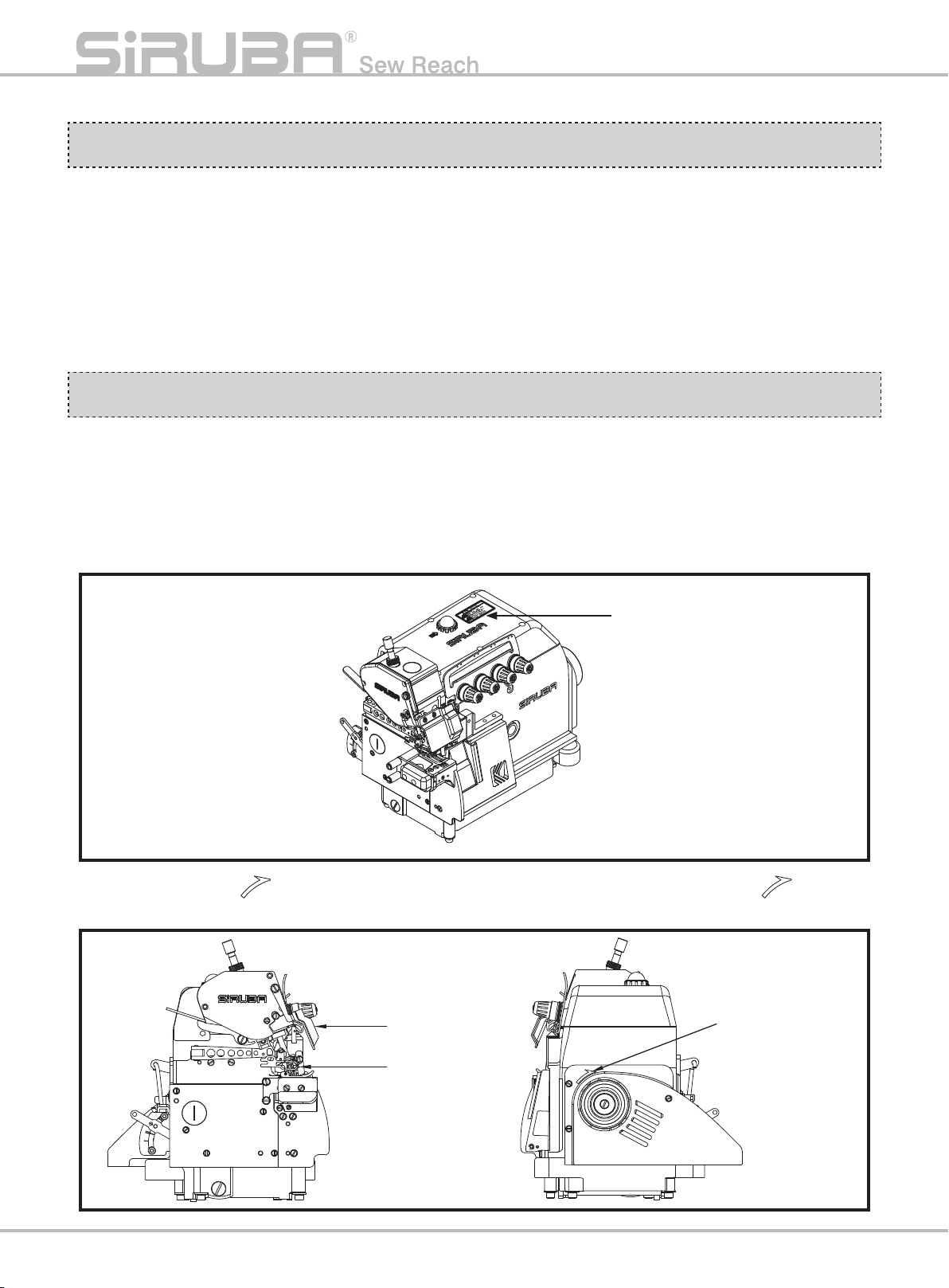
搬運縫紉機
• 應按圖適用左手托住前機殼本體,右手撐
扶住底盤進行搬運。( 圖 3)
• 搬運時需穿著安全鞋。
MOVING THE SEWING MACHINE
• Followtheinstructiongure,holethefront
cover of the machine with the left hand,
and then hold the bottom machine with
right hand to move it.(Fig.3)
• Should wear safety boots while moving.
圖 3 / Fig. 3
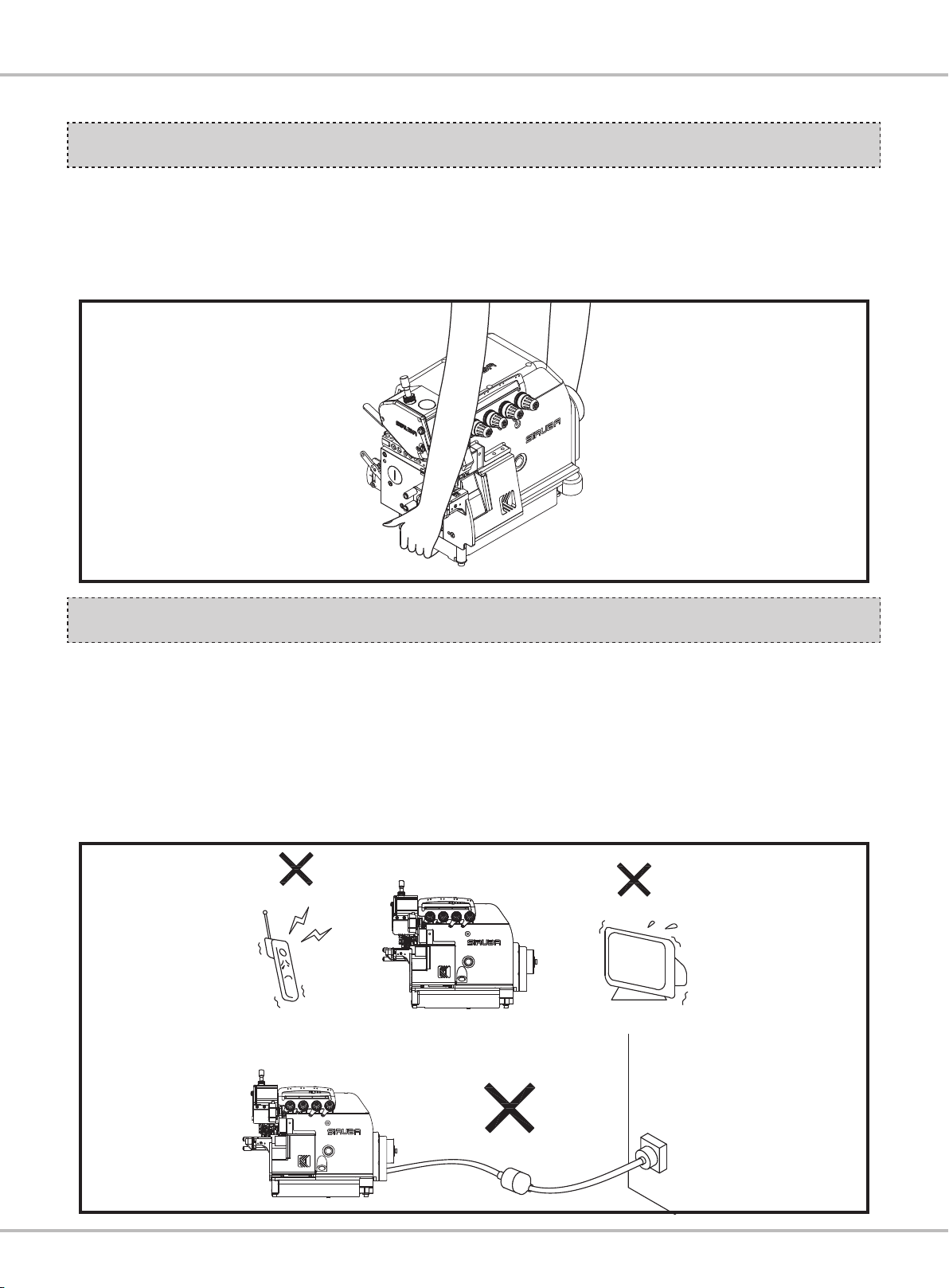
縫紉機的安裝位置
• 勿將該縫紉機置於設備附近,如電視機、
收音機或無線電話等,否則這些設備可能
會對縫紉機的電子干擾所影響。
• 應將縫紉機直接插入 AC 電源插座,如果
使用延長線,可能會造成操作故障。( 圖 4)
THE INSTALLATION POSITION
• Do not put the sewing machine around
the following devices, such as televisions,
radios or wireless telephones etc.
Otherwise, the electricity from these
devicescouldinuencetheperformance.
• Directly insert into AC power socket; using
extended cord could cause malfunction.
(Fig.4)
圖 4 / Fig. 4
P2
Page 6
規格 SPECIFICATIONS
型式
Type
型式
Type
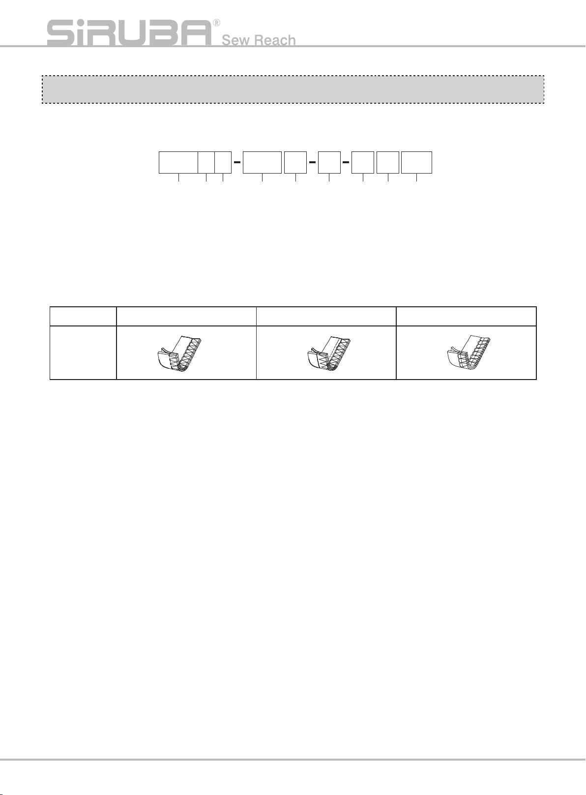
1. 外銷型號分類 :
1.Description:
747 514 M 3 2 4KS VT
(1) (2) (3) (4) (5) (6) (7) (8) (9)
(1) 線數 : 737 為 3 線、747 為 4 線
(2) 表示車台機構及外觀改良之區分編碼
(3) S:筒車
(4) 縫合方式 ( 圖表 1)
型式 Type 504 505 514
圖形
Pattern
圖表 1 / Chart1
(1)Thread Numbers:
(2)Distinguishing code for machine
mechanism and improved appearance.
(3)S: Cylinder bed
(4)Sewing types (Chart1)
3 for 737,4 for 747
(5) 車縫布料 :
F : 輕薄布料
L : 薄布料
M: 中厚布料
H: 厚布料
X : 特厚布料
(6) 送具型式 :
1: 標準 1 排
2: 標準 2 排
3: 標準 3 排
(7) 針寬 : 0: 單針 ; 2: 2mm
(8) 包邊寬度 :
3:3mm、4:4mm、5:5mm、6:6mm
(9) 搭配外掛多功能輔助件
(5)Sewing materials:
F : Fine weight material
L : Light weight material
M: Medium weight material
H: Heavy weight material
X: Extra heavyweight materia
(6)Feed dog type:
1: Standard first type
2: Standard second type
3: Standard third ty
(7)Needle Width: 0:single stitch; 2: 2mm
(8)Seam Width :
七 3:3mm、4:4mm、5:5mm、6:6mm
(9)Multi-function Attachment
pe
P3
Page 7
Introduction
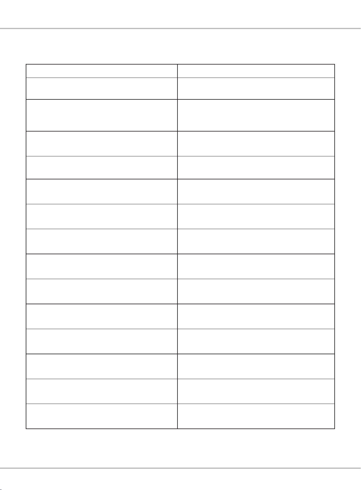
2. 規格說明 ( 表 1)
機型 Model 700KS
最高縫速
Max Stitch Speed
噪音值
Noise Level
縫距
Stitch Length
針棒行程
Stroke of the needle bar
押具揚程
Presser Foot Lift
押具壓力
Presser Foot Pressure
2.Specication(Table1)
6500rpm
80 分貝以下 under 80 dB
(5500rpm 測試數值 test value)
4 / 5 / 6 mm
24.3 ±0.2 mm
5mm
5kg
送具高度(凸出針板面)
Feed Dog Height (over the plate)
使用針
Needle for Use
送具傳動方式
Feed Dog Transmission
縫目調整裝置
Stitch Adjusting Device
押具裝置
Presser Foot Device
加油方式
Oil Filling
回油方式
Oil Return Solution
使用油
Oil for Use
0.8~1.0mm
DCX27
偏心輪、連桿
Eccentric, Connecting Rod
調整
按鈕
Button Adjustment
彈簧式、旋紐調整式
Spring Type, Knob Adjustment Type
儲油槽儲存方式,毛氈、棉線毛細管自動供油
Oil tank storage type. Automatic oil supply by Oil
felt, cotton thread capillary action.
偏心泵浦
Eccentric Pump
提供專用油 (MOBIL #10)
Provide Specic Oil (MOBIL #10)
表 1 / Table1
P4
Page 8
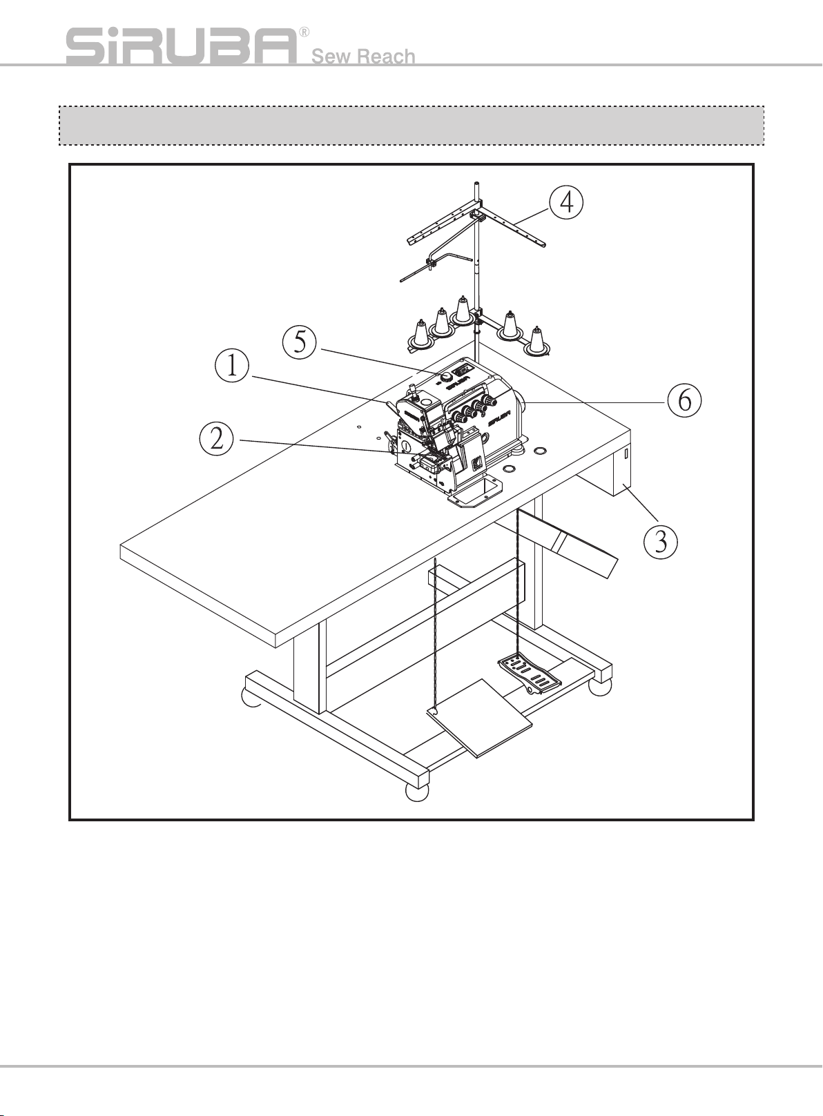
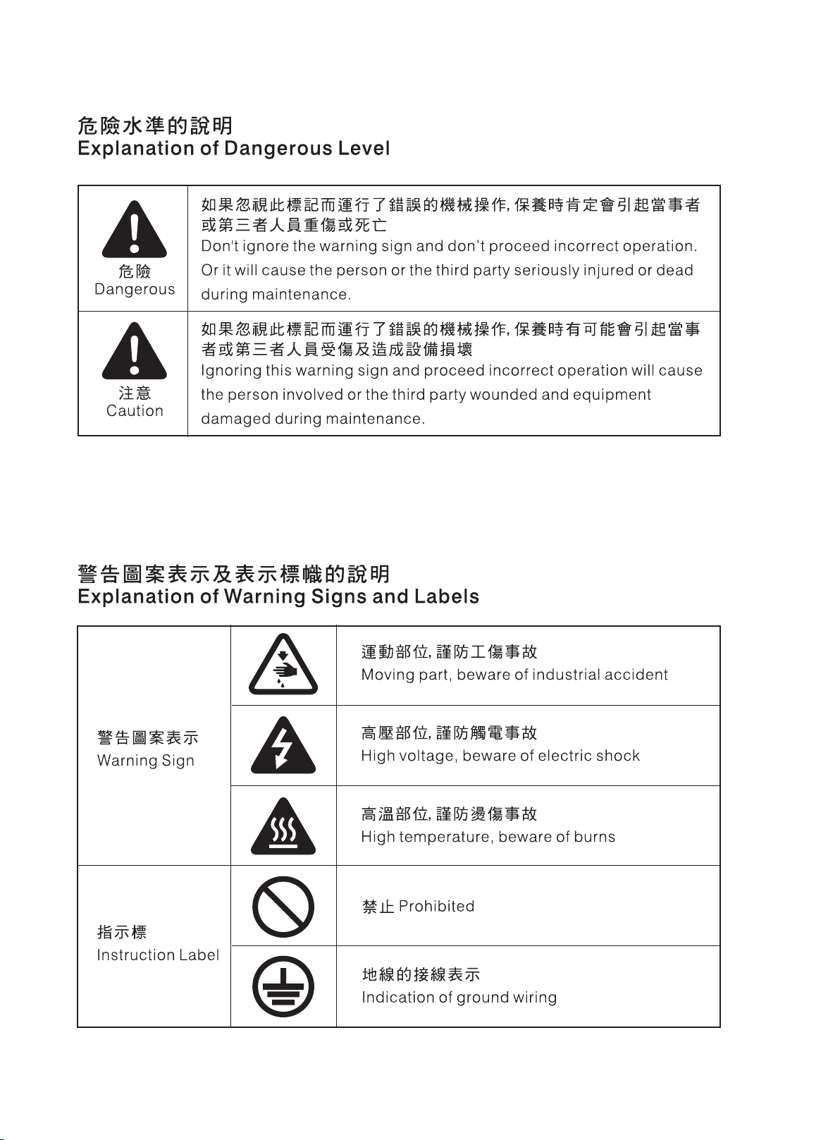
各部件名稱 NAMES OF MAJOR PARTS
(1) 押具扳手 ( 圖 5)
(2) 押具
(3) 控制箱
(4) 線架
(5) 油窗
(6) 手輪
P5
圖 5 / Fig. 5
(1)Lifting lever (Fig. 5)
(2)Presser foot
(3)Control box
(4)Thread stand
(5)Oil gauge window
(6)Pulley (Hand Wheel)
Page 9
安裝 INSTALLATION
Introduction
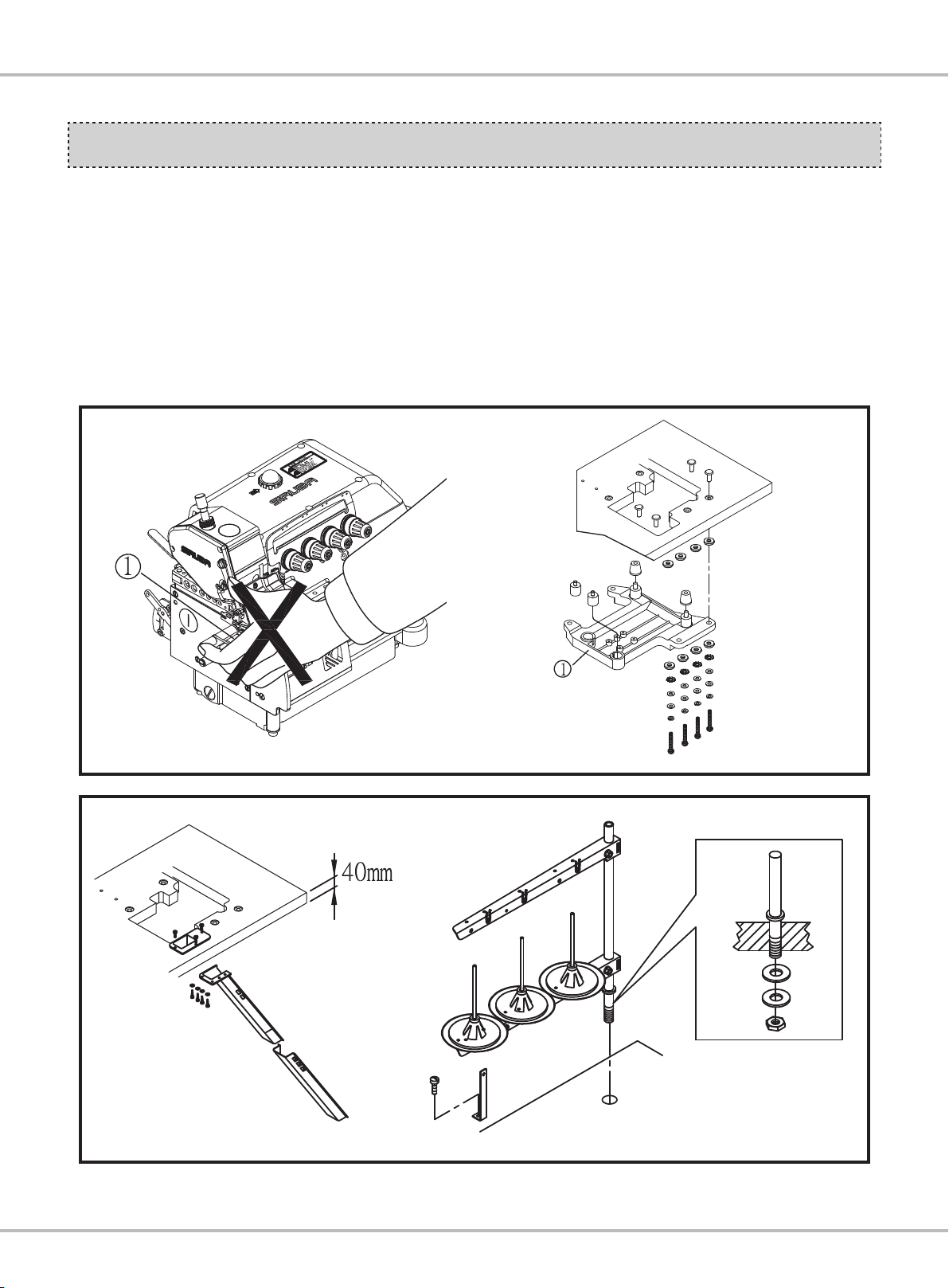
1. 縫紉機拆箱搬運過程中,不可扶持針座板①
下方。( 圖 6)
2. 依本機所附桌板裁製圖及零件組合圖所列之
配件,依序安裝防震機座鋁板 ②。( 圖 6)
3. 裝置導布屑及線架。( 圖 7)
1. While unpacking and moving the sewing
machine, do not hold under the stitch seat
plate1 .(Fig.6)
2. Based on the accessories attached with
the table cut-out drawing and components
drawings, install the shockproof machine
bed aluminum plate1. (Fig.6)
3. Install the waste fabric guide and the thread
stand. (Fig.7)
圖 6 / Fig. 6
圖 7 / Fig. 7
P6
Page 10

4. 馬達啟動踏板①裝於左邊, 押具腳踏板②則
裝於右邊。( 圖 8)
本體與車板不得干涉
4.Install the motor activating plate ① to the
left, and the presser pedal ② to the right.
(Fig.8)
圖 8 / Fig. 8
5. 注意馬達之轉向為順時鐘方向,皮帶①之鬆
緊度以用手指向內壓下縮 10mm 之緊度為
宜。( 圖 9)
6. 確保使用者的安全一定要鎖上皮帶護蓋②。
( 圖 9)
皮帶輪
Pulley
5.Pay attention to the motor rotation which
should be clockwise. The slackness of the
belt ① should be 10mm pressed down by
the nger.(Fig.9)
6.For the operators´safety, be sure to lock up
the belt cover ②.(Fig.9)
圖 9 / Fig. 9
P7
Page 11

Introduction
新機器啟用規定
1. 新機器在最初啟用磨合期的四個星期內,請
用低於最高速度 20%的速度運轉,之後換上
新潤滑油,才可運轉至最高速度。
2. 定期之清潔保養,確保延長機器之使用壽
命。
潤滑油之注入與更換
1. 潤滑油之注入 ( 圖 10)
(1) 油鏡①旋開,以包裝箱內所附之超高速潤滑
油或選用 MOBIL#10 或 AGIP # 32 等相當
之機油加入,使油量指示桿位於油標上下之
間即可,然後再鎖緊油鏡①。
(2) 開箱新機器或久置未使用時,請在針棒、上
勾針台等加油潤滑。
HOW TO OPERATE
THE NEW MACHINE
1. Please operate this machine in 80% of the
maximumspeedintherstfourweeksfor
engagement. After four weeks, please do
not operate under the maximum speed until
replacing the new lubrication oil.
2. Periodically maintain and clean the machine
to ensure and extend the usage term of the
machine.
LUBRICATION AND DRAINAGE
1.Fill the lubrication oil (Fig.10)
(1)Rem
(2)Please lubricate the needle bar and the
ove the oil level inspection leng ①,
and ll it with the attached ultra high speed
lubricating oil, or choose MOBIL#10 or
AGIP#32 equivalent. Tighten the oil level
inspection leng ① after the oil livel indicator
locates between the two marking lines.
upper looper shaft before starting operating
a new machine or a long idling machine.
2. 潤滑油之更換 ( 圖 10)
(1) 將螺絲②放鬆旋開,使油槽內的油完全排出
後再鎖緊。
(2) 為延長本機器之壽命,請於開始使用後四星
期更換新油,爾後約每四個月更換一次。
①
Upper limit
Lower limit
2.Drainage and rell th
(1)Loosen the screw ② and drain all the oil
inside the oil tank. Then, tighten the screw
again.
(2)In order to extend the term of usage, please
replace the oil after the rst four week, and
then replace it every four months.
②
e oil (Fig.10)
圖 10/ Fig.10
P8
Page 12

(3) 為延長此機器之壽命,特別裝有濾油器之機
構,請在每使用一個月後卸下清洗乾淨,必
要時得更換新品。
3. 針之冷卻油使用油 : 矽油 ( 圖 11)
(3)To extend the usage term, this machine has
equipped an oil lter. Please disassemble
and clean it every month, as well as change
it if needed.
3.Needle cooling lubrication oil: SILICON OIL.
(Fig. 11 )
Filter
圖 11 / Fig. 11
P9
Page 13

穿線方法 THREADING
Introduction
請確實按照圖示穿線,錯誤之穿線將引起斷
線、跳針及車縫不平坦 … 等現象。
1.737 用穿線圖 ( 圖 12)
Follow the procedures for threading. Wrong
threading may cause thread breaking, stitch
skipping, puckering or unexpected sewing.
1.For three thread only 737(Fig.12)
2.747 用穿線圖 ( 圖 13)
圖 12 / Fig. 12
2.For three thread only 747(Fig.13)
圖 13 / Fig. 13
P10
Page 14

控線調整 ADJUST THREAD TENSION
線張力必須根據縫合布料種類,布料厚薄,線
及包邊寬度等之差異而做不同的調整。順時針
旋轉張力控制螺帽,縫線張力加大,反之減弱。
1. 調整鈕之控線關係 ( 圖 14)
(1) 第一調整鈕①控制雙環針線或左邊拷克線。
(2) 第二調整鈕②控制包邊針線。
(3) 第三調整鈕③控制上勾針線。
(4) 第四調整鈕④控制下勾針線。
(5) 第五調整鈕⑤控制雙環勾針線。
The thread tension should be adjusted properly
according to the kinds and the thickness of
the materials, stitch length, and seam width,
etc. In addition, adjust the nuts case by case
individually. Turn the nuts
increase the thread tension. Otherwise, the
thread tension will be decreased
1. Thread tension adjusting nuts (Fig.14)
(1)The rst adjusting knob ① controls double
chain stitch threads or the left over-lock
needle thread.
(2)The second adjusting knob ② controls the
seam lock needle thread.
(3)The third adjusting knob ③ controls the
upper looper thread.
(4)The fourth adjusting knob ④ co
lower looper thread.
(5)The fth adjusting knob ⑤ controls the
double chain looper thread.
clockwisely will
ntrols the
P11
Weak
Strong
圖 14 / Fig. 14
Page 15

Introduction
2. 針線控線關係 ( 圖 15)
(1) 縫合方式 504、505、514 時,將過線組件
①移至最下端。
(2) + 表示增加針線放線量。
(3) - 表示減少針線放線量。
2.Relation of needle thread tension (Fig.15)
(1)While doing the stitches, 504,505,514, move
the eyelet ① to the bottom.
(2) + indicates to increase the thread amount.
(3) - indicates to decrease the thread
amount.
3. 勾針控線關係 ( 圖 16)
(1) 若縫合方式為 504 ,514 及上勾針移至最
低時,將①往 + 位置微調。若縫合方式為
505 時,則往 - 端微調。
(2) 固定線導板②、③如下:+ 方向為縫合線
較多,反之較少。
圖 15 / Fig. 15
3.Looper thread control(Fig.16)
(1)When the sewing type is 504, 514, and
the upper looper is on the lowest point,
adjust ① at the position of + . When the
sewing type is 505, set the take-up ① at the
position of - .
(2)Adjust xed thread guide plate ② and ③ as
the following: The direction + is for more
thread in sewing seam, and the - direction
is for less thread in sewing seam.
圖 16 / Fig. 16
P12
Page 16

換針方法
REPLACE THE NEEDLE
1. 使用 DCX27 或同規格之針。
2. 旋開螺絲①並取下針。
3. 將新針插至針孔最底端,並使針之長溝面向
自己,固定螺絲 ①。( 圖 17)
1.Please use the needle DCX27 or the
equivalents.
2.Loosen the screw ① and take off the needle.
3.Insert the new needle till reaching the end,
as well as the long groove faces your side.
Tighten the screw ①. (Fig.17)
①
針距調整
通常依縫合布料,差動比等之不同而調整。持
續壓下按鈕①並轉動手輪使鈕卡住,轉動手輪
至所需之針距後放開此按鈕。( 表 2)( 圖 18)
最大差動比
Maxi Diff ratio
1:1.3 包邊 Serging 0.8 1.5 2.2 2.9 3.6 4.3 5
1:2 接縫 Seaming 0.6 1.13 1.66 2.19 2.72 3.25 3.8
1:3 摺縫 Shirring 0.6 1.03 1.46 1.89 2.32 2.71 3.2
1:4 特規 Special 0.6 1.02 1.44 1.66 2.88 2.7 -
機種
Machine type
1 2 3 4 5 6 7
表 2 / Table2
ADJUST THE STITCH LENGTH
The stit
fabrics, the differential ratio or other factors.
Keep pressing the button ① and turn the
pulley till the button is locked. Then, release
the button after reaching the desired stitch
length.(Table2)(Fig.18)
ch length is adjusted according to the
皮帶輪刻度 Pulley scale
圖 17 / Fig. 17
P13
Page 17

Introduction
差動比調整
若主送具之運動行程大於差動送具運動行程
時,布料車縫時會伸張,反之則會收縮。
1. 調整方法一:
放鬆調整鈕①,當調整桿②向下調整時使布
料收縮,反之則伸張,調整後再鎖調整鈕①。
( 圖 19)( 表 3)
圖 18 / Fig. 18
ADJUST THE DIFFERENTIAL
FEED RATIO
If the stroke of the main feed dog is larger
than the stroke of the differential feed dog,
the fabric will be extended while sewing.
Otherwise, it will be shrunk
1.Adjust solution 1:
Loosen the adjusting nut ①. Adjust the
adjusting rod ② downward will shrink the
fab
ric, whereas move it upward will extend
the fabric. Tighten the adjusting nut ① after
the adjustment nishes. (Fig.19)(Table3)
P14
Page 18

刻度 Scale 1 2 3 4 5
1:1.3 - 1:0.7 1:0.9 1:1.1 1:1.3
差動傳送比
Differential feed ratio
1:2 1:0.7 1:1 1:1.14 1:1.17 1:2
1:3 1:1 1:1.5 1:2 1:2.5 1:3
1:4 1:1.1 1:1.6 1:2.3 1:2.3 1:3.3
表 3 / Table3
2. 調整方法二 :
(1) 鬆開蓋板①。
(2) 鬆開螺絲②,上下移動連桿③欲增加行程,
把連桿③往 (+) 方向移動 ; 欲減少行程,把
連桿③往 ( - ) 方向移動。
(3) 在調整過後,把蓋板①鎖回。( 圖 20)
圖 19 / Fig. 19
2.Adjusting manner2:
(1)Loosen the cover board ①.
(2)Loosen the screw ②.Move the lever ③ up
and down.To increase the stroke, move the
lever ③ to the (+) direction.To decrease the
stroke, move the lever ③ to the (-) direction.
(3)After adjusting, tighten the cover board ①.
(Fig.20)
圖 20 / Fig. 20
P15
Page 19

Introduction
更換切刀 REPLACE THE TRIMMERS
1. 更換上切刀 ( 圖 21)
(1) 取下螺絲①將上刀座②移出,鬆開螺絲③,
更換刀片④
(2) 轉動皮帶輪使上刀移至下死點,調整上刀
高低使上刀與下刀相交約 0.5~1.0mm,鎖
緊螺絲③。
(3) 試驗上下刀能確實剪斷車縫線。
2. 更換下切刀 ( 圖 21)
(1) 放鬆螺絲⑤將下刀座⑦向右移出。
(2) 放鬆螺絲⑥及固定片⑧更換刀片⑨。
(3) 將下刀座向左推回,調整下刀之刀口與針板
面平齊後,鎖緊螺絲⑤。
(4) 試驗上下刀能確實剪斷車縫線。
1.Replace the upper knife (Fig.21)
(1)Take down the screw ① and move out the
upper knife bracket ②. Loosen the screw ③
and replace the knife ④.
(2)Turn the pulley to m
the bottom dead point. Adjust the height of
the upper knife, and make the engagement
between the upper and lower knives to be
0.5~1.0mm. Then, tighten the screw ③.
(3)Test the upper and lower knives to cut the
thread.
2.Replace the lower knife (Fig.21)
(1)Loosen the screw ⑤ and move the lower
knife bracket ⑦ rightward.
(2)Loosen the screw ⑥ and the xed plate ⑧
and replace th
(3)Push the lower knife bracket back. Align the
blade of the lower knife to the needle plate,
and then tighten the screw ⑤.
(4)Test the upper and lower knives to cut the
thread.
ove the upper knife to
e knife ⑨.
圖 21 / Fig. 21
P16
Page 20

針高度之調整
ADJUST THE NEEDLE HEIGHT
1. 轉動皮帶輪使針上昇至最高點時,針尖至針
板面之距離為 (a)。( 圖 22)
2. 調整 :
(1) 打開上蓋①。
(2) 放鬆螺絲②,移動針棒至所需高度鎖緊螺絲
②。
(3) 回覆上蓋須密合鎖緊。
1.Turn the pulley to raise the needle to the top
point. The distance between the tip of the
needle to the needle plat
2.Adjustment:
(1)Open the upper cover ①.
(2)Loosen the screw ②, and move the needle
bar to the required height. Then, tighten the
screw ②.
(3)Put the upper cover back and lock it closely.
Standard
High stroke
e is (a). (Fig.22)
押具調整
1. 押具位置調整
(1) 放鬆押具壓力①及押具螺絲②。
(2) 移動押具③使其押具槽與針板之針槽一致
押具底平押於針板上,鎖緊螺絲②。
(3) 放鬆螺絲④左右移動⑤,使⑥與⑦吻合,且
⑥能上下活動輕順,鎖緊螺絲④。
(4) 調整適當壓力,螺絲①順時針方向旋轉,壓
力加大,反之減弱。( 圖 23)
圖 22 / Fig. 22
ADJUST THE PRESSER FOOT
1.Adjust the position of the presser
(1)Loosen the pressure of the preser ① and
the screw of the presser ②.
(2)Move the presser ③ to align the groove
of the needle plate and the groove of the
presse
touches the needle plate atly. Then, tighten
the screw ②.
(3)Loosen the screw ④ and move ⑤ right-left
to engage ⑥ with ⑦ and ⑥ could move
smoothly. Then, tighten the screw ④.
(4)Adjust the appropriate pressure. Turn the
screw ① clockwise to enlarge the pressure.
The opposite way lowers down the
pressure. (Fig.23)
r. The bottom side of the presser
P17
Page 21

Introduction
Weak
2. 押具提升量調整
(1) 轉動皮帶輪使送具降至針板下,壓具底平貼
針板。
(2) 放鬆螺帽①,壓下拉桿②使押具⑦上昇至
適當位置約 5.0~5.5mm,調整螺絲③及固
定螺帽①。
(3) 拉桿④與固定座⑤須保持有 1mm 的間隙
可輕輕放鬆螺絲⑥調整。
(4) 要確實鎖緊螺絲⑥。( 圖 24)
Strong
圖 23 / Fig. 23
2. Adjust the arising amount of the presser
(1)Turn the pulley to lower feed dog down
under the needle plate. The bottom side of
the presser touches the needle plate atly.
(2)Loosen the nut ①, push down the lever ②
to arise the presser
position, around 5.0 ~5.5mm. Adjust the
screw ③ and x the nut ①.
(3)Maintain the clearance between the lever ④
and the xed plate ⑤ to be 1mm. Loose the
screw ⑥ to adjust.
(4)Then, tighten the screw ⑥ rmly. (Fig.24)
⑦ to the appropriate
圖 24 / Fig. 24
P18
Page 22

送具調整 ADJUST THE FEED DOG
1. 送具高度調整 ( 圖 25)
(1) 轉動皮帶輪使送具上升至針板上最高點。
(2) 放鬆螺絲①,上下移動主送具②,使其齒面
高出針板面約 0.8 ~ 1.0mm ,鎖緊螺絲①。
(3) 放鬆螺絲③,上下移動差動送具④使其齒面
高出針板面約 0.8 ~ 1.0mm 鎖緊螺絲③。
1.Adjust the feed dog height(Fig.25)
(1)Rotate the pulley to rise the feed dog the
highest point of the needle plate.
(2)Loosen the screw ① , and move the main
feed dog ② u
the teeth side over the needle plate about
0.8 ~ 1.0mm. Then tighten the screw ①.
(3)Loosen the screw ③ , and move the
differential feed dog ④ up and down in
order to keep the teeth side over the needle
plate about 0.8 ~ 1.0mm. Then, tighten the
screw ③.
p and down in order to keep
2. 送具水平調整
(1) 當送料桿升至最高點時,送具齒面必須由前
向後傾斜。
(2) 調整時放鬆螺絲①②,轉動螺絲③進行調
整,齒面呈水平後固定螺絲①②。( 圖 26)
圖 25 / Fig. 25
2. Adjust the level of the feed dog
(1)When raising the feed bar to the highest
point, the side of the feed teeth must
tilted from the front to the back.
(2)Loosen the screw ①②, turn the screw ③ to
adjust. Make the side of the feed teeth and
then tighten the screw ①②. (Fig.26)
be
P19
圖 26 / Fig. 26
Page 23

Introduction
3. 輔助送布齒高度
輔助送具① ,其齒面比送布齒齒面低
0.1~0.3mm,可放鬆螺絲②來調整。
( 圖 27)
3. The height of the auxiliary feed teeth
The auxiliary feed dog ①, the side of teeth
is lower 0.1~0.3mm than the teeth side of
the feeder. Loosen the screw ②to adjust.
(Fig.27)
0.1~0.3mm
圖 27 / Fig. 27
4. 主送布齒與針板之關係
當設定送料量為最大時,需確認主送齒與針
板狹縫留有 0.8mm 的距離。( 圖 28)
4. Relation between the main feeder and the
needle plate
When setting the feeding amo
largest, it is necessary to conrm the
distance between the main feeder and the
needle plate is 0.8mm. (Fig.28)
unt is the
圖 28 / Fig. 28
P20
Page 24

針與勾針之關係
THE RELATIONSHIP BETWEEN
NEEDLE AND LOOPER
1. 針與上勾針之關係
當上勾針移至最左時,勾針尖端與針中心距
約 4.4 ~ 4.7mm ,雙針時其左針中心與勾
針尖端距約 5.4 ~ 5.7mm 。( 圖 29)
1.The relationship between the needle and the
upper looper
When the upper looper moves to the leftest
point, the distance from the looper tip to the
middle line of the needle is 4.4 ~ 4.7mm.
For double needles model, the distance from
the looper tip to the middle line of t
needle is 5.4 ~ 5.7mm.(Fig.29)
he left
2. 針與下勾針之關係
(1) 當下勾針移至最左時,勾針尖端與針中心
距約 2.8~3.0mm( 雙針時以左針為主 )。
( 圖 30)
圖 29/ Fig. 29
2. Relation between the needle and the looper
(1)The distance between the tip of the looper
and the center of the needle should be
2.8~3.0mm when the lower looper moves
the extreme left. (The left needle is main
while using double needles) (Fig.30)
P21
圖 30 / Fig. 30
Page 25

Introduction
(2) 依照桌板,調整下勾針A的距離設定, 下
勾針會從第一針孔穿過 1.3mm 的位置。
( 圖 31)
(3) 當下勾針向右移至針中心時 ( 雙針以左針 )
針與勾針之間隙為 0~0.05mm。( 圖 31)
(2)Based on the table, adjust the distance
setting of the lower lopper A. The lower
looper will pass from the rst needle hole
through the position of 1.3mm. (Fig.31)
(3)The clearance between the needle and the
looper is 0~0.05mm, wh
moves rightward to the center of the needle
(The left needle is main while using double
needles) (Fig.31)
en the lower looper
3. 上勾針與下勾針之關係
當上下勾針相交時,兩勾針盡量接近,但不
可磨擦或碰撞,其間隙 A 點為 0.5mm B 點
為 0.2mm。( 圖 32)
圖 31 / Fig. 31
3. Relation between the upper looper and the
lower looper
When the upper and the lower loopers
meet, they reach each other as close as
possible, but should not rub or hit each
other. The clearance of point A is 0.5mm
and the B point is 0.2mm. (Fig.32)
圖 32/ Fig. 32
P22
Page 26

4. 調整針與護針片之間隙
(1) 調整後護針片的方位
當下勾針尖移至針中心點時,後護針片①輕
觸車針, 兩者之間間隙為 0mm。調整方式
為放鬆螺絲②移動後護針片①以調整之。
( 圖 33)
(2) 調整前護針片的方位
當下勾針尖移針中心線時,前護針片 ③ 與
針之間隙為 0.05mm ~ 0.10mm。調整方法
為放鬆螺絲④ ,並移動前護針片③以調整
之。( 圖 33)
5. 針與護針片之關係
(1) 當下勾針由左向右至針中心時 ( 雙針以左
針 ) 針與後護針片之間隙為 0~0.05mm。
(2) 當針在下死點時針與前護針片之間隙為
0.1~0.2mm。( 圖 33)
4. Adjust the clearence between the needle
and the needle guard.
(1)Adjust the rear needle guard
When the tip of the lower looper m
oves to
the center of the needle, the rear needle
guard touches the needle gently. The
clearance between these two is 0mm.
Adjusting manner is to loosen the screw
② and move the rear needle guard ① to
adjust. (Fig.33)
(2)Adjust the front needle guard
When the tip of the lower looper moves
to the center of the needle, the clearance
between the front needle guard ③ and
the needle is 0.05mm~0.10mm. Ad
justing
manner is to loosen the screw ④ and move
the front needle guard ③ to adjust. (Fig.33)
5. Relation between the needle and the needle
guard
(1)When the lower looper moves from left to
right, to the center of the needle (The left
needle is main while using double needles),
the clearance between the needle and the
needle guard is 0~0.05mm.
(2)When the needle is at the bottom dead
point, the clea
rance between the needle
and the needle guard is 0.1~0.2mm.
(Fig.33)
P23
圖 33 / Fig. 33
Page 27

Introduction
定位勾針線挑線凸輪
POSITION THE LOOPER AND
TAKE-UP THREAD CAM
圖 34 / Fig. 34
針型式 Needle Type 504 505 514 504 514 504 514
勾針能力 Looper S H H SH
A 21.5 21.5 21.5 21.5
B 14.5 14.5 17.5 17.5
C 20 28 28 25
D 29 29 29 29
E 28 28 25 30
F Left Left Left Right
G Left Left Left Right
表 4 / Table4
P24
Page 28

操作環境照明
LIGHTENING OF THE
OPERATION ENVIRONMENT
Provide a warning that an industrial sewing
unit or sewing system must always be
unplugged from the local lighting of the
sewing area before relamping, the marking of
maximum rated input of lamp shall be easily
discernible while the lamp is being replaced
indicated on or near the lamp socket as shown
on.
提供一個警示標誌,告知使用者:工業
用縫紉品或是縫紉系統必須在該縫紉區
域未啟動照明裝置前,禁止插電或通
電;照明裝置的最大輸入功率應該能夠
輕易辨識,當照明裝置被重置或移動的
時候,警示標誌也應設置在照明裝置插
座上或是附近。警示標示如圖所示。
1. Read and understand well the content of
this instruction book.
2. Know the functions of major parts and
understand the notices
3. Truly realize the meanings of all warning
tags
4. Realize and be familiar with how to operate
this machine.
5. Operators have to keep well mental status.
6. Operators shall wear appropriate and
proper working suits.
7. Develop the familiarity of how to operate the
machine if needed.
1. 熟讀並了解使用說明書內容。
2. 認識機器各部功能及注意事項。
3. 了解各警告標籤之意義。
4. 了解熟悉機器之操作方式。
5. 操作者須保持精神狀態良好。
6. 操作者須穿著合宜適當之工作服。
7. 視需要培養操作者使用機器之熟練度。
操作者條件
CONDITIONS OF ALL
OPERATORS
( 圖 35)
(Fig.35)
圖 35 / Fig. 35
P25
Page 29

Introduction
保養
MAINTENANCE
啓
Periodical Maintenance Items
定期保養項目
保養循環
Maintenance Cycle
保養項目
Maintenance Items
每天
Daily
1. 清潔送料具上之棉絮
1. Clean the lint on the feed dog.
2. 檢查油盤是否有足夠之液態油。(油量在油鏡之上、下兩紅漆記號
間)
2. Check if there has enough liquid oil inside the oil pan. (The amount
should be between the red up and down paint mark of the oil level
gauge.)
3. 保持機器及操作台清潔
3. Keep the machine and the operation table clean.
4. 清潔手輪濾網上之棉絮
4. Clean the fiber on the filter net of the hand wheel.
每週
Weekly
1. 保持電源外觀乾淨
1. Keep the power cords looking clean and neat.
2. 保持操作面板乾淨
2. Keep the operational panel clean
3. 檢查電源零件是否鬆脫或在正確位置
3. Check if the power parts is loosening or still at the right position
每三個月
Quarterly
1.更換油盤內之液態油
1. Change the liquid oil inside the oil pan
( 表 5)
(Table5)
表 5 / Table5
P26
Page 30

報廢流程 DEMOLITION PROCEDURE
1. 當機器需要被淘汰與報廢時,有一些基本規
則必須採納、遵守以保護環境及公眾健康。
2. 所有的機器零組件必須依照下列分類來區分
開:
(1) 所有護套、可伸縮軟管及塑膠或非金屬零
件。
(2) 電器零件:開關、照明器具等。
(3) 絕緣材料:石棉、彈性/可伸縮橡膠片。
(4) 金屬:含鐵金屬、銅、青銅與黃銅、其他各
種金屬。
3. 以此方法,所有材質可以正確的淘汰,回收
再利用或鎔解為可再使用或再處理而不至於
危害環境。
1.When the machine needs to be eliminated
and demolished, certain basic rules must
be observed to protect the environment and
public health.
2.All machine componenets
according to categories as the followings:
(1)All sheathes, exible hosing and plastic or
non-metal components.
(2)Electricity components: switches, or lighting
components.
(3)Insulation materials: rock wool, and exible
rubber strips.
(4)Metals: ferrous metals, copper, bronze and
brass, various.
3.In this way, all materials can be eliminated
correctly, recycled, or melted down fo
or disposed of so that they do not harm the
environment.
must be divided
r reuse
P27
Page 31

由於對產品的改良及更新 , 本產品使用說明書中與零件圖之產品及外觀的修改恕不事先通知 !
The specification and/or appearances of the equipment described in this instruction
book & parts list are subject to change because of modification which will without
previous notice.
700KS.OCT.2014
 Loading...