

Page 1
flm~a~w
INSTRUCTION BOOK
700F
·1~
CE
F41®
~
iR~Jii1Bf5iPSDaJ
KAULIN MFG.CO
..
LTD.
Page 2

Page 3
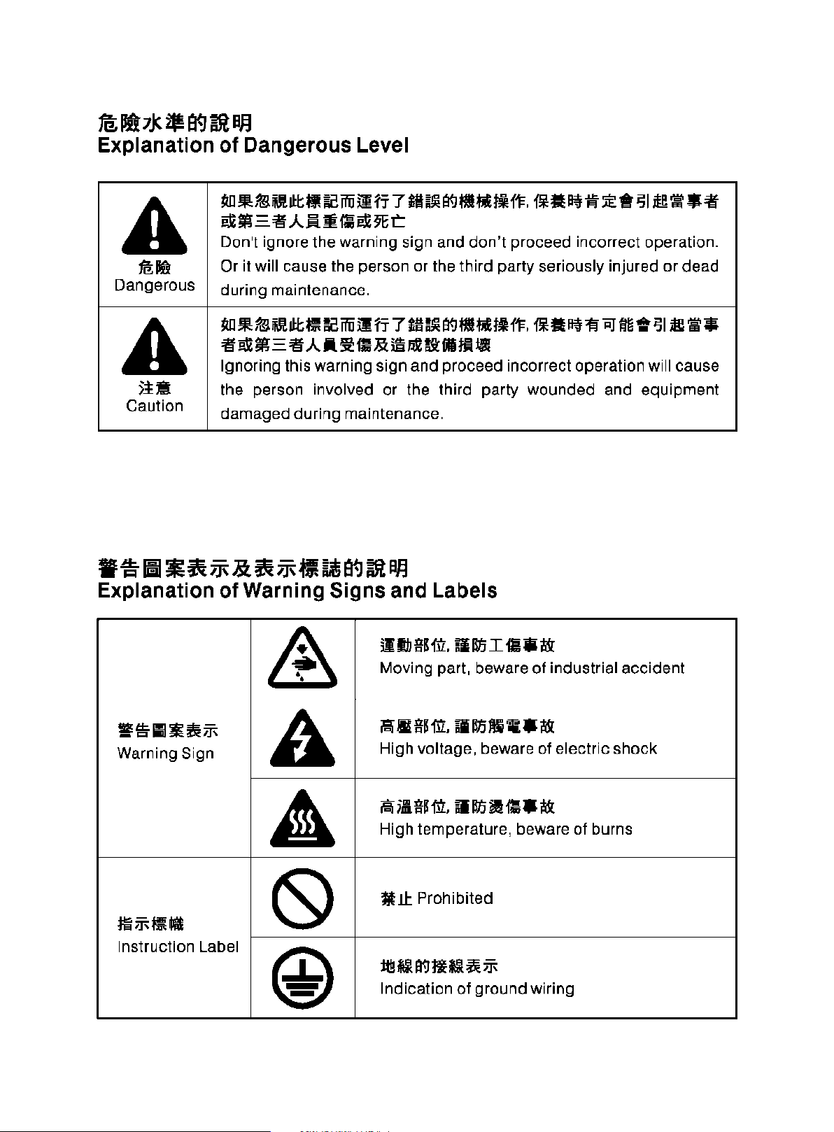
ta;
llff7Jc
Explanation
2IH19
A
~Jijk
Dangerous
A
).!!l
Caution
~
PF.1
of
Dangerous Level
~IL~
$ill!
ill:;
81
~
iffi
i1 rr 7 til
..
;(l='i!'.A..!l.J!~
Don't ignore the warning sign and
Or
it
will
cause the person or the third party seriously injured or dead
during maintenance.
~mm~Jll:;~~iffi~rr7~~a<JI!IIl'~~il!•~•~~•~I~\O!*
'~~'"";r!-'I!'.A.A~m~~~~-~~
Ignoring this warning sign and proceed incorrect operation will cause
the person involved or the third party wounded and equipment
damaged during maintenance.
..
9Et:
~
a<J
1!111'
1¥
don't
11',
ill
lit
~ ~
:;E
*
~
I
i!e
\0!
!II
'II'
proceed incorrect operation.
-~~~~1.1'&~1.1'-l!i.&atJ~PF.I
Explanation
of
Warning Signs and Labels
lllb
f!l'fil.
Moving part, beware
ill
lt'i
I
filii
I&
of
industrial accident
&
1fiS-III*~ff;
Warning Sign
A
i'UU!'fil. lllt'iMi 'ill
High voltage, beware of electric shock
F-\
iUI'fil.
High temperature, beware of burns
lllt'i
.I&
l!
m•l&
A
:lll;J<I~Ull
(S)
Instruction Label
@
¥!1: Prohibited
il!!~a<Jli~
Indication
...
;j;
of
ground wiring
Page 4

Page 5
I
I
,---
----------------------
i
-~~
---
------------------
INDEX
- --
---------------------------------------
---·
J{/PAGE
TO
Jf{ilf.l=!f
-6:~~-Jji~!Jl
·-~~*JRN!Jl
~HU*li
iltt~~·~
ltiiMjjj.a
MM.J.a!J9~ltfl!ll
m~
§BSf~:Sfll
ffiWHmmmj£
ALL
GENERAL SAFETY INSTRUCTIONS
IMPORTANT SAFETY INSTRUCTIONS
WARNING
WARNING
SAFETY ILLUSTRATION
MOVING THE SEWING MACHINE
THE INSTALLATION POSITION
SPECIFICATON
NAMES OF MAJOR PARTS
INSTALLATION
HOW TO OPERATE
USERS
TAG
OF
THE NEEDLE GUARD
THE NEW MACHINE
1
1
3
7
8
9
9
10
11
13
14
15
f4
51
5IB Z $1
A.
JB!!
}t
v•1i$
l!.JV.
fttiJJ$
tf-BEi-1.
~lbl:l::~-
tl
11=
Jl
t.i
IH~
jl
11=
=if
·1~
fia
i!&lllftl.
-~·
fi.flljM~
LUBRICATION
THREADING
ADJUST
REPLACE
ADJUST THE STITCH LENGTH
ADJUST THE DIFFERENTIAL FEED RATIO
LIGHTENING
CONDITIONS OF
MAINTENANCE
TOUB
TABLE CUT-OUT
DEMOLISTION PROCEDURE
THREAD TENSION
LESHOOTING
AND
DRAINAGE
THE NEEDLE
OF
THE OPERATION ENVIRONMENT
ALL
OPERATORS
15
16
17
19
19
20
21
21
22
23
31
32
llf;fjl
APPEND IX
33
Page 6

Page 7

I
'--------------------------
I
,
&flm
=r
---
------------------
- --
---------------------------------------
To
ALL
usERs
---·
'------------------------- -------------------------------------------------------------------
•
a.-,~t:~li~ffJHlm*~aJW~zmiii"
ii:Rtf"IHIM~IIC~~-)
·n~EM~~~~-~~~~~7M*II
w•~z~~~~w~~mn~·~w~
..-1SHI·~~-~~~~
o
o
·~~~-~~·=·~~A~~~~-~
~~z•~~•~•n~·~~~~~*
ltfto
• Thank you very much for using our Ultra
High Speed Straight Needle
Overlock/Safety Stitch Machine.
• Before operating this machine, please
book
read this instruction
understand the functions and features of
this machine. This will help you
increase the sewing efficiency and quality.
•
Attention: Because this is an ultra high
speed machine, please fill the lubrication
oil and confirm that the motor turning
direction is clockwise before turn the
power on.
amply to
to
,
--~~·111ft~
'----------------------------------------------------------------------------------
=~mm~•w·&*~~m~afi~~
·~'
~~~~ft*~,--,~~-A~-~
Jl.llt o
tt~~~~•wzM·=•~~fim~~
Hii~M,D-
1.
ii~Ifl:tiffi~-
Mila<J
2.
~Aifl:tlffiltliJ
~···~Mm*Z~'~tt···~~
n~*·a<J~~~ffl*~ftAo~~I~
~PJT!iRJ!II.
a~ , ~fiffl
3. !!1it
it~!tllfi1li1Ui~~fiii!!~im
••
~
~
J.~
""F
51
Ji
!JUfi
o
o
lllil W fit
••
1t.
'
g~~-' j.~~~Jl·)
-T
e
tB
i31
ffl;
W o
0
'Xfi51&*~~-tFm;~
•~Ill
o
o
CRP
:
GENERAL SAFETY INSTRUCTIONS
Warning!
When using this machine, basic safety
precautions should always be followed
reduce the risk of fire, electric shock and
personal injury, including the followings.
Read all these instructions before
operating this product and save these
instructions.
1.
Keep
Cluttered areas and bencges invite
injuries.
2.
Consider
Do
machine tools in damp or wet locations.
Keep work area well lit.
Do
to
3.
Guard against
Avoid body contact with earthed or
grounded surfaces
work
area clean
work
not expose power to rain.
not use power
cause any fire or explosion.
area environment
Do
not use
tools
where there is risk
electric
shock
(e
.g. Pipes, radiators,
-
---------
to
ranges refrigerators.)
4.
Keep children away
Do
extension code.
-1-
not let visitors touch the tool or
Page 8
5. ll1itll9!1'fl
~~~~-~~~~~u~•·~~~~
~D~~m•~•ft•~·~•~•~a
~~1't~!H·
a.
~JHfj:fJHJt
~~~m~~~mhlmft·~£~~~~
m••*~~••·~-~~-~~,~
llli~£~illil*f·
1
:ltl1Uillft
•~m~*~•~m~~£~~ffl#·~
~~~I~m~·~*wmm~·~~m
t;~t-JM~ft~*~1!1·
B.
5HIJI!ft
z~~mmw~,M~M,••~~re#
H1;
•
9.
lH
!!
iili<
it
~~-~m·~~~OO~LZ~·-~
MB~A~~t-JI~·~~ff~~zM•
3.
«~~~~~·*~~~••m•~~
t«!o
4.
H~-,~~-~,~~--~·~M·
~~ft~~~~w~~~lli·~m~~~
taaa~.:z~~a<J~IhmH~~~il
o
2. Foll
3.
4.
ow
the instruction manual device to
install control device.
Always earth machine appropriately
during operation.
Before adjustment, parts change or
servicing must be sure to pull out the plug
from socket to prevent the hazard
unintentionally start of machine.
of
·~:J;:~·llli~
, _____
---------
~-~·~*~~R~7fim8t~W~
---- - ----
----
- - - - - - ---- - - -
-~--~~~~~~~-~·5~~
~Ra<Joomm~••·~m~BHEM
moom~~-·~Z~~-~~m~o
II
!2ft
Mf
Ilt
~
aJJ
Cth.
H
'48.
~
lfi
1Jo
•tm~m•w~,
~~ , =5.±.aJtf~•*~~mMfi
2.~ffl*MM·~7~*00ffl~~
0
0
& 4,
A
a&
~~ • ~!¥EllUl
Ilt~~
'
il~~iirfil*fiffl~IJ.J
• •
J.j_1fS~t~RJJ.1allimzMJ
3.
~~~t~H~~~-~~~m~~
8*fi•M1fffli!Bo
-~ftjCJtllfF~·~
~-~~~~RitM·tt~~PJi~~
~ftC.
WB.A.A~'fl
IlttiBillw
flf'F
1\7
&;o
7.
~"'F-~·-~IIIM·~~~~M
ill:
"'F
ll
f'F
~il~•~n•z~~Ji.
0
~it ' ~ir,ttiifmftel2~itllll
;Jt
:m
1'
o
ll*7
f~
fi
~
:ft
J.j_""f*li
Ill~
I
~
----
---------
fl
a<J
tl!!
o 1. Instead
o
aJJ. o
o
PJifi~~
a<J
'
j.j_
~
L8
IMPORTANT SAFETY
INSTRUCTIONS
- - ------------- - -
For operating
best functions of this machine, you
must operate it
and follow the instructions
manual, and keep
references.
will enjoy this machine as much as we
enjoy manufacturing it.
when you use this machine,
pay attention to the basic safety
measures.
Before using this machine,
read this manual and all related
instructions.
keep this manual for future needs.
Before using this machine,
ascertain that
standards and
country.
4.
When the machine is ready for
operation,
must be ready. Operate this machine
without the specified safety dev ices
is not
This machine must be operated by a
properly trained operator.
For your own safety, we suggest you
wearing
Please
disconnect
circumstances of the
safely and getting the
We
of
the following instructions,
all the safety equ ipments
allowed.
goggles .
turn
----
----
correctly. Please read
of
it
at hand for future
are confident that you
In
addition, please
it
conforms with safety
regulations
off
the power sw itch or
it
for any one of the
followings :
------------
this
please
please
please
of
your
-3-
Page 10
fC'\
\;>I
(1)
!UtM,
ll!m~tH~
(2)
l!!mtt,
tt
}'\"
ffllllf;J
(3)
MIIJI
< 4 l
llllllll
.lllleyo
(
5)
~if!
'iitey
1l.l
~D
1'
11Hil
Jilin~.
n!I4UrJilltilt,
011
:il:
ltrJ
P..(
Oi!i
~II
&
J.UUl!l!lli~
M)jjf\"'
I'!IA,
'
!Ill
Pi\
!II
~21'f
feiey
I
fe~
lllllll
€;
, ~
iiiH<H!O
liB & D21'f
7};
irl
JS<
IS!iliM
!i
,
'
a!;
o
m
iUIO
n!
ft
:!Hi
!Jill\l!.A.R"itflo
12.
iiH'
*
i**lllJ & iUU
JJI11l(J
II!:
-T
J-t
~~
lo z •
fl9
.A.
i!.
«ufE
& Jill# •
151ey
•
~
:il:~t~Jwli:lli!Bilili
~'I'~J.:.l&
M~,
J!i>i'li
o
.u
I
ii
it""
Siiiii.Ui!i\:SI:i~
1!G
l!IHi'i:
~A,
!J ~ •
1'F~
ilil
if!
J.:.l
!i'f
l!ltA.
11!1
;.&
Jli
~~11:
Ill
z
J~
& lit
ot
JJi
& :It
tr
F\"
1lii
o
.U
•
o
(98.
&
<P
z
*it
.U
D21'f
B lllll& •
J.:.t
~
(1) When threading needle(s),
(2) When replacing needles, presser
(3) When repairing,
(4) When the
(5)
If
your
please wash the
completely
consult
fluid mistakenly,
immediately.
Do
and devices. Always
whether power switch is on
before operating
anyone from
o 10. Qualified technicians are required
for adjustment, modification, and
repair.
replacement.
(S}
11. Routine maintenance and service
must be performed by
persons,
1'F
~>lHE
e!t
Ell
'iF
~
~UJ!~
:!1:
Ill
1'f
o
i!f
a
m
1\:\ 12. Maintain and
\;)I
parts
electrician
any
malfunctioned, stop the machine
immediately.
adjusting
thread guide(s), and
replacing
feet,
needle guards, horns,
guides
accessories,
working
machine
If clutch motors
pads
the
motor
grease, oil,
skin or eyes by any chance,
not
touch
Only use
must
electronic
thread Take-up(s),
I
bobbin(s),
needle plates, feed
and other
operator
place or leaves the
unattended.
are used, must wait until
stops
or
with clean water and
a doctor.
any functioning parts
getting
or
qualified technicians.
check
be done by qualified
or
well-trained persons. If
part
parts
leaves the
without
completely.
any
fluid
contacted
Or,
swallow any
consult a doctor
attend
in
order
hurts.
assigned
well trained
the
damaged
or
dogs,
cloth
or
brake
contacts
area
to
or
o1f
to prevent
parts for
electronic
or
-4-
Page 11
tt::'\ 13.
\.Y
1±
i!l:IIHi"
MIY:l*IIJJ.I.iH~·I
~~lllitr..I!~JI!l&,jll'f>.l;J.Illlr.!Jlit
fin
1t1<
J.:.l)J!l
1!:1<
S'l
'i!t
i&l
li!\!!1J
• m l!l
•
Jtt
lUI
"'
l\1
9f
Ollli!<
i/11
81Y:l
"i\
i'¥
'*
f!fo
f'FilU
r..
lfl!!
lit
tt
tU!i
(
i§tJ
liilllft
lllliil'i!t R llll
i'.1i
;Zo
15. :ii\uei!I!MfllliE mlif'F litjlj!1-'Pi'lif •
0
0
ll
i!
~
&,
'I'
liJl
ii!L.I::
• Ill H
Wi
lit
IY:llii
Ill
T llf'F "
16. lX/llli!l
am
~
!lllttllJi!!*I!Z!IIi~J:o
\O!IY:llltili!lilliili
:11:
11<
!l<
1±
m l!l
..1::
• .!lJI iili
'
iilllUDll
• lllllllll
!I!>
""
7
~ .f.
:1;,
lit~
tt
'l!li
Mi
S'I'II'Tli
!I!>
iWl
tt::'\ 13. The air hose has
'-.)I
0
0
0
from the
compressor
cut
the machine
pneumatic parts such
cylinder. Qualified technicians
well-trained persons are required for
adjustment
14,
To
periodically clean the machine is
necessary.
15.
In
reduce the noise, please place the
machine
Avoid operating the sewing machine
at a noisy surrounding.
16. Select a proper power plug and
install it by an electrician. Please
connect
machine
off
before repairing and servicing
and repairs.
ensure the best performance,
order
to
operate properly and
flat and level on the ground.
the power plug to a
to
be
and the
or air
supply
equipped
detached
has to be
with
as
an
air
or
to
tt::'\ 1
\.Y
grounded
receptacle.
IC'\ 17. This machine can only
~
B.
1iJ
OJ!
i'.li
Iii!
l!!
ll
H &,
!lll-fll"
!Ill
'iii:
:i:
~
lE
lit
i1ll
i1!
' [li]
!ey
l*
Ill!"'
~
IY:l
'iii:
:i:
Ill
ii
• *
~
jjj
'!'
jl\
llff
foJ
~Hl
l1l
(lJ
OJ!
i'.lil!l!!lll!lffi~lil!ltll!llzl!f"
(1)
tlll1'Ffti'.li6~~.A.ft;Z1!1~M:
~·~:I;,7J!I~'Billtzf;;;!*•Oil
o/.1
mliH!i
Jl!
1!11
llllt
lU~
H
*li
H*li z 9f
i'l
iii
z *
li
f-F
•
"
~'I'
I\:\
\::::1
the designed purpose. Other uses
this machine are not allowed.
18. Any modification
made on this machine must be
conformed with the safety standards
and
regulations. Precaution is
necessary. No
company
by any modification
this machine without permission.
19.
Two
safety warning signs are
applied
(1)
as warning signs:
For the safety
service persons, please don't
open the
control
devices and
responsibility will our
take
for
cover
boxes of
don't
be
used for
or
conversion
damages
or
of
operators and
of any electronic
motor
touch
caused
conversion of
or other
any
of
-5-
components
electrical
shock
inside
hazards.
to
avoid
Page 12
(2) !0
a . M Jt'f'
b .
c .
Always
ilii
!IUJ
11
a llillll
OJ
1±
3
!;
Jlll.\li
li1!
•
~
<~
~
iUii;;,!!
rrl!l!3!lit
~flo
ll> 7 i!!
l!8
i1 Q
il<Jfi•1JillAIIII~~·Jlll;\\'i.&
.110
li
;
OJ!illllfffol~oll.·J;I,~!!J~
.A.
JB'l'
'!ir
~
n
B
tt
l&
~lilltt:&ti'(,J"f}J;;,I!&t~l'l'~
~9fil<P
~
:!£
fti!
i'i'
fl
•
jfg
•
J.:J.~llii~Jdo.
~'Ill
I!!!
31111
tt
' lil'
1!11
<!>
•
~
1'(,1 ~ ,
I1t
:9
f
i!
J!!;
1'!
•
llll
~iii!
r.nll
M
<!>
•
li!!
•
PJ~!S~.A..Il.~
Ill!
'f'
iiUUi
ili:
~
tl
;;,ii
OJ
~
Ill
'f'
1!11
3
1flll'(,l
(2)
a.
b.
c.
ill·
keep
Please
machine
finger
device
injury.
Please keep your hair,
and
hand
while
operation,
put anything near these parts,
to
by
Please never
under
thread
prevent physical injuries when
you turn on the
never
guard
to avoid physical
cloths
wheel, V
the
prevent
tangled
the needle(s) or in the
take-up
in
mind:
operate
without
or
any
away
belt
machine
as
well as never
the
risk
into
them.
put
cover to
power
this
belt cover,
safety
fingers
from
the
and
motor
is in
of injuries
your
fingers
switch
or operate the machine.
While the machine is in
d.
ZI!Bllili<P
ill
•
ll>7i!!~Ji~OJfMiit!l
;Z
ill
W • !0 ~
ffllAIII!!IIiiltl!t;tl!I 0 tt9f
l!!l*i!I-Ttey•lifllE!Iil£iil~Jiill
BIIIIM·J;J,~W~.A..Il.~
• !lliili;l!;l!Q
lil!:iE:
~
(I{J
~
'
~
'!ir
II•
e.
lil'
till
'II
;;,!!
:til
;t!l
II
iili
'"
•
'J
"c,
~
Mn
JrMI!I!
a'*' • J.:J.
~
•
~..~.-~m·
f.
1.o
7l!i
~
1!11
3
~
?&
lli:
!!11
ilil
~I
it!l
OJ
~
;;:
9f
•
1ir
1!11
iili M til
Ill]
Jlll,llii
il.&
Jlll,llii
tey
I!I!M~il£i
'
PJ~W~.A..Il.~
1'*·
'
~
;;,!!
3
1111
j"
d.
operation, the
a high
your
area
potential injury
In
to
machine
bobbins.
e.
Be careful and
your
machine
lifting
avoid
injuries.
f.
Please turn
before tilting the
head or removing the
cover and the V belt
possible
abrupt
speed.
hands
of
hook
addition, please make sure
turn
off
while
fingers inside the
when
the
machine
possible
accidents
start of this machine.
hook
rotates at
Please
away from the
to
prevent
to
your hands.
the power
off
the
of
changing
do
not place
placing
head
physical
power
machine
to
due to
keep
any
the
or
to
belt
avoid
-6-
Page 13
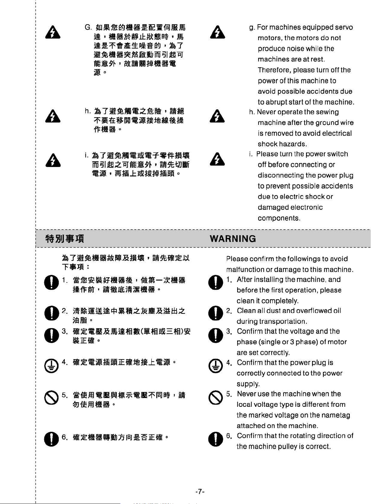
G.
~
.19!
l'f.J
II
ft
:m:
~I
fiiJ
niH~
ii•IIBMB.L!:~D~·~
il!!:1'1t&~lllfil'f.J•1:i7
it~ti~~~~JNihffii
tlit9~
j}o
h.
1:6
1'•tt~~m•~•ma~fltt
'
i!&illltjtlft.
71¥~111-.:Zfe;rt
iJI
ieRJ
' All!
fFflfto
g. For machines
motors, the motors
produce noise while
machines are at rest.
Therefore,
power
avoid
to
h. Never operate the sewi
machine after
is removed
of
possible
abrupt
equipped
do
the
please turn
this machine
accidents
start
of
the
the
ground
to
avoid electrical
servo
not
off
the
to
due
machine.
ng
wire
I
i
M~.mall
i.
1:6
7
~~~Mtl:eX.T-W.f.FHUI
ffii
iJI
JW.:Z
RJtma9~
11~ • ~HIL.I:sxt~~tiBJi
,
tt9t+J.Jif
o
i.
WARNING
shock
Please turn the
off
disconnecting
to
due
damaged
components
hazards.
before
prevent
to
electric
power
connecting
the
power plug
possible
electronic
.
accidents
shock
switch
or
or
1--------------------------------------------------------------------------------------------
~7~~~~•i!&•~M•·a9t•~~
~-Jft:
'l'ftl!it&iltlfttl•
~11=M • ilflUl5l~ltH
j.
~
il
il
it
'fl 5
5m
n6
o
lt~--~~il~ll(Jl~:eX-
MM-i~tlll
o
tl
.:Z
1!k
II&~
ttl
;Z
~)~
&:iEmo
Please confirm the followings
malfunction
or
damage
to
o 1. After installing the machine,
before the first operation, please
clean it completely.
Clean all
during transportation.
Confirm that
phase
are set
Confirm that
dust
the
(single
cor
rectl
the
and overflowed oil
voltage
or
3 phase)
y.
power
to
avoid
this machine.
and
and
the
of
motor
plug
is
{S)
5.
-7-
correctly
supply.
Never
local
the
attached on the mach ine.
Confirm that the rotating direction
the
connected
use
the machine when the
voltage
marked voltage
machine
type is different
pulley
to
the
power
on
the nametag
is correct.
from
of
Page 14

·ti::.·
~
-~~~~~~*•~~m~z*~
am;
I
~5tHf115J.[iH~
flft~f&~i1J3if.iX.:Zlt9~
·---
---
----
---
--
~~
------ -- -
••••
------------------------------------------------~-------------~-~---------------------------A
2.
~~mM~fl~·••~••~~m~o
~•••~~~~-~~~-~a•Bm
••
0
I
J,).~~~
0
~-
----
---·---
---
A Warning:
6.A
--- -- ----
WARNING TAG
1. There is a warning tag attached on the
2.
Before doing any operation
adjustment desc ribed later in this
manual, please turn the power
prevent accidents caused by abrupt
start of the sewing machine.
--------------
sewing machine.
When using the sewing machine, please
follow the instructions
contact the dealer
fuzzy.
- -------
{F
ig.
if
the tag is fallen
-·--·--
1)
of
the tag. Please
or
~
-·--
any
off
- --
off
to
or
---
~
I
I
I
3. Safety protection device (Fig. 2)
Finger protector
-8-
~§ll
~~~H
111/Fig. 1
Goggles
.2/Fig.
2
Page 15

4.~
~7.J'f1Jh1JIRJ
0
(113)
4~
Indicates rotating direction.(Fig.
3)
SAFETY ILLUSTRATION
I
1--------------------------------------------------------------------------------------------
*•~•z~A~~-·~•m~,~§~
jl{1==lf(l9{1=!t~i£
4)
'
-~~JtR.K#iffP
o <II
NEEDLE GUARD
This presser foot protection device is as
10.
shown as the Fig.
operators, this device shall not be
disassembled. (Fig.
For safety of all
4)
~3/Fig
OF
THE
.
3
-----
--------
I
---------
----
-
----
----..-
----
-----------------------------------
! ltjJJIIJM MOVING
'
~~~------~-~~
M*JHI
1.
-~·~m~~~~M-B*R·~~
jj;~J&MilfiiUI
z
ltil
--------
~~~
<1115)
o
-----------~------
-~~
----------
Moving the sewing machine (Fig.5)
1.
To
follow
hold the fromt machine cover body, and
right hand to
move.
2.
Please wear safety shoes while moving.
-9-
114/Fig. 4
..-
---
---
------------
THE
---
move the sewing machine, please
the figure shows. Using left hand
SEWING
----
-----
hold the bottom plate to
MACHINE
--------
--~
---------
---
--
--.
---------
to
Page 16

1115/Fig.
5
·-----------------------------
---
-----------------------------------------------------------~
MIJ.a<Jii:&fil• THE INSTALLATION POSITION I
-------------------------------------------------------------------------------------------- l
1.
~~~-~~-M~~~~,~-~~'
®SM~---~~'~ru~®~-~~
*M~.Hia<J.-TT-tiJiJT~W
o
<1116)
1. Please
near
Radio,
equipments
interference. (Fig. 6)
do
not
install
the
equ
ipments, such as Television,
or
Wireless Telephone .
will experience electronic
the
sewing
Or
machine
these
X
2.
BIHfM~IIl!Ui~.MC.~M~
fiffl~~-• ~fl*iitiXtlfFZ&.
7)
•
tto*
o
<II
2. The wire
socket
this mi
shou
directly
ght
cause malfunction. (Fig. 7)
X
-10-
1116/Fig
ld
insert
. If using
lii7/Fig.
. 6
to
the AC power
the
extension wire,
7
Page 17

Page 18

II
Model
Jill
2. Specification
fl!\!1!!
Standard
700F
IOJfjf.!i!.
High
Stroke
Jiitr'OJIIi!Ji
Max
Stitch
Speed
l!li"rlf:
Noise
Level
~
l1e
Stitch
Length
jlfmf;jjj1
Stroke
11!1J'!Hiifl
Presser
11!1J'!~.:IJ
Presser
~!<.
Feed
{tllJjlf
of
the
needle
Foot
Lift
Foot
Pressure
i'iliffl'
(r'JI±\jlffRjlij)
Dog
Height
plate)
Needle
bar
(over
for
Use
the
needle
7500
spm
80?tft.DXf
under
80dB
3mm 4mm
24.7mm
5mm
5kg
under
l.Omm
DCX27
7500spm
82M'rf
82
26.6mm
5.5mm
dB
~J'l,{$t'J/)~
Feed
Dog
Transmission
~J'!~1i:ffl'
Teeth
Width
of
the
Feed
Dog
~§w.l~ll€l!i
Stitch
Adjusting
11!1Jl.~jli[
Presser
:tJUi!lr:IJ~
Oil
@)~/)~
Oil
!till
Oil
Foot
Filling
Return
ill!
for
Use
Device
Device
Solution
iii{,·~
Eccentric,
Button
'lfll~~-limw.J~~
Spring
~~m~~11~-~ft-~~~~~~t'J~~
Oil
tank
storage
Type,
type.
Automatic
.
J!!!f!j!
Connecting
1.8mm
~Ww.l~
Adjustment
Knob
Adjuslment
oil
capillary
Rod
supply
action.
by
Type
felt,
cotton
thread
iiiiMll'ii
<!<2/Table
jJE-fMJ!ll
Provide
2
Specific
Ecoentric
Pump
ill!(MOBIL#
Oil
(MOBIL
10)
#10)
-12-
Page 19

I
'--------------------------
---
------------------
- --
---------------------------------------
NAMES
OF
MAJOR PARTS
---·
'------------------------- -------------------------------------------------------------------
G)
G)
~'~tli~
Lifting lever
<2)
1,~
@~tUft
@ji~
@ )W'I'
@~·
® Presser
@ Control
@Thread
@Oil
@Pulley
gauge window
(Hand Wheel
(j)
foot
box
stand
-13-
118/Fig . 8
Page 20

--------------------------------------------------------------------------------------------~
I
INSTALLATION
0
A
~-CAUTION
~-~~-~~&~A··~~-~-o
Machine installati
on
should only be carried out by a qualified technician.
~~R·-~B•aw•A~~fi··~·o
Contact your dealer
to be done.
llj}JM.4821JT.
The sewing machine weighs 48kg. The installation should be carried out by two
more people.
~~-~~~,"~-~~-~~~-~~tiOO
Do
not connect the power cord until installation is complete. The machine may
operate if the
•~•Bm~wg~~m•~~ft~~o·~~~~~~~~•~•••-m~
JhWif~{lo
Use both hands to hold the machine head when tilting it back
treadle
or
a qualifi
~Vii1'F~~B:IRiiAJ.1J:*~.SX
is
depressed by mistake, which could result
ed
electrici
an
for any electrical work that may need
o
•.
M~Wti~*WB~~o
in
injury.
or
returning it to its
or
original position. If only using one hand, the weight
too heavy to
1.
•*•m~•~•••&•~M~•m~
hold, and may cause human physical injuries.
1. Install the rubber cushion and the rest
~~~··8~-~--~~~0~~
~~m~q,M~ti~oooo•oo~~-~
100
mm'
2.
•~w~•~~-~~~~~·~Aam
~,RIJ·~~-
4.
~-~~~-~~~~-~~·m~~•
SIJIJ.:J.m~li~~-~M10
ii: o
~~5.7eit.RIJR~5
o
m11MWII~·ilil·ft«~3
mm
o
mm~SIIJ.~
o
2.
3.
4.
of
the machine head may be
board in sequence as the attached
cut-out drawing and the part lists.
of the semi-submerged type
the distance from the surface of the
needle plate to the surface of the table is
installation,
table
In
case
100 mm, whereas the fully-submerged
installation is only 5 mm.
type
Install the pedal of clutch motor on the left
side, and the pedal
the right side .
Install the waste chute and the thread
stand as the part
The turning direction
clockwise . In addition, the best tension
that the belt can be pressed inward about
10
mm by a finger. Please refer to Table 3
of
presser foot lift on
lists show.
of
the motor is
is
to see the interaction of the
the sewing speed.
-14 -
belt pulley and
Page 21

-~
Machine
..
~
(S.P.M)
60Hz
~itff$if;fmr~
Motor
pulley Diameter(rnrn)
50Hz
6,000
6,500
7,000
7,500
! - - ----
I
I
i
I
1
-------------
----
-----
-----
----
---
- - - ---------
-----
fJHIIIItJOM.:ii:
-~-
~-~-~
--
--------
tJHIBttii:VJJNJf.laJ~Wla91mii£WJ~
Jf.liEEM:II:iSil./120%a9il!.l•tt'
ffi~715dl
' ::tii • .¥Aitiil11 o engagement. After four weeks, please
------
--~-
'it
zfljtJ:. maximum speed
95
105
110 135
120 145
~3/Table
-------
3
- - - -
HOW
---
---------
-----
TO OPERATE
MACHINE
----------~~--~ ~
Pleaseoperatethismachinein80%ofthe
operate under the maximum speed
~-------------------------
1
i
BHiaZ~AiilJ!.
'----------------------
-
----
---
------------------
- --
--------------
replacing
---
------------------------------------------
LUBRICATION AND DRAINAGE
----------------------
the new lubrication oil.
115
125
- - - -
------
----
-------
THE
-------------
in
the first tour weeks for
-
------------
NEW
-
~-
until
-----
------------
do
not
-------------
- - .
1. JJ)i5W.:Z.$1A.(II9)
(1)
~•**<D~~m
~il~jf5dla2i1Jf.IMOBIL#10~
AGIP#32W~'I'.:Z.tl5di1JDA.,
m~~m•~~J:.~z~~~~~•
iii.SUIM<D
1. Fill the lubrication oil (Fig.
,
J.j~t&$6~1ifirwzm
(1)
fl@$dl.
o
9)
Remove the screw
the attached
lubricating
oil,
G),
and fill it with
ultra high speed
or
choose MOBIL#1 0
or AGIP#32 or equivalent. Tighten the
screw
CD
after the
oillivel
indicator
locates between the two marking
lines.
-15-
1119/Fig.
9
Page 22

(2)
r»UlUIHIMf!~I*fiffl
• ,
J:.liltiitW1Jil5m~;~
2.
Jljf)W;ZJ!lt(ll1
(1)
HfiiMCDtitRMEM
~HHiiflMIHR
(2)
1\i!E~*tiB.:ZW$
fllm£1J)J!1t1Ff5W···~-Imii~
)!~-;~
a~
'
Mt±ti
o
0)
•
'fil!5WM~a<J5m~
o
• tiMMMHiffl
0
(2) Please lubricate the needle bar and
the upper
operating a new machi
idling
2. Drainage and refill the oil (Fig. 1
(1) Loosen the screw
oil inside the oil tank. Then, tighten the
screw
(2)
In
order to extend the term of usage,
please replace the oil after the first
four week, and then
four months.
looper shaft before starting
ne
or a long
machine.
0)
CD
and drain all the
CD
again.
replace it every
~
111
0/Fi
g.
10
3.
3.
ttz~w>m
ff!m5m
:
~5m
Needle cooling lubrication oil: SILICON
OIL.
THREADING
------------------------------ ------------- --------- --------------- ---------------- --------
~~-~M~~~~~~-~~~9-·U
~.:Z!I.w.Ji31lelli.,
0
lift
(11111)
~tt&$8~3Jli!l~
Follow the procedures shown in (Fig
threading. Wrong threading may cause
thread breaking,
unexpected sewing. (Fig.
§89*111
st
itch skipping, puckering or
11)
For seam type 516 only
9)
for
I
-1
-16-
Page 23

I
'--------------------------
---
------------------
- --
---------------------------------------
---·
ADJUST THREAD TENSION
'------------------------- -------------------------------------------------------------------
~-~~~~m••~~~••,••,•
~~&§~KM~z~~~-~~z~M
1.
~~ez~••~<•12)
(1)
M--lt&
<D
~tGWJi~MEXtrJI~
o
£ji
The thread tension
properly according to the kinds and the
thickness of the materials, stitch length , and
seam width , etc.
case by case individually.
1.
Thread tension adjusting nuts (Fig. 12)
{1)
The first adjusting nut
double chain stitch threads
aver-lock needle thread.
(2)
The second adjusting nut
the seam lock needle thread.
(3)
The third adjusting
upper looper thread.
(4)
The fourth adjusting
the lower
(5)
The fifth adjusting
double chain looper thread.
should be adjusted
In addition, adjust the nuts
<D
controls
or
the left
(2)
controls
nut@
looper thread.
nut@
controls the
nut@
controls
controls the
2.
2.
at•~••~<ll13)
(1)
HM-8"1J:ft504'
~:ft "'F~ ' MSJJ~503&505Ht
G)'(2)3~ftJ:~o
(2) ( +
)~~11110~·1&··
-~~M1JiM•o
514Hi '
Mf<D'
'
(-
)~~
®3
' ~
-17-
Needle thread control (Fig. 13)
(1)
(2)
IJi12/Fig. 12
When the sewing type
514, move the nut
lowest point. When the sewing type is
503 or 505, move the nut
the highest point.
The (
+)
direction indicates
the needle thread length,
to decrease the needle thread
<D
and
is
set to 504 or
(2)
to the
<D
and®
to
increase
(-)
means
length.
to
Page 24

3.
tt:
I
1;J
tt!!!'*illliMI14)
c1J
:ttli~nl'\11.512.
··~®M~~~~~~mi·~Ii
~n'i\:11.503,
ftm:•
(2)
~:;E~!If;j&@~~:
All
81\:#l~lll
CJ.';:M~n'i\:512
(3)
~:;Eill!lf;!&@~~:
DJ.';
Ell;:
C +
l:1JiOJ11.1i~iiUli~
•
114®M~Illi!!~'JUim'l'
:
JB
n flllllllll
:
1B
ftO
fllllilil
#I~
lll
!ILI::1;Jtt~~r.tc
504,
*i
505MJ:1;Jtt~~
•
JiLZftl)ilid>
•
•
I!!J13/Fig.13
3'
Looper thread control (Fig. 14)
(1) When the sewing type is 512, and
upper
adjust d)
dotted line.
503,504,
the
and®
continuous line.
(2) Adjust fixed thread
followings:
Point
Point
Point
(3) Adjust fixed thread
followings:
Point
PointE: for blind hemming
NOTE:
The
direction(+)
sewing seam, and
less thread
looper
lowest position,
at the position as the
A:
8:
C:
D:
is
on
the
left
and®
or
for
for blind hemming.
for sewing type 512.
for
in
sewing seam.
at the position as the
When
505,
nylon
stretchy thread.
the sewing type
and upper looper
set
the
guide@
stretchy thread.
guide@
is
for
more
thread
the(-}
direction
est
side,
take-up
as the
as the
in
is
is
is
CD
for
at
-18-
lii14/Fig. 14
Page 25

I
'--------------------------
I
---
------------------
- --
---------------------------------------
---·
· llatn5t REPLACE THE NEEDLE
'------------------------- -------------------------------------------------------------------
fflf!DCX27eila];i~;Zti
1.
2.
tifi!ml!II**CD~Im'"fMo
3.
~~tiM¥tiRa~•·~~tiz~~oo
JRJ~2o
4.
iJ)E!IIMCD
0
o
(.15)
Please use the needle DCX27 or the
1.
equivalents. (Fig. 15)
CD
Loosen the screw
2.
needle.
Insert the new needle till reaching the end,
3.
as well as the long groove faces your side.
4.
Tighten the screw
and take off the
CD
.
1
1115/Fig. 15
~-------------------------------------------------------------------------------------------·
I ttBelll! ADJUST
l_----
-------------
~mMM~~M·~ti~z~la.I~R~oM
•m'"'F~BCD~Mtim~MffO*~'M.
111m
1f¥nt
~
Pfi
16 ' fi4)
m z
----
tt
~ -~ -~-~
BE
fi
nt
-----
rm
Jlt
tt&
-------
o c •
--~ ~
~--------- ---
The stitch
fabrics , the differential rat io, or other factors .
Keep pressing the button
pulley till the button is locked. Then, release
the button after reaching the desired stitch
length. (Fig. 16, Table
THE
length is adjusted according to the
STITCH LENGTH
-------
~-----
CD
4)
----
and turn the
~ ~
~-
------
-19-
(116/Fig. 16
Page 26

Max
Dif
ratio
Machine
type
Pulley scale
1 2 3 4 5 6 7
Seaming
Shirring
Serging
Special
- - - - - -----
1:1.3
----
1:2
1:3
1:4
-----
-- -- - - - - - - -------
•11Jttll•
~~~~tt±~A~~~~~~AzM~n
tr.J
J:t~J
0
1.
~±~~Az~b~*~~~~~A-~
~~·M•fl••~~~·&zM~fi
2.
•~n$~~--~~•ti•~®m~•
n~~~-fl~fi·&zM~~··~~
MlillE!I!I'*CD o
(.17)
1
0.7
1.6
0.6
~4/Table4
-·-
-·-- - - - - - - - -
o
1.
5 2
1
2.3
0.9
-----
1.4
3
.1
1.2
-------
ADJUST THE DIFFERENTIAL
2.5
1.7
3.9
1.5 1.8
--
- - - - -
----
3
2
4.7
3.5 3.8
2.3
5.4
2.1
·--·--
- - - - - -- - - - - - ---l
2.5
5.9
-
FEED
RATIO :
The
differential
movements
di
fferent
1. When
2. Loosen
ial
the
bi
gger
fabric
to
clockwise for
reverse
is
the
contrary.
feed
between
feed
dog.
movement
than di
direction
fferential
stretched
screw
stretching
ratio is
<D
and
for
main
feed
of
main
feed
in
sewing
turn
shrinking
the
the
the
rat
io
of
dog
and
feed
dog,
the
and
shirked
screw®
fabric,
the
dog
is
in
and
fabric,
in
i
~:
-~-~®2~~~~tt~~~·~~
IIJJ:t~1:
R1"0011J~~~~1:
1 f
~~~ISilEtt~JIJ2j.~J:Pi
o. 1 o
<e::~Jfi5)
and
then tighten
NOTE:
When
I
set
ratio
it
1:0. 7. (see Table 5)
at
can
the
the
is
1 :1,
make
surface
scale
and
the
the
of
2 ,
the
if it is
fabric
screw
adjusting
<D
differential
set
over
stretch
. (Fig. 17)
level@
feed
the
scale
to
the
ratio
be
2,
-20-
II17/Fig.17
Page 27

Scale
1:1.3
1
-
2
1:0.7
1:
3
0.9
4
1:1.1
5
1:1.3
Diff
ere
ntial
Feed
ratio
1:3
1:2
1:
4
I - - - - - - - - - - - - - - - - - - - - - - - - - - -
,,
: afFIIiJftlaij LIGHTENING
I ENVIRONMENT
~
~ ~ ~ ~
-~
-- -- ---
--~ ~ ~ ~--
...-
- - - - - - - -
--
mm-••~•~·~~~m~=I•m•
~~~~-~~a~mtt~-~~~*~ti
~M-·M·MttM·~~-;~~--~
ft*·A~--~~~ft~M·'·M~-
····~~~~~···~-~~-~
ft~~~-M~~~~~~
18(fi~
o
·~-~~-
1:0.7
1:1
1:1.1
~5/Table5
---
~
-
--
- --- - ------ - - - - ---- --- - - - - - - - - - - - - - - - - - - - - - - - ------- - - - - -
1:1
1:
1.5
1:1.6
1:1.4 1:1.7
1:2 1:2 1:3
1:2.3
OF
-- ----
~
---~
---------
Provide a warning
unit or sewing system must always be
unplugged from the local
sewing area before relamping, the marking
maximum rated
discernible while the lamp
indicated on
shown on Fig. 18.
---
input
or
near the
-
~~
that
1:2
1:2.3
1
:3.3
THE OPERATION
~
~ --~ ------~-~
an industrial sewing
lighting
of a lamp shall be easily
Is being replaced
lamp
of
the
socket as
of
~
,------
~:k51rt~·
Maximum····
~
'J'
51rt
Minimum·····
--~
---------------------------------------------------------------------------------
····51
~-
• • · · 430
·
51
430 Lum
ii18/Fig
i flfF:f.f-j: CONDITIONS
1.
MS~71W1fffl~~-~~
2.
~illfH-3$rJ.Jft~~>1M*ll
3.
7M3W~*IMZMJ.Io
4.
71WM~MH;Zji{1=1J~
5.
tl{1=~~1i~*lfliAA8.tlH
o
o
o
o
Read and understand well the content
1.
this instruct ion book.
Know the functions
2.
understand the notices.
Truely realize the meanings
3.
tags
.
Realize and be familiar with
4.
operate this machine.
Operators have to keep well menta l
5.
status.
o
mta~
0 Lum
)iff
a~
. 18
OF
ALL OPERATORS
of
major parts and
of
all warning
how
to
·
of
-21-
Page 28

6. Operators shall wear appropiate and
proper working suits.
7.
Develop the familiarity of how to operate
the machine if needed.
ii.
____________________________________________________________________________________________
MAINTENANCE :
I
j
~
)I~JH'l=~iW
"'/......_1!-\_.Turn
!:::\
\Ysliea~
!:::\
\Y
off
the power switch before carrying out cleaning. The machi
treadle is pressed incautiousl
1J[]•5t)m~Jt5fblli
o
Be sure to wear protective
grease so that they
be resulted.
J'J5tt5m~j()dJ1"~ftm
Furthermore,
diarrhea. Keep the oil away of the reach
M~tl~~~~•m~·a~W-=Filfi~f'Fo
Use both hands
&position.
I
fi+JJifj
do
not
to
A
0
••
I
~t!IZ-12~1i!IIUI2~-¥~
do
drink
hold the machine head when tilting
-~Mielb~lllfti
y,
which could result
gogg
les and gloves when handling the lubricating oil and
not get into your eyes or onto your skin, otherwise inflammation can
,
aftrJ~ftslmlftn±~Diil,
or
eat the oil nor the grease for they can cause vomiting and
s±acAuTION
I
fljj]tlltJf'F~·BA.A~11
in
injury.
I
J.)Jn~715mil.AIUI~~5o«szaJ:
~5dLfiitt'J\~*1'¥1Ja9iii!n
of
children.
or
°
ne
may operate if the
returning it to its original
, ~
o
~
-~-~Jii~~-~-a9··~-~--~-~-fi~~o
If
only using one hand
pping
sli
and you may get hurt.
to
«1i•»
1.
~liH'A
2.
~~~•M®m~·~•m~~~®
move the machine, the weight of the machine head may cause
For keeping the machine quality and
lengthening the usage term of this sewing
In
and lints on
o
machine, please maintain it everyday.
addition, before first use after a long idling
ow
time, please foll
maintain.
(CLEANING)
1. Raise the presser foot.
2.
Remove the two
remove the needle
3.
Use a soft brush
the feed
4.
Install the need Ia
dog
the following steps to
screws®.
plate®.
to
teeth@
plate®
clean
. (Fig. 19)
and then
dust
after cleaning.
-22-
Page 29

1119/Fig. 19
-f*llfi!J~
Maintenance Cycle
1.
~~~JJt
1. Clean the lint
2.
mx.
Daily
~
Weekly 2. Keep the operational panel clean
4!=.
00}3
Quarterly
1i~
Annually
ttit~-~
2. Check
should
3.
~-3rui1'F
3. Keep the machine and the operation table clean.
1.
~
-
Keep
l.
2.
~1J
3.
*:E:11${
3. Check
1.
J!~ftj?g;Z_~Jm~
1.
Change the liquid oil inside the oil
1.
*
~
1. Check the transmission belt to see
.r.
z.~~
on
the feed dog.
~l[
~~zlfltmrm
if
there has enough liquid oil inside the oil pan. (The amount
be
between
~;;.·
the
power cords looking clean and neat.
1'F
OO~~
~
{lf:~:S~JM!J!G;frlEif{
if
the power parts
ltl&:~
the
t:i'
~~
:a!f
(Periodical Maintenance Items))
Maintenance
red
up
and
M~
is
loosening
z.~~m
f*.
JJ!
o
<~
down paint
ii
~
or
pan
if
it
§
Items
:lt
:ff~flz
mark
still
at
the right position
is
weariful
or
(Tab
.r.
..
-r~~~~c!1f
of
the oil level gauge.)
damaged
le
6)
OO
)
~6/Table6
TROUBLESHOOTING
A
A r±ilrrt&llt!HJilP.JzJFJ ,
~
tl*lbfF
Before processing the troubleshooting, please turn
the electronic cord. Otherwise, if touching the start switch incautiously, the sewing
machine
,
~-B.A.&1i\ti
will function and will probably cause injuries happened o operators.
D$tiiiJJ•J:t~tiw•ili
o
~-CAUTION
-23-
,
6ftiJ~lHlM~NI1JJmlll
off
the power switch and
unp
,
aM.J
lug
Page 30

No.
ffi.~
Problem
~~.&ilffl!'il1!
Exam and Adjustment
The
Skipping
Stitch
ofNeedle Thread
·!lt~~.:IJ
The
:lfoi"fll!*)j!G~/
tension
of
the
needle
J
\?
thread
is
too
loose
or
to
tight?
@ilfflJJ!!!f!ltU.:!Jo
Adjust
Choose
@~J!l!C-El';;'JJ:lEII¥J:$!ltlJ!!*il~ljl1li!ijo
Select
••
Bad
@~~l!i!lfo
Change a new
el!i!ltlJ!!tr./;;JW*iiffiZillH11lll~~?
Any clearance between
the
needle
the wrong needle?
the
needle and thread number match the fabrics
!it
1'
Jl!.?
needle?
thread
needle
tension
the
needle
and
the
top
of
the
left looper?
@IDIJ'I'Iftr.1;JW*!lffii~lli!ltZilll±O
Adjust
needle
e~.:IJIDI!'!I!f/J~'liHmfJ'Ill?
The
the
to
small
distance
be
±0
spring
from
of
tension
the
top
adjustment
of
the
left
does
looper
not
to
the
function?
@(1)/Ni!!l~Hmf'F!lJ~
tl'A:I"<J!~~;Jitg:~~
(I)
If
the
small
spring
more
tightened.
happen
(2)~ilffl!'ll!:fi;J!t~~Wi
(2)
If
adjusting
e!lt~i¥1~.1J:ot~?
The
@(l)tf'l!lt~~.:IJ
(l)Loose
there
tension
the
if
pull
the
is
any
groove
plate.
of
the
~ltilffll~
tension
does
(Note)
spring
please
needle
of
the
·
~'l1¥!Jl'tL~~!!\'i
0
not
function,
The
brokeo
too
tight.
'
Jl~:11i~~IDI!'II!:fi
existing
change a new
thread
on
is
0
needle
thread
the
one.
too
tight?
thread
pull
tension
o
(~:@:)
it
to
be
will
properly.
0
-24-
Page 31

No.
:fl!il<
Problem
*
Exam
1!!:.&
iiliiJ~
and Ad'ustment
2.
3.
M~ll9l'J'Wo:fl!~
The Skipping Stitch
;b1;)!1f~ll9l'iWo
The Skipping Stitch
Looper
Thread
of
Needle Thread
of
the
Right
(2)11'l!it~ll9W!I(A)ii'iiJ>IIHEJii!:i'iiif:!L~
~m'(B)fl9!it~l!ll:t±:l:i:~:P
(2)Adjust
position,
thread
(3)1!'l~(C)ti:@H!'b
(3)Lean
amount
eki
The space between the
wide?
@;b1;)MfE.Jkii.!!!.l&lf!i
l!l::flllE:\l!Jl<JtT1;JM
fl
When
distance
the
line
(A)
of
the
so
that
the
release
from
thread
hooking
•
the
line
(C)
to
left a little
of
the
1;1~
r
W:!l<
looper
~
r
1191111
thread.
'jjl::.t::*:?
right
'
:ID.!IL!itil91111~&:·~.lmm
• <ffol!:fl.!it •
fll1'H~1!1!>ilil'~ll9:fi
the
tight
to
the
looper
needle
tum
has
•
needle
amount
will
Wti.1.J01;JMil9tll!t.61t±:l:l:
to
looper and needle is too
1;)~
l
tight
and
to
be
0.1
•
l!l::lilt~ll91;)
thread
of
to
the
decrease.
increase
~M
backward,
mm,
which
the
highest
needle
the
release
•
J!i!fl
the
is
•
•
15
using
J'J
4
ti:1;JM~Il9l'J'Wo
The
Skipping
Stitch
of
Left Looper
the
correct
each
thin
fabrics,
e!ll'liltlf!i
The
distance
when
©>rn~ki1;J~~~il9ti:ki&~~.&ki1;J!ifmLT~
~&~z~~~~·r~ii'iil~tr1;JliltJ¥J~~~·
1'Eki1;Jlilt
Because
right
position
of
the
the
descending
e;~e:t11;Jliltxxlf!i
The
right looper dido'!
while they
right
looper.
type,
such
as
are
included)
·
:t11;JM-W:6:liltll9r.ll!il:7<:?
is
too
using 2 needles?
T~lf!i
the
correlationship
looper
while
of
the
looper.
right
When
amount
(The
single
need, 2 needles,
wide
between
•r-f:6:liltllUkililtll9TMHJ~:P
of
assembling
looper
the
seat,
right
from
•
:t11;Jlilt
hook
are
crossing
each
appropriate
the
right
tight
looper
materials,
and
left
for
and
needle
•
the
left/right
and
the
adjust
looper
left
::flt1;J¥Uti:1;J!if~?
other?
descends,
needle
the
left looper thread
position
up/down
the
movement
to
right
of
moving
d=ase
needle.
the
path
@~¥1f:6:1;Jlilt
lil'ililllltf:\~7
Change
is
looper
the
new
worn. When fix and replace, the protrusion
top
shall not be
-25-
•
(;6:1;)lilf'cRftffilltffjl
j;Jft(}!jlf)
left
looper.
worn.
•
(The
·
'!!~IEII;f
top
of
the
•
::ft<lolt'l
left looper
fo
the
Page 32

No.
l3i\11<
Problem
~'!'t:&iil!l~
Exam and Adjustment
5
The Skipping Stitch
!tit
Needle
Broken
l
I I
j
/ /
-
.
.
.
/I
of
Left Looper The wear
@~1'1f1;)~!liG!IIilll:O~<Rf!ffiii'.ilVoR
·-~1¥:1~~=1'~?
@:tE:ffl:lSfNt~~:fLI¥Jliilii>!II"J
e.JI!!""I¥l""l!H
@';(~~~~~ffl:iji'j}f-~~.jlj!~~~~$*o
.
e¥&:ffl®l¥1'9:~lili1li.T~?
@illf~j!g:fflJ!iil'Jr!lJ!l<~
of
the right looper top?
Change a new
Choose the wrong needle?
Use
thick
pinhole
looper
needle
occurred
or
within
on
the
use
the
fabric.
.lit?
Bad
assembling
During
central
Wrong
.JI!!~ItiJ
assembly,
point
assembling
of
the
presser
make
sure
of
the
presser
height
0.8mm-lmm'
o
the
range
the
foot.
of
the
0
oil
stone
to
wear
the
top.
·
{]I!#Jf.l.!~~I¥J:iji'J}f-
that
there
will
be
foot?
needle
feeding
can
insert
teeth?
[OJ~~~il'J
no
to
o
the
The
Top
of
the Needle Damaged
~
\ i
Adjust
to 1 mm.
pressure.
the
height
Meanwhile,
of
the
keep
feeding
the
teeth
to
be
appropriate
around
presser
0.8
foot
mn
-~~"''ll<?
Bad
threading?
@~~:fUJ!iiii'i~ll'>%:/JofJ~lll!f&
If
there
is
any
connecting
dealt
first.
Then,
rethreading.
The
right
looper
position?
©J:iji'j}f-:t£~~~~~~·m~m~~-~~oo~
~·~~<Rf!ffii~"''~~~~~j}f-·~~iil!l~-~~
1l1!liG:t11;)J}f-I¥Jlli!IIJ0:~·
When
the
push
the
needle
the
top of
and
needle
the
moves
forwards a little
needle
part
the
needle
close
touches
of
to
the
•
ii-l'li~*&
the
thread,
have
wrong
the
upper
by
finger.
right
looper
it
height
dead
See
or
•
needs
point,
whether
not.
Then
to
be
adjust
position
-26-
the
height
of
the
of
right
the
looper.
needle
position
or
the
moving
Page 33

No.
J31.~
Problem
jt~J;liif;J~
Exam
an<f
Adjustment
6.
7
-~J-ij<iiffii~tll
The
Top
of
the Needle Damaged
•m~
©tll\
·~t!li'ti.'~li!PI'W?
©re~t!liNWi'ti.'~~A$*(1(}1lll~::k~~.
-~~il'J~.fLl9.:flft?
Broken
Stitch
Tbread
and
Rough/Uneven
©!llli'J>~.fL/!flliiM7'6
Jt:t:~lif'?
The
ejector
]lij(I(JJ<i~
lli'f
•
lltJ!ttlli~l1iftllll
@lll'i'::k~
The
ejector
the
top
needle.
needle
Incorrect
When
so
that
The
thread
plate
!t
£'{(i:(Etc
0.2mm
plate
of
the
left
The
distance
is
about
0.2
needle
assembling
the
space
hole
plate
of
is
too
close?
•
inside
looper
between
mm.
assembling
the
needle
of
part A can
the
thread
1;)~(1(J~Jlffi!¥1J~l!L~
·
mroom~
must
leave
reaches
Jtllifl!l~(I(Jill.l'j£,
from
the
the
right
side
the
front
ejector
position?
plate.
pull
it
forwards
be
larger.
stand
did
not
polish?
·
Use
emery
cloth
to
polish
the
surroundings
needle
of
plate
of
the
:.bii!Ullff
before
the
to
the
a little
thread
,,
hole.
//
·~(I(J~~r,;r~?
'F
/
Choose
©:11!~(1(]~
Change a better
·~(I(J~:!:Jml!'i'!!f?
Cannot
©~~ft:.b1;J~(I(J~T-~~·~~~~~~~ili
'Jl.'l±:lil:¥1J:flllil(I(J*'l!'i!!ft
Please
should
needle,
noticed.
A.N~~*'l!~ft1;J~*'l!~~:.b1;J~*'l!~~·
A.
B.N~ft~~~~:.b~~*'l!~~~~*'llili~~·
B.
the
wrong
thread?
'
~-W:'3EJ
thread
adjust
to
the
be
noted
that
not
be
too
loose.
the
related
Pull
the
needle
loose~the
Poll
the
left
changes
thread
right
looper
to
balance
best
thread
•
the
threads
When
tightly--+the
looper is
thread
.
the
tension?
of
the
adjust
of
the
threads
tighter
tightly-+the
threads.
left/right
the
position
are
left
looper
right
looper
of
needed
is
looper
one
to
is
be
looser--+the
C.
N~:.b1;)~f~~ft1;J~f*'lld~~l*'lld
C.
Poll
the
right
thread
-27-
is
looser-+the
needle
looper
thread
thread
needle
is
looser,
too.
tightly--+the
thread
is
left
looser
•
looper
Page 34

No.
m~
Problem
~J'fliUJll~
Exam and Adjustment
7
lfi*&W!iillil"
Broken
Stitch
8
The Thread
Doing Chainstitch
"Hll
Thread
does
and
Rough/Uneven
not
Come
Out
When
e1f!IJJ.~'i!il'illl~T
Incorrect
@im!~1f!IJ'-5!i'l'i'E!leil"ffi'Z!ffll¥.rf!f:!SI
Adjust
adjustment
the
presser
.l.i!.?
of
foot
flexibility
the
presser
to
foot
fit
spring?
the
fabric.
eW7JMtll?
The
knife
is
worn?
@l!ftU7JD~:l!!lfl1~61t
Sharpening
the
knife
o
or
changing a new
one.
e£1!1tt*I!Bil"?
The
differential
ratio
not
match?
@iiiJJfi!Bi\":ffl:jSfi¥.J£11JJ21ifJfo
Adjust
The
@W!J~'I!I"R<J~lilili/Hir
Adjust
the
cam
the
dillerential
of
the
chainstitch
cam
to
feeding
looper
o
an
appropriate
to
match
is
position.
the
feeding
not
appropriate?
fabric.
9.
Cannot Separate
Thread
the
Thin
and
Thick
·t.'l!~l*T
Thread
@(I
)1\IIJ'!I!f~~5ilil3!'
(1
)adjust
(2)!JmJ\';~~
(2)polishing
•1fll*1&5!11~3('i.H
The
©JmJi1iiml~l!i!~~lfl1~
J.i!.?
tension
the
presser
device
spring
or
changing a new
does
strength
J.i!.?
foot
rear
spring
not
work
well?
one
did
not
assemble
•
ll!'1fll*mlli§~o
well?
·
il!zlill:;~t~
:fJo
Readjust
presser
The
@il'fi!.:F~~ll!I:B-il!'ii!Jl!ll3lU~llfiL.t
Clean
eJ!ii.G,~lilili1'1!$U5!11'A'li!'il~T'M?
the
foot
can
eccentric
the
stuck
spring
act
is
rusty?
part
or
change a new
smoothly
so
the
and
the
oil
test
o
can
one
to
its
pressure.
reach
make
the
cam.
sure
the
Inappropriate
adjustment
spring?
@W!J~'!Oiz~i31'
Adjust
-28-
to
the
•
proper
{BTllJ~
tension,
of
the
eccentric
but
o
should
cam
not
control
be
too
loose.
Page 35

No.
m:l!<
Problem
~
'l't
liUIIJ'!i!:
Exam and Adjustment
9.
10.
f.llRIE~Offl~:fr
Cannot
Separate
the
Thin
and
Thick
Thread
fr!'fl '
Loud
ill~'
Noise,
Strange
Noise
·~ltifilll!ilflll'iGt'iZ.71!-J}lll'iGt'i"F'i'?
Inappropriate match with
stopper
@(l)!l<JE
(!)Correct
(2)]!!jjr!
cam?
KP09DJ[)l't~ii'J'KP06FJ[)l't
the
width ofKP09D
KP06F
short.
KP09D/KP06F •
the
slide block of the
or
polish
•
the
width of
(2)ChangeKF09D/KP06F
.,
i:.'lill!!!l!l!Jtl:\'l'?
The
main
shaft
is
loose
and
has
noise?
@ll'l:k'C.'J::fi<J~Jt'Z.Jill!ii~1l!f~
Clean
lhe
shaft
and
copper
readjust.
glue
from
lhe
•
mmii\111'11!:
copper
cover
of
•
lhe
main
eJJian:tci1>11>JI'l?
Noise
of
lhe
pump
(scratchy?)
@!lim~:JJoll!iJJii!ll®4iill
Use
lhe
and
fixture
keep
lhe
to
pump
add
pressure
running
•
~
on
3-5
minutes.
3-5
:B-Bll~llJ
lhe
gear
of
lhe
•
pump,
-~~~~!liP.
The
needle
@ l!!!fUr
Change a new
so
that
ei!.!!~
J::ti)i1MIIll!Wlz
The
fixed hook of
clearance
@(l)~**:IJD~
(!)Add glue onto
)lllf
11:11
( 2
(2)Polish
(3)]!!jjr!~fo
(3)Change a
bar
is
loosening?
r11.
~llliS
the
clearance is smaller.
is
*
the
;!tl:~tfll
one
or
to
lill
!E
the
connecting
loosening
the
screw
l,liG
{llj fil
goove
new
width
one.
e_L:r7JmftHW?
Incoorect position
@i\111
'!IH7J
r 7J
Adjust the angles of
%J
!t
of
the
·
the
1!ii
~z
llll!Wl!!!!
polish
or
upper
the
contacting
1;1~111
•
OOt~?
rod
controlling the
clashing?
wider
upper
or
chamfer
and
the lower knife?
and
the
'J' .
surf
lower knife.
act
-29-
Page 36

No.
II.
:Of'
fjgft
The
Oil Does
"-ll.~
Problem
Not
Splash
~
i!f
liUill'l!£
Exam and Adjustment
e'lltnHl±iilll?
The
oil
docs
not
come
out
from
the
pump?
@(l).!li;~li{l!{i'I~
12. JJ!t:'f''flj
The
Knife
Is
Not
\
Sharp
\\
. "
\
\\
(2)Change a new
(3)m~~B9*~~~1\Ii
(3)Clean
(4)/ll~t.l!mJmillll!ll
(4)Use
the
the
dirt
iron
filter
or
change a new
wire
to
clean
one
thmugh
the
oil
path.
ew;J:'f''fiJ?
The
knife
is
not
sharp?
@(I
:JI'flj~]!!~1\fi
(l)Polishtior
(2){i(1EJ:
(2)Correct
knife
(3l!I!1\111Elifl!~~(~;l;l;jj';Wlf!/!~~)
TJJ!t~fii.l@'
the
set
(3)Reassemble it correctly
and
adjust
ill!<2/Chart 2
&'o
change a new
angle
based
of
on
the
the
one
upper
(to
assemble
norm)
and
lower
-30-
Page 37

I
~--------------------------
I
:
••.
'--------------------------------------------------------------------------------------------
---
------------------------------------------------------------
TABLE CUT-OUT
---·
1
A
I
·-
1
~I
crrrmr:::
Bg_
~~
._____--------~~~
I I
I. I.
~§
II
I.IJ.II..
~
~~~~
II
I I
1 m
l..l·
~
j L
~
~~
~
ft!l
1Q2Q
~~
~
A-AHli
.20/Fig
. 20
-31-
Page 38

-------------------------------------------
-
------------------------------------------------1
DEMOLITION PROCEDURE
I
I
I
1.
•~w•••~~w~•~,fi-®&*
m~Q~~~,~q~•••~~~~•
.0
2.
~~~~--~#Q~~m~~~•*•
~M:
(1)
Ji.lf~IIJf'
JIW,#o
•wwf¢:
(2)
(3)
Ma*ffl
}:to
~)~~:··~·'·'·~~-~'
ltf~~Hi~JI
3.
~~n~~~~~•RI~~-~~~~~
~~~m~MM~RI~oom~~•~~~
~MfB1f.!jo
RJfltl*ie'IJ~HlHIIP.lG~F~
m111,
:
:S~
!!fa,ijftAtf
'~ff/RJfEPtifiDI
o
o
When the machine needs to
1.
and
demolished, certain
be observed
and
public
ALL machine componenets must
2.
divided
followings:
(1) All sheathes, flexible hosing and
plastic
(2) Electricity components: switches, or
lighting components.
(3) Insulation materials: rock wool,
flexible rubber strips.
(4) Metals: ferrous metals, copper,
bronze and brass, various.
In
this
3.
correctly, recycled,
use or
health.
according
or
way, all materials
disposed
be
eliminated
basic
to
protect the environment
to
categor
non-metal
of
components
can
or
melted down for re-
so that they
rules must
ies as the
be
eliminated
do
be
.
and
not
harm
the
environment.
-32-
Page 39

I
~--------------------------
I
:
!~Hal
---
------------------------------------------------------------
---·
APPENDIX
'------------------------- -------------------------------------------------------------------
MAX
MODEL
SPEED
(S.P.M)
737F-504M2-04 7000
737F-504M3-05
737F-505Fl-04 7000 80.0
737F-504Ml-15 7000
737F-504M2-04/LFC-2 6000
737F-504M2-04/TR 6000
737F-504M5-04nBFC
737FIWRILF-B 6000
747F-512M2-25 6000
747F-514M2-24 6000
747F-514M2-24/LF-C
747F-514M5-23nBFC 7000
747F-514H4-24/GA
7000
6000
6000
7000
NOISE
LEVEL
dB(A)
79.0
76.0
80
.0
75.0
79.0
82.0
83.0
80.0
80.0
77.0
82.0
82.0
AVAILABLE
p
..
EC
...
LF-A
LF-A
LF-A
VT,
VT,
LF-A
PffiC
VT
VT
ES
VT
..
...
...
..
...
P$G
CT
CT
DEVICE
EC
EC
EC
EC
...
P$GffiC
747F-514M2-24trG 7000
747F-514M7-24 7000
747EFT-514M2-24
7000
747ERT-514M2-24 7000
757F-516Ll-24
757F-516Ll-35
757F-516M2-35
757F-516M2-55
7000 82.0 CT
7000
7000
7000
82.0
79.0
80.0
80.0
82
.0 CT
82.0
82.0
CT
CT
757F-516H2-56 7000 82.0 CT
757F-515X2-56
757F-401M2-50/TA
757F-516H4-35/GA
757F-516H4-55/GA
757EFT-516M2-35
757EFT-516M2-56
757EFT-516H4-35/GB
7000
7000
7000
6000
6000
6000
6000
84.0
82.0
82.0
82.0
82.0
82.0
82.0
p
..
EC,PffiC
p
..
EC,PffiC
PB,
EC
CT
DT
VT,
CT
..
PS
..
PSffiC
, PS
..
PSffiC
CT
EC
..
P$G,P$GffiC
..
P$G,P$GffiC
DT
DT
PB/EC
757EFT-516H4-56/GB
757ERT-516M2-35
757ERT-516M2-56
767F-516M2-324
767F-516M2-524
6000 82.0
6000
83.0
6000 83.0
7000
7000
82.0
82.0
-33-
PB
...
PB/EC
DT
DT
CT
CT
Page 40

Page 41

Page 42

The specificati
change
on
because
and/
or
appearances
of
modification wi
of
thout
the
equipment deacrlbed In
previous
notice
.
thlalnatructlon
book
are
subject
to
KZ64. SEP.
2006
 Loading...