

Page 1
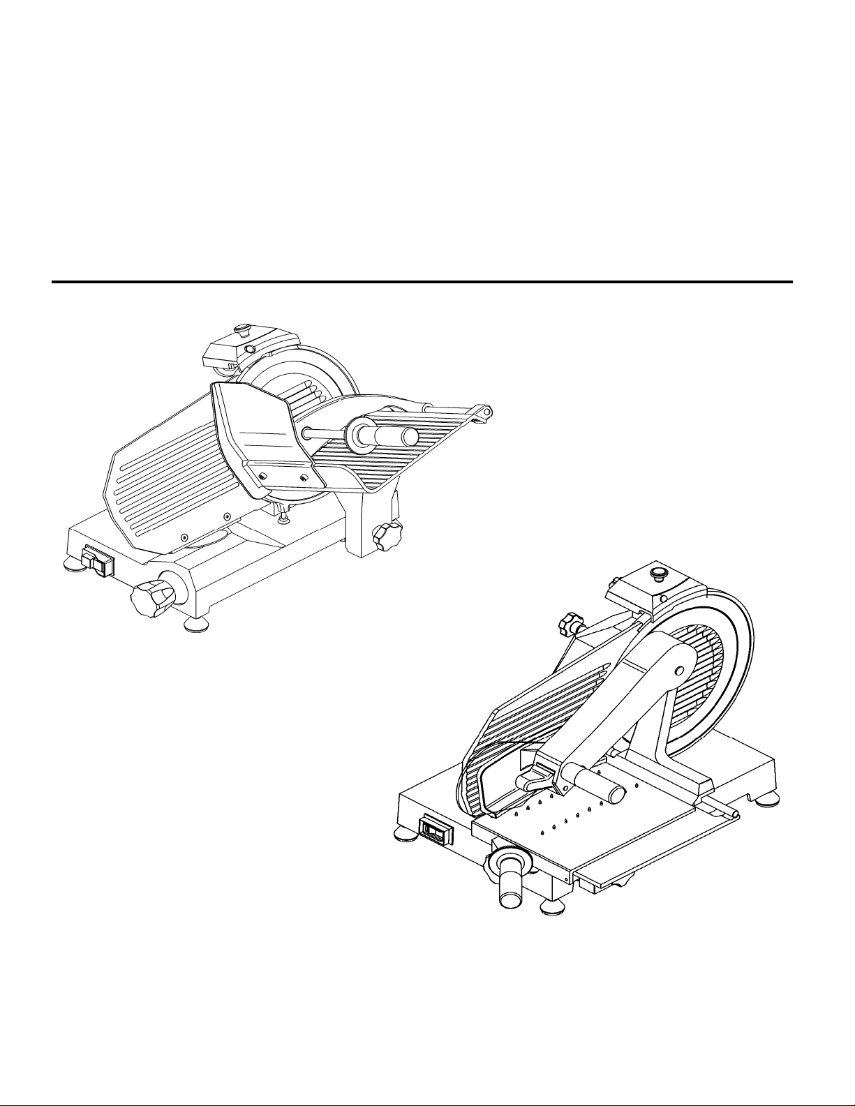
Professional slicer:
OPERATING AND MAINTENANCE MANUAL
M 220C - 220A.I.C - 250C - 275C - 300 C - 300 M
0C - 275C
25
M Vert.
M Vert. VCO 300
BS 250C - 275/C - 300
Vert. 220C -
Ed. 06/2021 - ver.
008
1
Page 2

INTRODUCTION
This manual is meant to provide customers with information on the slicer and its specifications
and the necessary operating and maintenance instructions in order to guarantee the best possible
of the machine and preserve its efficiency in the long term.
use
This manual is to be used by qualified and skilled people well informed about the use of the slicer and its
periodical maintenance.
BLE OF CONTENTS
TA
CHAP.
CHAP.
CHAP. 3 - SUPPLY OF THE SLICER pag. 12
CHAP. 4 - INSTALLATION p
1 - INFORMATION ON THE SLICER
1.1 - GENERAL PRECAUTIONS
1.2 1
.2.1
1.2.2
.3
1
1.3.1
1.3.2
1.3.3
2 - TECHNICAL DATA
2
.1 -
3.1 - DISPATCH OF THE SLICER
3.2
3.3
.1 -
4
4.2
4
.2.1
.2.2
4
.3
4
4
.3.1
4
.3.2
.3.3
4
.4
4
SAFETY SYSTEMS INSTALLED IN THE SLI
-
mechanical safety system
electrical safety system
SPECIFICATIONS OF THE SLICER
-
- general descrip
-
construction features
- slicer components
OVERALL DIMENSIONS, WEI
- PACKAGE CHECK UPON ARRIVAL
- PACKAGING DISPOSAL
SETTING UP OF THE SLICER
-
ELECTRIC CONNECTION
-
slicer equipped with a single-phase motor
slicer equipped with a three-phase motor
ELECTRIC CIRCUIT DIAGRAM
-
- Diagram of the sin
-
Diagram of the three-phase electric circuit - S Push-button panel
- Diagram of the sin
FUNCTIONING CHECK
-
tion
gle-phase electric circuit - S Push-button panel
gle-phase electric circuit - Professional switch
CER
GHT, CHARACTERISTICS
ag. 4
p
p
ag. 8
ag. 13
CHAP. 5 - OPERATING OF THE SLICER p
5.1 - CONTROLS
.2 -
5
5.3 - SHARPENING OF BLADE
CHAP. 6 - ORDINARY CLEANING
6.1 - GENERAL FEATURES
6
.2 .2.1
6
.2.2
6
LOADING AND SLI
SLICER CLEANING PR
- meat hopper cleaning
blade, blade guard and ring cleaning
-
CING OF FOODSTUFFS
OCEDURE
2
ag. 17
pag. 20
Page 3

.2.3
6
.2.4
6
sharpener cleaning of the sharpener
deflector cleaning of the deflector
-
CHAP.
7.1 - GENERAL FEATURES
7.2 - belt
7.3 - feet
7.5 - blade
7.6 - grinding mole
7.7 - lubrication of sliding guides
7.8 - label of the push-button panel
CHAP. 8 - MACHINE DISPOSAL p
7 - MAINTENANCE AND USEFUL ADVICE
7.4 - power supply cord
.1 -
8
8
.2
PUTTING THE MACHINE OUT OF SERVICE
-
WEEE Waste of Electric and Electronic Equipment
ag. 22
p
ag. 23
3
Page 4

C
HAP. 1 - INFORMATION ON THE SLICER
1.1 - GENERAL PRECAUTIONS
The slicer must be operated only by highly
measures described in this manual.
In case of a personnel turn over, training is to be provided in advance.
Although the slicer is equipped with safety devices in the dangerous points, it is
recommended not to
Before starting cleanin
socket.
Assess the
maintenance.
Cleaning and maintenance require great concentration.
A regular control of the electric supply cords is absolutely necessary; a worn-out or damaged cord
can expose users to great electric shock hazard.
If the slicer shows malfunctions, it is recommended not to use it and to abstain from trying to repair it;
please call the “SERVICE CENTRE”.
The slicer is designed for cutting fresh, seasoned and cooked meats, cured meats and vegetables,
non-frozen and boneless, up to maximum 20°C. Any other use must be regarded as improper and thus
dangerous.
Do not use the slicer without the help of the meat pusher, when the meat is nearly finished.
Do not place
Th
⇒if the slicer has been tampered by non-authorized personnel;
⇒if some parts have been substituted by non original spare parts;
⇒if the instructions contained in this manual are not followed accurately;
⇒if the slicer is not cleaned and oiled with the right products.
e manufacturer is not liable in the following cases:
residual risks carefully when protection devices are removed to carry out cleaning and
yourself in a dangerous position, the blade may cause injuries.
touch the blade and the moving components.
g and maintenance, disconnect the slicer plug from the supply
qualified people who are fully aware of the safety
1.2 - SAFETY SYSTEMS INSTALLED IN THE SLICER
1.2.1 - MECHANICAL SAFETY SYSTEM
The mechanical safety system of the slicer described in this manual complies with EC directives
2006/42.
The safety system includes (see 1.3.3):
lade guard;
- b
- ring;
- cover;
- meat pusher;
- meat pusher knob with ring nut and spacer;
- hand cover on the meat hopper;
- carriage only removable when the thickness gauge is set in the “0” position, at the end of its travel and
towards the operating side.
1.2.2 - ELECTRICAL SAFETY SYSTEM
The safety system installed to protect users against
2014/35/UE, 2014/30/UE and mod. 2006/42.
electrical risks is in compliance with directives
4
Page 5

e slicer is equipped with:
Th
- a micro-switch which stops the slicer in case the tie rod for blade guard is removed (see FIG. n°1); the
micro-switch prevents from restarting the slicer if the guard has not been set in the switch-off position.
- a relay in the control box which requires the restarting of the slicer when a power cut occurs. Even
though CE professional slicers are provided with electrical and mechanical protections (when the slicer
is working and for maintenance and cleaning operations), there are still RESIDUAL RISKS that
cannot be eliminated completely; these
lade and other parts of the machine can cause cuts and injuries.
b
.3 - SPECIFICATIONS OF THE SLICER
1
1.3.1 - general description
Our firm has designed and manufactured the CE line of professional slicers to cut foodstuffs (as salami,
meat and vegetables) in order to guarantee:
- the highest degree of safety in functioning, cleanin
risks are mentionned in this manual under WARNING. The
g and maintenance;
- the highest hygienic standards due to an accurate choice of materials and a smooth design of the slicer
components which come into contact with products so as to obtain easy and total cleaning and easy
disassembly;
- the greatest accuracy in cutting foodstuffs thanks to a cam mechanism;
- solidity and stability of components;
- the highest degree of noiselessness due to belt drive;
- great handiness.
1
.3.2 - construction features
e professional slicers CE are made of an aluminium alloy (AlMg3) treated by anodic oxidation.
Th
This procedure guar
salts and oxidation processes.
The blade is made of chromium plated steel 100Cr6; it is grinded and hardened to guarantee an accurate
and sharp cut of products also after it has been resharpened.
Most of the other components present are made of:
-
ABS plastic suitable f r contact with foodstuffs
- AISI stee
- alu inium.
antees high hygienic standards of the parts interested by the cut and resistance to acids,
5
Page 6
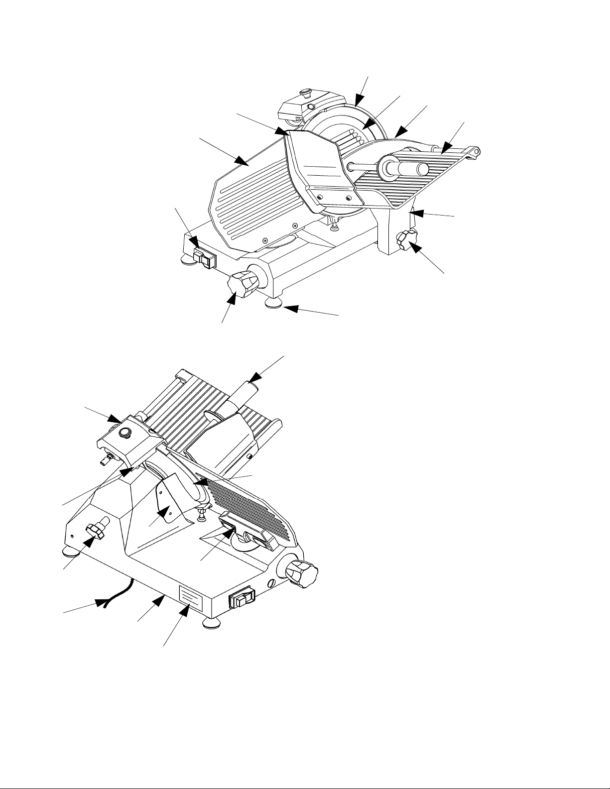
1.3.3 - Slicer components
M / M Vert.
21
1
2
3
4
6
5
20
LEGEND:
10
8
7
12
13
14
11
15
19
16
17
18
. Blade cover
1
2. Hand guard
3. Thickness gauge (plate)
4. Push-button panel
5. Dial knob
6. Feet
7. Carriage locking knob
8. Stem
9. Meat press
10. Meat hopper
11. Sharpener
12. Sharpener locking knob
13. Tie rod for blade guard
14. Power supply cord
15. Base
16. Rating plate - serial number
17. Thickness gauge support
18. Blade
19. Deflector
20. Meat press knob
21. Ring
FI
G. n°1a - General view of the slicer M / M Vert.
6
Page 7
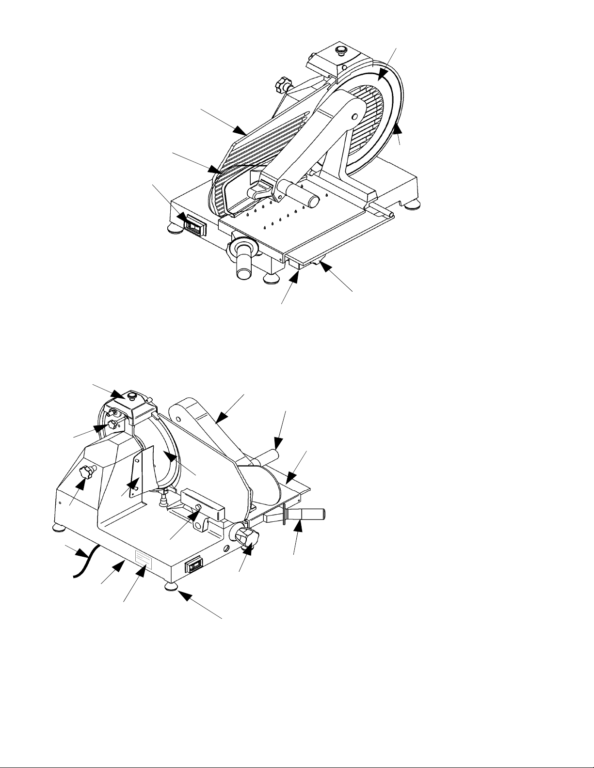
M Vert. BS
1
3
14
12
11
13
15
19
16
4
2
17
18
6
5
9
8
20
22
10
9
7
LEGEND:
1. Blade cover
2. Hand guard
3. Thickness gauge (plate)
4. Push-button panel
5. Dial knob
6. Feet
7. Carriage locking knob
8. Stem
9. Meat press
10. Meat hopper
11. Sharpener
12. Sharpener locking knob
1
3. Tie rod for blade guard
4. Power supply cord
1
15. Base
16. Rating plate - serial number
17. Thickness gauge support
1
8. Blade
9. Deflector
1
20. Meat press knob
21. Ring
22. BS Hopper push-handle
FI
G. n°1b - General view of the slicer M Vert. BS
7
Page 8
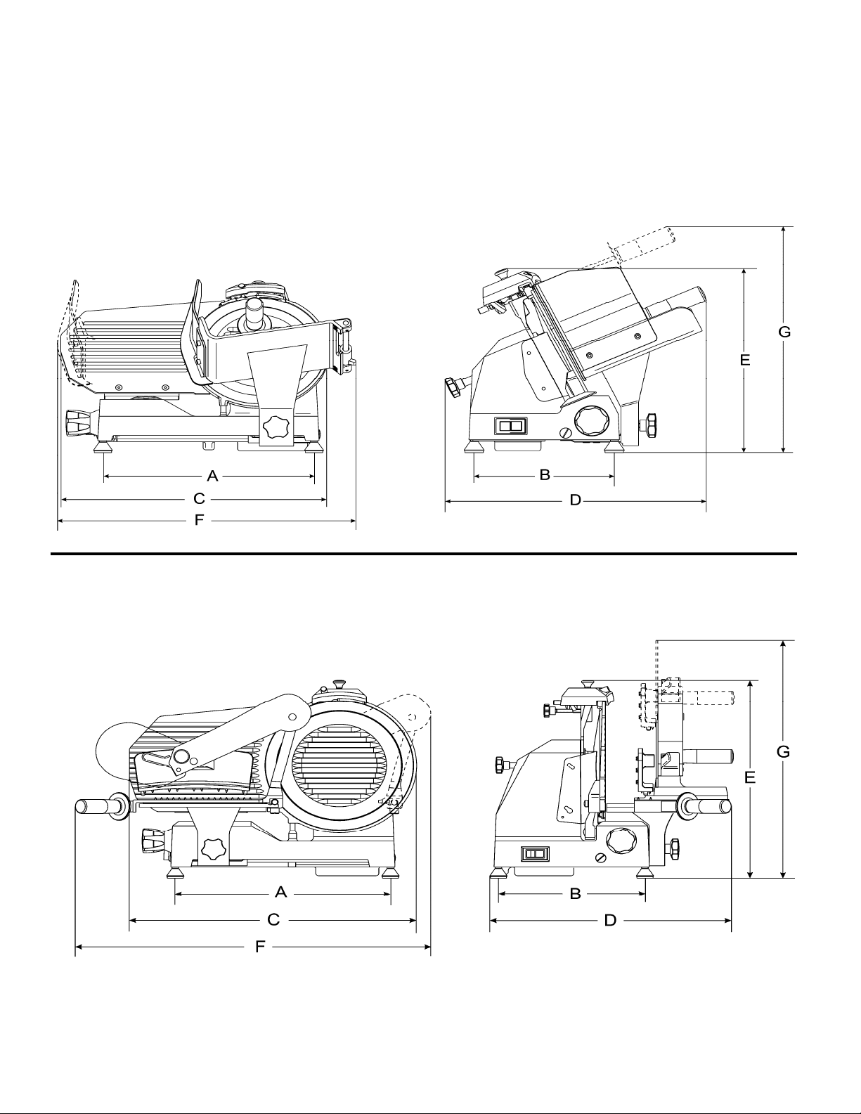
CHAP. 2 - TECHNIC
2
.1 - OVERALL DIMENSIONS, WEIGHT, CHARACTERISTICS ... FIG. n°2 -
Drawings of the overall dimensions
M / M Vert.
AL DATA
M Vert. BS
8
Page 9
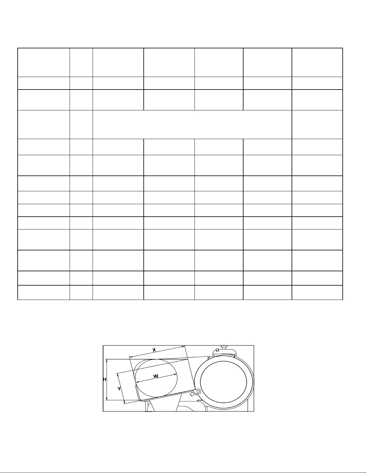
TAB. n°1 - OVER
MODEL
ALL DIMENSIONS AND TECHNICAL CHARACTERISTICS.
U
U.
.
M
20 C
2
2
20 AI C
M
50 C
2
M
75 C
2
M
00 C
3
3
M
00
Blade
ø
Mo
tor
Power Supply
Cut
thickness
Run
f carriage
o
Ho
pper size
A x B
C x D x E
x D x G
F
X
Y
mm
W
Hp
ph
1
3
ph
mm
mm
mm
mm
mm
mm
mm
20
2
47
1
0
,20
3
1
45
2
2
30x230
3
95x245
4
80x560x370
70x560x475
5
10
2
1
35
50
2
47
1
0
,20
30V / 50Hz
2
3
1
45
2
2
30x230
3
95x245
5
00x560x370 535x560x370 546x460x390 600x610x420
70x560x475 570x560x475 585x560x510 640x610x510
5
15
2
1
45
75
2
47
1
0
,20
3
1
45
2
2
30x230
3
95x245
15
2
1
65
00
3
47
1
0
,20
3
1
45
2
2
30x230
3
95x245
10
2
1
72
00
3
10
2
0
,29
30V / 50Hz
2
2
30-400V /
50Hz
3
1
85
2
2
50x275
4
35x295
50
2
1
85
H
W
Net weight
No
ise level
mm
Kg
d
B
170
60
1
1
5
6
0≤
180
70
1
1
6
6
0≤
200
90
1
1
7
6
0≤
205
92
1
2
0
6
0≤
225
10
2
2
0,5
6
0≤
9
Page 10
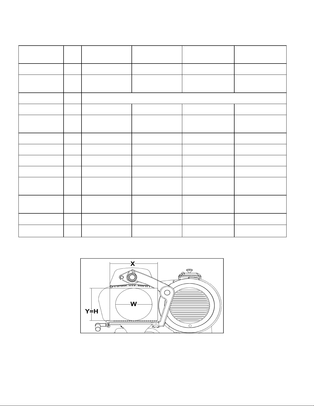
TAB. n°2 - OVER
MODEL
ALL DIMENSIONS AND TECHNICAL CHARACTERISTICS.
U
U.
.
M Vert.
2
20 C
M Vert.
2
50 C
M Vert.
2
75 C
M
Vert.
VCO 300
Blade
ø
Motor
Power Supply
thickness
Cut
Run
o
f carriage
Ho
pper size
A x B
C x D x E
F x D x G
X
Y
H
W
mm
W
Hp
ph
1
mm
mm
mm
mm
mm
mm
mm
mm
20
2
147
,20
0
3
1
25
2
230x235 230x235 230x235
00x260
4
5
00x535x400
70x535x405
5
205
50
1
50
1
1
50
5
5
50
2
147
,20
0
2
30V / 50Hz
3
1
30
2
00x260
4
10x535x410
70x535x410
205
70
1
70
1
1
70
00x260
4
5
30x535x420
70x535x425
5
75
2
147
,20
0
3
1
20
2
225
05
2
05
2
2
05
300
210
,29
0
13
265
255x235
440x300
585x540x460
740x540x770
255
215
215
215
Net
weight
No
ise level
Kg
d
B
16,5
0≤
6
17,5 18,5
60≤ 60≤
27
60≤
10
Page 11
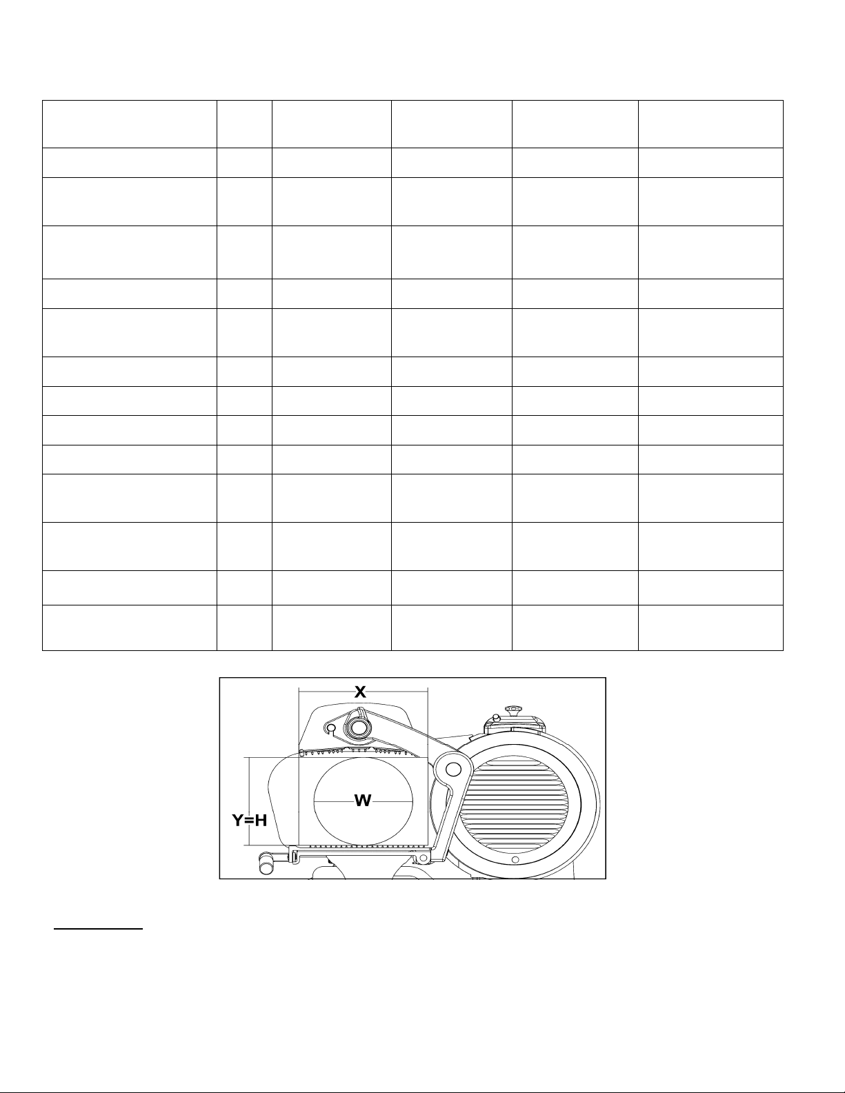
TAB. n°3 - OVERALL DIMENSI
U.
MODEL
U
.
ONS AND TECHNICAL CHARACTERISTICS.
M Vert.
50 C BS
2
M Vert.
75 C BS
2
M Vert.
75 BS
2
M Vert.
00 BS
3
Blade
ø
Motor
Power Supply
Cut
thickness
Run
f carriage
o
Ho
pper size
A x B
C x D x E
F
x D x G
X
Y
H
W
mm
W
Hp
ph
1
ph
3
mm
mm
mm
mm
mm
mm
mm
mm
2
50
47
1
,20
0
2
30V / 50Hz
3
1
2
15
75x270
2
4
00x260
5
10x480x415
700x480x600 700x480x770 740x500x630 740x540x770
70
2
90
1
190
90
1
2
75
47
1
,20
0
2
30V / 50Hz
3
1
2
25
60x275
2
4
00x260
5
30x480x420
70
2
00
2
200
00
2
2
75
10
2
,29
0
2
30V / 50Hz
3
1
2
20
85x260
2
4
40x300
5
80x500x455
55
2
05
2
205
05
2
3
00
10
2
,29
0
2
30V / 50Hz
230-400V / 50Hz
3
1
2
65
60x275
2
4
40x300
5
85x540x460
55
2
15
2
215
15
2
2
Net weight
Noise level
WARNING: Electrical features of the slicer are shown in the rating plate placed on the back side of the
machine; before connecting the
Kg
d
B
slicer to the electric system see § 4.2. Electric connections.
1,5
0≤
6
2
6
2,5
0≤
2
6
6
0≤
2
6
7
0≤
11
Page 12
CHA
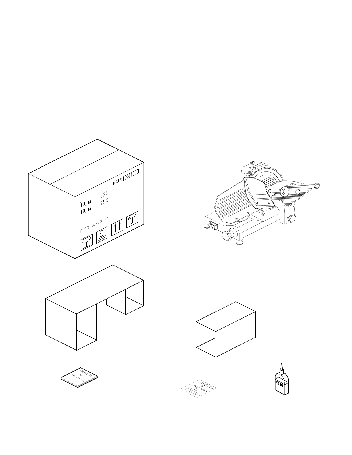
3.1 - DISPATCH OF THE SLICER (see FIG. n° 3)
Slicers are accurately packed and then dispatched from our warehouses; the package includes:
P. 3 - SUPPLY OF THE SLICER
a) ) a stron cardboard box;
b) the sli cer;
c) ) tw cardboard filling grafts to keep the slicer stable;
d) mthis anual;
e) ) oil phial;
f) EC conformity declar ation.
a)
)
b
FIG.
n°3 - Description of the package
c)
d
)
12
f)
e)
Page 13

3.2 - PACKAGE CHECK UPON ARRIVAL
I
f no external damage is evident on the package upon its arrival, open it and check that all the components
are inside (see FIG. n°3). If the package has suffered from rough handling, bumps or crashes, the carrier
must be informed about any damage; moreover a detailed report on the extent of the damage caused to the
machine must be filled within three days from the delivery date shown in the shipping documents. Do not
overturn the package!! When the package is transported, make sure, the box is lifted by the 4 corners
(parallel to the ground).
3.3 - PACKAGING DISPOSAL
The components of the packaging (cardboard box, pallets, plastic straps and polyurethane) are urban solid
waste; therefore they can be
If the slicer is to be installed in countries where specific regulations are in fo
easily disposed.
rce, packaging must be
disposed in compliance with them.
CHAP. 4 - INSTALLATION
4.1 - SETTING UP OF THE SLICER
The slicer must be installed upon a working table suitable for the slicer’s overall dimensions shown in
Ta
ble 1-2-3 (according to the model); therefore it must be adequately large, well levelled, dry, smooth,
esistent, stable and placed at a height of 80 cm from the ground. Moreover the machine must be installed
r
in a room with max. 75% not saline humidity at a temperature between +5°C and 35°C; that is to say in
a place that does not provoke the slicer failure.
4.2 - ELECTRIC CONNECTION
4.2.1 - slicer equipped with a single-phase motor
The slicer is equipped with a power supply cord (section of 3x1mm² and length of 1.5m) and a “SHUKO”
plug.
Connect the slicer with a 230 Volt - 50 Herz electric circuit by interposing a differentialmagnetothermic switch of 10A, ∆I = 0,03A. Check that the earthing is fully operational. Moreover check
that features on the rating plate - serial number (FIG. n°4) correspond to the features shown in the
consignment and delivery note.
4.2.2 - slicer equipped with a three- phase motor
The slicer is equipped with a power supply cord with a section of 5x1mm²and a length of 1.5m.
Connect the slicer with a 400 Volt - 50 Herz three-phase electric circuit by means of a CEI plug
interposing a differential-magnetothermic switch of 10A., ∆I = 0,03A.. Check that the earthing is fully
operational. Before connecting the machine to the three-phase power supply circuit, check the direction of
blade rotation by pushing the button “I” (ON) (see CHAP. 5.1 FIG. n°8) and immediately afterwards the
cut-off button “0” (OFF).
The direction of blade rotation must be anti-clockwise looking at the machine from the blade
g
uard side (see FIG. n°5).
FI
G. n°4 - Rating plate - serial number
(A)
(A) = Codice e nome articolo
(B) B)
Alimentazione
(C) = Frequenza motore
(D) = Amperaggio
(E) = Serial number
(F) = Codice a barre
(G) = Produttore
(H) = Grado di isolamento
(I) = Peso
(G)
(B)
(C)
(D)
(E)
LEGENDA
(H)
(I)
(L)
(F)
(M)
(L) = Potenza
(M) = Provenienza
13
Page 14
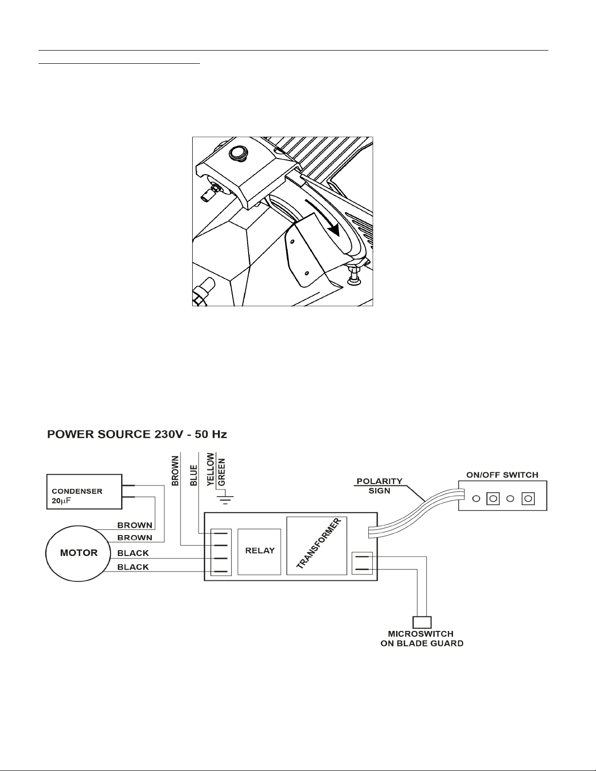
If the direction of rotation is wrong, rev
in the socket
Three-phase motors installed in CE professional slicers can work with both 230 V. three-phase tension and
400 V. tension.
Unless otherwise specified, connections are made with 400 V. power supply; call the “SERVICE
CENTRE” if matching with the 230 V three-phase circuit. is required.
(black and grey).
erse two of the three power supply cords in the plug or
FIG. n°5 - Sense of
4
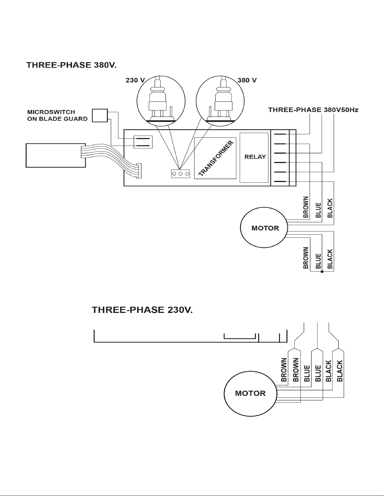
.3 - ELECTRIC CIRCUIT ARRANGEMENT
4.3.1 - arrangement of the single-phase electric circuit - Push-button panel
blade rotation
n°6 - Single-phase electric system arrangement
FIG.
14
Page 15
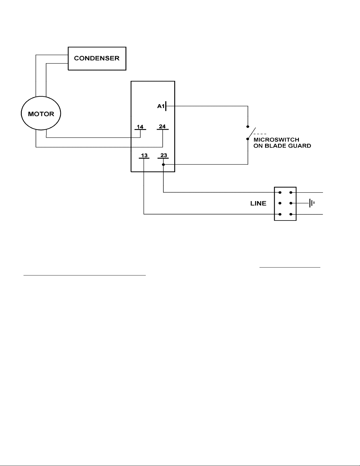
4.3.2 - arrangement of the three-phase electric circuit - Push-button panel
FIG. n°7 - Three-phase electric system arra
ngement
15
Page 16
4.3.3 - arrangement of the single-phase electric circuit - Schalter Profi
FIG. n°8 - Single-phase electric system arra
4
.4 - FUNCTIONING CHECK
Before testing the slicer check that the meat hopper is blocked and then try the functioning according to
the following procedure:
1 push the switch-on button “I” (ON) and the switch-off button “0” (OFF);
2 check the sliding of the meat hopper and meat pusher;
3 check the functioning and adjustment of the plate through the dial knob;
4 check the functioning of the sharper (see § 5.3, FIG. n°11 a-b-c);
5 check that the meat hopper can be disassembled only with the dial knob set in the “0”
position and that, after disassembling the machine, the knob remains in this position; 6 check that the
slicer stops functioning by unscrewing the tie rod for blade guard.
ngement - Schalter Profi
16
Page 17
HAP. 5 - OPERATING OF THE SLICER
C
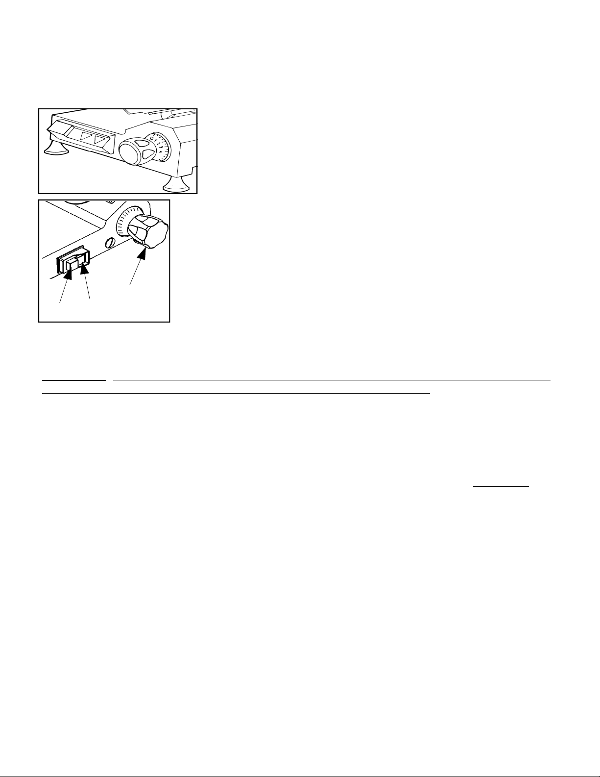
5.1 - CONTROLS
Controls are placed on the left hand side of the base as shown in the picture above.
Dial knob to adjust the
1
cuttingthickness.
2 Switch-on button “I”. 3
Switch-off button “0”.
1
3
2
FIG. n°9 - Position of controls
.2 - LOADING AND SLICING OF FOODSTUFFS
5
WARNING: Products to be cut must be loaded on the meat hopper only when the dial knob is set to the “0”
position and pay attention to the blade and the sharp edges.
The procedure is as follows:
1 once the product has been loaded onto the meat hopper and placed against the plate, stop it
with the arm provided with gripping points;
2 adjust the dial knob so as to obtain the desired cutting thickness;
3 to avoid accidents, the person who is cutting has to face the machine and stand correctly:
ut the right hand on the meat pusher, and then the left one beside the deflector (do not touch the
p
blade); the body must be perpendicular to the working surface (see FIG. n°10a). WARNING: Pay
the maximum attention: no members of your body should enter in contact with the blade (see
FIG. n°10b);
push the switch-on button “I”;
4
5 smoothly push the carriage (meat hopper + meat pusher + stem) towards the blade without
erting pressure on foodstuffs with the meat pusher since they have their own force of gravity
ex
which exerts pressure on the thickness gauge. The blade will easily cut foodstuffs and slices will be
guided by the deflector onto the collecting plate (see FIG. n°11);
6
do not operate the slicer without foodstuffs;
7 once foodstuffs have been cut, set the dial knob in the “0” position and switch off the
machine by setting the switch to the “0” position;
8 after slicing, do not leave the food lying on the product. Store the food that has just been
sliced in a place suitable for its preservation.
9 resharpen the blade as soon as slices show a rough or frayed surface and the cutting
b
ecomes difficult (see 5.3).
17
Page 18
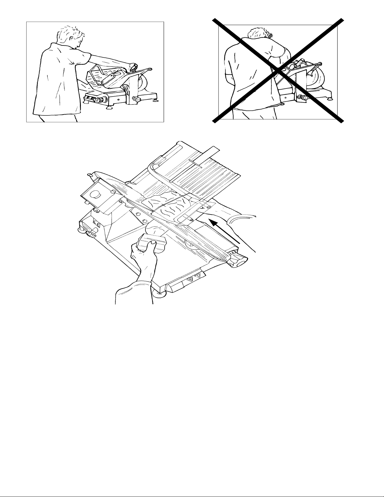
FIG. n°10a - Right position
FIG. n°10b - Bad position
FIG. n°11 - Meat cut
18
Page 19
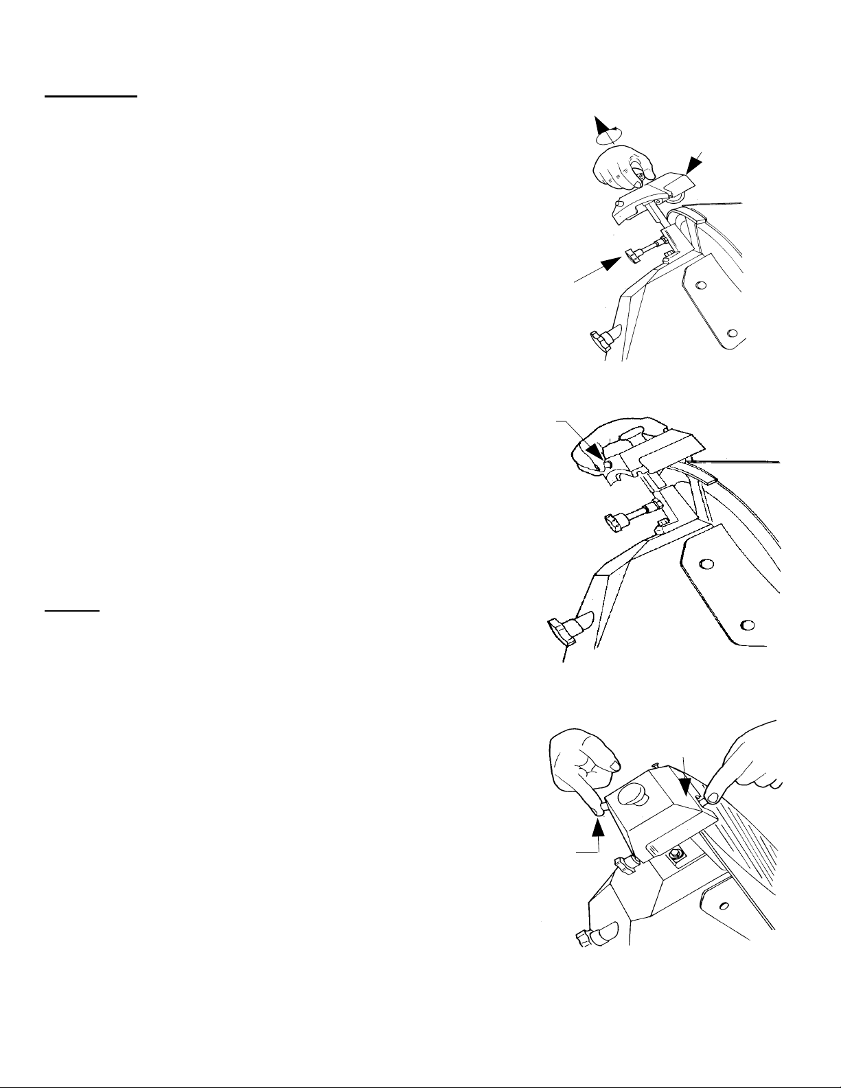
5.3 - SHARPENING OF BLADE (see FIG. n°12 a-b-c)
WARNING: Before proceding with blade sha
alert to the RESIDUAL RISKS (see §1.2.2) that refer to the hazard
of injury if the instructions below are not followed.
The blade must be sharpened periodically and as soon as it becomes
blunt; the following detailed instructions are to be carried out:
1 clean the blade accurately with denatu
remove grease after the plug has been disconnected from the socket;
unscrew the knob (1), lift (a) the sharpener (2) up to the
2
locking position and rotate it 180° (b) (see FIG. n°12a). Then let
it move to the end (c) so that the blade is positioned between
the two grinding moles. Lock the knob;
3
switch-on the slicer by pushing the button “I” (ON);
4 push the small button (3) (see FIG. n°12b), let the blade
rotate against the grinding mole for 30/40 sec. to produce burr on the
blade edge;
5 push buttons simultaneously for 1-2 seconds (3 and 4)
and then leave them simultaneously (see FIG. n°12c);
6 it is recommended to clean the grinding moles by
following the sharpening (see 6.2.3);
7 once sharpening has been completed, return the slicer to
its original setting with the reverse p
rated alcohol to
rocedure.
rpening, remain
1
G. n°12a
FI
3
a
b
2
E: Do not prolong the burring operation beyond 1-2 sec. in
NOT
order to prevent the dangerous twisting of the blade cutting edge.
FIG. n°12b
3
FI
G. n°12c
4
19
Page 20
CHAP. 6 - ORDINARY CLEANING
6
.1 - GENERAL FEATURES
The slicer cleaning must be carried out at least
Cleaning must be extremely accurate for those parts of the slicer which are directly or indirectly in
contact with foodstuffs.
The slicer must not be cleaned with water-cleaners and high pressure jets of water, but use water and
neutral detergent. Do not use other detergents. Tools, brushes and other devices likely to damage
the slicer’s surface must not be used.
B
efore carrying our any cleaning operation it is necessary to:
1) disconnect the power supply
completely;
2) set the dial knob adjusting the plate to the “0” position.
WARNING: Pay attention to residual risks due to cutting and/or sharp edges.
.2 - SLICER CLEANING PROCEDURE
6
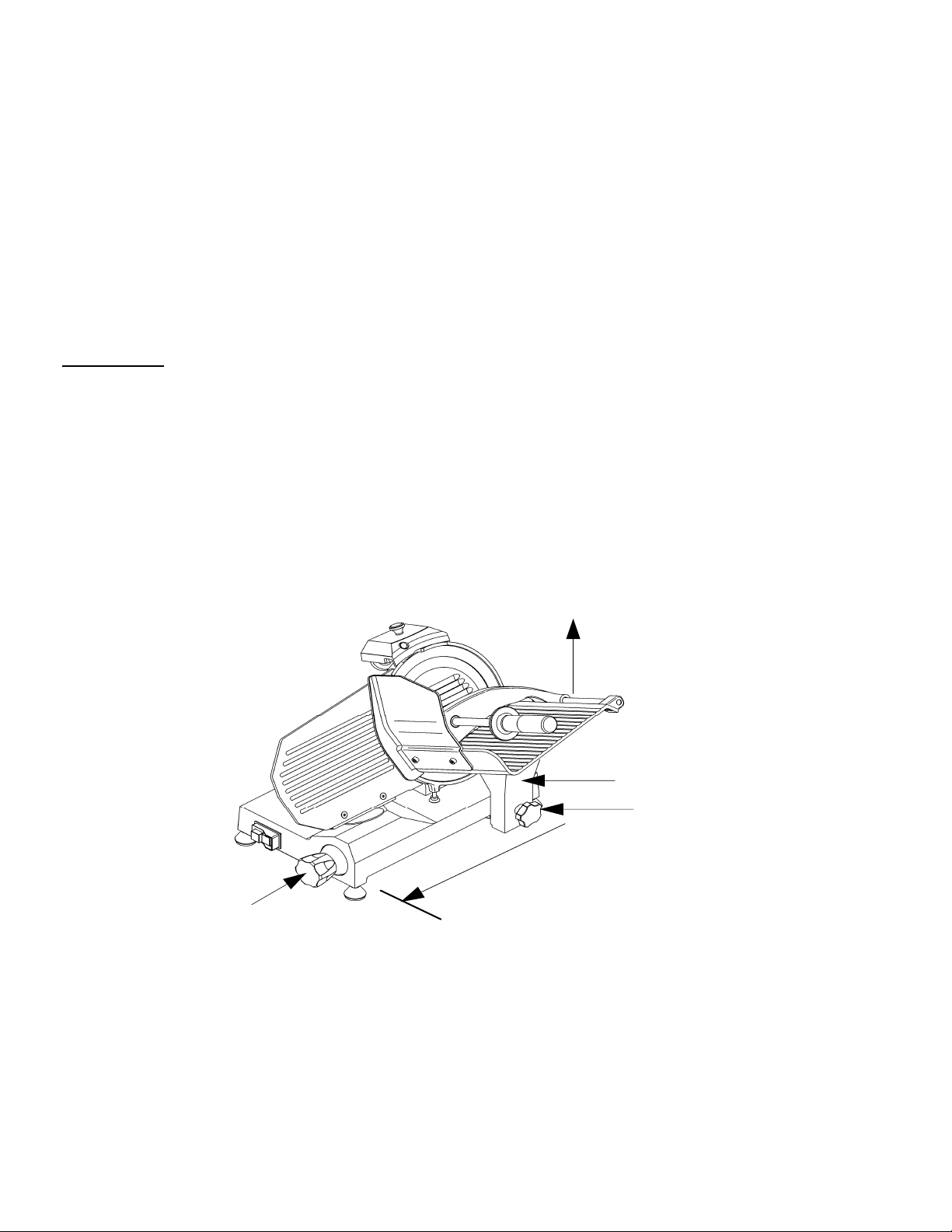
6.2.1 - meat hopper cleaning (see FIG. n°13)
The carriage (meat hopper + arm + stem) is easily removable:
plug from the socket to isolate the slicer from the rest of the electric circuit
- with the dial knob set in the “0” position (1);
- bring the carriage (2) to the end of its run (a) from the controls side; unscrew and remove the plate lock
handgrip (3), pull the trolley towards the operator with strenght; therefore lift the trolley up (b)
- after having removed the carriage, it is possible to clean accurately the meat hopper with hot water and
neutral detergent (PH 7).
once a day or more frequently, if necessary.
FIG. n°1
b
2
3
a
1
3 - Release of the carriage
20
Page 21
.2.2 - blade, blade guard and ring cleaning
6
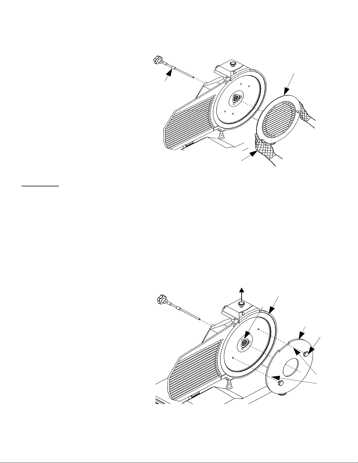
Unscrew the knob of the tie screw (1) (see FIG. n°14) to release the blade cover (2).
1
2
FIG. n°14 - Release of
WARNING: the blad
blade on the opposite surface, it is necessary to remove the blade (see FIG. n°15). The blade is to be
removed as follows:
1) disassemble the blade cover (see
2) remove (a) the sharpener and open the thickness plate with the dial knob to make the blade removal
tool (b) adhere to the blade;
3) loosen the 3 or 4 screws (f) (according to the model) that fix the blade;
4) lean the plexiglas blade removal tool on the blade to obtain the coupling of the blade holes with the
two screws (e), turn the blade until it reaches the correct position;
5) tighten the screws (e) not excessively.
N.B. the blade guar
hot water and neutral detergent.
blade guard
e cleaning must be carried out with metal gloves (3) and a wet cloth. To clean the
FIG. n°14);
d must be cleaned with
3
a c
f
b
FI
G. n°15 - Placing the mask in order to remove the blade
21
e
d
Page 22
6
.2.3 - cleaning of the sharpener
The sharpener cleaning operation is carried out by rubbing the grinding moles with a brush; the moles must be
placed in the safety position which means that they must be turned towards the side opposite to the blade.
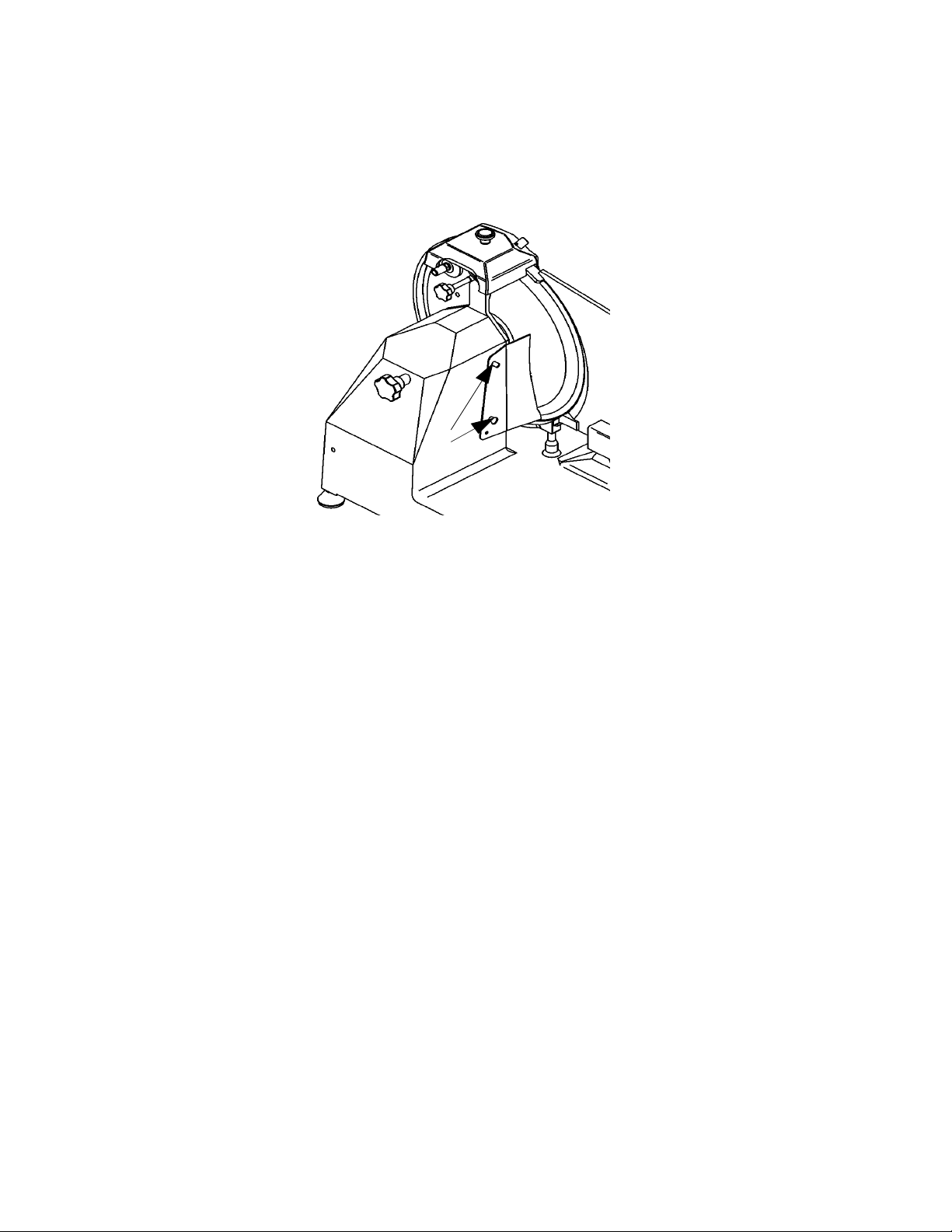
6.2.4 - cleaning of the deflector
The two screws (a) locking the deflector must be unscrewed to remove it (see FIG. n°16).
a
FIG. n.°16 - view of the deflecto
this stage clean the deflector with hot water and neutral detergent.
At
r
CHAP. 7 - MAINTENANCE
7.1 - GENERAL FEATURES
Before starting maintenance it is necessary to:
a) disconnect the power supply cord plug from the socket to isolate the slicer from the electric circuit
completely.
b) place the dial knob adjusting the thickness plate in the “0” position.
.2 - BELT
7
The belt is not to be adjusted. Generally it must be replaced after 3/4 years; in this case please call your
authorized “SERVICE CENTRE”.
7.3 - FEET
Feet may deteriorate and lose elasticity thus reducing the stability of the slicer. In this case they must be
replaced.
7.4 - POWER SUPPLY CORD
Periodically check whether the power supply cord is worn-out and, if this is the case, please call the
“SERVICE CENTRE” to have it replaced.
7.5 - BLADE
Check that the blade does not lose more than 10mm of its original diameter. To have it replaced call the
“SERVICE CENTRE”.
22
Page 23

7.6 - GRINDING MOLES
Check that the grin
replaced not to damage the blade; therefore call the “SERVICE CENTRE”.
7.7 - LUBRICATION OF SLIDING GUIDES
From time to time pour some oil drops (from the oil phial provided with the slicer) onto the round bar
along which the carriage slides back and forth; this operation can be carried out through the hole (OIL)
next to the dial knob.
7.8 - LABEL OF THE PUSH-BUTTON PANEL
If the label of the push-button panel has been damaged, call the “SERVICE CENTRE” to substitute it.
ding moles retain their abrasive property during sharpening operations. If they must be
CHAP. 8 - MACHINE DISPOSAL
8.1 - PUTTING THE MACHINE OUT OF SERVICE
If for some reason, you decide to put the machine out of service, make sure nobody can use it: disconnect it
from mains and eliminate the electrical connections
8
.2 - WEEE Waste of Electric and Electronic Equipment
Directive 2002/95/EC, 2002/96/EC and 2003/108/EC on the restriction of the use o
substances in electrical and electronic equipment, and waste electrical and electronic equipment
This symbol, crossed out wheelie bin, on the product or on its packaging indicates that this product must
not be disposed of with your other household waste.
Separate waste collection of this appliance is organised and managed by the manufacturer. It is the user’s
responsibility to contact the manufacturer and follow the waste treatment system the manufacturer has
a
dopted for separate waste collection.
The separate collection and recycling of your waste equipment at the time of disposal will help to conserve
atural resources and ensure that it is recycled in a manner that protects human health and the
n
environment.
f certain hazardous
23
Page 24

SERVICE CENTRE
AUTHORISED
DEALER
24
 Loading...