

Page 1

Professional Hand-Held Mixer
S 20
Regular,
Speed variator,
SERVICE CENTRE
AUTHORISED DEALER
24
Ed. 11/2015
Instructions for use and maintenance
1
Page 2

CHAP. 8 - DISPOSAL OF THE MACHINE
8.1 - DISINSTALLATION
If it has been decided to disinstall the machine for some reason, ensure that the
machine is unusable by anyone: detach and cut electrical connections.
8.2 - WEEE Waste of Electric and Electronic Equipment
Directive 2002/95/EC, 2002/96/EC and 2003/108/EC on the restriction of the
use of certain hazardous substances in electrical and electronic
equipment, and waste electrical and electronic equipment.
This symbol, crossed out wheelie bin, on the product or on its packaging indicates that
this product must not be disposed of with your other ho use hold waste.
Separate waste collection of this appliance is organised and managed by the
manufacturer. It is the user’s responsibility to contact the manufacturer and follow the
waste treatment system the manufacturer has adopted for separate waste collection.
The separate collection and recycling of your waste equipment at the time of disposal
will help to conserve natural resources and ensure that it is recycled in a manner that
protects human health and the environment.
2 23
Page 3

CHAP. 7 - MAINTENANCE
7.1 - GENERAL INFORMATION
Before carrying out any maintenance task, it is recommended to:
unplug the feeding cable from the net to insulate the machine from the rest of the
plant completely.
7.2 - DIPPING OF ACCIDENTAL FALL OF THE MACHINE
In case of immersion or accidental fall of any accessory or the machine itself, do
not use it and contact CUSTOMER SERVICE.
7.3 - SHAFT
Check that the shaft is firmly and solidly fixed to the engine’s body. If this is not
the case, please contact CUSTOMER SERVICE.
7.4 - FEEDING CABLE
Periodically, check the state of wear of the feeding cable and in case, contact
CUSTOMER SERVICE.
7.5 - COMMANDS LINING
Periodically, check the state of wear of the rubber commands lining and in case
of wear contact CUSTOMER SERVICE.
7.6 - BLADE
Check the sharpness of the shaft’s blades to replace them, please contact
CUSTOMER SERVICE.
7.7 - GASKETS - SEALING RINGS
Periodically check the sealing gaskets, once the knife-holding base is
disassembled (Fig. n°51).
If these show wear, contact CUSTOMER SERVICE.
INTRODUCTION
This manual has been written to supply the Customer with all the information on the
machine and the related safety rules, as well as the instructions for the receipt of the
machine itself, cleaning, maintenance and disposal that allow to use and maintain the
means keeping its efficiency intact throughout the time.
This manual it to be kept till the disposal of the machine.
This manual is to be kept at disposal of members of staff that have been appointed to
operate the machine and to carry out maintenance tasks.
TABLE OF CONTENTS
CHAP. 1 - RECEIPT OF THE MACHINE page 5
1.1 - PACKAGING
1.2 - BOX CHECK UPON RECEIPT
CHAP. 2 - INSTALLATION page 6
2.1 - UNWRAPPING
2.2 - PLACEMENT
2.3 - ELECTRICAL CONNECTION
2.4 - ELECTRICAL DIAGRAM
CHAP. 3 - MACHINE’S INFORMATION page 8
3.1 - GENERAL PRECAUTIONS
CHAP. 4 - GETTING ACQUAINTED WITH THE MACHINE page 11
4.1 - IN-BUILT FEATURES
4.2 - IN-BUILT SAFETY DEVICES
4.2.1 - Mechanical safety devices
4.2.2 - Electrical safety devices
4.3 - MACHINE’S DESCRIPTION
4.4 - OVERALL DIMENSIONS, WEIGHT, FEATURES
CHAP. 5 - USE OF THE MACHINE page 15
5.1 - ACCESSORIES ASSEMBLY
5.2 - PREPARATORY CHECK
5.3 - USE’S FIELDS
5.4 - MACHINE’S USE
CHAP. 6 - REGULAR CLEANING page 19
6.1 - GENERAL INFORMATION
6.2 - EXTRA CLEANING
6.2.1 - GENERAL INFORMATION
22
3
Page 4
CHAP. 7 - MAINTENANCE page 22
7.1 - GENERAL INFORMATION
7.2 - DIPPING OF ACCIDENTAL FALL OF THE MACHINE
7.3 - SHAFT
7.4 - FEEDING CABLE
7.5 - COMMANDS LINING
7.6 - BLADE
7.7 - GASKETS – SEALING RINGS
CHAP. 8 - DISPOSING OF THE MACHINE page 23
8.1 - DISINSTALLATION
8.2 - WEEE Waste of Electric and Electronic Equipment
(Fig. n°50)
Such operation is an exclusive re-
quirement of this machine.
This operation is to be carried out
only in case of poor cleaning tasks
executed by previous operators or in
case unpleasant smells, internal encrustations, etc. can be perceived.
This operation is quite delicate and
particular even if simple and could
compromise the functioning of the
machine. Therefore, it is recommended to have it carried out only by
responsible and expert members of
Fig. n°50
staff.
ATTENTION: this operation exposes
the operator to risks due to the manipulation of knives and sharp parts. Hence, it
is recommended to use protective gloves and to be extremely careful all the
time.
Disassembly of the shaft (Fig. n°51)
1. Detach the shaft from the engine’s body and position it on a surface with the
knives on the right side.
2. Predispose the tools (a-b), grip the tool (b) with the left hand and insert it in the
dragging device inside the shaft
3. ATTENTION: Using a key (a), unscrew clockwise till the blade group is re-
moved.
4. Remove the inner shaft from the main shaft pushing it towards the tool (b).
5. Proceed to clean the single pieces with a dump cloth and some dish detergent,
keeping in mind that the bearings must not come into contact with liquids.
6. In case of encrustation, insist with the cloth. Do not use abrasives, pointy or
sharp tools.
7. Disassemble everything the opposite way. ATTENTION: fix firmly the knife or
this could detach itself during the operating stage.
2
(b)
3
1
(a)
4
21
Fig. n°51
Page 5

5) Empty the container, rinse it and fill
it with warm water. Let the machine
operate again for some more 10-15
seconds, if necessary repeat the operation till a complete and thorough
rinse is guarantied.
6) Check the result of the operation
and if necessary repeat from point
(2) or intervene manually on the
parts that are still dirty.
ATTENTION: At this stage it may be
instinctive to approach the blades
with your hands.
could provoke wounds to the hands
(Fig. n°46). Always disconnect the
machine from the power supply and
always pay maximum attention.
7) Reuse the tool for another operation
or:
8) Dry the tool with a cloth and position
it vertically for 1 or 2 hours to ease
the drainage of residual liquid (Fig.
n°47).
ENGINE’S BODY:
1. unplug the feeding cable from the
net to insulate the machine from the
electrical feeding completely (Fig.
n°48).
2. Remove possible product splashes
that deposited on the machine’s
body with a wet sponge and dry immediately with a cloth.
3. Check that no residual from the
work nor liquid did not enter the
cone fixing the tools and in such
case remove them with a cloth.
6.2 - EXTRA CLEANING
6.2.1 - GENERAL INFORMATION
The knives area
ATTENTION!
Fig. n°46
Fig. n°47
Fig. n°48
CHAP. 1 - RECEIPT OF THE MACHINE
1.1 - PACKAGING
The package includes:
engine’s body
operating shafts
manual
(Fig. 1): cartoon box, polystyrene
inserts, nylon, etc. will have to be
disposed of separately as per the
enforcing norms of the country of
installation.
ATTENTION!
Superimpose up to a maximum of
five boxes of the same type (Fig. 2).
It is recommended to keep the box at
least throughout the time of warranty to
facilitate transportation in case of repairs, etc.
Do not leave the box exposed to humidity and rain (Fig. 3).
Fig. n°1
Fig. n°2
Fig. n°3
20
Fig. n°49
Do not overturn the box (Fig. 4).
Fig. n°4
5
Page 6

Please ensure that the box is held
firmly at the far ends of its longest
sides, while carrying it and keep the
box itself parallel to the floor (Fig. 5).
1.2 - BOX CHECK UPON RECEIPT
Once the item has been received, proceed to the opening and check that all the
material is inside if the box does not show
external damages. While if the box or the
contents show signs of misusing (Fig. 6),
knocks, fall or ruptures, it is necessary to
inform the freight forwarder of the damage by writing a detailed report about the
possible damages suffered within three
days of the delivery date. Generally, complaints that are not communicated immediately are not taken into consideration by
the freight forwarder.
CHAP. 2 - INSTALLATION
ATTENTION!
All the tasks must be carried out by
trained members of staff (Fig. 7).
2.1 - UNWRAPPING
Ensure that the box is not upturned by
checking the direction of the external
writings (Fig. 8)
The contents include:
a) cartoon wrapping
b) inserts
c) the machine’s body
d) operating shaft
e) the instructions manual
Remove the adhesive tape fixing the
upper flaps of the box and lift the
machine’s body.
CHAP. 6 - REGULAR CLEANING
6.1 - GENERAL INFORMATION
The cleaning of the machine is an
operation to be done absolutely at
the end of every working cycle.
Immediate cleaning, can save a lot of
time, guaranties hygiene and mainte-
Fig. n°5
nance of the machine.
The cleaning must be scrupulously
detailed in all the parts that come
into direct or indirect contact with
food.
The dipping blender must not be
cleaned with water cleaners or water
jets (Fig. n°43), and/or with acid or
corrosive detergents that can ruin the
surface (Fig. n°44).
Tools and brushes or else must not
be used as they might damage the
Fig. n°6
machine (Fig. n°44).
Check that the vent’s opening are
not obstructed by dust, dirt or else
periodically. In case these are obstructed call the CUSTOMER CENTRE.
ATTENTION: do not use air jets or
else that could provoke dirt’s infiltra-
tions inside the machine (Fig. n°43).
For a correct cleaning, it is necessary:
SHAFT (Fig. n°45)
1) Get a container sufficiently high to
Fig. n°7
immerge the shaft to the maximum
level allowed
2) Fill it with hot water 50-60º C and
a-b)
c)
add dish detergent according to the
need
3) Let the machine operate for 20 seconds simulating the normal productive process.
d)
4)
When the motor is off, using a non-
abrasive damp sponge, clean the
e)
Fig. n°8
6
outside of the shaft with the deter-
gent previously used (Fig. no. 47).
Fig. n°42
Fig. n°43
Fig. n°44
Let the dipping
blender work for 20
seconds during the
cleaning stage.
19
Fig. n°45
Page 7

Alternate the revolution even in the
movements from the top to the bottom
to ease the entry of the products to be
cut in the operating bell (Fig. n°39).
Work till the desired consistency is
obtained, once finished using it,
switch the machine off.
ATTENTION: Do not use the machine in free air and to avoid any
risk of physical or mechanical
damage, never extract the tool
from the product while still rotating
(Fig. n°40).
ATTENTION: as a result of the centri-
fuge effect, the liquid tends to rotate
and to higher its level closer to the
border of the container, when the
blender is functioning, hence never fill
the container over 2/3 of its capacity
(Fig. n°39-40).
Never carry out work cycles for over
10 minutes and keep the blender
switched off anyway for at least 10
minutes between a work cycle and
the next (Fig. n°41).
At the end of the working cycle, remove the machine from the working
container and proceed immediately to
the cleaning of the tool (see chapter
6 Regular cleaning).
Never leave the machine unattended inside the container.
Cicli di lavorazione:
10 minuti ON - 10 min. OFF
Fig. n°39
Fig. n°40
Fig. n°41
2.2 - PLACEMENT
The machine and its related accessories must be kept in a dry environment, far away from heat, humidity,
splashes, dust and anything else that
might damage the dipping blender
and its accessories (Fig. 9).
In case the accessories are unused
for a long time, they might be stored
in other places as long as these latter
respect the above-mentioned requirements and that they guarantee good
conservation of the accessories themselves (for instance, drawers that can
bump the components one against
the other or cause them to fall must
be avoided).
2.3 - ELECTRICAL CONNECTION
Check that the data reported on the
register-technical plate (Fig. 10) of the
delivery documents match the
delivery documents, if not please
contact the supplier to have an
explanation.
At this point, make sure that
the
electric plant of the building is
according to law.
The dipping blender is supplied with a
feeding cable with section 2x1 mm
2
,
length > 1,6m and a SHUKO plug
(Fig. 11).
The machine is not foreseen to be
ground mass as it is supplied with
double isolation. This means that all
the external components that might
be handled by the operator cannot be
subjected to tension not even in case
of failure.
Link the dipping blender 230 V. – 50
Hz, interposing a differential (safety
device, Fig. 12) - 10A ∆Ι = 0.03Amagnetothermic switch.
Fig. n° 9
Fig. n°10
Fig. n°11
Fig. n°12
18
7
Page 8

2.4 - ELECTRICAL DIAGRAM 115V. – SINGLE-PHASE 230V. (Fig. 13)
Normal version
VV version
Fig. n°13
CHAP. 3 - MACHINE’S INFORMATION
3.1 - GENERAL PRECAUTIONS
Even if these general precautions seem obvious, they are of paramount importance for the installation, the use, the maintenance and possible inconveniences
and related remedies.
The producer has no responsibility
in the following cases:
The machine has been tampered
by non-authorised members of
staff.
Some components have been
replaced with non-original ones.
The instructions of this manual
have not been followed carefully.
Keep this manual with care for fu-
ATTENTION!
Fig. n°14
5.4 - MACHINE’S USE
ATTENTION:
- Check that the machine is perfectly
dry and that there is no dirt or humidity from previous uses or washes
(Fig. n°35).
- Check that the shaft or the whip
have not residual encrustations from
previous uses.
- Before using it, ensure that the shaft
and the whip are fixed to the en-
gine’s body properly (Fig. n°36).
- Check that in the previous uses the
components or protections have not
been removed.
- Check the state of the feeding cable
that could have been worn out by
the different knives and tools in the
kitchen. In this case, please contact
CUSTOMER SERVICE immediately.
Grip the dipping blender by the handle
with one hand and grip the lowest part
with the other one. Never grip the engine’s body in a way to obstruct the
vent’s opening (Fig. n°37).
Posture correctly and comfortably in order to work safely and easily. It is not
recommended to use the dipping
blender on kettles positioned above
fires or work surfaces that are too high
(Fig. n°38).
Immerse the immersion blender with
the utensil slightly tilted, making sure
that the blade unit does not touch the
bottom of the container. For optimal operation, the shaft must be submerged
up to ⅔ of its length.
Switch the machine (please see paragraph 5.1) and move the shaft towards
the inner part of the container with slow
but regular revolving movements.
Fig. n°35
Fig. n°36
Fig. n°37
⅔
Fig. n°38
8
17
Page 9

starts at maximum speed. Be aware of
the counterblow that the engine’s
power can provoke in the hand and in
the wrist when gripping the machine
tightly.
- If the machine has a speed variator,
after the engine has started, work on
the speed variator’s handle (4) with
the other hand and check the correct
its functioning
- Check if the machine starts even
without pressing the button (1). In
this case, give up the test and call
the producer immediately.
5.3 - USE’S FIELDS
The dipping blender has been designed
to blend, fruit, vegetables, meat, foodstuffs in general not frozen and in any
case soft.
The dipping blender has not been designed to work chemicals, sewages,
glues and anything that is not strictly
food.
Even if designed to blend also hot products, it is recommended to operate with
products at a temperature below 70 degrees C. always for a short lapse of
time (maximum 10 minutes).
Blending:
Use of the shaft (Fig. n°34).
Fruit, vegetables, meat, food in general
as long as mixed in some liquid solution.
Food pieces must have maximum dimensions of a nut (3x3x3 cm cubes as
long as without bones or stones and as
long as they are not too hard and consistent).
2-Speed variator’s handle
1-Switch on
Fig. n°33
Fig. n°34
ture reference (Fig. 14).
The dipping blender must be used
only by trained members of staff,
who must know the safety rules contained in this manual perfectly.
In case of staff turn-over, please
proceed to train the new members
of staff in timely fashion.
Do not allow children, incompetents
or untrained members of staff to use
the blender (Fig. 15).
Before carrying out any cleaning or
maintenance task, unplug the machine from the electrical feeding network (Fig. 16).
Before replacing accessories, un-
plug the machine from the electrical
feeding network (Fig. 16).
When intervening for ordinary main-
tenance or cleaning, carefully evaluate risks.
Focus your attention on the opera-
tions in course during the use, maintenance and cleaning.
To clean the machine, follow care-
fully the instructions of the chapter
“Ordinary cleaning”.
Do not wash the blender by means
of the dishwasher or water jets (Fig.
17-18).
The dipping blender has been de-
signed to blend fruit, vegetables and
meat (unfrozen and without bones
or stones) (Fig. 19), and anyhow
food that is not particularly hard or
resistant to be processed. Any other
use is to be considered improper
and therefore dangerous.
Dry the machine’s body and the
used accessories after having
cleaned them.
Do not expose the blender to nox-
ious agents such as the sun, the
rain, splashes, humidity, frost (Fig.
20).
Fig. n°15
Fig. n°16
Fig. n°17
Fig. n°18
Fig. n°19
Fig. n°20
16
9
Page 10

Do not pull the feeding cable to un-
plug (Fig. 21).
Check the status of the feeding ca-
ble on regular basis as a worn out
cable or imperfect presents serious
electrical dangers.
If the machine remains unutilised for
a long time, have it checked by an
Customer Service Centre before using it.
If the machine shows signs of mal-
functioning, it is recommended to
switch it off, not to use it and not to
intervene directly.
to repair it and call the Customer
Service Centre whose details can
be seen at the back of this manual.
In case of fall or immersion of the
blender, do not use it and contact
CUSTOMER SERVICE immediately
to have a detailed check.
Do not leave the dipping blender
plugged in pointlessly. Unplug it
when not using the machine. (Fig.
22).
Do not hang f handle the dipping
blender by means of the feeding cable (Fig. 23).
Even if the machine is built accord-
ing to the enforcing laws, there are
some dangerous zones. Therefore,
it is recommended to avoid to approach the hands to the blades or
other parts in movement (Fig. 24).
Do not posture in such a way that
might lead parts of the body in
direct contact with the blades.
10
Fig. n°21
Fig. n°22
Fig. n°23
Fig. n°24
CHAP. 5 - USE OF THE MACHINE
5.1 - ACCESSORIES ASSEMBLY:
The tools must be installed on the engine’s body when the machine is unplugged.
All the dipping blender’s tools are perfectly interchangeable. However, they
might differ according to the model,
date of production, producer. Hence, it
is recommended to keep separate the
various accessories of other dipping
blenders.
ENGINE’S BODY - SHAFT (Fig. n°31)
Grip the engine’s body by the handle,
grip the shaft with the other hand. Align
the shaft’s rung to the clutch of the machine’s body (1). Insert the shaft deeply
(2) and rotate it of about 45° degrees
anticlockwise till the shaft is firmly
blocked to the machine (3). The catch
will fit the engine’s body reference.
5.2 - PREPARATORY CHECK
Check that the tools are perfectly as-
sembled as per chapter 5.
Check that the electrical connections
has been done correctly as per para-
graph 2.3.
Hold the machine with a hand and after
that check its functioning with the fol-
lowing procedure (Fig. n°32-33):
- Ensure that the switch (1) is not
pushed
- Insert the machine’s plug into the
socket
- Hold the blade unit near the table, in
any case away from utensils, garments and parts of the body.
- Press the power button (1). The ma-
chine will start to work.
- If the machine is normal the engine
15
(1) (2)
(3)
Fig. n°31
Fig. n°32
Page 11

by this manual under the titles ATTENTION
. They concern the danger of cut,
contusion and else that is provoked by the blade and the dragging device, by
the whip and by other components of the machine or by electrocutions.
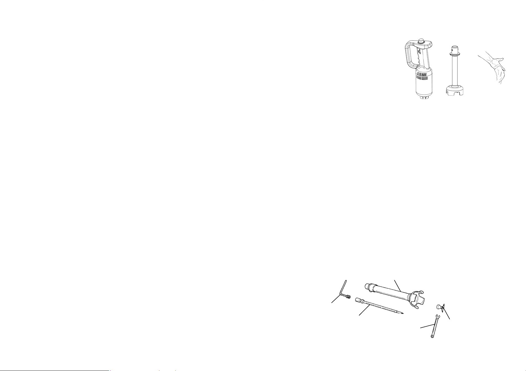
4.3 - MACHINE’S DESCRIPTION
Hand-Held Mixer (body only) Shaft
C
C
CHAP. 4 - GETTING ACQUAINTED WITH THE MACHINE
The dipping blender is made up by more elements than the ones that in this
manual are named:
- Engine’s body
- Operating shaft.
4.1 - IN-BUILT FEATURES
The engine’s body is built in highly-resistant ABS with stainless steel details.
These materials guarantee hygiene when there is contact with food and good resistance to the agents contained by food. Moreover, high mechanical resistance
is guaranteed due to their formation.
The operating shaft is made up almost completely by stainless steel, aluminium
and coated in highly-resistant ABS.
A
Fig. n°30
A B
4.4 - OVERALL DIMENSIONS, WEIGHT, FEATURES
ATTENTION:
The electrical features of the machine are indicated by a plate placed by the grip
(Fig. n°10).
TABLE 1 - OVERALL DIMENSIONS A ND TECHNICAL FEATURES (Fig. n°30)
Power Power source Knives
watt r.p.m. lt mm Kg
S 20 200 230V/50Hz 12.500 20 74X145X290 1,1
S 20 VV 200 230V/50Hz 2000÷12.500 20 74X145X290 1,1
A Net weight
mm mm kg
Shaft 16 ø 65 160 0,2
revolution
C
14
Working
Capacity
AxBxC Net
weight
KEY (see Fig.25):
01
variator with stabilizator
02
upper-grip handle
03
air-exhaust grill
04
dragging device (female)
05
air-aspiration grill
06
switch
07
dragging device (male)
08
hooking cone
09
hooking rung
10
tube
11
bell
12
blade
11
Page 12

Hand-Held Mixer Engine’s body
4.2 - IN-BUILT SAFETY DEVICES
01
06
02
05
04
Operating shaft
09
07
08
10
11
12
03
Fig. n°25
4.2.1 - Mechanical safety devices
As far as mechanical-nature safety, the
dipping blender described by this manual complies to:
- the EC 2006/42 machine’s directives
The dipping blender is provided with:
- Shaft-protecting bell (Fig. 27)
- Anti-accidental switching handle
(Fig. 29)
- Respect of the minimum space to
grip the machine as per what is prescribed by law
4.2.2 - Electrical safety devices
As far as electrical-nature safety, the
dipping blender described by this man-
ual complies to:
- the EC 2006/95 low tension directive
- the EC 2004/108 electro-magnetic
compatibility directive
Therefore the dipping blender is provided with:
- Double-insulating system to guaran-
tee that all the details that might
come in contact with the operator
are not subject to tension not even
in case of breakdown.
- Ergonomic positioning of the start
button to prevent accidentally pow-
ering (Fig. no.29).
- Internal components protection from
liquid splashes
- Although the dipping blender is pro-
vided with the electrical and mechanical measures (operating during
the working phase and during cleaning and maintenance) as per the en-
forcing laws, there are some RESID-
UAL RISKS that cannot be elimi-
nated completed. These are recalled
Aspiration
grill air
Escape grill
air
Fig. n°26
Fig. n°27
Fig. n°28
Fig. n°29
12
13
 Loading...